

Page 1
octagon v2.16 Page 1
OCTAGON
USER GUIDE
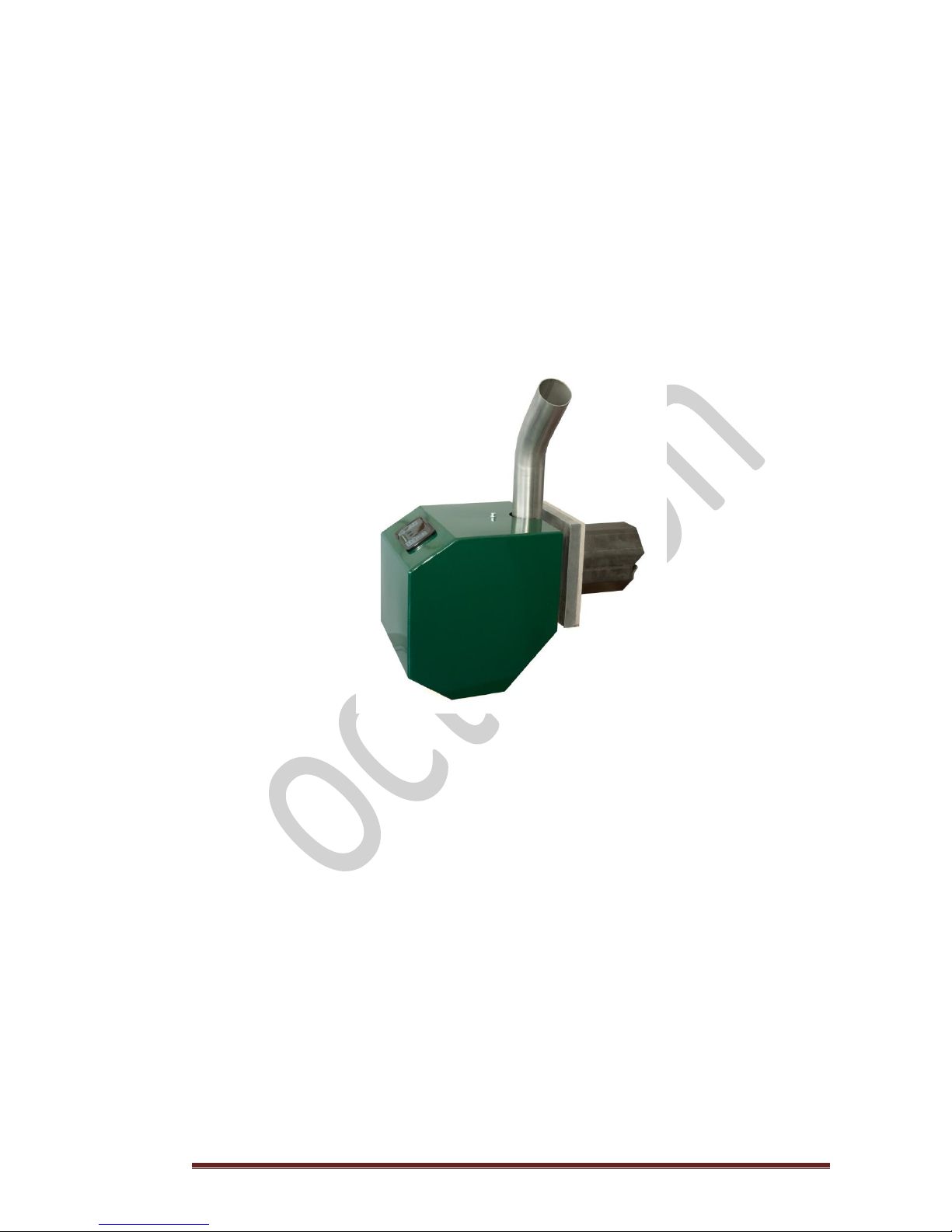
Pellet Burner
Series Octagon
Model bio 3 – Fbio 3
3’’
Page 2

octagon v2.16 Page 2
Page 3
octagon v2.16 Page 3
CONTENTS
SECTION
CONTENTS
PAGE
1
Letter of thanks
3 2 Instructions for use
4 3 Burner’s operating principles
5 4 Burning phases
7 5 Choosing the right burner
8 6 Safety rules
9
6.1
Safety installation instructions to licensed technicians
9 7 Package
10
7.1
Package contents
11
7.2
Pellet burner parts
12 8 Spare parts
13 9 Burner fuel
15
9.1
Technical characteristics of wood pellet according ΕΝ 14961-1
16
10
Fuel feeding - Auger
17
11
Fuel tank
18
12
Burner installation
19
12.1
Installation steps
19
13
Electrical installation - Sensors
20
14
Burner display screen
21
15
1st level - Configuration of the burner
22
15.1
Display symbols and keyboard buttons
22
15.2
Basic configuration of burner
24
15.2.1
Power rating
24
15.2.2
Boiler water temperature
25
15.2.3
Fuel
25
15.2.4
Time
26
15.2.5
Programming
26
15.2.6
Filling of the auger
26
16
2nd level - Configuration of the burner
28
16.1
Access to programming
28
16.1.2
Display of individual parameters of combustion regulation
29
17
Power adjustment of burner
30
18
Troubleshooting
32
18.1
Additional error notifications
33
19
Tables
34
19.1
Table 1, Configuration values, Auger-Fan with pellets of category 2
34
19.2
Table 2, Table of Parameters
36
20
Maintenance and checks to be performed by end user
37
21
Warranty
38
22
Maintenance log
40
23
Brief instructions for initial adjustments and operation
41
24
Certificates
43
25
Quality control checklist
44
Page 4

octagon v2.16 Page 4
Page 5

octagon v2.16 Page 5
1. LETTER OF THANKS
Thank you for choosing the pellet burner of OCTAGON.
We would like to reassure you for the high quality of our product which we trust will
fully satisfy your requirements.
OCTAGON will always be at your service maximizing the value of your purchase.
For a better future,
more sustainable,
more affordable.
Please read carefully the section under the heading “OPERATION OF THE BURNER” to
ensure proper understanding of the operating principles of the pellet burner.
Management & Production of OCTAGON
Page 6

octagon v2.16 Page 6
2. INSTRUCTIONS FOR USE
The device can be used by persons over eighteen (18) years of age with full physical, neurological
and mental capabilities and persons with no previous experience and skill or persons being
trained for the use of the device but always under the supervision of person responsible for their
safety.
Do not allow children to play with the device.
The cleaning of the device should not be done by children without the supervision of an adult.
Page 7

octagon v2.16 Page 7
3. BURNER’S OPERATING PRINCIPLES
First start
The pellet burner has predetermined configurations of maximum and minimum power rating by
the manufacturer.
The authorized trained technician who will fire up the burner has the option – if necessary – to
reduce the maximum power of the burner to fit the power of the boiler or a specific user’s
requirement.
Operation of the burner
First check
Once the start command is given by the user, the burner performs a series of checks to the
whole system in order to ensure that all parameters permit its smooth and safe start.
To this effect the burner checks immediately a number of parameters e.g. the water
temperature or the exhaust gas temperature. The values of all parameters should be within a
predetermined and acceptable range as indicated by the manufacturer to enable start of the
burner.
Combustion of the burner
After the controller performs the first check, the auger feeds the pellet burner with a specific
quantity of pellet and ignition is generated with the use of an electrical heating element.
Burning
When the flame sensor “detects” - within a specific time frame - that the flame’s intensity is
sufficient then the pellet burner will proceed to the BURNING PHASE aiming to the maximum
power level.
Should the flame sensor does not confirm the required intense of flame within the specific time
frame then the starting process is stopped and an “error” notification is displayed which is
accompanied with the code diagnosing the type of error (see §18 “Troubleshooting”).
Page 8

octagon v2.16 Page 8
The innovation of Octagon pellet burner bio lies with two crucial elements relating to
combustion:
a. The operation of the burner is totally proportional, within the predefined parameters,
subject to automatic adjustment of the level of power (self adjustment). In this way the
pellet burner will provide always the power required by the system and will achieve the
maximum possible fuel economy
And,
b. The pellet burner will control the burning process by the constant and excellent control
of the boiler’s backpressure and the chimney draft. The control of the fan ensures not
only the extraction of the exhaust gas but mainly minimizes the possibility of “backfire”
from the supply pipe.
Gradual reduction of combustion level
As soon as the burner achieves the predefined water temperature it will automatically reduce its
power so as to remain functional within the set temperature range and below the upper safety
limit. At this point the burner operates with the necessary, minimum power meeting the
required thermal need.
END OF BURNING
The smooth termination of burning is achieved by ensuring the complete burning of any
remaining fuel in the combustion chamber. This is achieved by continuous monitoring of the
flame through the flame sensor which drives the fan that will continue to work in order to burn
all residual pellets in the flame tube.
Thereafter, the fan continues at maximum speed for a period of time so as to clean the burning
chamber from the ashes and preparing it for the next fire up.
Page 9

octagon v2.16 Page 9
4. BURNING PHASES
Everything described in the previous chapter, OPERATING PRINCIPLES, is outlined in the cycle
below which is divided in four sections:
A. FIRE UP, yellow colour
The burner checks whether there is flame in the burning chamber, in case of a KEEP FIRE status,
so as to offer the minimum required power to the system. Whatever the status of the burning
chamber may be, the burner will proceed with full ignition of the fuel intensifying the flame until
the threshold of burning phase is reached.
B. BURNING
The power of the burner rises progressively whilst it performs constant checks to all parameters
of the combustion in order to allow the maximum desired thermal performance with utmost
economy.
C. FIRE DOWN
When the water temperature approaches the set threshold then the burner regulates POWER to
achieve balance in the system. Gradually, the reduction in burning will lead the system to KEEP
FIRE or OFF status.
D. KEEP FLAME OR OFF
The burner at this phase is put in stand-by mode either turned off or keeping the flame. In both
cases it can be put back to FIRE UP status.
OCTAGON Hellas
Page 10

octagon v2.16 Page 10
5. CHOOSING THE RIGHT BURNER
In order to make to right choice of burner - both technically and practically - you need to take
under consideration certain basic parameters:
1. The burner is designed to burn wood pellets ONLY. The use of any other type of pellet
such as agro-pellets (pellet made of agricultural by-products) without the approval of the
manufacturer is explicitly prohibited.
2. Make sure that your boiler is designed to burn pellets. The manufacturer of the boiler
will indicate the appropriate type of fuel and will provide relevant information for proper
combustion including the following:
Output power for the particular fuel. This should be equal to or less than the
maximum rated power of the burner as indicated on the name plate of the burner.
Minimum chimney draft.
Regulation of the burner’s damper.
Exhaust gas temperature.
3. Additionally, please note that:
The minimum capacity of the combustion chamber should be 0,06 m
3
in respect of
models bio 2 and 1 and 0,12 m3 in respect of model bio 3 in order to achieve the
maximum power of the burners.
For the unhindered opening of the boiler door both the door and the burning
chamber of the boiler should have minimum width as follows:
o Thirty (30) cm in respect of model bio 2
o Forty (40) cm in respect of model bio 3
The minimum length of the burning chamber should be:
o Forty (40) cm in respect of model bio 2
o Fifty two (52) cm in respect of model bio 3
The length of the flame should be at least five (5) cm below the above mentioned
values.
The space in front of the boiler should be free in an arc 90° towards the same
direction to which the door opens and at a distance of at least a hundred (100) cm to
ensure unhindered door opening when necessary.
The burner should be installed ONLY in horizontal position.
POINTS TO REMEMBER
The technician responsible for the installation and the first fire up of your burner is
obliged to provide you with a “Combustion Certificate” which includes the following:
The type of the burner
The type of the boiler
The exhaust gas temperature
The content in CO and CO2.
Page 11

octagon v2.16 Page 11
6. SAFETY RULES
The pellet burner is an electric/electronic device that operates with 230 V – 50 HZ. According to
applicable legislation its installation, connection, regulation, operation and service should be
done by trained personnel authorized by the local authorities.
It is expressly forbidden for anyone to modify parameters of 2nd level of configuration except for
trained licensed technicians.
The private individual and end user of the pellet burner may operate and adjust the burner ONLY
in so far as the basic commands of the burner are concerned and ONLY using the display and
programming touch screen situated on the metal casing of the pellet burner.
6.1. SAFETY INSTALLATION INSTRUCTIONS TO LICENSED TECHNICIANS
Please ensure that the boiler standards comply with applicable legislation. The boiler must be
connected with the hydraulic system and the chimney.
Measure the chimney draft and make sure that it is in line with the requirements of the
manufacturer of the boiler.
Please adhere to all instructions concerning start up and make sure to use only approved and
certified materials.
Never open the door of the boiler while the burner is in operation.
The burner conforms to European Directive ΕΝ 15270
and is CE marked.
ATTENTION
Always ensure that the boiler’s flame damper is
open to allow optimum level of draft.
NEVER fire up the burner when the flame damper
is closed as there is serious DANGER of the flame
returning to the burner.
Page 12
octagon v2.16 Page 12
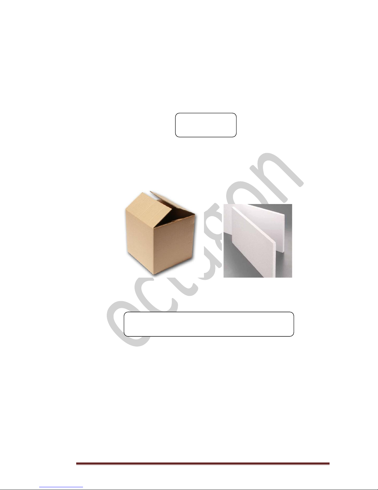
7. PACKAGE
The pellet burner will be packed in hard cardboard box of dimensions 60 cm X 40 cm X 40 cm
(Length / Width / Height) and will bear an adhesive label showing the model of the burner as
follows:
Model
Special care is given to the packing of the burner to make sure that it will be delivered to you
safely and free of any damage. The product is wrapped in thick polystyrene sheets and placed in
a plastic bag.
ALWAYS STORE THE PACKED PELLET BURNER IN CORRECT
HORIZONTAL POSITION AWAY FROM MOISTURE.
bio 2
Page 13

octagon v2.16 Page 13
7.1 PACKAGE CONTENTS
Each package contains:
o A user guide manual with information in respect of installation,
operation and maintenance.
o A burner with its metal casing and the display screen, connected with its
stainless steel burning chamber.
o A stainless steel pipe 2” for the feeding of the fuel.
o A certificate of quality control including the date of production of the
burner at the last part of the manual.
T h e a u g e r i s s u p p l i e d t o g e t h e r w i t h e a c h b u r n e r .
FOR SAFETY REASONS THE DISPLAY SCREEN IS NOT
CONNECTED TO THE ELECTRONIC CONTROL UNIT OF THE
BURNER. THE CONNECTION SHOULD BE EXECUTED BY THE
LICENSED TECHNICIAN.
DO NOT FORGET TO CHECK THAT ALL PARTS OF
THE BURNER ARE FIRMLY CONNECTED.
Page 14

octagon v2.16 Page 14
7.2 PELLET BURNER PARTS
The pellet burner consists of the following parts:
1) A steel metallic casing electrostatically painted (green).
2) An electronic display and programming touch screen.
3) A connection cable of the screen to the central control unit.
4) A stainless steel frame body with flange for fixing the burner to the boiler.
5) One (1) centrifugal fan of 40 W.
6) An electronic central control unit (plc).
7) An electric heating element of 250 W.
8) A flame sensor.
9) Electric connector.
10) A stainless steel feeding tube 2” with insulating flange.
11) A bimetallic contact thermostat, STB, with manual reset placed in the 2” stainless steel
feed tube.
12) Three (3) cable glands for the accommodation of the connection cables.
13) A high heat resistant stainless steel flame tube for the combustion of the fuel.
14) A high heat resistant stainless steel combustion rack.
15) A screw to hold the rack.
16) A mineral insulation of twenty five (25) mm for the flange.
17) Internal insulation of five (5) mm for the flame tube to the casing.
18) A boiler water temperature sensor.
19) An exhaust gas temperature sensor.
A metallic auger moving the pellets from the fuel tank to the burner via electric motor
of 50 W.
This is packed with a polyurethane flex hose to be connected with the stainless steel
feeding tube.
Page 15
octagon v2.16 Page 15
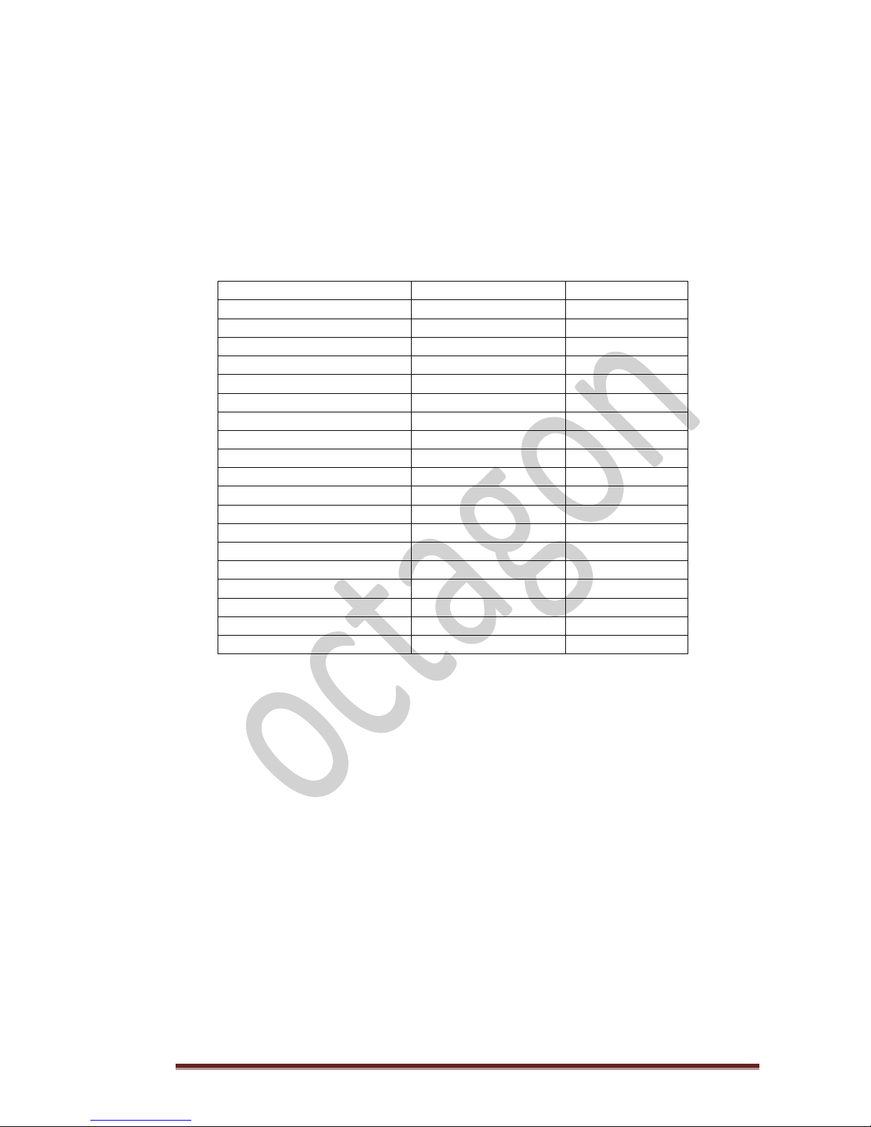
8. SPARE PARTS
The table herebelow contains a list of spare parts of a pellet burner by OCTAGON HELLAS
including relevant reference numbers. The reference number should be quoted when an order is
placed.
REFERENCE NUMBER
DESCRIPTION OF SPARE PART
Μ001-1001-1
Steel casing of pellet burner bio 2
Μ001-1001-2
Steel casing of pellet burner bio 3
D100-1100-1
Electronic touch screen LCD
D100-1200-1
Connection cable of screen to the central control unit 1 m.
D100-1200-2
Connection cable of screen to the central control unit 2,5 - 5 m.
D100-1300-1
Wall mounted stainless frame for touch screen
Ρ100-1021-1
Plastic frame for touch screen
Μ001-1100-0
Auger set series OCTAGON , 2 1.2''
Μ001-1100-1
Auger set series OCTAGON , 3''
M001-1400-1
Steel casing for auger motor bio2 & bio3
Ρ100-1011-1
PU flex hose feeding pellet 60 mm (diameter) per m
Ε100-1110-10
Auger motor series OCTAGON
Ε100-1030-1
Cable set for auger
Α100-1001-1
High heat resistant stainless steel flame tube for bio 2
Α100-1001-2
High heat resistant stainless steel flame tube for bio 3
Α100-1011-1
High heat resistant grate for bio 2
Α100-1011-2
High heat resistant grate for bio 3
A100-1021-1
Mineral insulation for the flange 25 mm (thickness) for bio 2
A100-1021-2
Mineral insulation for the flange 25 mm (thickness) for bio 3
F100-0101-2
Internal insulation gasket for flame tube 5 mm for bio 2
F100-0101-2
Internal insulation gasket for flame tube 5 mm for bio 3
A100-1101-1
Stainless steel flanged feeding tube 2’’
F100-0101-1
Insulating flange for stainless steel feeding tube 2''
Page 16
octagon v2.16 Page 16
S100-1001-1
Flame sensor BRAHMA , FC 8R
S100-1010-1
Electric heating element 250 W
S100-1020-1
Boiler water temperature sensor
S100-1030-1
Exhaust flue gas temperature sensor 1,5 m (length)
S100-1030-2
Exhaust flue gas temperature sensor 3 m (length)
S100-1050-1
Bimetallic contact thermostat with manual reset, STB , for the
2''stainless steel feeding tube
E100-1110-11
Fan with flange series OCTAGON 40 W
D100-1001-1
Electronic central control unit (plc)
Page 17

octagon v2.16 Page 17
9. BURNER FUEL
The pellet burners of OCTAGON, are designed to burn wood pellets.
The pellets are very small chips of wood along with other logging residues which are compressed
mechanically in order to take a cylindrical shape of around 6 - 8 mm diameter and less than 40
mm of length.
The type of wood used in this process as well as the percentage that each wood contributes to
the final mixture will determine a number of important parameters including the following:
Thermal output (heating power as a value of kW/kg or Kcal/kg or KJ/kg)
Combustion quality (rate of solid residues of burning process)
Cost per kg
The correct regulation of the combustion air in the pellet burner minimizes ash content and
maximizes thermal output. The acceptable rate of ash content is specified by EN 14961-1
(Chapter 7.1, page 14).
It is very important for the proper functioning of the burner as well as fuel economy that the
pellet burner to be fed with certified wood pellet that conforms to European standards and be
supplied from producers who are well established in the market.
The thermal power of wood pellets must be in excess of 4,6 kW/kg so that the final result should
satisfy all the parameters of proper combustion together with your expectations in economy.
DO NOT BUY WOOD PELLETS OF UNKNOWN ORIGIN AND QUALITY.
IT IS TO YOUR BEST INTEREST TO USE ALWAYS THE BEST QUALITY OF PELLETS.
Page 18
octagon v2.16 Page 18
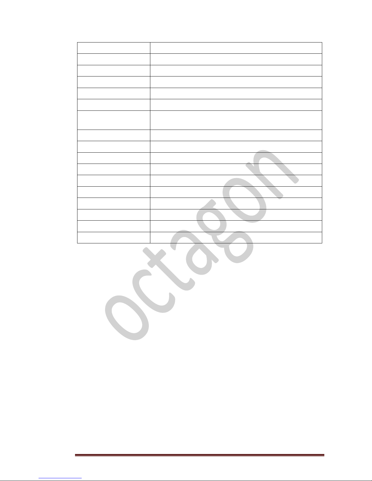
9.1 TECHNICAL CHARACTERISTICS OF WOOD PELLET ACCORDING ΕΝ 14961-1
The European standard ΕΝ 14961-1, which specifies the technical characteristics of wood pellets,
has not yet been finalized. Upon completion it will become mandatory to all European Union
member states. As at today (September 2012) every member state has its own standards.
SIZE
MEASUREMENT UNIT
VALUE
DIAMETER
mm
6 - 8
LENGTH
mm
3,15 - 40
DENSITY
kg/m3
≥ 600
FINES
w-% dry
≤ 1
MOISTURE CONTENT
w-% dry
≤ 10
ASH CONTENT
w-% dry
≤ 0,7
THERMAL POWER
MJ/kg
16,5 - 19
Sulphur
w-% dry
≤ 0,03
Nitrogen
w-% dry
≤ 0,3
Chlorine
w-% dry
≤ 0,02
Arsenic
mg/kg
≤ 1
Cadmium
mg/kg
≤ 0,5
Chrome
mg/kg
≤ 10
Copper
mg/kg
≤ 10
Mercury
mg/kg
≤ 0,1
Lead
mg/kg
≤ 10
Zinc
mg/kg
≤ 100
Nickel
mg/kg
≤ 10
Additives
%
≤ 2
Page 19

octagon v2.16 Page 19
10. FUEL FEEDING - AUGER
The feeding of the pellet burner is achieved using a metal auger which rotates via a motor and
transfers pellet from the fuel tank to the burner.
Between the feeder and the inox feeding tube of the burner, a polyurethane flex hose is used.
Relevant hose is flame retardant for safety reasons in case of gases and flames return from the
combustion chamber through the inox feeding tube to the fuel tank (reverse path). In this case
the tube will melt by the high temperature creating a disruption of the gases direction from the
burner to the fuel tank.
The slope of the auger should be within the range of 40 - 45 degrees.
Relevant slopes are achieved by OCTAGON fuel tanks of 200 and 350 litres. In case of different
slope please contact the manufacturer for instructions as this will interfere with the proper
supply of the fuel.
Never leave the fuel tank without pellets as then you will be required to fill the auger manually
(see §15.2.6 “Filling the auger”).
MAKE SURE THAT THE PLASTIC PIPE IS OUTSTRETCHED WITHOUT CURVES
THE OPERATION OF THE BURNER MAY BE INTERRUPTED
CORRECT POSITION WRONG POSITION
Minimum
height 40 cm.
Page 20

octagon v2.16 Page 20
11. FUEL TANK
The fuel tank plays an important role in the proper and undisturbed feeding of the burner.
OCTAGON has designed a fuel tank - with special interior - that fully meets the requirements of
the burner by ensuring steady and safe operation of the auger and allowing maximum utilization
of the stored pellets.
DO NOT USE HOMEMADE FUEL TANKS
AS THIS WILL JEOPARDIZE
THE PROPER OPERATION AND FEEDING OF THE BURNER
Diagram of fuel tank of 200 liters (usable volume)
Page 21

octagon v2.16 Page 21
12. BURNER INSTALLATION
12.1 INSTALLATION STEPS
1. Ensure that the boiler room is in line with local regulations paying special attention to
ventilation.
2. Ensure that the boiler is connected to the hydraulic network and that the exhaust flue
gas system is tightly connected.
3. Measure the chimney draft and make sure that it complies with the “minimum chimney
draft” according to the manufacturer of the boiler.
4. Secure the flame damper of the boiler (if any) to the proper position.
Only after having satisfied the above terms you may proceed with burner installation.
5. Remove the steel metallic casing of the burner including the display screen.
6. Ensure that the burning chamber of the burner is tightly connected to the flange of the
burner. If required, please tighten the screws.
7. Tighten the stainless steel flange of the burner against the door of the boiler.
8. Place the stainless steel feeding tube with the flange and tighten it.
9. Place the sensors of the burner:
Exhaust gas sensor to the flue duct connecting the boiler with the chimney
Boiler water temperature sensor
Other sensors
Bimetallic contact thermostat to the stainless steel feeding tube
10. Make electrical connections of the burner (see §13 “Electrical installation – Sensors”)
11. Fill the auger with pellets (see §15.2.6 “Filling the auger”)
12. Connect the flex hose feeding the pellets.
13. Connect the cable of the display screen with the electronic part of the burner.
14. Place and screw tightly the metal casing of the burner.
YOUR BURNER IS READY TO START UP
The burner regulates on its own both primary and
secondary air required for the burning process.
Page 22

octagon v2.16 Page 22
13. ELECTRICAL INSTALLATION – SENSORS
The electrical connections of the burner as well as the adjustment of the burner are only allowed
to trained licensed technicians for safety reasons. The safety electric connector of the burner has
twelve (12) numbered connections.
As soon as all cables pass through the corresponding cable glands then cables should be
connected as follows:
CONNECTION 1
POWER SUPPLY - Phase 230 V AC – 50 Hz (Live).
The polarity of the current is very important and this connection should
be connected with the phase of the current otherwise there will be a
malfunction and/or damage to the electronic board.
CONNECTION 2
POWER SUPPLY - Neutral
CONNECTIONS 3 -4
AUGER.
CONNECTIONS 5 – 6
WATER PUMP.
The current intensity of the water pump should not exceed 0,7 A
otherwise, an electrical relay should be inserted.
CONNECTIONS 7 - 8
EXTERNAL THERMOSTAT (Dry contact)
CONNECTIONS 9 - 10
SAFETY SWITCH (water’s safety thermostat )
The connections 11 and 12 will remain unused for future connections with peripheral devices to
the burner.
Install the connection line of the burner to a general switch so that the poles of the current
(L&N) can be disconnected should this be required.
CAUTION
THE EXTERNAL COMMAND OF THE BURNER (THERMOSTAT,
AUTONOMY TABLE) IS DRY CONTACT. IN CASE OF CURRENT
(230 V) YOU HAVE TO INSERT AN ELECTRICAL RELAY
SENSORS
BLACK PLASTIC = BOILER WATER TEMPERATURE SENSOR
Put some thermal oil in the boiler thermometer pocket to achieve thermal conductivity.
SILVER METALLIC = CHIMNEY SENSOR
Secure the sensor to the flue with aluminum tape or high temperature silicon.
Page 23

octagon v2.16 Page 23
14. BURNER DISPLAY SCREEN
KEYBOARD BUTTONS AND DISPLAY SYMBOLS
Alarm
Servicing
Indicator Timer Fuel
Temperature
Alarm IR Sensor Fan Time
Cleaning Power
Alarm
No
Fuel Set up
Cancel
Increase / Decrease + _
Light
Signal of operation
Power ON /OFF Enter
< Menu buttons >
Page 24

octagon v2.16 Page 24
15. 1ST LEVEL - CONFIGURATION OF THE BURNER
The 1st level of configuration is user friendly and easily accessible to the end user of the burner.
This configuration mainly introduces the end user to basic information of the device and allows
him to modify settings such as time or screen brightness.
15.1 DISPLAY SYMBOLS AND KEYBOARD BUTTONS
DISPLAY SYMBOLS
At the top of the display screen there are a number of symbols which indicate the basic
functions of the burner (Image No. 1, page 21).
The symbols are displayed in three colours:
GREEN indicating FUNCTION
RED indicating ERROR
ORANGE indicating SETTING FUNCTION
MENU < > command allows us to choose one of the “basic functions” of the burner (1st level of
configuration and operation). All basic functions are displayed in green colour in the following
order from left to right:
POWER is displayed by a “flame” symbol and the screen indicates AUTO which means that the
burner is operating automatically and proportionally in accordance with its settings.
TEMPERATURE is displayed by a “thermometer” symbol and the screen indicates the
temperature of the boiler water in οC (Celsius scale) at all times
FUEL is displayed by an “open container” symbol and the screen indicates the category of pellet
with which the burner operates i.e. 1, 2 ή 3.
Page 25

octagon v2.16 Page 25
TIME is displayed by a “clock” symbol and the screen indicates the current time in hours and
minutes i.e. 13:12.
PROGRAMMING is displayed by a “gear” symbol and the screen indicates OFF.
The programming belongs to the 2nd level of configuration of the pellet.
DESCRIPTION OF KEYBOARD BUTTONS
BUTTON
DESCRIPTION
Power ON/OFF button is used for turning the combustion system on or off.
Press and hold the button for one (1) second.
Menu buttons are used for navigating the first level menu context. The
currently selected menu context is indicated with the corresponding icon at
the top. In addition, these buttons are used in the edit mode.
Edit buttons are used for navigating the submenus and increasing /
decreasing values in the edit mode, when the selected value blinks.
Enter button is used for entering the edit mode and confirming the set values,
or selecting the additional submenus.
Cancel button is used for discarding the changes and returning up one level in
the menu. If you press and h old this button for more than three (3) seconds,
the last error or alert code is displayed.
The advanced keyboard of bio-burner is also equipped with the beeper, which provides the
keyboard feedback signals. The following sound signals are available:
Short high tone: sounds when navigating the menu and editing the settings
Long low tone: sounds in case of an invalid operation (wrong button pressed)
Long high tone: in case of and alert, this tone sounds with the user defined loudness, and in
case of an error, this tone sounds with 100% loudness. For description of alerts and errors,
refer to §18 “Troubleshooting”.
Page 26

octagon v2.16 Page 26
15.2 BASIC CONFIGURATION OF BURNER
After the electric connection is made you may proceed with the installation of the burner. By
keeping the button ON / OFF pressed for one (1) second the indication ON will be displayed on
the screen and the burner will automatically begin operation. This means that the burner will
proceed to the phase “FIRE UP”.
15.2.1 POWER RATING
The burner has been set by the manufacturer to work automatically (i.e. analog power control)
at maximum power of 35 kW/h and 70 kW/h in respect of bio 2 and bio 3 respectively.
Additionally, there is the option to operate the burner at a different power rating but relevant
adjustment can only be performed by a licensed technician using the 2nd level of configuration.
(see §15.2.5 “Programming”).
The burner could also operate at all times at a user defined (NOT analog) power rating through
appropriate adjustment at 1st level of configuration. The minimum and maximum power rating
together with intermediate values, as defined by the manufacturer, are included in the table
below:
POWER
bio 2
bio 3
P5 (Max)
35 kW/h
70 kW/h
P4
28 kW/h
56 kW/h
P3
21 kW/h
42 kW/h
P2
15 kW/h
27 kW/h
P1 (Min)
8 kW/h
12 kW/h
If you wish to reduce the maximum power rating of the burner by removing its analog feature
then you should follow the next steps:
Navigate through the MENU button < > to the POWER (flame symbol).
Press ENTER. The indication AUTO will appear on the screen blinking.
Press the EDIT buttons +, - to choose the desired power rating, 4, 3, 2, ή 1.
Press ENTER to set the desired power rating. The command will be stored and the selected
power rating will be displayed on the screen.
Page 27

octagon v2.16 Page 27
15.2.2 BOILER WATER TEMPERATURE
Navigate through the MENU button < > to the TEMPERATURE (thermometer symbol).
PRESS ENTER. The screen will show the predefined boiler water temperature.
Press the EDIT buttons +, - to choose the desired boiler water temperature.
Press ENTER to set the desired boiler water temperature. The command will be stored and
you can move on.
15.2.3 FUEL
The FUEL button indicates the category of the pellet that bio burner is adjusted to.
The categories of the pellet are three (3) :
Category 1: Pellet with thermal power 5,4 kW/kg
Category 2: Pellet with thermal power 5 kW/kg
Category 3: Pellet with thermal power 4,6 kW/kg
If you wish to change category pellet then:
Navigate through the MENU button < > to the FUEL (open container symbol).
Press ENTER. The number indicating the current pellet category will appear on the screen
blinking.
Press EDIT buttons +, - to choose the desired category.
Press ENTER to set the desired pellet category. The command will be stored and the selected
pellet category will be displayed on the screen.
All burners of OCTAGON HELLAS are initially
adjusted to pellet Category 2
The burner will adjust the AUGER and FAN to the new
parameters automatically.
You simply need to define the pellet category in use.
Page 28

octagon v2.16 Page 28
15.2.4 TIME
Navigate through the MENU button < > to the TIME (clock symbol).
Press ENTER. The indication 00:00 will appear on the screen. The first part will be blinking.
Press the EDIT buttons +, - to insert the time in hours (0 to 24).
Press the Menu button < > to move to the second part.
Press the EDIT buttons +, - to insert the time in minutes (0 to 60).
Press ENTER to set the time. The command will be stored and you can move on.
15.2.5 PROGRAMMING
The programming has thirteen (13) submenus. These are:
1
OFF, useful only to the technician. (Always set to OFF).
2
SCREEN BRIGHTNESS (1 to 5)
3
CHANGING DISPLAY STATUS OF LCD SCREEN
Press 1 for continuous rotation of display values
Press 2 for screen display of boiler water temperature
Press 3 for screen display of the time / water temperature
4
BEEPER VOLUME
5
HARDWARE TYPE AND SCREEN, useful only to the technician.
6 MANUAL ACTIVATION OF AUGER
A particularly useful command for the filling of auger with fuel either at first start
up or after emptying the fuel tank.
7
UNLOCK OF PROGRAMMING to new parameter settings
This is ONLY allowed to a qualified licensed technician giving him access to
modify predefined settings Νο 8 to 13
8
SYSTEM PARAMETERS e.g. fan speed
9
d In , to be adjusted only with manufacturer’s approval
10
Α In, display of sensors’ current values (see §16.1.2)
11
DIGITAL OUTPUT, to be adjusted only with manufacturer’s approval
12
STATISTICS OF BURNER’S USE (manufacturer)
13
ERROR LOG REPORT (manufacturer)
Navigate through the MENU button < > to the PROGRAMMING (gear symbol).
The indication OFF will appear on the screen.
Press EDIT buttons +, - to choose the setting you wish to modify e.g. [ 2 ]* and press ENTER.
A number indicating the screen brightness e.g. 3 will appear on the screen.
Press EDIT buttons +, - to choose the desired brightness and press ENTER.
The end user is only allowed to modify parameter settings 2, 3, 4 and 6 at the 1st level of
configuration of the burner.
Page 29

octagon v2.16 Page 29
15.2.6 FILLING THE AUGER
The filling of the auger is performed after you have first disconnected the flex hose from the
stainless steel tube of the burner and place a bucket to its end to collect the outgoing pellets.
Those pellets can be placed back to the fuel tank once you have finished.
Navigate through the MENU button < > to the PROGRAMMING (gear symbol).
The indication OFF will appear on the screen.
Press the EDIT buttons +, - to go to number [ 6 ] and press ENTER.
The screen will display horizontal dots - - - - .
Keep ENTER button pressed constantly while the dots are blinking.
The auger starts to operate and transfers the pellets to the burning chamber. The duration
of this operation is approx. 30 seconds (30’’). On completion of the operation the auger
stops and OFF indication appears on the screen. This process is repeated one more time by
keeping the ENTER button pressed and wait for another thirty seconds (30’’). This will ensure
that auger has been filled successfully.
When OFF indication appears on the screen again you can move on.
To make sure that the auger has been fully loaded with
pellet please fill in the fuel tank with minimum three
(3) bags of pellet (45 kg in total) and activate the auger
for at least ten (30) minutes.
Page 30

octagon v2.16 Page 30
16. 2nd LEVEL - CONFIGURATION OF THE BURNER
The 2nd level of configuration of the burner is ONLY allowable to trained licensed technicians.
Access to this level of configuration is strictly forbidden to end users as there is a serious risk of
deregulation of the burner.
16.1 ACCESS TO PROGRAMMING
Navigate through the MENU button < > to the PROGRAMMING (gear symbol).
The indication OFF will appear on the screen.
When indication OFF appears on the screen and you press ENTER then the indication OFF will start blinking.
Press EDIT buttons +, - to move to indications Hi or Lo.
Hi: enables deactivation of ON/OFF button
Lo: enables deactivation of ENTER button
Above options are used only by the service personnel in case of cleaning the screen and/or keyboard of the
burner etc.
Press once any of the EDIT buttons +, - a number in brackets will appear on the screen
e.g. [ 2 ]
Press the EDIT button + to go to number [ 7 ] and press ENTER.
A four (4) digit number will appear. Add up the four digits plus one e.g. number [ 2025 ] =
= 9 +1 = 10 and press ENTER.
Press EDIT buttons +, - to insert the sum (in our example above the sum is 10) and press
ENTER. The ON indication will appear on the screen.
Now you have full access to the 2nd configuration level including the parameter settings
of burning allowable by the manufacturer.
Press EDIT buttons +, - go to number [ 8 ] and press ENTER. When “Par” indication appears
on the screen press ENTER. The screen will display P 000.
Press the EDIT buttons+, - to insert the code of the parameter you wish to change e.g.
number 28 refers to the Fan speed 5 (max. speed).
Press ENTER. The screen will display a blinking number e.g. 155 indicating the fan speed.
Press the EDIT buttons+, - to choose the new fan speed e.g. 156 and press ENTER. The new
fan speed 5 will be 156 i.e. higher than the previous setting.
See Table of parameters in Table 2, §19.2
Page 31

octagon v2.16 Page 31
16.1.2. DISPLAY OF INDIVIDUAL PARAMETERS OF COMBUSTION
REGULATION
The screen provides us with information on the current values of the various parameters.
It is particularly useful during the first fire up and when you wish to perform a system check.
Repeat steps detailed in previous section to go to setting number 10 and press ENTER.
Press EDIT buttons +, - to display values for the following parameters:
t 03, EXHAUST GAS TEMPERATURE
t 04, for the manufacturer
t 01, BOILER WATER TEMPERATURE
t 02, for the manufacturer
t 05, for the manufacturer
F 01, FUEL TANK SENSOR (if any)
Press, BURNING CHAMBER PRESSURE SENSOR (BURNING CHAMBER DRAFT)
Page 32

octagon v2.16 Page 32
17. POWER ADJUSTMENT OF BURNER
Before you change the maximum power of the burner you should first understand its analog
function and as an example we will look into the operation of model bio 2 of maximum power
(Ρ5), nominal power 35 kW/h and minimum power (Ρ1) of 8 kW/h.
In analog power the intermediate power ratings Ρ2, Ρ3, Ρ4 are automatically defined in such a
way that the distance between two consecutive power ratings is always equal.
The minimum power Ρ1 remains unchanged, unless you wish to modify it.
E.g. When you wish to reduce power rating from 35 down to 32 kW/h , the burner will
automatically redefine the remaining three (3) power ratings by calculating the distance of the
“step” the as follows = (32-8)/4 = 6
In the above example the power ratings are redefined as follows:
Ρ5 = 32 kW/h (new default value)
Ρ4 = 26 kW/h
Ρ3 = 20 kW/h
Ρ2 = 14 kW/h
Ρ1 = 8 kW/h
POWER REDUCTION
In order to reduce the power of the burner you should also redefine the values of the AUGER
and FAN at maximum power 5. To this effect you need to consult two tables:
o TABLE 2, TABLE OF PARAMETERS (see §19.2) for selection of the parameter to be
modified
o TABLE 1, CONFIGURATION VALUES, AUGER-FAN WITH PELLETS OF CATEGORY 2
(see §19.1) for reference values of the AUGER and FAN.
The parameter that defines the AUGER at POWER 5 is No. 18,
Whereas,
The parameter that defines the FAN at POWER 5 is No. 28.
After unlocking and accessing the PROGRAMMING (see §16.1) the ON indication will appear on
the screen.
Press EDIT buttons +, - go to number [ 8 ] and press ENTER. When “Par” indication appears
on the screen press ENTER. The screen will display P 000.
Press the EDIT buttons+, - to insert the code of the parameter you wish to change
e.g. number 28 refers to the Fan speed 5 (max. speed).
Press ENTER. The screen will display a blinking number e.g. 145 indicating the fan speed.
Press the EDIT buttons+, - to choose the new fan speed e.g. 138 and press ENTER.
The new fan speed 5 will be 138 i.e. lower than the previous setting.
In the same way you may redefine the value of AUGER in order to operate the burner at a
default power rating.
Page 33

octagon v2.16 Page 33
The values of the fan in TABLE 1 (see §19.1) are indicative and may need to
be revised by you.
Each system “burner -boiler-chimney” has its own characteristics and it
might require new adjustments of fan values. The shortage of air fan may
cause - in addition to poor combustion – an overload of fuel in the burner’s
flame tube and malfunction of the whole system.
To avoid this situation ALWAYS use flue gas measuring instruments at
first fire up of the burner.
Page 34
octagon v2.16 Page 34
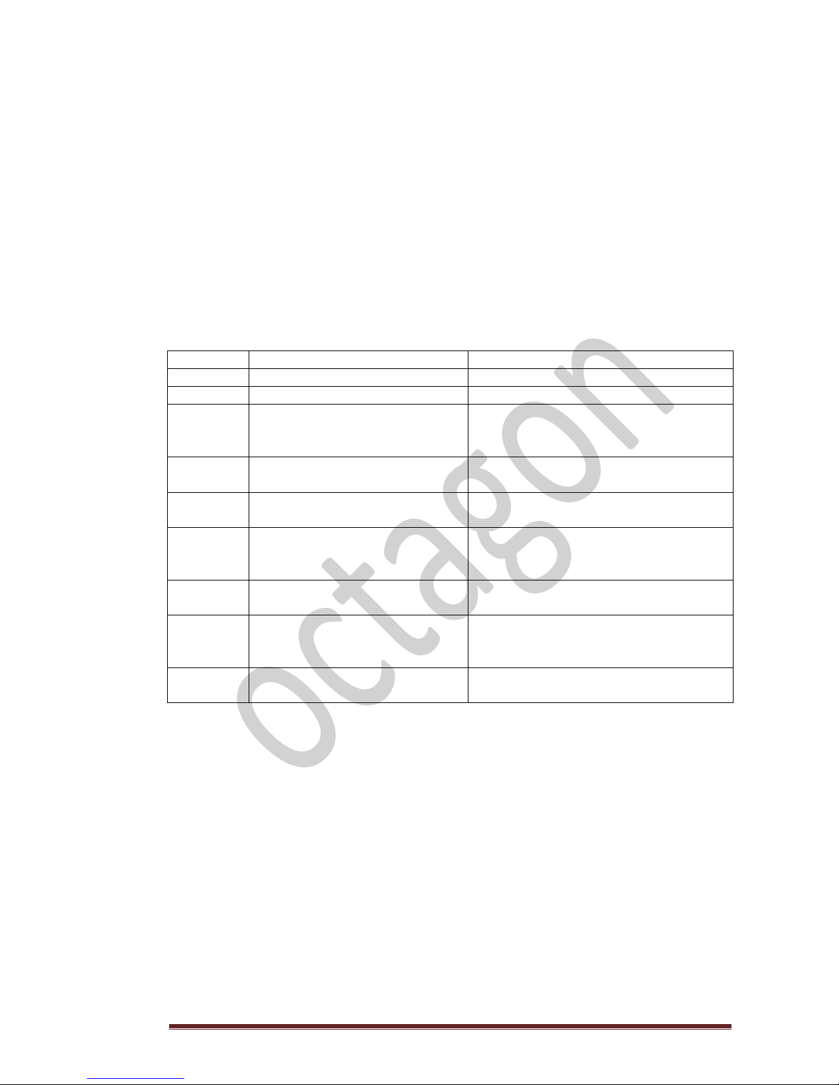
18. TROUBLESHOOTING
The keyboard of the burner provides notifications and warnings for alerts and errors,
which can occur during operation. The alarm icons indicate a problem. An alert
notification is indicated with the blinking icons, errors are indicated with continuously lit
icons. In case of an alert, the combustion system is still operational, in case of an error
the combustion system is seriously malfunctioning and the service personnel should be
contacted.
Each alert and error has a code, which can be used to identify the problem. To display
the code, press and hold the Escape button. In case there is no information on the
alert/error code, the display shows:
CODE
INDICATION
CAUSE / SOLUTION
Α001
Icon NO FUEL is blinking
Refill the fuel container.
Icon NO FUEL is on
A. Shortage of fuel in the fuel container.
B. Improper fuel (high humidity),
C. Wrong installation of auger.
Α002
Icons of CLEANING and SERVICE
blinking simultaneously
Time to service is up. Call service personnel
for maintenance of the burner.
Α003
Icon CLEANING is blinking or on
The burning chamber or chimney are dirty
and require cleaning.
Α004
Icon SERVICE is on
Call service personnel to change the
battery as it is getting low. The burner is
still operational.
Α005
Icon SERVICE is blinking
The fan sensor malfunctioned. Call the
service personnel.
Α006
Icons NO FUEL and SERVICE are
blinking
Burning chamber or fuel container door is
open. Check and close the burning
chamber or fuel container door
Α007
Icon SERVICE is blinking
The pressure sensor malfunctioned. Call
the service personnel.
Page 35
octagon v2.16 Page 35
18.1 ADDITIONAL ERROR NOTIFICATIONS
Indication: Icon SERVICE is on
The combustion system malfunctioned and is not operational.
This can be due to:
Code E001: Keyboard error
Code E002: IR communication error
Code E003: RF communication error
Code E004: MB communication error
Code E101: Fire error or water overtemperature
Code E105: NTC2 error
Code E106: NTC3 error
Code E107: TC2 error
Code E108: Security switch error (STB safety thermostat is triggered, press to reset)
Code E109: Pressure switch error (safety switch between contacts 9 – 10 is triggered)
Code E110: NTC1 error
Code E111: TC1 error
Code E112: Fuel overtemperature
Code E115: General error
Solution: Note the error code and contact the service personnel
During power supply fail, the settings of the burner remain active due to internal battery.
In case of a power supply failure internal electronics operate as follows:
DURATION OF POWER
SUPPLY FAILURE
OPERATION BEFORE THE POWER
SUPPLY FAILURE
OPERATION AFTER THE POWER SUPPLY
FAILURE
LESS THAN TWO (2)
MINUTES
FIRE UP PHASE
The burner continues normally.
BURNING PHASE
The burner checks the air / water
temperature and continues in the
BURNING PHASE, or restarts in the FIRE UP
phase.
OFF
OFF
MORE THAN TWO (2)
MINUTES
FIRE UP PHASE
The burner continues normally.
BURNING PHASE
The burner checks the flue gases
temperature. If the flue gases temperature
dropped below predefined value of
PARAMETER 56, the combustion system
restarts in the FIRE UP phase, otherwise it
continues in the BURNING phase.
OFF
OFF
Page 36

octagon v2.16 Page 36
19. TABLES
19.1 TABLE 1 3’’ AUGER
CONFIGURATION VALUES, AUGER-FAN WITH PELLETS OF CATEGORY 2,
HEATING POWER = 5 kW/kg
400 gr/min
POWER
ON
AUGER
VALUE
FAN VALUE
5
kW/h
Kw*h/kg
bio3
8 8 9 9
10
10
11
11 12
12
104
13
13
105
14
14
107
15
15
108
16
16
110
17
17
111
18
18
112
19
19
114
20
20
115
21
21
117
22
22
118
23
23
119
24
24
121
25
25
122
26
26
124
27
27
125
28
28
126
29
29
128
30
30
129
31
31
131
32
32
132
33
33
133
34
34
135
35
35
136
36
36
138
37
37
139
38
38
140
39
39
142
40
40
143
41
41
145
Page 37

octagon v2.16 Page 37
42
42
146
43
43
147
44
44
149
45
45
150
46
46
151
47
47
153
48
48
154
49
49
156
50
50
157
51
51
158
52
52
160
53
53
161
54
54
163
55
55
164
56
56
165
57
57
167
58
58
168
59
59
170
60
60
171
61
61
172
62
62
174
63
63
175
64
64
177
65
65
178
66
66
179
67
67
181
68
68
182
69
69
184
70
70
185
If you are using pellet of a different category to that of the burner, you should
make the appropriate selection using the display and programming touch
screen.
The burner will AUTOMATICALLY adjust the necessary parameters in line with
the selected category of the pellet.
Ensure that fan is operating at the correct speed using measurement
instruments.
Page 38

octagon v2.16 Page 38
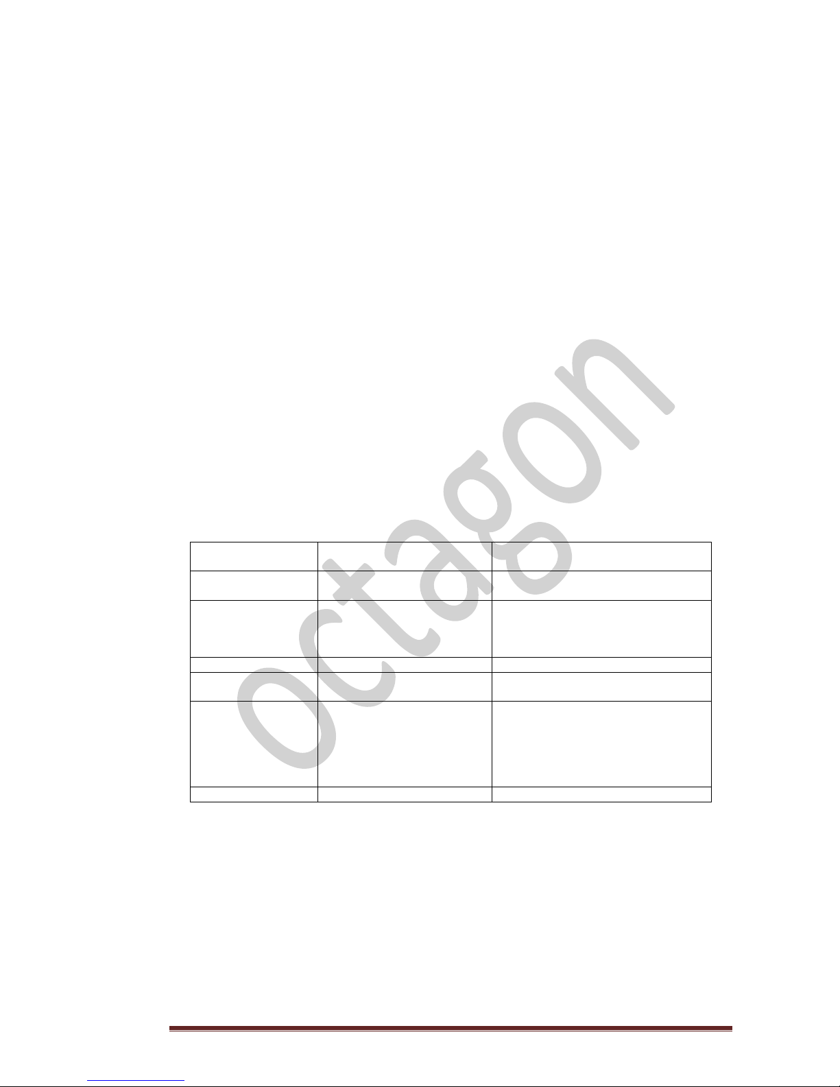
19.2. TABLE 2
TABLE OF PARAMETERS
In so far as the 2nd level of configuration is concerned access to the parameters included in the
table below is allowed. The remaining parameters belong to 3rd level of configuration and can be
modified only in liaison with and subject to agreement of the manufacturer.
PARAMETER
DESCRIPTION
INDICATIVE
VALUE OF
PARAMETER
bio 2
3
Heat Up Phase Feeder OFF
Time: 0,5’’second
5
4
Heat Up Phase Feeder ON
Time: 11,5’’ seconds
115
10
Power 1 = Feeder ΟΝ
12
18
Power 5 = Feeder ΟΝ
38
19
Fan Speed in FIRE STOP sequence
97
20
Fan speed in TEST FIRE sequence
98
24
Fan speed at POWER 1
95
28
Fan speed at POWER 5
145
50
Difference of degrees at start up of burner (51-50)
5
51
Desired Water / Air Temperature of boiler water
75
53
Safety limit of boiler water temperature (51+53)*
5
67
Water pump turn ON temperature in (oC).
35
68
Water pump turn OFF temperature in (oC).
30
70
Heat Up sequence duration (in seconds)
55
92
Defines one of the three pellets fuel quality types
2
IMPORTANT
If the boiler water temperature exceeds the safety limit set (sum of parameters 51 and 53
plus 1 oC) for more than one (1) minute the burner will automatically switch to FIRE STOP phase.
Page 39

octagon v2.16 Page 39
20. MAINTENANCE AND CHECKS TO BE PERFORMED BY END USER
As with all electronic devices, the burner also requires maintenance and cleaning service
annually in order to ensure long term operability as well as optimum fuel economy. Do not
neglect the annual service, it is possible that malfunctions may go unnoticed for several time
leading to fuel wastage and costly damages.
WEEKLY CLEANING
The end user has also the obligation to inspect frequently the combustion system and keep both
the boiler and the flame tube of the burner clean from ashes and combustion residues. The
frequency shall be determined empirically since each system or type of pellet produces different
wastage in solid form (ashes etc). We recommend that cleaning be performed at least twice (2) a
week in the beginning. During these weekly cleanings you should:
A. Remove all ashes from the interior of the boiler as well as the exhaust gas outgoing
routes using a special brush.
B. First unscrew the bolt holding the combustion grate and then remove it cleaning any
ashes and solid combustion residues.
C. Check inside the flame tube and remove any visible ashes and solid combustion
residues. Place back the combustion grate in position and tighten the screw again. Close
the door of the boiler. Your system is ready to operate.
MONTHLY CLEANING
Once a month we recommend that you clean:
D. The inclined metallic, stainless steel surface where pellet is loaded. Remove the plastic
tube with your hands, unscrew the stainless steel feeding tube 2’’ and clean with a cloth
the angled surface of the burner that leads to the burning chamber. You can also use a
flat metallic scraper.
E. Detach the plastic tube and shake it well so that any dust and debris that may have been
deposited inside the tube to be removed.
F. Unscrew and detach the flame sensor from the body of the burner. Check the glass
surface and wipe it thoroughly with a dry cloth of soft texture (not paper).
ANNUAL CLEANING
G. Once a year and before the beginning of winter, clean the fuel tank from any dust and
pellet deposits. It is essential that the fuel tank always contains clean and dry pellet. If
moisture is present in pellet then do not use it as it is unsuitable for combustion.
H. Make sure by a visual check that the system “burner – boiler – chimney” is fully
tightened. Otherwise please call immediately the service technician to repair the system.
Page 40

octagon v2.16 Page 40
Page 41

octagon v2.16 Page 41
21. WARRANTY OF PELLET BURNER OCTAGON
The European Directive 99/44/CE, sets out the specific responsibilities and obligations of the ultimate seller of the
product to the ultimate buyer for any possible defects. The European Directive can be found on the website at:
http://europa.eu/legislation_summaries/consumers/protection_of_consumers/l32022_en.htm
ΟCTAGON, is not the ultimate seller of the pellet burner; however, it accepts and undertakes the responsibility of the
ultimate seller through its additional warranty granted to OCTAGON HELLAS approved and certified sales network.
SCOPE AND DURATION OF THE WARRANTY
OCTAGON hereby guaranties the good operation of the product sold and agrees to provide spare parts free of charge
for the purpose of repairing any defective part of the burner for a period of twenty four (24) months after the date of
delivery to the ultimate buyer.
As the date of delivery shall be considered the date included in the proof of purchase (Receipt or Invoice) and MUST
accompany this warranty.
The purchase of this product should have taken place within three (3) years from the date of production as included in
the special labelling of the burner (the adhesive label on the casing of the burner).
WHEN IS THE WARRANTY VALID
The warranty is hereby granted subject to the following prerequisites:
The installation of the burner must be carried out by a licensed technician in accordance with local authority
regulations, good engineering practices and the technical manual of the manufacturer.
The burner must undergo proper service by specialized personnel and an entry be made accordingly in the
Maintenance log, included herebelow, and be signed.
The actual duration of the warranty will not be altered by intermediate service repairs.
EXCLUSIONS
This warranty will NOT cover:
Cost of carriage of the spare parts and repair works.
Damage or wear as a result of violent acts on the burner or malfunction of the power supply.
Damage caused as a result of substandard fuel quality and/or unsuitable chimney.
Incorrect installation by unlicensed technicians.
Non compliance with local authority regulations, good engineering practice and installation instructions of
the manufacturer.
Non fulfillment of the annual service.
Use of spare parts not approved by the manufacturer.
Natural forces and disasters.
RESPONSIBILITY
The licensed technician is totally and exclusively responsible for installation and compliance with local
authority regulations, good engineering practice and installation instructions of the manufacturer.
The terms of this warranty are unique and nobody can alter them, add or remove any part thereof.
This warranty is a supplement to and does not replace the European Directive 99/44/CE.
This guaranty will be validated after it has been completed and a copy be sent to the representative firm of your
country within 10 days from the date of purchase of the burner.
MODEL : DATE OF PURCHASE :
SERIAL NUMBER :
SIGNATURE AND STAMP OF THE SELLER SIGNATURE OF THE BUYER
Page 42

octagon v2.16 Page 42
Page 43

octagon v2.16 Page 43
22. MAINTENANCE LOG
SECTION
DATE
NAME OF TECHNICIAN
REMARKS
SIGNATURE
1st
2nd
3rd
4th
5th
Page 44

octagon v2.16 Page 44
23. BRIEF INSTRUCTIONS FOR INITIAL ADJUSTMENT AND OPERATION
1. ELECTRICAL CONNECTION
CONNECTION 1
POWER SUPPLY - Phase 230 V AC – 50 Hz (Live).
The polarity of the current is very important and this connection should
be connected with the phase of the current otherwise there will be a
malfunction and/or damage to the electronic board.
CONNECTION 2
POWER SUPPLY - Neutral
CONNECTIONS 3 -4
AUGER.
CONNECTIONS 5 – 6
WATER PUMP.
The current intensity of the water pump should not exceed 0,7 A
otherwise, an electrical relay should be inserted.
CONNECTIONS 7 - 8
EXTERNAL THERMOSTAT (Dry contact)
CONNECTIONS 9 - 10
SAFETY SWITCH (e.g. open boiler door sensor)
2. FILLING OF THE AUGER 1
ST
LEVEL CONFIGURATION
BUTTON
INDICATION
SCREEN DISPLAY
>
PROGRAMMING
OFF + [ 6 ]
[ 6 ]
ENTER
- - - - - - - -
Keep pressed ENTER button to start the filling of the auger in process circles of thirty second
(30’) each. On completion of each circle the indication OFF appears on the screen. Repeat the
process cycle as required.
3. SELECTION OF PELLET CATEGORY (only if pellet is not 5kW/kg)
BUTTON
INDICATION
SCREEN DISPLAY
< >
FUEL
2
ENTER 2
+, -
1 ή 3
SELECTED VALUE
ENTER
SELECTED VALUE
4. ACCESS TO PROGRAMMING, 2
nd
LEVEL CONFIGURATION
BUTTON
INDICATION
SCREEN DISPLAY
< >
PROGRAMMING
OFF
ENTER OFF + [ 7 ]
[ 7 ]
ENTER
4-DIGIT NUMBER
Add up the four digits plus one
BUTTON
INDICATION
SCREEN DISPLAY
ENTER
SUM
SUM
ENTER ΟΝ
You have now access to 2nd level configuration.
Page 45

octagon v2.16 Page 45
5. MODIFICATION OF THE MAXIMUM POWER OF THE BURNER IN TWO STEPS
5.1. ADJUSTMENT OF FAN SPEED, 2
nd
CONFIGURATION LEVEL
The speed levels per power rating are subject to the following parameters:
FAN SPEED
PARAMETER
Fan speed during phase FIRE STOP
19
Fan speed during phase TEST FIRE
20
Fan speed at Power 1
24
Fan speed at Power 5
28
ADJUSTMENT OF SPEED (CONTINUATION OF Νο 4), ACCESS TO PROGRAMMING
BUTTON
INDICATION
SCREEN DISPLAY
ΟΝ
+, -
PARAMETERS
[ 8 ]
ENTER
PARAMETER SETTINGS
Par - - - -
+, -
PARAMETER SETTINGS
DESIRED PARAMETER
ENTER
SELECTED VALUE
5.2. ADJUSTMENT PELLET FEEDING-AUGER, 2
nd
CONFIGURATION LEVEL
This procedure is the same as with the adjustment of the fan.
By adjusting only the ON time of the auger, the burner will calculate automatically the OFF time.
Choose parameter.
AUGER OPERATION
PARAMETER
Power 1 = Auger ON
10
Power 5 = Auger ΟΝ
18
Page 46

octagon v2.16 Page 46
24. CERTIFICATES
Declaration of conformity
Manufacturer : OCTAGON
Address : Koumoundourou 53 – 182 33 Attiki –
Hellas
declares that this unit is complies with the :
• EN 60335-1:2012 , EN 60335-2-102:2006
+A1:2010
Harmonized to the LVD European directive
2006/95/EC (Low voltage Directive)
• EN 61000-6-1:2007, EN 61000-6-3:2007
Harmonized to the EMC European directive
2004/108/EC
• EN 15270:2007
Quality Manager
Dimitris Papakonstantinou
CЄ12
Page 47

octagon v2.16 Page 47
25. QUALITY CONTROL CHECKLIST
We herby confirm that the burner passed successfully all manufacturing steps
and quality control tests and is delivered to you ready to use.
MODEL OF BURNER ………………………………………………
POWER RATING kW/h
Ρ5……..
Ρ4……..
Ρ3……..
Ρ2……..
Ρ1……..
Electronic controller
Touch screen bio-burner
Boiler water temperature sensor
Flue gas temperature sensor
Flame sensor
Bimetallic safety thermostat
Heating element
Fan
Auger motor
Electric connections
Metallic parts
DATE OF PRODUCTION: …………………………….
PRODUCTION ENGINEER: ………………………………………………………………...
 Loading...