

Page 1

Cosmo 3D
™
Programmer’s Guide
Document Number 007-3445-002
Page 2

CONTRIBUTORS
Written by George Eckel
Illustrated by Dany Galgani and Martha Levine
Production by Carlos Miqueo
Engineering contributions by Brian Cabral, John Rohlf, Brad Grantham, Chris
Tanner, Rich Silba, Tonia Spyridi, Michael Jones, Trina Roy, Chris Walker
St. Peter’s Basilica image courtesy of ENEL SpA and InfoByte SpA. Disk Thrower
image courtesy of Xavier Berenguer, Animatica.
© 1998, Silicon Graphics, Inc.— All Rights Reserved
The contents of this document may not be copied or duplicated in any form, in whole
or in part, without the prior written permission of Silicon Graphics, Inc.
RESTRICTED RIGHTS LEGEND
Use, duplication, or disclosure of the technical data contained in this document by
the Government is subject to restrictions as set forth in subdivision (c) (1) (ii) of the
Rights in Technical Data and Computer Software clause at DFARS 52.227-7013
and/or in similar or successor clauses in the FAR, or in the DOD or NASA FAR
Supplement. Unpublished rights reserved under the Copyright Laws of the United
States. Contractor/manufacturer is Silicon Graphics, Inc., 2011 N. Shoreline Blvd.,
Mountain View, CA 94043-1389.
Silicon Graphics, the Silicon Graphics logo and OpenGL are registered trademarks,
and Cosmo 3D, ImageVision, Inspector, OpenGL Optimizer, Open Inventor, and
Performer are trademarks, of Silicon Graphics, Inc. Java is a registered trademark of
Sun Microsystems, Inc.
Cosmo 3D™ Programmer’s Guide
Document Number 007-3445-002
Page 3

Contents at a Glance
List of Figures xxi
List of Tables xxiii
About This Guide xxv
What This Guide Contains xxv
Related Reading xxvii
Who Should Read This Guide xxvii
What You Should Know Before Reading This Guide xxvii
Suggestions for Further Reading xxvii
Style Conventions xxviii
1. Getting Started with Cosmo 3D 1
Understanding a Cosmo 3D Scene Graph 2
Scene Graph Base Classes 2
Scene Graph Construction Classes 7
Classes That Determine How Things Are Drawn 12
Classes defining Geometric Objects 13
Steps for Creating and Displaying a Simple Scene Graph 13
2. Creating Geometries 15
Geometry Terminology 16
Using Large Geometries 16
Creating csGeoSet Objects 17
csGeoSet Attributes 20
Setting Attributes 22
Cosmo 3D-Derived csGeoSet Objects 30
iii
Page 4

Contents at a Glance
3. Specifying the Appearance of Geometries 35
csContext Overview 35
Changing the Context 39
Using csAppearance 40
Applying Textures to Geometries 42
Material Settings 51
Shade Model Settings 53
Transparency Settings 53
4. Scene Graph Nodes 55
What Is a Node 56
Leaf Nodes 57
Group Nodes 58
Setting the Values in Scene Graph Nodes 61
5. Building a Scene Graph 65
Creating Scene Graphs 66
Diagramming Scene Graphs 69
Altering Scene Graphs 73
Loading a VRML Scene Graph 74
Saving Scene Graphs 75
Troubleshooting Scene Graph Construction 75
6. Placing Shapes in a Scene 77
Creating a Sense of Depth 77
Transforming Shapes to New Locations, Sizes, and Orientations 79
7. Traversing the Scene Graph 83
Scene Graph Actions 83
The Order In Which Actions Are Passed Between Nodes 86
8. Lighting and Fog 89
Using Lights in Scenes 89
Limiting the Scope of Lights 92
Using Fog in Scenes 93
iv
Page 5

9. Viewing the Scene 97
Setting the Screen Display of the Scene 97
csCamera 99
csOrthoCamera 101
csPerspCamera 101
csFrustumCamera 105
10. Scene Graph Engines 107
Engines 107
Engines that Interpolate Values 110
Engines That Change Shapes 117
11. Sensors 121
csTimeSensor 122
csSphereSensor 126
csPlaneSensor 130
csTouchSensor 134
12. User Interface Mechanisms 137
Creating a csWindow 137
Handling User Input 139
Selecting Screen Objects 140
Creating Your Own Window 143
Contents at a Glance
13. Multiprocessing 145
Implementing Multiprocessing 146
Thread Blocking 148
Multithreaded Example 150
14. Optimizing Rendering 151
Face Culling 152
Back Patch Culling 152
Culling the View Frustum 160
Level of Detail Reduced for Performance 160
Performance Programming Techniques 163
v
Page 6

Contents at a Glance
15. Adding Sounds To Virtual Worlds 167
Overview 168
How to Play a Sound File 173
Specifying Audio Files 174
Playing Sound in Immediate Mode 177
A. Cosmo Basic Types 179
Array Storage Class Types 180
Vector Classes 183
Bounding Volumes 187
Field Classes 188
Other Math Classes 191
B. Cosmo 3D Sample Application 193
Cube.cxx Explained 195
Scene Graph for Cube.cxx 203
C. Cosmo 3D Class Hierarchy 209
Index 215
vi
Page 7

Contents
List of Figures xix
List of Tables xxi
About This Guide xxiii
What This Guide Contains xxiii
Related Reading xxv
Who Should Read This Guide xxv
What You Should Know Before Reading This Guide xxv
Suggestions for Further Reading xxv
Style Conventions xxvi
1. Getting Started with Cosmo 3D 1
Understanding a Cosmo 3D Scene Graph 2
Scene Graph Base Classes 2
The csObject Class 3
Reference Counting 3
Runtime Typing 4
The csContainer Class 5
The csField Class 5
Field Access 5
Single-Item and Multi-Item Fields 6
The csNode Class 6
Scene Graph Construction Classes 7
The csGroup Class 8
The csTransform Class 9
The csShape Class 11
The csAppearance Class 11
The csGeometry Class 11
vii
Page 8

Contents
Classes That Determine How Things Are Drawn 12
csContext 12
The csEnvironment Classes 12
Classes defining Geometric Objects 13
Steps for Creating and Displaying a Simple Scene Graph 13
2. Creating Geometries 15
Geometry Terminology 16
Using Large Geometries 16
Creating csGeoSet Objects 17
csGeoSet Fields 19
Setting the Number of Primitives 19
csGeoSet Attributes 20
Attribute Bindings 20
Setting Attribute Bindings 21
Setting Attributes 22
Indexing Attributes 23
When to Index Attributes 24
Specifying Attributes 26
Using More Specific Attribute Arrays 26
Indexing Attributes 28
Setting Attributes Example 28
Editing Attribute Arrays 29
Cosmo 3D-Derived csGeoSet Objects 30
Using csPointSet 30
Using csLineSet 31
Using csIndexedLineSet 31
Using csLineStripSet 31
Using csTriSet 31
Using csTriFanSet 32
Using csTriStripSet 32
Using csPolySet 33
Using csQuadSet 33
Using csIndexedFaceSet 33
viii
Page 9

3. Specifying the Appearance of Geometries 35
csContext Overview 35
State Machine 36
Inheritance Mask 36
Accessing States 37
What Modifies the Graphics State? 38
Traversal Order 38
csContext in Multi-threaded Programs 38
Overriding Appearances and Geometry Properties with csContext 39
Making the Screen One Color 39
Changing the Context 39
Using csAppearance 40
Inheriting Appearance Values 40
Setting Appearance Fields Locally 40
Lazy Updating of Appearance Values 41
Applying Textures to Geometries 42
Texture Map Coordinates 42
Applying a Texture 43
Specifying a Texture Image 44
Texture Mode Settings 44
Texture Environment Settings 46
Color Components 47
Specifying Texture Coordinates 48
Using the Default 48
Using the Texture Coordinate Function 48
Setting the csTexGen Mode 50
Enabling Texture Generation 50
Material Settings 51
Material Example 52
Filling Geometries 52
Shade Model Settings 53
Transparency Settings 53
Producing Transparency Without Blending 53
Contents
ix
Page 10

Contents
4. Scene Graph Nodes 55
What Is a Node 56
Node Types 56
Leaf Nodes 57
csShape 57
Group Nodes 58
Group Node Types 58
Using csSwitch to Switch Between Nodes 59
Using csBillboard 60
Setting the Values in Scene Graph Nodes 61
Using set() and get() Methods to Set and Get Single-Value Fields 61
Using Tokens to Set and Get Single-Value Fields 62
Using set() and get() Methods to Set and Get Multiple-Value Fields 62
Using Tokens to Set and Get Multiple-Value Fields 63
5. Building a Scene Graph 65
Creating Scene Graphs 66
Root Node 66
Applying Actions to Multiple Root Nodes 67
Creating A Sample Scene Graph 68
Diagramming Scene Graphs 69
Scene Graph Diagrams At A Glance 69
Altering Scene Graphs 73
Loading a VRML Scene Graph 74
Saving Scene Graphs 75
Troubleshooting Scene Graph Construction 75
6. Placing Shapes in a Scene 77
Creating a Sense of Depth 77
Overriding the Default Order of Layering Shapes 78
x
Page 11

Transforming Shapes to New Locations, Sizes, and Orientations 79
Placing Transform Nodes 79
Setting the Transformation 80
Ordering Transformations 81
Placing Geometries in World Space 82
Cosmo 3D Matrices 82
7. Traversing the Scene Graph 83
Scene Graph Actions 83
Action Types 84
csAction 84
Rendering the Scene 85
Playing Sound Files 86
The Order In Which Actions Are Passed Between Nodes 86
Top-Down Traversals 86
8. Lighting and Fog 89
Using Lights in Scenes 89
csLight 90
csDirectionalLight 90
csSpotLight 91
csPointLight 91
Limiting the Scope of Lights 92
The Scope of the Light Array 92
csEnvironment Methods 92
Using Fog in Scenes 93
Uses of Fog in Cosmo 3D Applications 93
How to Use Fog in Cosmo 3D Applications 94
Enabling Fog 94
How to Use Fog 95
Contents
9. Viewing the Scene 97
Setting the Screen Display of the Scene 97
Using a Camera to View a Scene 98
csCamera 99
xi
Page 12

Contents
csOrthoCamera 101
csPerspCamera 101
Setting the Frustum 102
Setting the Clip Planes 103
Setting the Fields of View 103
Offsetting the Fields of View 103
csFrustumCamera 105
10. Scene Graph Engines 107
Engines 107
Input and Output Fields 108
Connecting Engines to Other Nodes 108
Connecting Engines to Other Engines 108
Engine Types 109
Engines that Interpolate Values 110
Interpolator Engine Terminology 111
csSpline 112
Keys and Key Values 113
csSpline Fields 113
csColorInterpolator 114
csCoordinateInterpolator 114
csNormalInterpolator 114
csOrientationInterpolator 115
csPositionInterpolator 116
csScalarInterpolator 116
csSelectorEng3F and csSelectorEng4F 117
Engines That Change Shapes 117
csMorphEng 117
csMorphEng Fields 118
csMorphEng3f and csMorphEng4f 118
csTransformEng 119
xii
Page 13

11. Sensors 121
csTimeSensor 122
Enabling csTimeSensor 122
Updating csTimeSensor 123
Updating with csWindow 123
Setting the Start and Stop Times 123
isActive 124
Setting Cycle Duration 124
Continuing Timer Events 125
Cycle Time Event 125
Fraction Changed Event 125
csSphereSensor 126
Virtual Sphere 126
Offsetting the Rotation 126
csSphereSensor Events 127
Updating csSphereSensor 128
Setting Up csSphereSensor 128
Scope of csSphereSensor 128
Rotating Geometry Using csSphereSensor 129
csPlaneSensor 130
Setting Up csPlaneSensor 130
Scope of csPlaneSensor 131
csPlaneSensor Events 131
Updating csPlaneSensor 132
Limiting Translations 132
Unclamped Translations 132
Local or World Translations 133
csPlaneSensor Offsets 133
Contents
xiii
Page 14

Contents
csTouchSensor 134
Associating csTouchSensor and Geometry 134
Scope of csTouchSensor 135
csTouchSensor Output 135
isOver Event 135
Hit Events 136
touchTime Events 136
12. User Interface Mechanisms 137
Creating a csWindow 137
Manipulating the Window Stack 138
Handling User Input 139
Using Callback Functions 139
Querying Devices 140
Selecting Screen Objects 140
Using csIsectAction 140
Using Pick() 141
Storing Selected Screen Objects 142
Creating Your Own Window 143
Sample Window Code 143
xiv
13. Multiprocessing 145
Implementing Multiprocessing 146
Creating Threads 146
Starting Threads 147
Thread Parameters 148
Thread Blocking 148
Cleaning the csContext Fields 150
Multithreaded Example 150
14. Optimizing Rendering 151
Face Culling 152
Page 15

Back Patch Culling 152
Back Patch Culling Advantage 153
When to Use Back Patch Culling 154
Method of Calculation 154
Updating the View Vector 155
Normals 155
Choosing the Type of Normal 156
Using Back Patch Culling 157
Enabling Back Patch Culling 157
Building Back Patch Culling Data for a csGeoSet 158
Updating Back Patch Culling Data 158
Back Patch Culling Code 159
Culling the View Frustum 160
Level of Detail Reduced for Performance 160
Choosing a Child Node Based on Range 161
Transitioning Between Levels of Detail 162
Performance Programming Techniques 163
Minimize Use of csAppearance Fields 163
Minimize Use of csAppearance Modes 163
Indexing csGeoSet Attributes 164
Setting the Transformation Matrix Directly 164
Compiling Part of a Scene Graph 164
Contents
15. Adding Sounds To Virtual Worlds 167
Overview 168
csSound Fields 169
Choosing Sound Samples to Play 169
Sound Priority 170
Playing the Sound File 170
Locating and Directing the Sound 170
Reverse Direction Sound 172
How to Play a Sound File 173
xv
Page 16

Contents
Specifying Audio Files 174
Manipulating the Audio Samples Directly 176
Example Setting a csAudioSamples Node 176
Playing Sound in Immediate Mode 177
csSoundPlayer Methods 177
A. Cosmo Basic Types 179
Array Storage Class Types 180
Data Class 180
Array Classes 181
Array Methods 181
Returning Array Data 183
Vector Classes 183
Vector Math 184
Vector Methods 184
csVec3s 186
csVec4ub Methods 186
Transforming csVec3f Vectors 186
Bounding Volumes 187
Field Classes 188
csField 189
csFieldInfo 189
csMField 189
csAtomField 190
csArrayField 190
Other Math Classes 191
csSeg 191
csPlane 192
csFrustum 192
xvi
Page 17

B. Cosmo 3D Sample Application 193
Cube.cxx Explained 195
Understanding the Different Parts of Cube.cxx 202
Scene Graph for Cube.cxx 203
Relating Local Space to World Space 204
Creating the User Interface 206
Rendering World Space 206
Summary 207
C. Cosmo 3D Class Hierarchy 209
Index 215
Contents
xvii
Page 18

Page 19

List of Figures
Figure 1-1 Cube Scene Graph 8
Figure 1-2 Two Transformations into World Space 10
Figure 2-1 Primitives in a csGeoSet 18
Figure 2-2 Sequential Specification of Attributes Per Primitive 23
Figure 2-3 Indexed Attributes 24
Figure 2-4 Deciding Whether to Index Attributes 25
Figure 2-5 Stride and Offset Values 27
Figure 2-6 TriFanSet 32
Figure 2-7 Triangle Strip 32
Figure 3-1 Inheritance Mask 37
Figure 3-2 Applying a Texture to a Geometry 42
Figure 3-3 Texture Coordinates 43
Figure 3-4 Non-Perspective and Perspective Modes 45
Figure 3-5 Texture Coordinate Function 48
Figure 3-6 Repeated Texture on a Geometry 49
Figure 4-1 A Simple Grouping 58
Figure 4-2 Setting Single and Multiple-Value Variables 61
Figure 5-1 Scene Graph 65
Figure 5-2 Multiple Root Nodes 67
Figure 5-3 Simple Scene Graph 69
Figure 5-4 Two Sets of Data Rendered Differently 70
Figure 5-5 Torso Subgraph 71
Figure 5-6 Showing the Same Geometry in Two Locations 72
Figure 6-1 Placement of csTransform Nodes 79
Figure 6-2 Scaling in Different Orientations 81
Figure 6-3 Order of Transformations 81
Figure 7-1 The Flow of an Action Through A Scene Graph 87
xix
Page 20

List of Figures
Figure 9-1 Viewport 98
Figure 9-2 Aspect Ratio 99
Figure 9-3 Changing the Window Without Changing the Image’s Aspect 100
Figure 9-4 Perspective Explained 102
Figure 9-5 Horizontal and Vertical Fields of View Offsets 104
Figure 10-1 Keys and Key Values 110
Figure 10-2 Engine Terminology 111
Figure 10-3 Spline 112
Figure 11-1 Rotation and trackPoint Representations 127
Figure 11-2 Placing csSphereSensor in a Scene Graph 129
Figure 11-3 Placing csPlaneSensor in a Scene Graph 131
Figure 11-4 Placing csTouchSensor in a Scene Graph 134
Figure 12-1 Ray Pick Action 141
Figure 12-2 Creating Your Own Window 143
Figure 13-1 Multiprocessing 145
Figure 13-2 Blocking Action of Multiple Threads 149
Figure 14-1 Before and After Back Patch Culling 153
Figure 14-2 Viewing Angle 154
Figure 14-3 Face and Primitive Normals 155
Figure 14-4 Direction of Normals 156
Figure 14-5 csLOD Ranges 162
Figure 14-6 Arranging Scene Graph Nodes 165
Figure 15-1 Sound Classes 168
Figure 15-2 Sound Direction 171
Figure 15-3 Forward and Reverse Sound Propagation 172
Figure A-1 Bounding Sphere 187
Figure B-1 Cube Application 194
Figure B-2 Cube Scene Graph 203
Figure B-3 Two Transformations Into World Space 205
xx
Page 21

List of Tables
Table 2-1 Geometry Terminology 16
Table 2-2 Fields in a csGeoSet 19
Table 2-3 Attribute Bindings 21
Table 4-1 Examples of Fields in Nodes 56
Table 8-1 Fields in csFog 94
Table 15-1 csAudioClip Fields 173
Table 15-2 Fields of csSoundSamples 175
xxi
Page 22

Page 23

About This Guide
Cosmo 3D is a new toolkit that brings 3D graphics programming to desktop applications.
Cosmo 3D is a scene graph API; its concepts are new, but similar to concepts developed
in Open Inventor, Performer, and OpenGL.
This guide shows you how to develop Cosmo 3D applications. Included are descriptions
of Cosmo 3D applications that you can run on your workstation, as well as code
examples that you can use as a guide when developing your Cosmo 3D applications.
This guide presents the developer’s view of the Cosmo 3D’s C++ library with C++
examples.
What This Guide Contains
This guide presents information about Cosmo 3D in a task-oriented manner: the topics
in this guide are arranged to coincide with the order in which you need to refer to them
while writing a Cosmo 3D application. To illustrate the use of Cosmo 3D, code examples
are sprinkled throughout the guide. Additional sample source code is provided in the
/usr/share/optimizer/cosmo1.1/cosmo/test/C++ directory.
Brief descriptions of the chapters in this guide follow:
• Chapter 1, “Getting Started with Cosmo 3D,” provides an overview of Cosmo 3D,
introduces some of its most basic classes, and lists the steps involved in creating a
typical application.
• Chapter 2, “Creating Geometries,” discusses large, ready-made geometries, such as
csSphere and csCube objects, and explains how to use the csGeoSet-derived
classes provided by Cosmo 3D and how to create your own csGeoSet-derived
classes.
xxiii
Page 24

About This Guide
• Chapter 3, “Specifying the Appearance of Geometries,” describes the appearance
fields in csContext and csAppearance.
• Chapter 4, “Scene Graph Nodes,” describes nodes and node types.
• Chapter 5, “Building a Scene Graph,” describes how to build and edit a scene
graph.
• Chapter 6, “Placing Shapes in a Scene,” describes how to place shapes in scenes.
• Chapter 7, “Traversing the Scene Graph,” describes how an action traverses a scene
graph and a description of the actions available in Cosmo 3D.
• Chapter 8, “Lighting and Fog,” describes how to use lights, change the shadow
modeling, and change the screen to one color. It also discusses fog, a new feature in
Cosmo 3D 1.1.
• Chapter 9, “Viewing the Scene,” describes how to set up the viewport and how to
use cameras to view a scene.
• Chapter 10, “Scene Graph Engines,” describes csEngine and the multiple subclasses
derived from it.
• Chapter 11, “Sensors,” explains how to implement sensors. Sensors are used to
detect time passing and ointer device events.
xxiv
xxiv
• Chapter 12, “User Interface Mechanisms,” discusses how to implement user
interaction using X window code, csWindow, and selection mechanisms.
• Chapter 13, “Multiprocessing,” describes how to implement multiprocessing.
• Chapter 14, “Optimizing Rendering,” describes the Cosmo 3D nodes and
programming techniques that can help optimize your application’s performance.
• Chapter 15, “Adding Sounds To Virtual Worlds,” describes how to set and play
sound using Cosmo 3D.
• Appendix A, “Cosmo Basic Types,” discusses all of the basic types that are used in
other Cosmo 3D classes.
• Appendix B, “Cosmo 3D Sample Application,” lists a complete sample application
and explains its components.
• Appendix C, “Cosmo 3D Class Hierarchy,” shows the class hierarcy in Cosmo 3D.
These chapters and appendices are followed by an index.
Page 25

Related Reading
Reference pages for Cosmo 3D are obtained by pointing your web browser at:
• For IRIX: /usr/share/Optimizer/doc/developer
• For Windows: <inst_dir>/doc/developer
Where inst_dir is the directory where Optimizer was installed. The default installation
location is <system_drive>:/Progral Files/Silicon Graphics/Optimizer.
Who Should Read This Guide
This guide is written for developers of OpenGL Optimizer applications. Developers use
Cosmo 3D scene graph nodes and actions to develop OpenGL Optimizer applications.
What You Should Know Before Reading This Guide
About This Guide
This guide is written with the assumption that the reader is experienced with C++.
Suggestions for Further Reading
For information on Open Inventor, see the following:
• Wernecke, Josie, The Inventor Mentor. Reading, Mass.:Addison Wesley 1994
• Wernecke, Josie, The Inventor Toolmaker. Reading, Mass.:Addison Wesley 1994
• Open Inventor Architecture Group, Open Inventor C++ Reference Manual. Reading,
Mass.:Addison Wesley 1994
• OpenGL Architecture Review Board, M. Woo, J. Neider, and Tom Davis, OpenGL
Programming Guide, Second Edition, 1997. (Also known as “the Red book.”)
For information on OpenGL Optimizer; see the following SGI manual:
OpenGL Optimizer Programmer’s Guide: An Open API for Large-Model Visualization
(document number 007-2852-002).
xxv
Page 26

About This Guide
Style Conventions
These style conventions are used in this guide:
• Bold—Functions, class names, node names, data members, and data types
• Italics—Variables, filenames, spatial dimensions, and commands
• Regular—Program names and enumerated types
Code examples are set off from the text in a fixed-space font.
xxvi
xxvi
Page 27

Chapter 1
1. Getting Started with Cosmo 3D
Cosmo 3D is a scene graph API that brings 3D graphics programming to desktop
applications. Cosmo 3D speeds up and facilitates the process of creating complex
graphics applications. It allows applications to use a higher-level interface than the
lower-level OpenGL language that it is based on. Developers interact with C++ objects
that are arranged in an object hierarchy.
With its scene graph architecture and features such as culling, level of detail (LOD), 2D
texture mapping, and audio, Cosmo 3D enables you to develop complex graphic
applications, for example, professional character animations and gaming applications.
After creating a scene graph using Cosmo 3D objects, developers can use the OpenGL
Optimizer API to improve performance. See the manual OpenGL Optimizer Programmer’s
Guide: An Open API for Large-Model Visualization for more information.
This chapter gives an overview of the base classes of a Cosmo 3D scene graph.
Understanding how each class contributes to the scene graph is essential for making
optimal use of the API. These are the sections in this chapter:
•“Understanding a Cosmo 3D Scene Graph” on page 2.
•“Scene Graph Base Classes” on page 2.
•“Scene Graph Construction Classes” on page 7.
•“Classes That Determine How Things Are Drawn” on page 12.
•“Classes defining Geometric Objects” on page 13.
•“Steps for Creating and Displaying a Simple Scene Graph” on page 13.
1
Page 28

Chapter 1: Getting Started with Cosmo 3D
Understanding a Cosmo 3D Scene Graph
A scene graph is a directed acyclical graph of nodes that embodies the semantics of what
is to be drawn, but not how it is to be drawn. Developers interacting with a scene graph
are interested in achieving a result, usually seeing a model on screen and manipulating
it. They leave it up to Cosmo 3D to achieve this result in the most efficient way.
A Cosmo 3D scene graph consists of objects that inherit appropriate methods and fields
from the Cosmo 3D classes. Conceptually, there are four kinds of classes:
• Base classes—csObject, csField, csContainer, and csNode. These classes are never
instantiated directly. Instead, applications create subclasses that inherit certain
functionality from the base classes. Base classes are discussed in this chapter.
• Scene graph construction classes—csGroup, csShape, csGeometry, and
csAppearance determine appearance in a general way.
• Specific appearance classes—csContext, csDrawTraversal, csEnvironment and
some of their subclasses determine how things are drawn, for example, whether
lights or fog are applied.
• Geometry classes, such as csSphere or csCylinder, are the building blocks of the
model itself.
This manual starts by discussing the different kinds of classes. It then briefly lists the
steps required to create a simple sample program. The sample program itself is listed in
Appendix B, “Cosmo 3D Sample Application.”
Scene Graph Base Classes
This section discusses the following abstract, base classes that provide the functionality
that is necessary to implement a scene graph:
•“The csObject Class”
•“The csContainer Class”
•“The csField Class”
•“The csNode Class”
2
Page 29

Scene Graph Base Classes
The csObject Class
The csObject class is the base class for all objects in a scene; where an object is an entity
that you can place in the scene graph. A csObject provides reference counting and
runtime typing for all its children.
Reference Counting
Many kinds of data objects in Cosmo 3D can be placed in a hierarchical scene graph.
Using instancing, an object can be referenced multiple times. Scene graphs can become
quite complex, which can cause problems if you’re not careful. Deleting objects can be a
particularly dangerous operation, for example, if you delete an object that another object
still references.
Within each csObject is a counter that keeps track of the number of objects referencing a
particular instance. Reference counting provides a bookkeeping mechanism that makes
object deletion safe: an object should never be deleted if its reference count is greater than
zero. In general, you should only unreference an object in case it is referenced by another
object.
It is just as important, however, not to unreference an object that has not been referenced.
Because the reference count is an unsigned integer, unreferencing an object that has not
been referenced decrements the reference count from 0 to a large positive number and it
will never be deleted.
Each csObject is created with a reference count of 0. It is important to reference an object
when it is created to make sure that someone else does not delete it when they
unreference it.
When object A is attached to object B, the reference count of A is incremented.
Additionally, if A replaces a previously referenced object C, the reference count of C is
decremented.
3
Page 30

Chapter 1: Getting Started with Cosmo 3D
Example 1-1 demonstrates how reference counts are incremented and decremented.
Example 1-1 Objects and Reference Counts
csAppearance *appearanceA, *appearanceC;
csGeoSet *gset;
csShape *shape;
shape->setGeometry(0, gset);
/* Attach appearanceC to gset. Reference count of appearanceC
* is incremented. */
shape->setAppearance(appearanceC);
/* Attach appearanceA to gset, replacing appearanceC. Reference
* count of appearanceC is decremented and that of appearanceA
* is incremented. */
shape->setAppearance(appearanceA);
When the reference count of an existing csObject becomes 0, the object is assumed not to
be referenced by any other object and is deleted. An object that has nothing above itself
in the scene hierarchy is removed because it is no longer part of the scene graph.
This automatic reference counting is usually all you ever need to use. However, the
routines csObject::Ref(), csObject::Unref(), and csObject::GetRefCount() allow you to
increment, decrement, and retrieve the reference count of a csObject should you wish to
do so.
Runtime Typing
Each csObject knows what type it is. Applications can find out the class object of an
instance by querying the object with getClassType(), as in the following example:
// csContainer *ctr
if(ctr->getType() == csMaterial::getClassType())
printf(“It’s a csMaterial!\n”);
else
printf(“It’s not a csMaterial!\n”);
You need to know the runtime type of an object so you can invoke the right code to
manipulate an object.
For checking the derivation of a type, use csObject::isOfType().
4
Page 31

Scene Graph Base Classes
The csContainer Class
csContainer objects contain data associated with scene graphs. The data in csContainer
objects is grouped into fields (csField). Fields are not accessible directly to applications.
Instead, set() and get() methods are provided to set and return field values.
Each field contains either a single value of a simple data type, such as a float, or a group
of values, all of simple data types.
As an abstract, base class, csContainer provides functionality common to all objects
containing fields, such as generic access to the fields, creating and deleting field
connections, and managing reference counts when objects are added and removed as
fields.
The csField Class
Fields contain the data of csContainer objects; data generally associated with scene
graphs. All publicly-accessible fields in classes derived from csContainer should be
derived from csField.
Fields differ from standard C++ data members. Fields are not evaluated until they are
queried. Consequently, none of the meta information (for example, the field’s name)
exists unless you ask for it.
Field Access
Fields are compact but they still allow applications complete access in two ways:
• Indirect access. Methods for field access and modification are part of each class.
Most of the time, applications access fields using these get*() and set*() functions.
• Generic access. Applications can query any container object abstractly using
getFieldInfo() on any object that inherits from csContainer. This is useful for
getting information about unknown objects and makes it possible, for example, to
create a GUI for an application.
5
Page 32

Chapter 1: Getting Started with Cosmo 3D
Single-Item and Multi-Item Fields
Each field contains either a single value of a simple data type, such as a float, or a group
of values, all of simple data types.
• Single Item Fields—Single-valued field types, including SFDouble, SFEnum,
SFRef, SFString, SFInt, SFFloat, SFVec2f, SFVec3f, SFVec4f, SFBitMask, SFName,
SFMatrix4f, SFRotation.
• Multiple Item Fields—Multi-valued field types, including MFRef, MFString,
MFInt, MFFloatMFMatrix4f, MFVec2f, MFVec3f, MFVec4f, MFRotation.
For more information about single- and multi-item fields, see “Setting the Values in
Scene Graph Nodes” on page 61.
The csNode Class
All Cosmo 3D scene graph components, except leaf objects, such as csGeometry, are
derived from csNode. csNode, a subclass of csContainer, maintains a bounding sphere
for the geometry and the descendant geometry associated with a csNode-type object,
such as csGroup.
csNode is the fundamental object to which csActions are applied.
For more information about leaf objects, see “Leaf Nodes” on page 57.
For more information about bounding spheres, see “Bounding Volumes” on page 187.
6
Page 33

Scene Graph Construction Classes
This section discusses several essential elements of a scene graph.These elements are part
of most scene graphs and make it possible for the geometry elements of a model to be
drawn and to relate to one another.
Figure 1-1 shows a basic scene graph similar to the example program discussed in
Appendix B, “Cosmo 3D Sample Application.” Black lines indicate parent-child
relationships; gray lines indicate class-field links.
The figure shows the following elements, which are discussed in this section:
•“The csGroup Class”—allows you to group csNodes.
•“The csTransform Class”—applies a transformation, such as rotation, scaling, to all
its children.
•“The csShape Class”—encapsulates a geometric shape; providing appearance and
geometry fields and a draw() method.
•“The csAppearance Class”—contains fields to specify the material properties of a
surface, including transparency, color, and texture.
Scene Graph Construction Classes
•“The csGeometry Class”—encapsulates the geometric data to which a
csAppearance can be applied.
7
Page 34

Chapter 1: Getting Started with Cosmo 3D
Group
Transform lxf
Transform xf
Shape
Pointlight
Appearance
Figure 1-1 Cube Scene Graph
Shape
Appearance
Geometry
The csGroup Class
The csGroup class allows applications to group a list of csNodes. When the application
then applies actions to the csGroup, the actions traverse the scene graph starting at the
group-type node. The group-type node passes the action to some or all of its children.
The bounding sphere of a csGroup is the bounding sphere containing all the bounding
spheres of its children.
In Figure 1-1, a group node is the top of the scene graph, joining two csTransform nodes
and a light.
8
Page 35

Scene Graph Construction Classes
The csTransform Class
A csTransform is a csGroup that allows applications to apply a transformation to all of
its children. A csTransformAction pushes down an action’s matrix stack, applies the
transform to the top of the stack, visits the children, and then pop the action’s matrix
stack.
See “Transforming Shapes to New Locations, Sizes, and Orientations” on page 79 for
more information.
Once you define the orientation of a shape, you use csTransform nodes to place and
orient the shape in a different coordinate system. World space is the coordinate system of
the root node. If all the shapes in a scene graph are transformed into world space, a
csCamera object attached to the root node can view all the shapes in the scene graph
together in one coordinate system.
World space is rendered when a draw action is applied to the root node of the scene
graph; local space is rendered when a draw action is applied to a subsection of the scene
graph. The same object rendered in these two spaces may appear different, for example,
a shape in world space may appear smaller than in local space because it is farther from
the viewer; it might also be rotated and positioned differently.
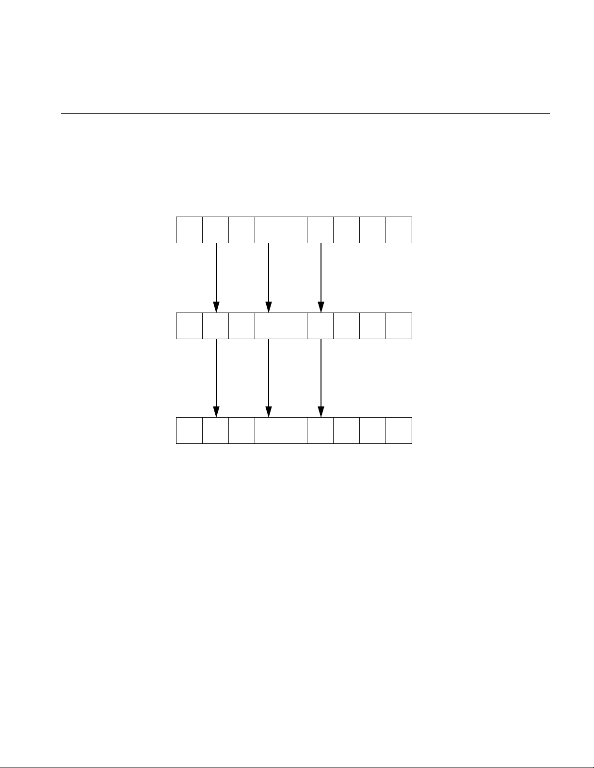
There are usually many transformation nodes in a scene graph and a shape is often
transformed more than once. Figure 1-2 illustrates how a leaf node is first transformed
twice, then placed in world space.
9
Page 36

Chapter 1: Getting Started with Cosmo 3D
Group node
Transform node
Group node
10
Transform node
Leaf node
Figure 1-2 Two Transformations into World Space
Page 37

Scene Graph Construction Classes
The csShape Class
csShape nodes, derived from csNode, define a textured geometry by associating a
csAppearance, which describes the look of a shape (such as its color), with a csGeometry,
which defines the dimensions of the geometry (such as whether the geometry is a cube
or sphere).
The csAppearance Class
A csAppearance contains fields to specify the material properties of a surface, including
transparency, color, and texture. csAppearance also provides some facilities borrowed
from OpenGL, like specifying whether the surface is drawn filled or in wireframe mode,
and the alpha and depth functions to use. csAppearance is associated with a csGeometry
container by a csShape, which contains fields for one appearance and a list of geometry.
The csGeometry Class
csGeometry encapsulates the geometric data to which a csAppearance can be applied.
For example, a csGeometry can define a sphere onto which the texture of an orange can
be applied to create a realistic image of an orange. Together, csGeometry and
csAppearance combine to form a textured shape. csShape associates the two classes.
11
Page 38

Chapter 1: Getting Started with Cosmo 3D
Classes That Determine How Things Are Drawn
The set of nodes discussed in this section determines how things are drawn.
•“csContext”—Maintains the OpenGL state, for example,
•“The csEnvironment Classes”—Determines how lights and fog are applied to its
children.
csContext
csContext defines the default, global graphics state of shapes in the scene graph. Shapes
inherit some or all of the csContext values according to the values set in a mask.
csAppearance values set on shapes override the default csContext values. Similarly,
geometry values, defined in csContext, can be overridden by individual shapes.
csContext is multi-threaded. A thread can associate a csContext and a csWindow to
facilitate multi-threaded processing. For more information about multi-threading, see
Chapter 13, “Multiprocessing.”
12
For more general information about csContext, see “csContext Overview” on page 35.
The csEnvironment Classes
The csEnvironment class determines how lights and fog are applied to the scene graph.
The lights that affect a csShape during a csDrawAction are the lights attached to all
ancestor csEnvironments of the shape, plus all lights applied before invoking the
traversal. For more information on lights, see Chapter 8, “Lighting and Fog.”
Page 39

Classes defining Geometric Objects
The actual geometric objects in a Cosmo 3D scene graph are derived as follows:
• As a direct subclass of csGeometry. These subclasses include csCone, csSphere, and
so on.
• A csGeoSet is a collection of primitives, such as points, lines, triangles, and triangle
strips, that, when arranged, create a geometry.
For more information, see Chapter 2, “Creating Geometries.”
Steps for Creating and Displaying a Simple Scene Graph
The following procedure summarizes the steps you take to create and render the simple
scene graph shown in Figure 1-1. This scene graph is created by the example program
discussed in Appendix B, “Cosmo 3D Sample Application.”
1. Create csAppearance and csGeometry containers to define the appearance and the
geometry of a shape.
Classes defining Geometric Objects
For more information on setting csAppearance values, see Chapter 3, “Specifying
the Appearance of Geometries.” For more information on setting csGeometry
values, see Chapter 2, “Creating Geometries.”
2. Create csShape and csTransform nodes.
For more information on setting csShape values, see Chapter 2, “Creating
Geometries.”
3. Associate the csAppearance and csGeometry containers using the csShape node.
4. Add the csShape node as a child of a csTransform node.
The csTransform node orients and positions the geometry encapsulated in the
csShape node. For more information on setting csTransform values, see Chapter 6,
“Placing Shapes in a Scene.”
Note: A csShape node by itself can be a complete scene graph. Typically, however,
scene graphs have many csShape nodes, most of which are connected to other parts
of the scene graph with csTransform nodes.
13
Page 40

Chapter 1: Getting Started with Cosmo 3D
5. Add the csTransform node as a child of a csGroup-type node.
For more information about adding nodes to scene graphs, see Chapter 6, “Placing
Shapes in a Scene.”
6. Create a window, csWindow, in which to view the application and interact with it.
7. Set the current graphical context, csContext.
8. Draw all of the shapes in world space by applying a csDrawAction to the root of the
scene graph.
The root node is the csGroup-type node at the “top” of the scene graph. For more
information about draw actions, see Chapter 7, “Traversing the Scene Graph.”
14
Page 41

Chapter 2
2. Creating Geometries
csGeometry is an abstract class. All derivations of the class represent one or more
geometric objects, either concrete (such as a sphere or cube) or abstract (such as geoSet).
The appearance of a shape—whether a sphere is dotted or striped— is characterized by
a csAppearance object, csContext object, or both. Combining a geometry with an
appearance completely describes the graphic content of a rendered object.
A csGeoSet is a collection of primitives, such as points, lines, triangles, and triangle
strips, that, when arranged, create a geometry. For example, a collection of points can
represent a star field and a collection of triangles can be arranged to form a sphere or a
landscape.
After a brief terminology overview, the first part of this chapter discusses the ready-made
geometries available in Cosmo 3D, such as csSphere and csCube. The remainder of the
chapter discusses how to create your own csGeoSet-derived classes and how to use the
csGeoSet-derived classes provided by Cosmo 3D.
These are the sections in this chapter:
•“Geometry Terminology” on page 16
•“Using Large Geometries” on page 16.
•“csGeoSet Attributes” on page 20.
•“Setting Attributes” on page 22.
•“Cosmo 3D-Derived csGeoSet Objects” on page 30.
15
Page 42

Chapter 2: Creating Geometries
Geometry Terminology
Table 2-1 briefly summarizes the geometry terminology used in this manual.
Understanding the key terms will help you understand the discussions of the different
elements.
Table 2-1 Geometry Terminology
Term Description Encapsulated in
Geometry An object of any form; the surface of
Appearance Contains all the parameters that specify
Shape Combination of a geometry and an
Context Maintains and manages the graphics
Using Large Geometries
Cosmo 3D provides five ready-made geometries:
• csSphere
• csCube
• csBox
• csCone
• csCylinder
which is uniform and non-descript.
the look of a geometry.
appearance.
state.
csGeometry objects or objects derived
from this class.
csAppearance object.
csShape object.
csContext object.
16
Page 43

Each class has methods that allow you to set and retrieve the values necessary to define
the geometry, including (where appropriate)
• coordinates of the center
• length of the radius
• height
• width
The names of the methods that set and retrieve these values are intuitively obvious, for
example, to set and retrieve the coordinates of the center of a geometry, you use methods
similar to the following:
void setCenter(const csVec3f& center);
void getCenter(csVec3f& center);
Creating csGeoSet Objects
csGeoSet is a virtual class from which all geometric primitives are derived. Each
csGeoSet-derived class contains a collection of primitives, such as points, quads, or
triangle strips. All of the primitives in a collection are of the same type. You can construct
a geometric object by specifying the coordinates of several of these primitives and
combine them in a collection. For example, you can arrange triangles to form a sphere or
a landscape. The vertices, normals, colors, and texture coordinates of each primitive are
captured as attributes of each primitive.
Creating csGeoSet Objects
Figure 2-1 illustrates how:
• Each csGeoSet-derived object contains an array of primitive shapes.
• Each primitive is made of an array of four attributes.
• Each of the four attributes refers to an array of attribute values, as shown in
Figure 2-1.
Note: The order of the attributes can be changed depending on the needs of the
application.
17
Page 44

Chapter 2: Creating Geometries
Figure 2-1 Primitives in a csGeoSet
csGeoSet
StripLengths
PrimCoords
ColorBind
MormalBind
TexCoordBind
CoordSet
ColorSet
NormalSet
TexCoordSet
CoordIndexSet
ColorIndexSet
NormalIndexSet
TextCoordIndexSet
le1
le2
le3
.
.
.
< x, y, z >
.
.
.
< r, g, b >
.
.
.
< nx, ny, nz >
.
.
.
< x, y, z >
.
.
.
18
These attributes are captured in csGeoSet fields.
Page 45

Creating csGeoSet Objects
csGeoSet Fields
The fields in a csGeoSet object can be grouped in the following manner:
Table 2-2 Fields in a csGeoSet
Field Default
General settings short cullFace
int primCount
Attribute specifications Color colors
Normal normals
TexCoord texCoords
Coord coords
Attribute index specifications Index colorIndices
Index normalIndices
Index texCoordIndices
Index coordIndices
Attribute binding specifications char colorBind
char normalBind
char texCoordBind
BACK
0
NULL
NULL
NULL
NULL
NULL
NULL
NULL
NULL
OFF
OFF
OFF
The remainder of this section describes csGeoSet general settings. The other parts of this
chapter describe the attribute fields.
For more information about cull facing, see “Face Culling” on page 152.
Setting the Number of Primitives
The following csGeoSet methods affect all of the primitives in a csGeoSet object:
void setPrimCount(csInt primCount);
csInt getPrimCount();
To specify or retrieve the number of primitives in a csGeoSet, use the setPrimCount()
and getPrimCount() methods. Appendix B, “Cosmo 3D Sample Application” shows
how to retrieve the number of primitives in a csGeoSet.
19
Page 46

Chapter 2: Creating Geometries
csGeoSet Attributes
csGeoSet is a virtual class from which all geometric primitives are derived. Cosmo
3D-supplied csGeoSet-derived classes include, for example:
• csPointSet—A collection of equally-sized points.
• csLineStripSet—A collection of linestrips, also known as polylines, of equal width.
• csTriStripSet—A collection of triangle strips.
• csPolySet—A collection of convex, coplanar polygons.
All of the primitives within a given set are equal in size. These primitives are defined by
an array of four attributes:
• color—(red, green, blue, alpha)
• normal—(Nx, Ny, Nz)
• texture coordinates—(S, T)
• coordinates—(X, Y, Z)
20
Each attribute consists of an array of two to four values; a primitive is defined by these
twelve values.
Note: Although texture coordinates can be specified using four values (S, T, R, Q), the R
value has no current meaning in Cosmo 3D because it does not support textures greater
than two dimensions, and the Q value is always one.
Attribute Bindings
Not all attributes can be applied with the same level of specificity. The levels of specificity
include
• The entire collection of primitives in a csGeoSet object.
• Individual primitives in a csGeoSet object.
• Individual vertices of individual primitives in a csGeoSet object.
Page 47

csGeoSet Attributes
For example, a single color can be specified for the entire collection of primitives, for
individual primitives, or per vertex. One set of coordinates, on the other hand, cannot be
specified for the entire collection of primitives, cannot be specified for individual
primitives, but must be specified per vertex. It does not make sense for all of the
primitives in a collection to have the same coordinates, nor does it make sense for all
vertices in each primitive to have the same coordinates. Each vertex must have its own
coordinates.
Each level of specificity is called a different binding, for example, an attribute that is
specified for an entire collection of primitives is said to have an OVERALL binding. A
binding tells you how many primitives in a csGeoSet object an attribute applies to.
Table 2-3 shows the different possible bindings.
Table 2-3 Attribute Bindings
OFF OVERALL PER_PRIMITIVE PER_VERTEX
colors yes yes yes yes
normals yes yes yes yes
texture coordinates yes no no yes
coordinates no no no yes
All attributes in a csGeoSet collection must share the same set of attribute bindings, for
example, you cannot specify colors-per-vertex for some primitives and
colors-per-primitive for others in the same csGeoSet object, the color binding must be the
same. You can, however, have, for example, color-per-vertex and overall normal
bindings in the same csGeoSet.
Setting Attribute Bindings
Three set...() methods in csGeoSet specify the attribute bindings for a csGeoSet object:
void setNormalBind(NormalBindEnum normalBind);
void setColorBind(ColorBindEnum colorBind);
void setTexCoordBind(TexCoordBindEnum texCoordBind);
There is a corresponding set of get...() methods that retrieve the attribute bindings for the
normals, colors, and texture coordinates, respectively.
21
Page 48

Chapter 2: Creating Geometries
The enumerated binding values that are valid for each of the attributes coincide with the
entries in Table 2-3.
enum NormalBindEnum
enum ColorBindEnum
};
enum TexCoordBindEnum
{
NO_NORMS,
OVERALL_NORMS,
PER_PRIM_NORMS,
PER_VERTEX_NORMS,
};
{
NO_COLORS,
OVERALL_COLORS,
PER_PRIM_COLORS,
PER_VERTEX_COLORS,
{
NO_TEX_COORDS,
PER_VERTEX_TEX_COORDS
}
Setting Attributes
22
To set the color of all the primitives in a csGeoSet object to the same value, for example,
use the OVERALL_COLORS binding in code similar to the following:
csTriangleStripSet* myTriangleStrip = new csTriangleStripSet();
myTriangleStrip->setColorBind(csGeoSet::OVERALL_COLORS);
Now that you know how to set attribute bindings, you need to know how to set the
attributes themselves.
As shown in Figure 2-1, csGeoSet objects store their primitives in an array. The array
contains:
• Three attribute values in the Normal array.
• Three (or four) attribute values in the Color array.
• Two attribute values in the Texture Coordinate array.
• Three attribute values in the Coordinate array.
Page 49

This pattern continues, as shown in Figure 2-2.
Array of
csGeoSet primitives
primitives
primitives
primitives
primitives
primitives
.
.
.
Figure 2-2 Sequential Specification of Attributes Per Primitive
Array of
attributes
attribute 1 color
attribute 1 normal
attribute 1 coord
attribute 1 tex coord
attribute 2 color
attribute 2 normal
attribute 2 coord
attribute 2 tex coord
.
.
.
Array of
color values
color value1
color value2
color value3
color value4
color value5
color value6
color value7
color value8
.
.
.
Setting Attributes
Array of
normal values
normal value1
normal value2
normal value3
normal value4
normal value5
normal value6
.
.
.
Indexing Attributes
Another option is to index the attribute values so that primitives can access any attribute
value and more than one primitive can use the same attribute value, as shown in
Figure 2-3.
23
Page 50

Chapter 2: Creating Geometries
csGeoSet
StripLengths
PrimCoords
ColorBind
MormalBind
TexCoordBind
CoordSet
ColorSet
NormalSet
TexCoordSet
CoordIndexSet
ColorIndexSet
NormalIndexSet
TextCoordIndexSet
le1
le2
le3
.
.
.
< x, y, z >
.
.
.
< r, g, b >
.
.
.
< nx, ny, nz >
.
.
.
< x, y, z >
.
.
.
24
i1
i2
i3
.
.
.
i1
i2
i3
.
.
.
i1
i2
i3
.
.
.
i1
i2
i3
.
.
.
Figure 2-3 Indexed Attributes
When to Index Attributes
For all primitives in a csGeoSet, you have to decide whether to use indexed or sequential
attributes; that is, all of the primitives within one csGeoSet must be referenced either
sequentially or by index. You cannot mix the two reference methods.
The governing principle for indexing attributes or not is how many vertices in a
geometry are shared. Consider the following two examples in Figure 2-4, where each dot
marks a vertex.
Page 51

Setting Attributes
024
135
Figure 2-4 Deciding Whether to Index Attributes
In the triangle strip, each vertex is shared by two adjoining triangles. In the square, the
same vertex is shared by eight triangles. Consider the task that is required to move these
vertices when, for example, morphing the object. If the vertices were not indexed, in the
square, the application would have to look up and alter eight triangles to change one
vertex.
In the case of the square, it is much more efficient to index the attributes. On the other
hand, if the attributes in the triangle strip were indexed, since each vertex is shared by
only two triangles, the index look-up time would exceed the time it would take to simply
update the vertices sequentially. In the case of the triangle strip, rendering is improved
by handling the attributes sequentially.
The deciding factor governing whether or not to index attributes relates to the number
of primitives that share the same attribute: if attributes are shared by many primitives,
the attributes should be indexed; if attributes are not shared by many primitives, the
attributes should be handled sequentially.
“Indexing Attributes” on page 28 describes the methods you use to index attributes.
25
Page 52

Chapter 2: Creating Geometries
Specifying Attributes
Whether you index your attributes or not, you must use the following set...() methods in
csGeoSet to specify the attributes in a specific csGeoSet object:
void setCoordsSet(csCoordSet* coords);
void setNormalsSet(csNormalSet* normals);
void setColorsSet(csColorSet* colors);
void setTexCoordsSet(csTexCoordSet* texCoords);
There is a corresponding set of get...() methods that retrieve the index settings for the
coordinates, normals, colors, and texture coordinates, respectively.
The set...() methods have the following arguments:
• coords is a three-dimensional array of coordinates representing the coordinates of
• normals is a three-dimensional array of normals for potentially every vertex in every
• colors is a four-dimensional array of colors for potentially every vertex in every
every vertex in every primitive in a csGeoSet object.
primitive in a csGeoSet object, depending on the binding.
primitive in a csGeoSet object, depending on the binding.
26
• texCoords is a two-dimensional array of coordinates representing the texture
coordinates of every vertex in every primitive in a csGeoSet object.
Using More Specific Attribute Arrays
Each of the four attributes has its own array. You must use one of the more
specifically-defined virtual array classes, as follows:
csCoordSet3f();
csNormalSet3f();
csColorSet3f();
csColorSet4f();
csTexCoordSet2f();
Each of these null constructors is overridden by a set of two constructors that are similar
in form to the following:
csCoordSet3f(int n);
csCoordSet3f(csData *array, short offset, short stride);
Page 53

Setting Attributes
The first constructor allows you to specify the number of array primitives, n.
The second constructor allows you to reference an array, *array, of attribute values,
specify the offset, offset, if any, and the stride, stride.
The stride mechanism that lets an application choose to keep all data staggered in a
single array (or use two arrays). For example, you could combine color, vertex, and
coordinate data and access each type as needed using the stride number. Stride specifies
the byte offset between pointers to consecutive vertexes, in effect, stride is a relative
offset, as shown in Figure 2-5.
CoordSet
(csData, offset, stride)
data
offset 0
stride 12
NormalSet
(csData, offset, stride)
data
offset 6
stride 12
csData
XYZ
RGB
Nx Ny Nz
Tx Ty
XYZ
RGB
Nx Ny Nz
Tx Ty
Figure 2-5 Stride and Offset Values
Set and Get Methods
Each of the virtual attribute-array classes, both the general and specific, have set and get
methods to set and return the values of the array. All set and get methods use the
following form:
void setCoordsSet(csCoordSet* coords);
csCoordSet* getCoordsSet();
27
Page 54

Chapter 2: Creating Geometries
Indexing Attributes
An indexed csGeoSet object uses a list of unsigned short integers to index an attribute
array. Four set...() methods in csGeoSet specify these indices:
void setCoordIndices(csIndexSet* coordIndices);
void setNormalIndices(csIndexSet* normalIndices);
void setColorIndices(csIndexSet* colorIndices);
void setTexCoordIndices(csIndexSet* texCoordIndices);
There is a corresponding set of get...() methods that retrieve the index settings for the
coordinates, normals, colors, and texture coordinates, respectively.
coordIndices is an array of coordinate indices. Each index points to a member in the
coordinate attribute array, as shown in Figure 2-3.
normalIndices is an array of normal indices. colorIndices is an array of color indices.
texCoordIndices is an array of texture coordinate indices.
Setting Attributes Example
28
Example 2-1 shows how to set attributes and their bindings.
Example 2-1 Setting Attributes
// Create a csGeoSet object
csTriStripSet *gset = new csTriStripSet;
// Allocate the attribute arrays
csCoordSet3f *vset = new csCoordSet3f(NumRings*RingVerts);
csNormalSet3f *nset = new csNormalSet3f(NumRings*RingVerts);
csIndexSet *iset = new csIndexSet((NumRings-1) *
2 * (RingVerts + 1));
csColorSet4f *cset = new csColorSet4f(NumRings-1);
csIndexSet *lengths = new csIndexSet(NumRings-1);
// Set the attributes
gset->setCoords(vset);
gset->setNormals(nset);
gset->setColors(cset);
// Set the attribute indices
gset->setCoordIndices(iset);
gset->setNormalIndices(iset);
gset->setPrimCount(NumRings-1);
Page 55

Setting Attributes
// Set the attribute bindings
gset->setNormalBind(csGeoSet::PER_VERTEX_NORMS);
gset->setColorBind(csGeoSet::PER_PRIM_COLORS);
// Prepare to fill the Attribute and Indices arrays
csVec3f *coords = vset->coords()->edit();
csVec3f *norms = nset->normals()->edit();
int *indices = iset->indices()->edit();
Editing Attribute Arrays
Cosmo 3D allows you to modify the values in arrays using the csNormalSet3f::edit() and
csNormalSet3f::editDone() methods. Although you can modify the values, you cannot
change the number of values in the array.
edit() returns a pointer to the attribute array. editDone() notifies any engines or sensors
connected to this field that the array has changed.
It is illegal to call any other editing methods between edit() and editDone().
Example 2-2 shows an example of editing attribute arrays.
Example 2-2 Editing Attribute Arrays
// cube normals
csNormalSet3f *nset = new csNormalSet3f(numCubeNorms);
nset->vector()->edit();
#if 0
for (i=0; i<numCubeNorms; i++)
nset->vector()->set(i,
csVec3f(cubeNorms[i][0], cubeNorms[i][1], cubeNorms[i][2]));
#else
nset->vector()->setRange(0, numCubeNorms, (csVec3f *)cubeNorms);
#endif
nset->vector()->editDone();
gset->setNormalSet(nset);
29
Page 56

Chapter 2: Creating Geometries
Cosmo 3D-Derived csGeoSet Objects
Cosmo 3D provides the following csGeoSet collections. Each is a derivative of
csGeoSet.
• csPointSet—A collection of equally-sized points.
• csLineSet—A collection of lines of equal length.
• csIndexedLineSet—A set of indexed line strips.
• csLineStripSet—A collection of linestrips, also known as polylines.
• csTriSet—A collection of triangles.
• csTriFanStrip—A collection of triangles that share a common vertex.
• csTriStripSet—A collection of triangle strips.
• csPolySet—A collection of convex, coplanar polygons.
• csQuadSet—A collection of quadrilaterals.
• csIndexedFaceSet—A polygon with faces that are indexed.
30
The following sections describe each of these primitive collections.
All of the classes contain virtual draw() and calcBound() methods. The draw() method
specifies how a csGeoSet object is drawn. The calcBound() method specifies how the
bounding box is computed. Other fields are specific to their geometries.
Using csPointSet
A csPointSet object contains a collection of equally-sized points. Point size is the
diameter of each point in pixels.
csPointSet contains the following fields:
void setSize(csFloat size);
csFloat getSize();
The setSize() and getSize() methods allow you to specify and find out, respectively, the
diameter, in pixels, of all the points in a csPointSet object.
Page 57

Cosmo 3D-Derived csGeoSet Objects
Using csLineSet
A csLineSet object contains a collection of lines of equal length. The fields allow you to
set and return the width of the lines used for drawing.
void setWidth(csFloat width);
csFloat getWidth();
Using csIndexedLineSet
A csIndexedLineSet object contains an indexed collection of lines of equal length. The
fields allow you to set and return the colors of the lines in the collection.
csMFInt* coordIndex() const;
csMFInt* colorIndex() const;
void setColorPerVertex(csBool colorPerVertex);
csBool getColorPerVertex();
Using csLineStripSet
A csLineStripSet object contains a collection of linestrips, otherwise known as polylines,
of equal width. Line width is specified in pixels.
csLineStripSet contains the following fields:
csMFInt* stripLength () const
void setWidth(csFloat width);
csFloat getWidth();
TheStripLength() method allows you to specify and find out, respectively, how many
line segments are in a csLineStripSet object.
The setWidth() and getWidth() methods allow you to specify and find out, respectively,
the width, in pixels, of each linestrip in a csLineStripSet object.
Using csTriSet
A csTriSet object contains a collection of triangles. This class serves as a class from which
csTriFanSet and csTriStripSet are derived.
31
Page 58

Chapter 2: Creating Geometries
Using csTriFanSet
A csTriFanSet is a set of triangles all of which share one common vertex, as shown in
Figure 2-6.
2
1
Figure 2-6 TriFanSet
3
4
5
0
You use the following method to retrieve or set the number of triangles in the
csTriFanSet.
csMFInt* fanLength() const;
Using csTriStripSet
A csTriStripSet object contains a collection of triangle strips. A triangle strip is a series of
adjacent triangles that form a strip, as shown in Figure 2-7.
13 5 79
32
02 4 68
Figure 2-7 Triangle Strip
Page 59

Cosmo 3D-Derived csGeoSet Objects
csTriStripSet contains the following field:
csMFInt* stripLength() const;
This field allows you to specify and find out how long each triangle strip is in a
csTriStripSet object. The length is expressed in the number of vertices per strip, for
example, three tristrips with individual lengths of 4, 6, and 8, would be represented by
an array of three integers:
csMFInt* length = [4, 6, 8];
Using csPolySet
A csPolySet object contains a collection of polygons. Polygons may have different
numbers of sides but must be convex and coplanar.
csPolySet contains the following methods:
csMFInt* polyLength () const;
This field allows you to specify and find out how many sides there are per polygon in a
csPolySet object.
Using csQuadSet
A csQuadSet object contains a collection of quadrilaterals.
Using csIndexedFaceSet
A csIndexedFaceSet object contains a collection of polyhedrons of equal size. The
member functions allow you to set and return the size of the polyhedrons in the
collection.
csMFInt* coordIndex() const;
csMFInt* colorIndex() const;
csMFInt* normalIndex() const;
csMFInt* texCoordIndex() const;
void setCCW(csBool ccw);
void setSolid(csBool solid);
void setConvex(csBool convex);
33
Page 60

Chapter 2: Creating Geometries
void setCreaseAngle(csFloat creaseAngle);
void setColorPerVertex(csBool colorPerVertex);
void setNormalPerVertex(csBool normalPerVertex);
There is a corresponding get...() method for every set...() statement.
The first four fields contain arrays for storing the color.
setCCW() is true if the vertices of these faces wind counter-clockwise when viewed from
the front.
setSolid() is true if this set of faces forms a closed volume (“solid”); in that case, faces on
the side of the solid facing away from the viewpoint don’t need to be drawn.
setConvex() is true if the faces in this set are convex. (Currently ignored.)
setCreaseAngle() sets the crease angle. If the angle between two faces is more than the
crease angle, the faces are assumed to be part of a single surface and are smooth shaded.
(Currently ignored.)
coordIndex() sets a VRML 2.0-style vertex coordinate index set.
34
colorIndex() sets a VRML 2.0-style color index set.
texCoordIndex() sets a VRML 2.0-style texture coordinate index set.
normalIndex() sets a VRML 2.0-style normal index set.
setColorPerVertex() is true if colors are assigned per vertex, otherwise per face.
setNormalPerVertex() is true if normals are assigned per vertex, otherwise per face.
Page 61

Chapter 3
3. Specifying the Appearance of Geometries
The geometry and appearance of a shape are independent of one another. The
appearance of a shape is the two-dimensional texture, such as the rind of an orange, that
is mapped onto a geometry.
This chapter describes how to specify the appearance of a geometry in the following
sections::
•“csContext Overview” on page 35.
•“Changing the Context” on page 39.
•“Using csAppearance” on page 40.
•“Applying Textures to Geometries” on page 42.
•“Material Settings” on page 51.
csContext Overview
•“Shade Model Settings” on page 53.
•“Transparency Settings” on page 53.
•“Making the Screen One Color” on page 39.
A csContext object maintains the OpenGL graphics state for a scene graph and therefore
contains all the default appearance values necessary to render a shape.
Appearance values, such as material and texture, can be specified per shape using
csAppearance. If csAppearance fields are not set, the shape inherits the default
appearance values set in csContext. For optimal performance, set as few csAppearance
object fields as possible by setting the global defaults in csContext to values that satisfy
the majority of geometries in a scene graph. This practice minimizes state changes while
rendering.
35
Page 62

Chapter 3: Specifying the Appearance of Geometries
There is an inheritance mask in each csAppearance that specifies which appearance
values are inherited by csAppearance from csContext. csAppearance values
automatically override csContext default values on a per-shape basis, regardless of the
bit values in the inheritance mask.
State Machine
csContext maintains and manages OpenGL graphics state for the purpose of efficient
graphics pipeline state control. OpenGL is a state machine: you put it into various states
(or modes) that then remain in effect until you change them. For example, the current
color is a state variable. The Cosmo 3D context maintains two notions of state:
• Default state—is the global graphics state defined on a per-context basis and
maintained separately from the current state.
• Current state—represents the accumulation of the default state and the state set
when csAppearance nodes are encountered during a traversal.
State that is not explicitly set in a csAppearance via the appropriate csAppearance set()
methods is inherited from the default state. An inheritance mask, however, specifies
which csContext fields a shape inherits by default.
36
The effect of a set() method is immediate, as if you made the OpenGL calls directly. The
set() methods affect the current state but have no effect on the default state.
Inheritance Mask
Inheritance masks specify which csContext fields are inherited by csAppearance. Each
bit in the bitmask corresponds to a specific csAppearance field. All fields are inherited by
default.
Figure 3-1 demonstrates how the inheritance mask works as a result of the code in
Example 3-1.
Example 3-1 Inheritance Mask
csContext *ctx = new cscontext;
ctx->setCullFace(BACK);
ctx->setLightEnable(TRUE);
.
Page 63
.
.
csAppearance *app = new csAppearance;
app->setMaterial(mtl);
shape->setAppearance(app);
1
1
csContext Overview
csContext elements
(Default state)000 000 0
000 00000
Light enable
000111
1
Material
CullFace
0
csAppearance fields
csContext elements
(Current state)
00
Figure 3-1 Inheritance Mask
All 0 bits indicate that the default value is used.
When you set a csAppearance value, its corresponding bit in the inheritance mask is set.
Accessing States
Applications can access the current state using the various get() methods. The primary
use of the get() method is to ask the system about its current state. Cosmo 3D makes this
state available so that a user callback can know the current state of the system and make
OpenGL calls appropriately.
37
Page 64

Chapter 3: Specifying the Appearance of Geometries
Warning: It is critical that such a callback not alter the OpenGL state.
You can avoid altering the OpenGL state either by using csContext::set() calls or by
saving and restoring OpenGL state explicitly upon entry and exit of the callback.
What Modifies the Graphics State?
As a csDrawAction traverses the scene graph, the current state is modified when:
• Appearances a their draw methods are invoked.
• Calls users make to various set() methods in csContext invoke pre- and post-node
callbacks.
Traversal Order
The actual appearance of a csGeometry being drawn is independent of traversal order.
Only that csShape’s appearance and the default state affect the actual appearance. At no
time does Cosmo 3D depend on the traversal order of the draw action. No guarantees are
made about traversal order because the traversal order of the draw is subject to change.
Because applications cannot depend on draw traversal order to imply the state of the
context, methods to query the context for its current state are available.
38
csContext in Multi-threaded Programs
csContext can be used in a multi-threaded program. When makeCurrent() is called
within a given thread, that context is attached to the thread. Binding a thread to a context
allows multi-pipe or multi-window rendering in parallel using a single, shared copy of
the scene graph.
For more information about multi-threaded implementation, see Chapter 13,
“Multiprocessing.”
Page 65

Changing the Context
Overriding Appearances and Geometry Properties with csContext
In general, csAppearance settings override csContext default values. You can, however,
override csAppearance settings using csContext::pushOverrideAppearance(). Only one
override appearance per context can be in place at a time.
You can override some properties that are not in csAppearance and are
geometry-specific through the use of pushOverrideGeoProp(). Currently, csCullFace,
csLineWidth, and csPointSize are the only geometry-specific properties that can be
overridden.
Making the Screen One Color
To change the screen to a specified color, use one of the following csContext methods:
static void clear(int which);
static void clear(int which, float r, float g, float b, float a);
where which is a bitmask specifying whether to clear the color planes, depth planes, or
both.
Changing the Context
The first clear() method clears the screen to black. The second version allows you to set
a uniform color and transparency.
You can create multiple csContext objects but only one can be active at a time. In this way,
in addition to changing field values in a context object, you can change the entire context
all at once using makeCurrent(). This method replaces the current context with the
csContext object specified in the argument, for example:
csContext* context1 = new csContext;
csContext* context2 = new csContext;
context1->makeCurrent(display, window);
context2->makeCurrent(display, window);
39
Page 66

Chapter 3: Specifying the Appearance of Geometries
In this example, the second context replaces the first.
• display is a pointer to the X window display.
• window is the GLXDrawable in which the scene is displayed.
getCurrent() returns the context object on top of the context stack.
csWindow has a context and calls makeCurrent() automatically.
Using csAppearance
csAppearance fields define the appearance of a csGeometry object, for example, its
texture, material, or color. All of the fields in csAppearance are replicated in csContext.
Inheriting Appearance Values
To specify the appearance of a csGeometry, you can either
• Set all of the appearance fields in a csAppearance object.
40
• Use the inherited, global, default values from the current context, csContext.
• Use a combination of the first two options.
If you set all of the fields of an appearance object, the appearance object becomes the full
graphic context of the csShape. The more appearance fields you set, however, the slower
the application’s performance because you are triggering lots of state changes.
For maximum performance, set the appearance values in csContext to satisfy the
maximum number of shapes so that the fewest number of csAppearance fields are set on
a per-shape basis.
Setting Appearance Fields Locally
The only fields that you should set locally are those that change often, such as the field
values for material and texture. Changing a field value locally overrides any value
inherited from csContext.
Page 67

Using csAppearance
The csAppearance class includes a series of set...() methods to define the appearance
characteristics of a geometry. A series of corresponding get...() methods provide access
to those values. The following set...() methods are described in greater detail in the rest
of this chapter:
void setTexture(csTexture* texture);
void setTexEnable(csBool texEnable);
void setTexMode(csContext::TexModeEnum texMode);
void setTexBlendColor(const csVec4f& texBlendColor);
void setTexBlendColor(csFloat v0, csFloat v1, csFloat v2, csFloat v3);
void setTexEnv(csContext::TexEnvEnum texEnv);
void setTexGen(csTexGen* texGen);
void setTexGenEnable(csBool texGenEnable);
void setMaterial(csMaterial* material);
void setLightEnable(csBool lightEnable);
void setShadeModel(csContext::ShadeModelEnum shadeModel);
void setTranspEnable(csBool transpEnable);
void setTranspMode(csContext::TranspModeEnum transpMode);
void setAlphaFunc(csContext::AlphaFuncEnum alphaFunc);
void setAlphaRef(csFloat alphaRef);
void setBlendColor(const csVec4f& blendColor);
void setBlendColor(csFloat v0, csFloat v1, csFloat v2, csFloat v3);
void setSrcBlendFunc(csContext::SrcBlendFuncEnum srcBlendFunc);
void setDstBlendFunc(csContext::DstBlendFuncEnum dstBlendFunc);
void setColorMask(const csVec4ub &colorMask);
void setColorMask(csUByte v0, csUByte v1, csUByte v2, csUByte v3);
void setDepthFunc(csContext::DepthFuncEnum depthFunc);
void setDepthMask(csUInt depthMask);
void setFogEnable(csBool fogEnable);
void setPolyMode(csContext::PolyModeEnum polyMode);
These method are separated into two groups:
• Methods containing the string “tex” modify textures.
• The remaining methods modify the appearance of geometries.
Lazy Updating of Appearance Values
csAppearance values are updated in a lazy way: a value is changed only when it is used.
For example, if a ball is currently displayed and you change its color using setColor(),
the ball would change color immediately on the screen. If, however, the ball is out of view
of the camera, the color of the ball would not be updated until it is seen by the camera.
41
Page 68

Chapter 3: Specifying the Appearance of Geometries
Applying Textures to Geometries
One way to affect the appearance of a geometry is to apply a texture to it. A texture is a
rectangular 2D image, for example, a 2D map of the world. This rectangular texture is
scaled or repeated to fit on the surface of a 3D object, such as a sphere. The clamping and
repetition of a texture over a surface is programmatically controllable.
To create the image of an orange, for example, you first create the orange, pitted texture
of orange rind and then apply it to a sphere. The difference between using and not using
a texture, in this example, is the difference between rendering a generic sphere and a
realistic-looking orange.
42
Figure 3-2 Applying a Texture to a Geometry
Texture Map Coordinates
A texture map is always defined by the coordinates s, for the horizontal component, and
t, for the vertical component, each of which range in values from 0.0 to 1.0, as shown in
Figure 3-3.
Page 69

1.0
Applying Textures to Geometries
t
0.0 1.0
Figure 3-3 Texture Coordinates
s
Texture coordinates are assigned to each vertex of a geometry either by you or by Cosmo
3D.
Applying a Texture
To apply a texture to a geometry, set the argument of the csAppearance::setTexEnable()
method to ON. If you do not want to apply a texture to a geometry, set the argument of
setTexEnable() to OFF.
Texture rendering uses the texture values specified in csContext by default. To set the
texture values locally, however, use the following methods in csAppearance:
setTexture() to specify the image used as the texture.
setTexMode() to specify the speed and quality of the rendered texture.
setTexBlendColor()
to specify the color to use in “blend” mode.
setTexEnv() to specify how texture colors are blended with the colors of a geometry.
setTexGen(), setTexGenEnable()
to generate, if enabled, texture coordinates automatically instead of
using the csGeoSet’s TexCoordSet.
The following sections describe these methods.
43
Page 70

Chapter 3: Specifying the Appearance of Geometries
Specifying a Texture Image
To apply a texture to a geometry, supply a csTexture object in the argument of
setTexture(). csTexture is a class consisting of the following fields and default values:
csSFString filename “noName”
csMFRef imageLevel[]
csSFEnum format 0
csSFEnum repeat_S REPEAT
csSFEnum repeat_T REPEAT
csSFEnum minFilter FAST
csSFEnum magFilter FAST
csSFEnum source 0
imageLevel is an array of MIPmap levels for this texture of type csImages. If this field is
not set or has all NULL values, the texture is loaded from csSFString fileName instead.
format is the pixel format of the image. For more information about pixel format, see
“Color Components” on page 47.
repeat_S and repeat_T specify whether or not the texture is repeated in the s and t
directions on the geometry, respectively. If the texture is not repeated, it is clamped.
44
minFilter specifies what to do with texels that project smaller than a screen pixel.
Possible values include NEAREST_MIN, LINEAR_MIN, or MIPMAP.
magFilter specifies what to do with texels that project larger than a screen pixel. Possible
values include NEAREST_MAX or LINEAR_MAX.
Texture Mode Settings
The texture mode method allows you to specify texture rendering speed, quality, and
perspective where speed and quality, and speed and perspective are trade-offs.
You specify the mode of the texture rendering using setTexMode() with one of the
following arguments from csContext::TexModeEnum:
FAST_TEX for a low quality, more quickly-rendered texture.
NICE_TEX for a high quality, more slowly-rendered texture.
NON_PERSP_TEX
for a non-perspectively-correct, more quickly-rendered texture.
PERSP_TEX for a more slowly-rendered texture in perspective.
Page 71

Applying Textures to Geometries
When you choose the NON_PERSP_TEX mode, Cosmo 3D applies the texture to a
geometry without proper perspective. For example, if you apply a texture to a plane
extending into the Z dimension, the pattern should not distort but just appear to recede
into the distance. In NON_PERSP_TEX mode, however, the pattern is distorted, as
shown in Figure 3-4.
Non Perspective Perspective
Figure 3-4 Non-Perspective and Perspective Modes
If you enable texture rendering but do not set the texture mode in a csContext or
csAppearance object, the texture rendering mode is defined by the csTexture object in the
argument of csAppearance::setTexture() or csContext::setTexture(). A csTexture object
can specify one of the values in TexModeEnum.
45
Page 72

Chapter 3: Specifying the Appearance of Geometries
Texture Environment Settings
Texture environment variables specify how texture colors are blended with the colors of
a geometry; the texture color can replace, blend with, or subtract from the colors already
on the geometry.
To specify how texture colors are blended with the colors of a geometry, use the
setTexEnv() method with one of the following csContext::TexEnvEnum values as an
argument:
MODULATE_TENV
multiplies the shaded color of the geometry by the texture color. If the
texture has an alpha component, the alpha value modulates the
geometry’s transparency, for example, if a black and white texture, such
as text, is applied to a green polygon, the polygon remains green and the
writing appears as dark green lettering. MODULATE is the default
value.
BLEND_TENV
uses the texture color to blend together the blend color and the
underlying geometry’s color. In the above example, the lettering would
be a mixture of green, white, and black.
46
REPLACE_TENV
replaces the underlying geometry’s color with the texture color. If the
texture has an alpha component, the alpha value specifies the texture’s
transparency, allowing the geometry’s color to show through the
texture. In the above example, the lettering would be white and black.
ADD_TENV adds the underlying geometry’s color with the texture color.
DECAL_TENV replaces the underlying geometry’s color with the color of the texture.
When this token is used with RGBA values, the alpha value determines
the blending between the shape’s and texture’s color: when the alpha
value is 1.0, the color is only the texture’s; when the value is 0.0, the color
is only that of the shape’s.
Tip: If you use MODULATE, consider surrounding your texture images with a one-pixel
border of white pixels and set csTexture::setRepeatS() and csTexture::setRepeatT() to
CLAMP so the geometry’s color is used where the texture runs out.
Page 73

Applying Textures to Geometries
Color Components
A texture image can have up to four components per texture element:
• A one-component image consists of a luminance value, Lt. One-component textures
are often referred to as intensity maps. For example, an image of a statue could use
polygons of different intensities to shade and provide detail.
• A two-component image consists of luminance, Lt, and transparency, At. For example,
you could create an architect’s diagram of a house using polygons of different
intensities to give detail to the building materials and then vary the transparency of
the polygons to see through the building materials.
• A three-component image consists of a set of RGB values, referred to as a color triplet,
C
. For example, any color image is at least a three-component image.
t
• A four-component image consists of an RGB (or Ct) set of values, and transparency, At.
The “t” subscript denotes the transparency or the color of the texture. For example,
you could create an architect’s diagram of a house using a variety of colors and
transparencies.
The color components work with the texture environments in the following way:
• MODULATE works with any texture file.
• BLEND works with one- to four-component textures.
• REPLACE works with three- or four-component textures.
• ADD works with three- or four-component textures.
• DECAL works with three- or four-component textures.
Tip: MODULATE works best with bright materials because the texture intensity is
reduced by the factor of the geometry’s intensity.
47
Page 74

Chapter 3: Specifying the Appearance of Geometries
Specifying Texture Coordinates
There are two ways to specify how a texture is applied to a geometry:
• Use the default. Cosmo 3D applies textures to geometries according to the
geometry.
• Use the texture coordinate function, setTexGen().
Using the Default
Cosmo 3D applies textures to geometries according to the geometry. For all geometries
subclassed from csGeometry, Cosmo 3D
• Computes the bounding box.
• Turns the texture so its longest side is in the horizontal (s) direction.
The horizontal (s) value ranges from 0.0 to 1.0 and the vertical component ranges from
0.0 to n, where n equals the ratio of the t dimension to the s dimension; this ratio
maintains the texture without distorting it.
48
Using the Texture Coordinate Function
The setTexGen() method generates texture coordinates by, in effect, projecting a texture
plane onto a geometry, as shown in Figure 3-5.
Figure 3-5 Texture Coordinate Function
Page 75

Applying Textures to Geometries
The setTexGen() method specifies
• Whether or not the texture plane is repeated across the geometry.
• Whether the texture plane is stationary or moves in concert with the motion of the
geometry.
The setTexGen() method takes a csTexGen object for an argument. In a csTexGen object,
you set the
• Repetition of the texture image in three dimensions, s, t, and r.
• Mode of the texture in each of the dimensions.
For example, csTexGen::setPlaneS(2.5, 0, 0, 0) repeats the texture two-and-a-half
times in the s dimension.
Figure 3-6 shows how a texture plane is repeated across a geometry.
Figure 3-6 Repeated Texture on a Geometry
The default values of both s plane equations are (1,0,0,0), both t plane equations are
(0,1,0,0), and all r and q plane equations are (0,0,0,0).
49
Page 76

Chapter 3: Specifying the Appearance of Geometries
Setting the csTexGen Mode
If you think of the texture plane as being projected onto the surface of a geometry rather
than being on the surface of a geometry, it is easy to understand how the mode settings
in csTexGen work. Either the plane is stationary and the geometry moves “under” it or
the plane moves in concert with the geometry. In the second case, the colors of the plane
appear to be part of the geometry when it moves; in the first case, the colors of the plane
appear to ride over the geometry when it moves.
You set the mode of each plane in csTexGen to one of the following values:
OFF Turns off the texture.
EYE_LINEAR Lets the geometry turn independently of the texture plane. In this case,
the colors of the plane appear to ride over the geometry when it moves.
This value is the default.
OBJECT_LINEAR
Lets the texture move in coordination with the geometry. In this case, the
texture appears to be on the surface of the geometry.
SPHERE_MAP
Lets the texture pattern remain stationary as the geometry moves thus
producing a mirror-like, circular reflection.
50
EYE_LINEAR_IDENT
Loads the identity matrix onto the modelview stack before loading the
plane equation.
Enabling Texture Generation
The setTexGen() function is enabled or disabled using setTexGenEnable() with an
argument of ON or OFF, respectively. Enabling the generation is, in effect, like turning on
the light which shines through the plane and onto a geometry. Disabling the generation
turns off the light.
The remaining sections apply to the appearance of the geometry itself.
Page 77

Material Settings
Material Settings
The material field in csAppearance defines the surface qualities of a geometry, such as
how well it reflects light, what color it reflects, and what color it emits. The material field
is of type csMaterial, which has the following set...() methods:
void setAmbientIntensity(csFloat ambientintensity);
void setAmbientColor (const csVec3f& ambientColor);
void setDiffuseColor(const csVec3f& diffuseColor);
void setDiffuseColor(float v0, float v1, float v2);
void setSpecularColor(const csVec3f& specularColor);
void setSpecularColor(float v0, float v1, float v2);
void setEmissiveColor(const csVec3f& emissiveColor);
void setEmissiveColor(float v0, float v1, float v2);
void setAmbientIndex(csShort ambientIndex);
void setDiffuseIndex(csShort diffuseIndex);
void setSpecularIndex(csShort specularIndex);
void setShininess(csFloat shininess);
void setTransparency(csFloat transparency);
csMaterial also has a corresponding set of get...() methods.
Ambient color is the color of the light reflected from an object when lit by another ambient
object in the scene. The default value is [0.2, 0.2, 0.2]. Ambient intensity refers to the
strength of the reflection—a value between 0.0 and 1.0 where 1.0 is a strong reflection.
Ambient index refers to a color lookup table in which each ambient color is paired with
an index number for easy look-ups.
Diffuse color is an object’s base color. The default value is [0.8, 0.8, 0.8]. Diffuse index
refers to a color lookup table in which each diffuse color is paired with an index number
for easy look-ups.
Specular color is the reflected color of an object’s highlights. Specular intensity refers to
the strength of the reflection. The default value is [0.0, 0.0, 0.0]. Specular index refers to a
color lookup table in which each specular color is paired with an index number for easy
look ups.
Emissive color is the color emitted by an object. A lamp shade for example, might have a
base color of yellow. When the lamp is turned on, however, the emissive color might be
white. The default value is [0.0, 0.0, 0.0].
51
Page 78

Chapter 3: Specifying the Appearance of Geometries
Shininess describes how much of the surroundings are reflected by an object, for example,
a mirror would have a large shininess value so that surrounding objects would be seen
in it. Values range from 0.0, for a very dull surface, to 1.0, for a highly polished surface.
The default value is 0.2.
Transparency describes how opaque or clear an object is, for example, water might be
more clear than opaque. Values range from 0.0, for opaque, to 1.0, for complete
transparency. The default value is 0.0.
Material Example
The following example shows the material settings for gold:
csMaterial *gold = new csMaterial;
gold->setAmbientColor(.3, .1, .1);
gold->setDiffuseColor(.8, .7, .2);
gold->setSpecularColor(.4, .3, .1);
gold->setShininess(.4);
Since gold is opaque, the default value, 0.0, for transparency suffices.
52
Filling Geometries
The setPolyMode() method specifies how to render the elementary polygons that
compose a geometry. The following values for the method are valid:
POINT_PMODE
The polygon is rendered as points.
LINE_PMODE
The polygon is rendered as a line. This option is equivalent to rendering
the geometry as a wireframe.
FILL_PMODE
The polygon is rendered as filled.
For example, if you use POINT_PMODE, a triangle would appear as three points.
LINE_PMODE would render a triangle as a set of three lines; FILL_PMODE would
render the triangle as filled.
Page 79

Shade Model Settings
You set the shading model using the setShadeModel() method with one of the following
csContext::ShadeModelEnum values as its argument:
FLAT_SHADE Each primitive, geometric polygon that comprises a geometry has the
SMOOTH_SHADE
Transparency Settings
To specify the transparency of a geometry locally, enable the transparency mode by
setting setTranspEnable() to ON and then specifying the transparency mode in the
argument of setTranspMode(). The possible transparency values include
FAST_TRANSP Produces as quickly-rendered, lower-quality transparent geometry.
Shade Model Settings
same shade value. This option has the effect of making the primitive
geometric polygons visible.
Shade values are interpolated across primitive geometric polygons. This
option makes the primitive polygons look more like a curved surface.
NICE_TRANSP Produces a more slowly-rendered, higher-quality transparent geometry.
BLEND_TRANSP
Produces a smooth transparency between foreground and background
images.
SCREEN_DOOR_TRANSP
Produces a mottled transparency, as though every other pixel is
transparent.
Commonly, you use the setTranspMode() twice: you specify
• FAST_TRANSP or NICE_TRANSP
• BLEND_TRANSP or SCREEN_DOOR_TRANSP
Producing Transparency Without Blending
The setAlphaFunc() method sets the requirements for whether or not a pixel is rendered.
Not rendering some of the pixels in a geometry has the effect of making the geometry
partially transparent.
53
Page 80

Chapter 3: Specifying the Appearance of Geometries
To use the setAlphaFunc() method, you first set the reference value against which you
measure the alpha value of the pixel to be drawn using setAlphaRef(), for example
setAlphaRef(10);
Then you supply, as an argument to setAlphaFunc(), one of the values of
csContext::AlphaFuncEnum:
• NEVER_AFUNC
• LESS_AFUNC
• EQUAL_AFUNC
• LEQUAL_AFUNC
• GREATER_AFUNC
• NOTEQUAL_AFUNC
• GEQUAL_AFUNC
• ALWAYS_AFUNC
For example, the following code
setAlphaRef(0.5);
setAlphaFunc(LESS_AFUNC);
54
is similar to the following lines of code:
if(Alpha < 0.5) {
//draw the pixel };
where Alpha is the alpha values of pixels to be drawn in a geometry.
The values have the following effects:
NEVER_AFUNC
The incoming pixel is never rendered. This function has the effect of
creating a totally transparent geometry.
LESS_AFUNC The incoming pixel is rendered only if its alpha value is less than the
reference value.
ALWAYS_AFUNC
The incoming pixel is always displayed. This function has the effect of
creating an opaque geometry.
Page 81

Chapter 4
4. Scene Graph Nodes
A node is an object that can be part of or entirely comprise a scene graph. Typically, a node
is a collection of one or more fields and methods that together perform a specific
function, for example, a csShape node encapsulates all information about the shape and
appearance of a geometry.
Cosmo 3D nodes are divided into two types:
• group—associate other nodes.
• leaf— contain rendering information.
This chapter describes nodes and node types.
These are the sections in this chapter:
•“What Is a Node” on page 56.
•“Group Nodes” on page 58.
•“Leaf Nodes” on page 57.
•“Setting the Values in Scene Graph Nodes” on page 61.
55
Page 82

Chapter 4: Scene Graph Nodes
What Is a Node
A node is a collection of one or more fields and methods. Each field is a C++ class with
data members and methods that get and set those member values. The fields set a variety
of parameters. For example, some of the fields in the csGeoSet are summarized in
Table 4-1.
Table 4-1 Examples of Fields in Nodes
Field
Type
SFRef COORDS Is a csCoordSet containing vertex coordinates.
SFRef NORMALS Is a csNormalSet containing normals for a geometry.
SFRef COLORS Is a csColorSet containing colors for a geometry.
SFRef TEX_COORDS Is a csTexCoord containing texture coordinates for a
SFRef COORD_INDICES Is a csIndexSet providing indices into a csCoordSet.
SFRef NORMAL_INDICES Is a csIndexSet providing indices into a csNormalSet.
SFRef COLOR_INDICES Is a csIndexSet providing indices into a csColorSet.
SFRef TEX_COORD_INDICES Is a csIndexSet providing indices into a csTexCoordSet.
SFEnum CULL_FACE Specifies whether to cull back-facing polygons,
Fields Description
geometry.
front-facing polygons, or no polygons.
Each node supplies default values for each of its fields.
Node Types
56
There are two types of nodes:
• Group—associates nodes into hierarchies.
• Leaf—sets the visual and audio values for a scene.
The following sections describe these node types.
Page 83

Leaf Nodes
Leaf Nodes
Leaf nodes are responsible for defining the visual and aural elements portrayed in a
scene. Leaf nodes cannot have child nodes.
The following list shows all of the different types of Cosmo 3D leaf nodes; all are
derivatives of csLeaf.
• csShape—associates a csGeometry object with a csAppearance object.
• csLight—is an abstract base class for light sources.
• csDirectionalLight—is a directional light source whose origin is at infinity.
• csPointLight—is a point source of light that radiates equally in all directions.
• csSpotLight—is a conical spot light.
The following section describes csShape. All of the other nodes are described in
Chapter 8, “Lighting and Fog.”
csShape
A csShape node associates a csGeometry object with a csAppearance object. Together,
the csGeometry and csAppearance objects create a complete description of a shape.
To associate a csGeometry object with a csAppearance object, use the following
methods:
void setAppearance(csAppearance* appearance);
void setGeometry(csGeometry* geometry);
There is a corresponding set of get...() methods that return the current appearance and
geometry objects in the csShape object.
57
Page 84

Chapter 4: Scene Graph Nodes
Group Nodes
Group nodes associate other nodes into a hierarchy known as a scene graph. Only group
nodes can have children. A group node, for example, might associate two csShape
nodes, as shown in Figure 4-1.
Group
node
csShape
node
csShape
node
58
Figure 4-1 A Simple Grouping
Actions, such as a draw action, applied to a group node may be applied in no particular
order to some or all of its children. A group node, then, defines the scope of an action.
For more information about actions, see Chapter 7, “Traversing the Scene Graph.”
Group Node Types
The following list shows all of the different types of Cosmo 3D group nodes; all are
derivatives of csGroup:
• csSwitch—selects none, one, or all of its children, depending on its value. See
“Using csSwitch to Switch Between Nodes” on page 59.
• csBillboard—rotates its children to face the viewer at the same time. See “Using
csBillboard” on page 60.
Page 85

Group Nodes
• csLOD—(level-of-detail) is a switch that selects one of its children based on the
distance between the camera and the shape encapsulated by the csLOD; the closer
the shape, the greater the detail used when rendering the shape, the farther away
the shape, the less detailed the shape. For more information, see Chapter 14,
“Optimizing Rendering.”
• csTransform—positions and orients a shape in the coordinate system of the parent
node to csTransform. For more information, see Chapter 6, “Placing Shapes in a
Scene.”
• csEnvironment—is a grouping node which defines the scope of influence for the
effects provided by csLight. For more information, see Chapter 8, “Lighting and
Fog.”
Using csSwitch to Switch Between Nodes
The csSwitch node selects none, one, or all of its children. The constructor has the
following prototype:
csSwitch();
To specify whether none, one, or all of a csSwitch node’s children are selected, use the
following member function:
void setWhichChild(int which);
The possible values of which are
• NO_CHILDREN—to select no nodes
• an integer—to specify a child node
• ALL_CHILDREN—to select all of the children of the csSwitch node
Each child of a switch node is assigned an index number when added to the group node:
the first child added is index 0, the second child added is index 1, and so on.
You might use a csSwitch node to create an animation sequence. For example, if each of
the five child nodes of a csSwitch node contained the image of a character in different
stages of walking, your application could switch sequentially between the child nodes to
create a simple animation sequence.
59
Page 86

Chapter 4: Scene Graph Nodes
Using csBillboard
csBillboard is a subclass of csGroup. It is used to rotate its children to face the viewer at
all times. csBillboard has the following fields:
csMFRef children (inherited from csGroup)
csEnum mode
csMFVec3f position
csVec3f axis
The mode field specifies one of three billboard modes: AXIAL, POINT_SCREEN, and
POINT_OBJECT. The mode defines how the billboard’s children should be rotated to
face the viewer. Specific descriptions of each mode follow:
• AXIAL: In this mode, the local +z axis is rotated about the billboard axis to face the
viewer (i.e. to match the negation of the view vector).
• POINT_SCREEN: In this mode, the local +z axis is rotated to face the viewer. The
local +y axis is aligned with the screen’s +y axis.
• POINT_OBJECT: In this mode, the local +z axis is rotated to face the viewer. The
remaining degree of freedom is used to minimize the angle between the local +y
axis and the billboard axis.
60
The position field specifies a position to which each child should be translated after it has
been rotated to face the viewer. There should be as many entries in the position field as
there are children.
The axis field is used in AXIAL and POINT_OBJECT modes.
Page 87

Setting the Values in Scene Graph Nodes
Cosmo 3D allows you to set the values for nodes in two ways: either using the set()
method in each of the node’s fields, or by using tokens.
Setting the fields is different depending on whether or not the variable has a single or
multiple value. If the variable has a single value, the variable can be set directly; if it has
multiple values, the particular value in the set of values must be specified, as shown in
Figure 4-2.
Single value field Multiple value field
Figure 4-2 Setting Single and Multiple-Value Variables
Setting the Values in Scene Graph Nodes
Must specify
one of these
values to set
Using set() and get() Methods to Set and Get Single-Value Fields
Nodes are composed of one or more fields, each of which is a class containing set(), get(),
and, optionally, other methods. The csAppearance node, for example, contains many
fields, some of which are Shininess, Material, and TranspEnable (enable transparency).
To define one of these fields, you use the appropriate set() method, such as
csMaterial *mtl->setShininess(ShininessValue);
ShininessValue = mtl->getShininess();
color = mtl->getDiffuseColor();
ShininessValue is a float. The first line of code sets the shininess value of the csMaterial,
mtl. The following lines return an atomic, single value, ShininessValue, and a composite,
single value, color. A composite, single value is a set of numbers that represent a single
feature, for example, RGB values represent one feature: color
61
Page 88

Chapter 4: Scene Graph Nodes
Using Tokens to Set and Get Single-Value Fields
To use tokens to set or get single-value fields, you
1. Get a handle to the field specified by the token.
2. Use the handle to set or get the field.
For example:
F = mtl->getField(SHININESS);
F->set(ShininessValue);
ShininessValue = F->get();
F->get(c);
ShininessValue is a float. The first line of code returns a handle, F, to the shininess field.
The second line then sets the value of that field.
The third line returns an atomic, single value. Since there is only one value, it does not
need to be specified in the argument. The last line returns a composite, single value, F.
62
Using set() and get() Methods to Set and Get Multiple-Value Fields
Multiple-value fields are arrays of variables. For example, the csMaterial field has a
number of values, including
sfFloat Shininess;
sfVec DiffuseColor;
To get or set a value in a csMaterial field, you must specify which of the values in the
field you are retrieving or setting, for example:
csGroup *g;
g->addChild(child);
child = g->getChild(1);
Child nodes of a group node are numbered, starting with zero. To retrieve the specific
child in the csGroup, you must specify in the argument of getChild() which child you
want returned; in this example, it is child number one.
Page 89

Setting the Values in Scene Graph Nodes
Using Tokens to Set and Get Multiple-Value Fields
To use tokens to set or get multiple-value fields, you
1. Get a handle to the field specified by the token.
2. Use the handle to set or get values from a specific variable in the field.
For example:
csMFRef *F;
csGroup *g;
F = g->getField(CHILDREN);
F->append(child);
child = F->get(1);
To retrieve the specific child in the csGroup, the last line of code shows that you must
specify in the argument of get() which child you want returned; in this example, it is child
number one.
63
Page 90

Page 91

Chapter 5
5. Building a Scene Graph
A scene graph can be a single node or a hierarchy of nodes, as shown in Figure 5-1.
Root
myFog
myShape
myLight
Figure 5-1 Scene Graph
The hierarchy specifies the order in which the nodes are acted upon when an action is
applied to the scene graph. The hierarchy is established by the order in which the group
nodes are added to the branches in a scene graph branch.
This chapter describes how to build and edit a scene graph.
65
Page 92

Chapter 5: Building a Scene Graph
This chapter includes the following sections:
•“Creating Scene Graphs” on page 66.
•“Diagramming Scene Graphs” on page 69.
•“Altering Scene Graphs” on page 73.
•“Loading a VRML Scene Graph” on page 74.
•“Saving Scene Graphs” on page 75.
•“Troubleshooting Scene Graph Construction” on page 75.
Creating Scene Graphs
The top node in a scene graph is called the root node; it must be a group-type node.
Actions applied to the root node visit all of the children nodes of the root node.
To create a scene graph, you start with the root node and add children to it using the
csGroup::addChild() method, as follows:
root->addChild(myLight);
root->addChild(myShape);
66
In this simple example, the myLight node is added first to the scene graph whose root
node is called root; the myShape node is added second. When a draw action is applied to
the root node, either of these nodes may be evaluated first.
To complete the scene graph, you add children to any child nodes of the root node that
are a group-type. You continue adding children to group-type nodes until the complete
scene is encapsulated in the scene graph.
Root Node
Most scene graphs have a root node of type csGroup. If you have a one-node scene
graph, for example, a csShape node, which is a leaf node, then the root node, the only
node, is a leaf node.
It is also possible to have multiple root nodes for a scene graph, as shown in Figure 5-2.
Page 93

Figure 5-2 Multiple Root Nodes
Creating Scene Graphs
Applying Actions to Multiple Root Nodes
If a scene graph has multiple root nodes, an action applied to one of the roots would only
traverse the descendants of the specific root node. While this hierarchy of nodes is legal,
if your application is going to draw both scene graphs anyway, you should create a single
root node common to both scene graphs. In Figure 5-2, this could be done by adding a
group node above the root nodes shown, thus making them children of the single group
node. The advantage to this construction is that you do not have to apply the same action
repeatedly to different root nodes.
Actions applied to a root node flow (potentially) to all of the other nodes in the scene
graph. Passing the action from one node to another is called traversing. As an action
traverses a scene graph, variables set by the nodes in the scene graph change the
graphical context, which, in turn, changes the objects in the scene according to the node
values.
67
Page 94

Chapter 5: Building a Scene Graph
Creating A Sample Scene Graph
Example 5-1 is a simple scene graph.
Example 5-1 A Simple Scene Graph
// create the root node of the scene graph
csGroup *root = new csGroup;
// create the nodes for the scene graph
csSpotLight *mySpotLight = new csSpotLight;
csShape *myShape1 = new csShape;
csShape *myShape2 = new csShape;
// Add the nodes to the group node to create a scene graph
root->addChild(mySpotLight);
root->addChild(myShape1);
root->addChild(myShape2);
In this example, a root node is created using the new directive and children nodes are
added to it using the csGroup::addChild() method. The order in which the children are
added to the root node is the order in which the nodes are acted upon when an action is
applied to the root node.
68
Page 95

Diagramming Scene Graphs
Diagramming a scene graph is helpful in visualizing the structure of a Cosmo 3D
application. Figure 5-3 shows a diagram representing the scene graph coded in
Example 5-1.
Diagramming Scene Graphs
Root
myFog
myShape
myLight
Figure 5-3 Simple Scene Graph
In diagrams of scene graphs, circles represent nodes and lines represent the node
hierarchy. The different types of circles represent the different types of nodes, for
example, root is a csGroup-type node whereas myShape is a csLeaf-type node. Notice
how the nodes are positioned: the three leaf nodes are children of the csGroup node and
the leaf nodes appear in the same order in which they were added to the root node in
Example 5-1. Remember, however, that actions may traverse these leaf nodes in any
order because these leaf nodes are at the same level.
Scene Graph Diagrams At A Glance
Diagrams of scene graphs provide an overview of the functionality of a Cosmo 3D
application without the bother of delving into the complexity of the code. A diagram of
a scene graph, for example, can show the number of data sets that can be rendered.
69
Page 96

Chapter 5: Building a Scene Graph
For more information about the order in which nodes are acted upon, see “The Order In
Which Actions Are Passed Between Nodes” on page 86.
There are no rules for constructing a scene graph, however, it is customary to organize it
in the following way:
• Reading the nodes left to right shows you the different geometries rendered in a
• Reading the nodes from top to bottom shows you the different parts that are
For example, reading horizontally, Figure 5-4 shows that the two subgraphs, Molecules
and Hydrogen bonds, are separate geometries that appear together in world space.
scene graph.
combined to form a larger geometry.
Root
node
70
Hydrogen
bonds
Molecules
Figure 5-4 Two Sets of Data Rendered Differently
Page 97

Diagramming Scene Graphs
In the subgraph shown in Figure 5-5, you can see that the foot, leg, and torso nodes are
parts which, when rendered together, display the lower half of a body.
Torso
node
Leg
node
Foot
node
Leg
node
Foot
node
Figure 5-5 Torso Subgraph
Because the left leg looks different from the right leg, you need two different shape
nodes. If, however, you want to display the same geometry twice, but in different
locations, you can use two transformation nodes to place the same object in different
locations, as shown in Figure 5-6.
71
Page 98

Chapter 5: Building a Scene Graph
location 1
Root
node
transforn
location 2
transforn
Cube
72
Figure 5-6 Showing the Same Geometry in Two Locations
In this example, the scene graph makes it easy to see that a cube is rendered in two
locations by two csTransform nodes.
Page 99

Altering Scene Graphs
After using csGroup::addChild() to create a scene graph, you can use the following
methods to edit it:
void removeChild(int i);
int removeChild(csNode *node);
int replaceChild(csNode *old, csNode *node);
void insertChild(int i, csNode *node);
These methods allow you to remove, replace, or insert a child node, respectively. For
example, to insert a node between two children, use the insertChild() method:
csShape *myShape = new csShape;
root->insertChild(2, myShape);
The children nodes are numbered starting with 0. The “2” in the argument of
insertChild() specifies that the myShape node should be inserted in the scene graph as
the number two node.
Note: Although leaf nodes attached to the same group node can be acted upon in any
order, the first node added to a group node is always node zero, the second node added
to the root node in the code is node one, and so forth.
Altering Scene Graphs
csGroup also supplies the following methods for finding the number of a node in a scene
graph, returning the number of children in a scene graph, and setting the number of
nodes in a group, respectively.
int searchChild(csNode *node);
int getChildCount();
void setChildCount(int count);
In general, you use the searchChild() method to return the number of a node so you can
perform other functions on or around it, such as replacing it.
73
Page 100

Chapter 5: Building a Scene Graph
Loading a VRML Scene Graph
Example 5-2 shows a portion of vrml.cxx. The example illustrates how to load a VRML
scene graph using vlDB::readFile().
Example 5-2 Loading a VRML Scene Graph
csGroup *vrml = new csGroup;
for (int i=1; i<argc; i++)
{
csContainer *v;
static char path[512];
char *lastSlash;
strcpy(path, argv[i]);
lastSlash = strrchr(path, ‘/’);
if (lastSlash != NULL)
*lastSlash = ‘\0’;
strcat(path, “:.”);
csGlobal::setFilePath(path);
74
if (vlDB::readFile(argv[i], v, viewPoints) && v != NULL)
{
printf(“Read %s was ok\n”, argv[i]);
vrml->addChild((csNode*)v);
}
else
printf(“Read %s was bad\n”, argv[i]);
}
new csWindow(“vrml”);
 Loading...