

Page 1
O-Rig
O-Rig
EN
Part No. C1257-0001
C1257-0003
www.ocon.com
Page 2

Copyright © 2015
All rights reserved.
Original Instructions: English
All rights reserved throughout the world. No part of this document may be stored in a retrieval system,
transmitted, copied or reproduced in any way, including, but not limited to, photocopy, photograph,
magnetic or other record without the prior agreement and permission in writing of the Vitec Group Plc.
Disclaimer
The information contained in this manual is believed to be correct at the time of printing. Vitec Videocom
Ltd reserves the right to make changes to the information or specifications without obligation to notify any
person of such revision or changes. Changes will be incorporated in new versions of the publication.
We are making every effort to ensure that our manuals are updated on a regular basis to reflect changes
to product specifications and features. Should this manual not contain information on the core functionality
of your product, please let us know. You may be able to access the latest revision of this manual from our
website.
Vitec Videocom Ltd reserves the right to make changes to product design and functionality without
notification.
Trademarks
OConnor® is a registered trademark of the Vitec Group Plc.
All product trademarks and registered trademarks are the property of The Vitec Group Plc.
All other trademarks and registered trademarks are the property of their respective companies.
Published by:
Vitec Videocom Ltd
Supports Technical Publications Department
Western Way, Bury St Edmunds
Suffolk IP33 3TB
United Kingdom
Email: technical.publications@vitecgroup.com
Page 3

Safety . . . . . . . . . . . . . . . . . . . . . . . . . . . . . . . . . . . . . . . . . . . . . . . . . 2
Intended Use and About This Guide. . . . . . . . . . . . . . . . . . . . . . . . 3
Components . . . . . . . . . . . . . . . . . . . . . . . . . . . . . . . . . . . . . . . . . . . 4
O-Rig Operating Elements . . . . . . . . . . . . . . . . . . . . . . . . . . . . . 4
Box Contents . . . . . . . . . . . . . . . . . . . . . . . . . . . . . . . . . . . . . . . . . . 5
O-Rig Baseplate set . . . . . . . . . . . . . . . . . . . . . . . . . . . . . . . . . . 5
O-Rig Pro Kit. . . . . . . . . . . . . . . . . . . . . . . . . . . . . . . . . . . . . . . . 6
Optional Accessories . . . . . . . . . . . . . . . . . . . . . . . . . . . . . . . . . . . . 8
Installation. . . . . . . . . . . . . . . . . . . . . . . . . . . . . . . . . . . . . . . . . . . . . 9
Camera Installation . . . . . . . . . . . . . . . . . . . . . . . . . . . . . . . . . . . 9
O-Grips Installation . . . . . . . . . . . . . . . . . . . . . . . . . . . . . . . . . . 14
Configuration Examples . . . . . . . . . . . . . . . . . . . . . . . . . . . . . . . . 15
Mounting to a pan and tilt head. . . . . . . . . . . . . . . . . . . . . . . . . 17
Maintenance . . . . . . . . . . . . . . . . . . . . . . . . . . . . . . . . . . . . . . . . . . 18
Technical Specification . . . . . . . . . . . . . . . . . . . . . . . . . . . . . . . . . 19
O-Rig Pro Kit. . . . . . . . . . . . . . . . . . . . . . . . . . . . . . . . . . . . . . . 19
O-Rig Baseplate Set . . . . . . . . . . . . . . . . . . . . . . . . . . . . . . . . . 19
Environmental Data (All Parts) . . . . . . . . . . . . . . . . . . . . . . . . . 20
Contents
1
Page 4

Safety
Important information on the safe installation and operation of
this product. Read this information before operating the product.
For your personal safety, read these instructions. Do not operate
the product if you do not understand how to use it safely. Save
these instructions for future reference.
Warning Symbols Used in these Instructions
Safety cautions are included in these instructions. These safety
instructions must be followed to avoid possible personal injury and
avoid possible damage to the product.
WARNING!
Where there is a risk of personal injury or injury to others,
comments appear supported by the warning triangle symbol.
Where there is a risk of damage to the product, associated
equipment, process or surroundings, comments appear
supported by the word ‘CAUTION’.
Health and Safety
WARNING! Risk of personal injury or injury to others. All
personnel must be fully trained and adhere to correct manual
handling techniques and Health & Safety regulations. It is
the responsibility of the local organisation to enforce safe
working practices at all times.
Installation and Operation
WARNING! Risk of finger entrapment. Do not place
fingers between the moving components while adjusting.
WARNING! During mounting and dismounting, the O-Rig
may become unstable with the payload fitted. Where
applicable additional personal should be used to support the
O-Rig during this operation.
WARNING! All levers must be secured before use.
CAUTION! Hold the camera securely when mounting or
dismounting the O-Rig.
CAUTION! Only attach recommended accessories.
Maintenance
WARNING! The fitting of non-approved parts and or
accessories, the carrying out of non-approved alterations or
servicing can be dangerous and could affect the safety of the
product. It may also invalidate the terms and conditions of the
product warranty. For permitted maintenance procedures.
See “Maintenance” on page 18.
WARNING! The camera must always be correctly secured
before use.
2
Page 5

Intended Use and About This Guide
Intended Use
The OConnor O-Rig is designed to support compatible system
cameras, DSLR’s & digital cinema cameras with lenses and
accessories. It allows trained camera operators to comfortably carry the
camera package whilst filming with total flexibility.
It is intended to be used in both studio and outside locations. It is
designed to be used in conjunction with OConnor and compatible third
party accessories such as a follow focus or mattebox.
About this User Guide
The OConnor O-Rig is designed for use by professional camera
operators to support high-performance lightweight cameras, lenses
and accessories using the existing 15mm lightweight rod standard for
modern cinematography practices.
This user guide covers the installation, configuration and operation of
the O-Rig.
The O-Rig is available as two kits:
O-Rig Baseplate set:
• Body pad assembly
• Baseplate
• Height adaptor assembly
O-Rig Pro kit:
• Baseplate
• O-Grip modules
• Height adaptor assemblies
• Shoulder offset and angle adjustment
• Body pad assembly
• Counter weight assemblies
The complete O-Rig Pro kit is used for illustrations
throughout the user guide.
3
Page 6
Components
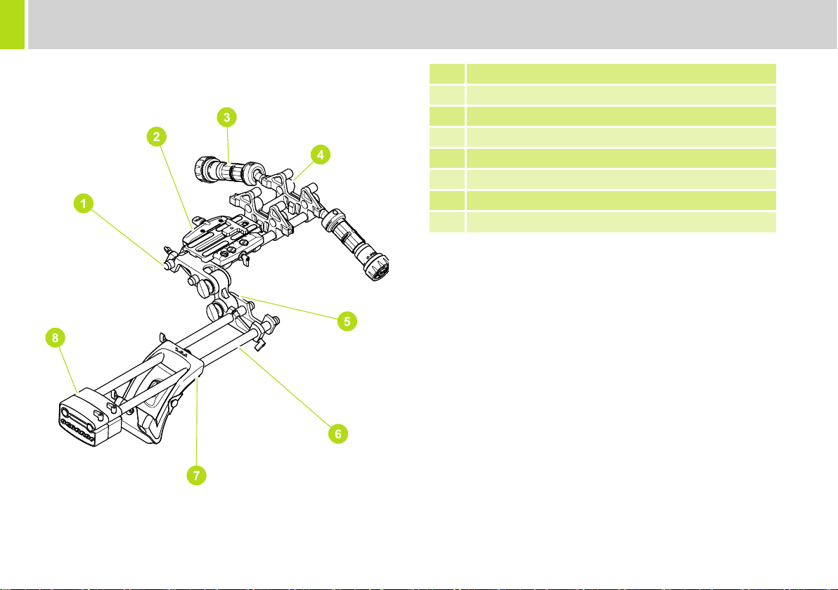
O-Rig Operating Elements
1 12 Inch rods (15mm x 300mm)
2 Baseplate assembly including camera plate
3 O-Grip single module
4 Height adaptor assembly
5 Shoulder offset & angle adjustment
6 18 Inch rods (15mm x 450mm)
7 Body pad assembly
8 Counter weight assembly
4
Page 7
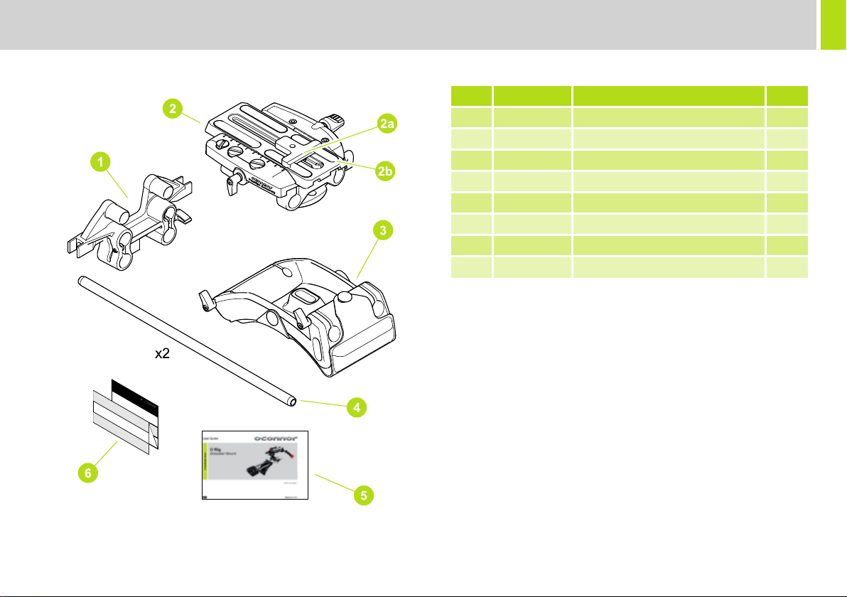
O-Rig Baseplate set
Box Contents
Item Part No Description QTY
1 C1257-1004 Height adaptor assembly 1
2 C1257-1002 Baseplate assembly 1
2a C1257-2025 Anti rotation slide plate 1
2b V4045-1008 Slide plate 1
3 C1257-1003 Body pad assembly 1
4 C1245-2040 18 Inch rods (15mm x 450mm) 2
5 C1257-4980 User guide 1
6 C1257-4981 Camera configuration guide 1
5
Page 8
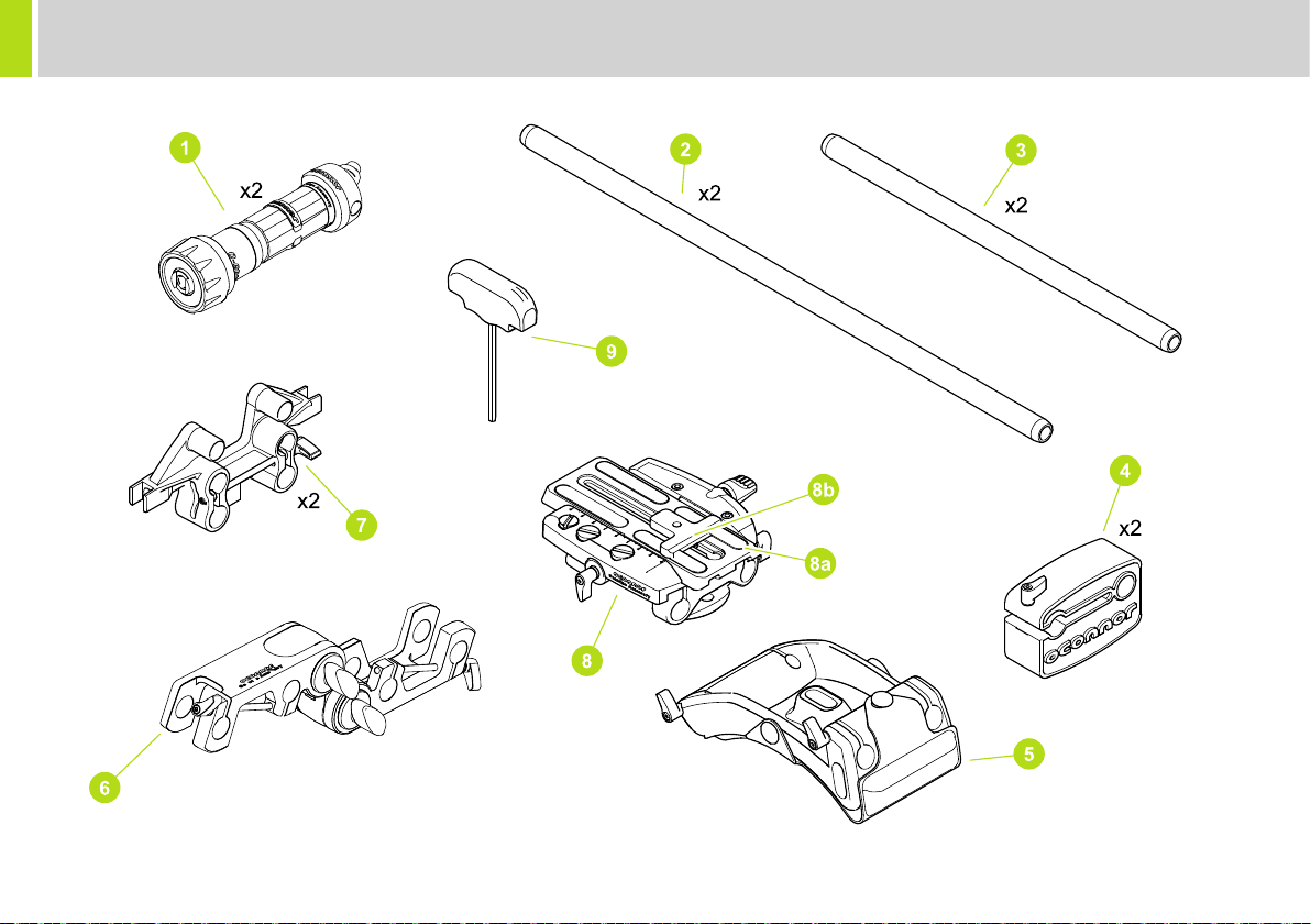
Box contents
O-Rig Pro Kit
6
Page 9

Box Contents
Item Part No Description QTY
1 C1244-1001 O-Grips 2
2 C1245-2040 18 Inch rods (15mm x 450mm) 2
3 C1245-2046 12 Inch rods (15mm x 300mm) 2
4 C1257-1005 Counter weight assembly 2
5 C1257-1003 Body pad assembly 1
6 C1257-1001 Shoulder offset & angle adjustment 1
7 C1257-1004 Height adaptor assembly 2
8 C1257-1002 Baseplate assembly 1
8a V4045-1008 Slide plate 1
8b C1257-2025 Anti rotation slide plate 1
9 M805-008 T bar Allen key, 5mm A/F 1
10 C1257-1850 Storm case 1
11 C1257-4980 User guide 1
12 C1257-4981 Camera configuration guide 1
7
Page 10

Optional Accessories
All box contents are available as accessories, See “Box
contents” on page 6.
Item Part No Description
C1243-0001 O-Box WM set - LWS 15 mm
1
C1243-0002 O-Box deluxe set
C1242-0001 O-Focus DM photo lens pro Kit
2
C1242-0002 O-Focus DM cine lens pro Kit
3 C1244-1003 Rosette adaptor
4 C1257-1006 Body pad
5 C1257-1009 O-Rig head mount
6 C1244-0001 O-Grips single jointed set
7 C1245-2041 24 Inch rods (15 mm x 600 mm)
8 Vocas connecting cables*
9 C1244-0002 O-Grips double jointed set
10 C1244-1004 O-Grips switch module
11 C1244-1001 O-Grips single module
*For Vocas cables see vocas.com
8
Page 11

Installation
Camera Installation
The following section describes the basic assembly of an O-Rig using
all available box contents. Optional accessories have been included for
illustration purposes. For specific configurations, See “Configuration
Examples” on page 15.
WARNING! Risk of finger entrapment. Do not place
fingers between the moving components while adjusting.
9
Page 12

Installation
10
Page 13

Installation
11
Page 14

Installation
12
Page 15

Installation
13
Page 16

Installation
O-Grips Installation
O-Grips can be fitted in various positions on the height adaptor bracket and body pad assembly as well as on accessories such as the O-Box.
14
Page 17

Configuration Examples
The following illustrations provide some examples of how the O-Rig can be configured to suit the user’s requirements. Optional accessories have been
used in some examples.
15
Page 18

Configuration Examples
.
16
Page 19

Configuration Examples
Mounting to a pan and tilt head
The following illustrations provide examples of how the O-Rig can be attached to a pan and tilt head. Optional accessories are used in these examples.
17
Page 20

Maintenance
Cleaning
WARNING! Risk of electric shock. Before carrying out any
cleaning of the O-Rig the camera must be removed.
During normal use the only cleaning required is a periodic wipe-down
with a lint-free cloth. Any dirt that accumulates during storage or
periods of non-use may be removed with a vacuum cleaner.
However, use out-of-doors under adverse conditions will require
special attention. Salt spray should be washed off with fresh water at
the earliest opportunity. Sand and dirt acts as an abrasive and should
be removed using a semi-stiff brush or vacuum cleaner.
Storage
When not being used, it is recommended that the O-Rig is
disassembled and stored in the protective case.
Routine Maintenance
If the O-Rig is left assembled for a period of time, ensure all fixings are
secure before use.
18
Page 21

Technical Specification
O-Rig Pro Kit
Physical Data (Box Only)
Height
7.6 in. (193 mm)
Depth
19.4 in. (493 mm)
Physical Data
Max height
5.3 in. (134 mm)
Max length
28.7 in. (730 mm)
Maximum payload
45 lb (20.4 kg)
Camera fixing method
Wedge Plate, 3/8“ UNC, 1/4” UNC screws
Baseplate adjustment range
1 in. (25 mm)
Camera plate sliding range
4.7 in. (120 mm)
Camera body size range (lens centre to base)
1.25 in. to 4.21 in. (32 mm to 107 mm)
Width
15.4 in. (391 mm)
Weight
8.3 lb (3.75 kg)
Width
17.7 in. (449 mm)
Weight
11.7 lb (5.3 kg)
O-Rig Baseplate Set
Physical Data
Max height
3.9 in. (98 mm)
Max length
18 in. (457 mm)
Maximum payload
45 lb (20.4 kg)
Camera fixing method
Wedge Plate, 3/8“ UNC, 1/4” UNC screws
Baseplate adjustment range
1 in. (25 mm)
Camera plate sliding range
4.7 in. (120 mm)
Camera body size range (lens centre to base)
1.25 in. to 4.21 in. (32 mm to 107 mm)
The assembled dimension of the O-Rig will vary
depending on the configuration.
Width
5.8 in. (148 mm)
Weight
3.8 lb (1.7 kg)
19
Page 22

Technical Specification
Environmental Data (All Parts)
Operating temperature range
-22°F to +158°F (-30°C to +70°C)
Storage temperature range
-40°F to +185°F (-40°C to +85°C)
Operating humidity range
0-90% non condensing
20
Page 23

Page 24

Publication part No C1257-4980/1
OConnor
™
A Vitec Group brand
www.ocon.com
 Loading...