

Page 1

O-Box WM Set
Standard - C1243-0001
Deluxe - C1243-0002
User Guide
User Guide
Page 2

!
Caution
WARNING!
!
If the sunshade is damaged or torn, DO NOT touch the damaged
surfaces. Dispose of safely.
Ÿ DO NOT attempt to move the camera by pulling the flags.
Ÿ DO NOT lift the O-Box WM by the flags, the flag brackets or the O-Grips.
Ÿ DO NOT overload the O-Box WM as a carrying or rigging point.
Ÿ Ensure the lock levers on the flag brackets and the 3-system rod bridge
are firmly tightened.
Ÿ Ensure screws are sufficiently tight when attaching rod brackets or studio
adapter brackets.
Ÿ NEVER use solvents or oil-based cleaners to clean the O-Box WM.
Use mild detergents only. Wipe surfaces with a damp, lint-free cloth.
Ÿ ALWAYS use genuine OConnor parts and accessories with the O-Box WM.
Ÿ When using the O-Box WM as a clamp-on mattebox and/or handheld mount,
DO NOT subject the lens to forces that may damage it.
Particular care should be taken when using still photography lenses intended
for autofocus photography.
Copyright © 2013 The Vitec Group plc
All rights reserved throughout the world. No part of this document may be stored in a retrieval system, transmitted, copied or reproduced in any way, including,
but not limited to, photocopy, photograph, magnetic or other record without the prior agreement and permission in writing from the Vitec Group plc.
Page 3

Caution . . . . . . . . . . . . . . . . . . . . . . . . . . . . . . . . . . . . . . . . . . . . . . . . . . . . . . . . . . . . . . 2
The O-Box Wide Mini . . . . . . . . . . . . . . . . . . . . . . . . . . . . . . . . . . . . . . . . . . . . . . . . . . . 4
Specifications . . . . . . . . . . . . . . . . . . . . . . . . . . . . . . . . . . . . . . . . . . . . . . . . . . . . . . . . . 6
In the box - standard set . . . . . . . . . . . . . . . . . . . . . . . . . . . . . . . . . . . . . . . . . . . . . . . . . 8
In the box - deluxe set . . . . . . . . . . . . . . . . . . . . . . . . . . . . . . . . . . . . . . . . . . . . . . . . . . . 9
Accessories . . . . . . . . . . . . . . . . . . . . . . . . . . . . . . . . . . . . . . . . . . . . . . . . . . . . . . . . . . 11
Components . . . . . . . . . . . . . . . . . . . . . . . . . . . . . . . . . . . . . . . . . . . . . . . . . . . . . . . . . 14
Assembly
assembling the filter frames . . . . . . . . . . . . . . . . . . . . . . . . . . . . . . . . . . . . . . . . 15
assembling the flags . . . . . . . . . . . . . . . . . . . . . . . . . . . . . . . . . . . . . . . . . . . . . 16
assembling the clamp rings . . . . . . . . . . . . . . . . . . . . . . . . . . . . . . . . . . . . . . . . 17
assembling the universal rings. . . . . . . . . . . . . . . . . . . . . . . . . . . . . . . . . . . . . . 18
assembling the bellows ring (donut) . . . . . . . . . . . . . . . . . . . . . . . . . . . . . . . . . 19
mounting onto camera rods . . . . . . . . . . . . . . . . . . . . . . . . . . . . . . . . . . . . . . . . 20
Setup options
Cine Follow Focus . . . . . . . . . . . . . . . . . . . . . . . . . . . . . . . . . . . . . . . . . . . . . . . 21
O-Grips Handgrip System . . . . . . . . . . . . . . . . . . . . . . . . . . . . . . . . . . . . . . . . . 23
Contents
3
Page 4
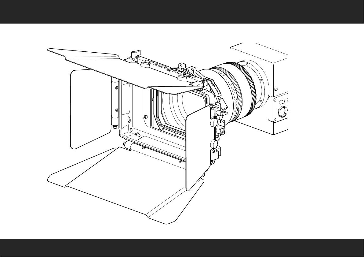
The O-Box Wide Mini
4
Page 5

Congratulations on the purchase of your new OConnor O-Box WM Set!
We want you to get the most from your new O-Box WM compact mattebox and therefore encourage you to
read this user guide to familiarize yourself with its many features, some of which may be new to you. It also
covers essential safety information.
Features and benefits of your new O-Box WM
The O-Box Wide Mini, the first mattebox from OConnor, offers a host of innovative features:
Ÿ highly shock-resistant and durable design
Ÿ large rear clamping interface for lens diameters up to 150 mm
Ÿ clamp rings featuring collet design for high compressibility with no light leaks
Ÿ utility bar or “cheese stick” with provisions for attachment of O-Grips and other
mounting/rigging hardware such as ringlights, top lights, or monitors
Ÿ interface to O-Grips 3-system rod bridge to save rod space in studio configurations
Ÿ easy serviceability
Special features
The OConnor O-Box WM is a compact, two-stage mattebox designed around the 16:9 wide-angle format. The
O-Box WM can be combined with an OConnor Follow Focus, up to six O-Grips and up
to three filters, offering highly flexible configurability and many diverse filtering possibilities in a very compact
package.
New accessories
Oconnor have teamed up with our friends at CINEPARTS to introduce two unique Universal Rings for the
O-Box WM range. Based on an exclusive CINEPARTS design endorsed by OConnor, each ring is
manufactured from aircraft aluminum and holds a seamless high-tech fabric inner that will flex over a variety of
lens diameters. The Universal Rings are supplied in two sizes: 150 to 80 mm, and 114 to 55 mm. These
handy new additions can replace multiple hard reduction rings and are perfect for today's versatile shooter
working with a range of lenses.
5
Page 6

Specifications
O-Box WM Set (C1243-0001) / O-Box WM Deluxe Set (C1243-0002)
O-Box WM
Weight (incl. top flag bracket, LWS rod bracket) . . . . . . . . . . . . . . . . . . . . 0.7 kg (1.54 lbs)
Dimensions (HWD) . . . . . . . . . . . . . . . . . . . . . . . 210 x 242 x 84 mm (8.3 x 9.5 x 3.3 in.)
Height, incl. bottom flag bracket . . . . . . . . . . . . 211 x 242 x 84 mm (8.3 x 9.5 x 3.3 in.)
Width, incl. side flag brackets . . . . . . . . . . . . . 210 x 300 x 84 mm (8.3 x 11.8 x 3.3 in.)
Depth, incl. bellows ring . . . . . . . . . . . . . . . . . 210 x 242 x 106 mm (8.3 x 9.5 x 4.2 in.)
Maximum lens diameter . . . . . . . . . . . . . . . . . . . . . . . . . . . . . . . . . . . . . Ø150 mm (Ø5.9 in.)
Top or bottom flag
Dimensions (width at widest point) . . . . . . . . . . . . . . . . . . . . 166 x 337 mm (6.5 x 13.3 in.)
Filter frames (sets of 2)
to hold square filters . . . . . . . . . . . . . . . . . . . . . . . . . . . . . . . . . . . . . . . . . . . . . . . 4 x 4 in.
to hold rectangular filters . . . . . . . . . . . . . . . . . . . . . . . . . . . . . . . . . . . . . . . . . 4 x 5.65 in.
Overall dimensions (per frame) . . . . . . . . . . . . . . . . . . . . . . . . . 151 x 145 mm (6 x 5.7 in.)
LWS rod bracket
for standard camera rods. . . . . . . . . . . . . . . . . . . . . . . . . . . . . . . . . . . . . Ø15 mm (0.6 in.)
Specifications are subject to change without notice
6
Page 7

Specifications
O-Box WM Deluxe Set (C1243-0002)
Side flags (set of 2)
Dimensions (width at widest point) . . . . . . . . . . . . . . . . . . . . . 115 x 172 mm (4.5 x 6.7 in.)
Side flag brackets (set of 2)
Dimensions (HWD) . . . . . . . . . . . . . . . . . . . . . . . . 105 x 57 x 36 mm (4.1 x 2.2 x 1.4 in.)
Bellows ring (Donut)
Dimensions (width at widest point) . . . . . . . . . . . . . . . . . . . . . 115 x 172 mm (4.5 x 6.7 in.)
Maximum lens diameter . . . . . . . . . . . . . . . . . . . . . . . . . . . . . . . . . . . . . Ø114 mm (Ø4.4 in.)
Reduction ring
Maximum lens diameter . . . . . . . . . . . . . . . . . . . . . . . . . . . . . . . . . . . . . Ø110 mm (Ø4.3 in.)
Universal rings (set of 2)
(150 - 80 mm)
Outer diameter . . . . . . . . . . . . . . . . . . . . . . . . . . . . . . . . . . . . . . . . . . . . Ø150 mm (Ø5.9 in.)
Minimum lens diameter. . . . . . . . . . . . . . . . . . . . . . . . . . . . . . . . . . . . . . . Ø80 mm (Ø3.1 in.)
(114 - 55 mm - threaded)
Outer diameter. . . . . . . . . . . . . . . . . . . . . . . . . . . . . . . . . . . . . . . . . . . . . Ø114 mm (Ø4.4 in.)
Minimum lens diameter. . . . . . . . . . . . . . . . . . . . . . . . . . . . . . . . . . . . . . . Ø55 mm (Ø1.9 in.)
Specifications are subject to change without notice
Only
7
Page 8
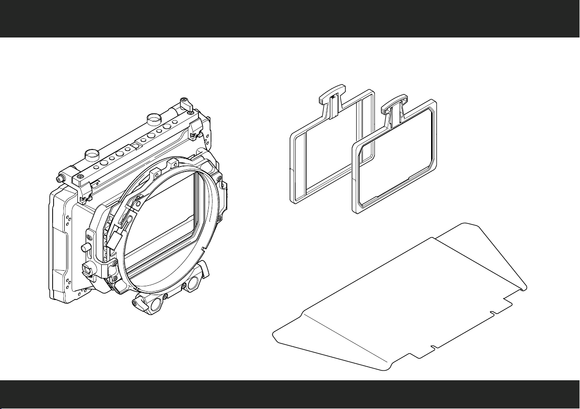
In the box - standard set
O-Box WM Set
C1243-0001
O-Box Wide Mini
Filter Frames 4"x 4"
Set of 2
Filter Frames 4"x 5.65"
Set of 2
Top or Bottom Flag
8
Page 9

In the box - deluxe set
O-Box WM Deluxe Set
C1243-0002
O-Box Wide Mini
Filter Frames 4"x 4"
Set of 2
Filter Frames 4"x 5.65"
Set of 2
Side Flags (Wings)
Set of 2
Side Flag Brackets
Set of 2
9
Page 10

In the box - deluxe set
Bellows Ring
(Donut)
Top or Bottom Flag
Reduction Ring
(114 to 110 mm)
Universal Rings
Set of 2
10
Page 11

Clamp Rings
C1243-1123
C1243-1124
C1243-1125
C1243-1126
Accessories
Studio Adapters
C1243-1118 (19 mm)
C1243-1119 (15 mm)
(for use with rod bridge)
Side Flags (Wings)
Set of 2
C1243-1122
Side Flag Brackets
Set of 2
C1243-1121
Part no.
C1243-1123
C1243-1124
C1243-1125
C1243-1126
Clamp Ring size
(for standard lenses)
150 to 114 mm
150 to 110 mm
150 to 95 mm
150 to 80 mm
11
Page 12

Accessories
Part no.
C1243-2171
C1243-2172
C1243-2173
Reduction Rings
C1243-2171
C1243-2172
C1243-2173
Reduction Ring size
(for use with bellows ring)
114 to 110 mm
114 to 95 mm
114 to 80 mm
O-Grips 3-System
Rod Bridge
C1244-1002
Bellows Ring
(Donut)
C1243-1117
Matching OConnor accessories:
Cine Follow Focus CFF-1 Set
C1241-0001
O-Grips Handgrip System
C1244-1001 (single module)
Bottom Flag Bracket Set
C1243-1127 (flag req.)
12
Page 13

Universal Rings
C1243-1128
C1243-1129
Accessories
Top or Bottom Flag
C1243-2149
Part no.
C1243-1128 150 to 80 mm
Part no.
C1243-1129 114 to 55 mm
Universal Ring size
(for standard lenses)
Universal Ring size
(for use with bellows ring)
13
Page 14

Components
top or bottom flag
sunshade
(mattebox)
side flag
(asymmetric)
flag axle
side flag bracket
knurled flag screws
(hollow)
fixing screw
(for rotatable stage)
O-Grip
mounting point
lock lever
top or bottom bracket
(with utility bar or “cheese stick”)
filter stages
(front / rear)
rear clamping
interface
(Ø150 mm)
bellows ring or “donut”
(optional)
LWS rod bracket
14
Page 15

Assembly – assembling the filter frames
1
Push up the filter spring. Align the
filter in the frame, then release the
spring to fix the filter in place.
A
4" x 4"
B
4" x 5.65"
A
A
OR
rear stage
OR
front stage
B
B
2
Slide the assembled filter frame
Two filter stages are available between the sunshade
and the rear clamping interface: one fixed and one
rotatable stage. Slowly push the filter frame down,
until it audibly ‘clicks’ into place. If you can feel
mechanical resistance, slacken the red fixing screw
a few turns (see step 3).
3
Turn the red fixing screw on the filter stage
clockwise to secure the filter frame in position.
The rear filter frame can be rotated 360°.
Push the head of the filter frame to the left
or right. Tighten the large silver fixing
screw on the front filter stage to
lock the rotation.
into the filter stage.
15
Page 16

assembling the flags
1
If required, turn the lock lever anti-clockwise to unlock the flag axle.
Adjust the axle so the hollow knurled screws point upward.
Turn the knurled screws anti-clockwise a few turns to slacken.
Align the cutouts at the bottom of the flag with the screw threads,
then push the flag into position and tighten the screws.
Adjust the angle of the flag as desired, then tighten the lock
lever clockwise to fix the flag in the desired position.
2
A set of two side flags and two flag brackets
are available as optional accessories. Attach a
flag bracket on either side of the sunshade;
use a 2 mm Allen or hex key and secure the
bracket with the six screws and two rectangular
nuts supplied.
3
Repeat the steps outlined above for the
bottom/top flag also for the side flags
(see step 1). Adjust each flag’s position
as desired, then tighten the lock lever
firmly to fix in position.
16
Page 17

1
Choose a clamp ring to suit your camera lens.
Turn the knurled screw anti-clockwise to widen the
rear clamping interface. The clamp ring uses a
collet design making it easier to compress.
Squeeze the ring adapter slightly, then carefully fit
it into the clamping interface.
assembling the clamp ring
Use the clamp ring to mount the O-Box directly onto the camera lens.
This type of setup is used when carrying the camera on the shoulder
or when mounting it without camera rods. Four standard-size clamp
rings are available (see page 8).
For more information about lens diameters visit OConnor Labs online
at the OConnor website (see OConnor > Labs > ‘Lens Diameters’).
2
Fit the clamp ring over the camera lens. Turn the
knurled screw clockwise to secure the clamp ring to
the lens ensuring that it is firmly attached and that
the mattebox cannot slip.
17
Page 18

assembling the universal ring
Use the universal ring to mount the O-Box directly onto the camera
lens. This type of setup is used when the LWS rod bracket is mounted
to the mattebox.
For more information about lens diameters visit OConnor Labs online
at the OConnor website (see OConnor > Labs > ‘Lens Diameters’).
1
Turn the knurled screw anti-clockwise to widen the
rear clamping interface. Carefully fit the universal
ring into the clamping interface.
18
Turn the knurled screw clockwise to secure the
2
universal ring to the clamping interface. Finally,
using the LWS rod bracket mount the assembled
mattebox on the camera rods and push until it
engages with the camera lens.
Page 19

assembling the bellows ring (donut)
The O-Box WM can be fitted with an optional bellows ring
or “donut” and a reduction ring or universal ring for use
with camera lenses with smaller lens diameters (see page
12 and 13). The donut can accommodate an optional
rotatable round filter (Ø138 mm).
This configuration is suitable for camera rods.
2
Insert the front of the donut into the
clamping interface and push in as far
1
Slacken the large knurled screw on the
rear clamping interface a few turns to
widen the clamping ring. If a round filter
is used, unscrew the retaining ring at the
front of the donut, insert the filter in the
ring groove, then reassemble the donut.
as the tooth profile. Turn the knurled
screw clockwise, until it firmly holds
the donut in the interface.
A
B
3
Insert either the reduction ring [A] or the
universal ring [B] into the donut thread,
then turn clockwise to fix in position.
Finally, using the LWS rod bracket mount
the assembled mattebox on the camera
rods and push until it engages with the
camera lens.
19
Page 20

mounting onto camera rods
The O-Box WM can be fitted with a 15 mm or 19 mm studio adapter
and a 3-system (O-Grips) rod bridge to suit standard camera rods
(see page 9) supporting lightweight to heavy accessory loads.
Turning the lock levers clockwise secures the mattebox on the rods.
For more information about rod adapters visit OConnor Labs online
at the OConnor website (see OConnor > Labs > ‘Rod Standards
Explained’).
20
Remove the LWS bracket (see page 19).
Align the studio adapter and—using a 3 mm
Allen or hex key—tighten the two cap head
screws to secure the adapter.
Mount the 3-system rod bridge. Align the
bridge mounting holes with the adapter
rods, then push the bridge forward onto the
rods. Turn the lock levers clockwise, tighten
firmly to secure the bridge in position.
Page 21

Cine Follow Focus
For precision movement control
the O-Box WM can be partnered
with the Cine Follow Focus.
21
Page 22

adjusting the LWS rod bracket
1
The O-Box WM comes with an LWS rod bracket
attached. Mount the O-Box WM onto camera rods
above the camera using a 3 mm Allen or hex key
to unscrew the two screws holding the LWS rod
bracket and remove the bracket.
The O-Box WM mattebox can be attached to a
camera fitted with an OConnor Follow Focus with
the camera rods mounted above or below the
camera lens. The complete O-Box WM mattebox
assembly, including a suitable lens adapter, is then
mounted flush on camera rods using the 15 mm
LWS rod bracket.
22
2
Attach the LWS rod bracket at the top of the rear
clamping interface. Use the two screws to secure
the bracket in place.
Page 23

O-Grips Handgrip System
The O-Box WM can be equipped with
up to six O-Grips (A), where the system
setup includes a studio adapter and a
3-system O-Grips rod bridge.
The standard setup with a 15 mm LWS
rod bracket offers four mounting points
for O-Grips (B).
A
B
For more information consult the OConnor O-Grips Handgrip System User Guide (publication
part no. C1244-4980) supplied with the product or visit the OConnor website (see page 19).
23
Page 24

OConnor Offices worldwide
ASIA
CHINA
Room 706, Tower B
Derun Building
YongAn Dongli A No. 8
Jianwai Ave.
Chaoyang District
100022 Beijing, China
Tel.: +86 10 8528 8748
Fax: +86 10 8528 8749
JAPAN
P.A. Building 5F
3-12-6 Aobadai
Meguro-ku
Tokyo 153-0042
Japan
Tel.: +81 3 5456 4155
Fax: +81 3 5456 4156
SINGAPORE
6 New Industrial Road
#02-02 Hoe Huat Industrial
Building
Singapore 536199
Tel.:
+65 6297 5776
Fax:
+65 6297 5778
EUROPE
FRANCE
171 Avenue des Gr sillons
92635 Gennevilliers CEDEX
France
Tel.: +33 8 20 82 13 36
Fax: +33 8 25 82 61 81
GERMANY
ä
Geb ude 16
Planiger Stra e 34
55543 Bad Kreuznach
Germany
Tel.: +49 671 483 43 30
Fax: +49 671 483 43 50
Erfurter Straße 16
85386 Eching
Germany
Tel.: +49 89 321 58 200
Fax: +49 89 321 58 227
UK
William Vinten Building
Western Way
Bury St Edmunds
Suffolk IP33 3TB
United Kingdom
Tel.: +44 1284 752 121
Fax: +44 1284 750 560
Sales Fax: +44 1284 757 929
é
ß
www.ocon.com – sales@ocon.com
HEADQUARTERS
2701 N. Ontario St.
Burbank, CA 91504
USA
Tel.: +1 818 847 8666
Fax: +1 818 847 1205
USA
16 Progress Drive
Shelton, CT 06484
USA
Tel.: +1 203 929 1100
Fax: +1 203 925 2684
BRAZIL
Vitec Group Brazil
Vitec Brazil Tecnologias Ltda.
Rua Quintana, 950 – cj. 32
Brooklin
São Paulo, 04569-011
Brazil
Tel.: +55 11 5102 4001
Page 25

Page 26

Connor
O
A V
™
itec Group brand
C1243-4980/2
 Loading...