

Ocmis Irrigazione MR, MRR, MR/1, R1AT15 Instruction Manual

30/11/2015
EN
Models:
MR - MR/1
Models:
MRR - R1AT15
INSTRUCTIONS AND WARNING MANUAL
HOSE REEL TRAVELLING RAINGUNS
MUMR-R1.02 .EN

II
Ocmis Irrigazione S.p.A. – INSTRUCTION AND WARNING MANUAL – Translation of Original Instructions
MUMR-R1.02 .EN - 31/07/2015
Chapter 0
All rights reserved in all countries
Requests for additional copies of this document or technical information on the same, should be sent to:
OCMIS IRRIGAZIONE S.p.A.
Headquarters and Production Facility
41014 CASTELVETRO (MO) ITALIA
Via S.Eusebio, 7
Tel. +39 059 702150
Fax. +39 059 702153
www.ocmis-irrigazione.it
info@ocmis-irrigazione.it
The text and images have been edited with the utmost care, however the Manufacturer reserves the right to amend and/or update the information
herein to correct any typographical errors and/or inaccuracies, without prior notice or obligation.
The content of this manual is strictly technical and is the property of the Manufacturer.
This manual is supplied in paper format.
No part of this manual may be translated and/or adapted and/or reproduced in another form and/or by mechanical, electronic means, by photocopying,
recording or other, without prior written authorisation from the Manufacturer.
The prohibition of copying, disclosing, etc. also applies to the electronic format.
The company protects its proprietary rights according to the law.
Documentation drawn up in compliance with the defi nitions under item 1.7.4 of EC directive 2006/42/EC (Directive on the approximation of the laws
of Member States relating to machinery).
The Manufacturer would like to thank you for purchasing one of its products and recommends reading this manual and all manuals and documents
listed in chapter 9.
In this manual you will fi nd all the information necessary for the proper handling of the machine supplied.
The user is therefore kindly requested to strictly adhere to the warnings herein and to read the manual in its entirety.
Furthermore, we urge you to directly contact the Manufacturer for any spare parts, suggestions on selecting any special equipment or simply for
instructions on the machine you have purchased.
Referencing this manual is supported by the general table of contents shown on the fi rst page and by the Manual layout, which allows topics to be
located immediately.
The chapters are arranged according to a structure that makes the required information easier to fi nd.
A special note at the beginning of the chapter highlights the fact that it deals with topics and provides information of specifi c interest to skilled personnel.
The documentation supplied with the machine consists of the following Instructions and Warning Manual as well as the manuals for the equipment,
machines, partly-completed machinery and components listed in chapter 9 which are an integral part of this manual and for which the same
recommendations/requirements set out herein apply.
The instructions contained in this manual are: TRANSLATION OF ORIGINAL INSTRUCTIONS.

III
Ocmis Irrigazione S.p.A. – INSTRUCTION AND WARNING MANUAL – Translation of Original Instructions
MUMR-R1.02 .EN - 31/07/2015
Chapter 0
ORGANISATION OF THE DOCUMENTATION
The instruction and warning manual is organised as follows:
a) General machine manual, the chapter structure of which is set out below
Operating instructions manual
Chapter 0
Contents
• Contents of the manual
Chapter 1
General information
• Manual composition
• Warranty
• Terminology and abbreviations used
• General remarks
Chapter 2
Technical specifi cations and Layout
• Technical specifi cations
• Identifi cation code
• General Layout
Chapter 3
Description
• Description of the machine and installed
parts
• Confi guration by type
Chapter 4
Safety
• Technical standards applied
• Certifi cation of the machine
• Safety devices applied to the machine
• Disconnection of power sources
• Residual risks and warning plates
Chapter 5
Transport and Installation
• Packaging and transport
• Assembly and placement
• Connections
• Checks and inspections after installation
Chapter 6
Use and Operation
• Preliminary information
• Procedures for operating
• Operator interface devices
Chapter 7
Maintenance
• General maintenance information
• Personnel in charge of maintenance
• Maintenance plan
• Cleaning
• Maintenance procedures
Chapter 8
Troubleshooting - Diagnostics - Solutions
• Troubleshooting
• Diagnostics and Solutions
Chapter 9
List of annexes
• Reference to diagrams, manuals and
relevant documentation for component
equipment which makes up the supplied
machine
Chapter 10
Lists of Spare Parts
• Lists of machine spare parts recommended
by the Manufacturer for the machine
b) Specifi c Manuals for the main Process Units designed by the Manufacturer.
c) Instruction manuals drawn up by the respective OEMs for the main trade systems purchased by the Manufacturer and integrated into the machine.
d) Circuit diagrams (oil hydraulic, electrical, etc.), spare part list, setting up charts, etc.

IV
Ocmis Irrigazione S.p.A. – INSTRUCTION AND WARNING MANUAL – Translation of Original Instructions
MUMR-R1.02 .EN - 31/07/2015
Chapter 0
CONTENTS
1 GENERAL INFORMATION ........................................................................................................................................ 1
1.1 WARNINGS FOR THE BUYER ........................................................................................................................................... 1
1.2 INTRODUCTION ................................................................................................................................................................. 2
1.3 MANUFACTURER'S ADDRESS ......................................................................................................................................... 3
1.4 SAFETY RULES SET OUT IN THE MANUAL..................................................................................................................... 3
1.5 GLOSSARY OF TERMS USED .......................................................................................................................................... 3
1.6 PERSONNEL QUALIFICATIONS ........................................................................................................................................ 5
1.7 SYMBOLS USED WITHIN THE MANUAL .......................................................................................................................... 5
1.8 SYMBOLS USED WITHIN THE MANUAL .......................................................................................................................... 6
1.9 DESCRIPTION OF PERSONAL PROTECTION EQUIPMENT (PPE) ................................................................................ 9
1.10 MANUAL LANGUAGE ....................................................................................................................................................... 10
1.11 MACHINE HANDLING ......................................................................................................................................................10
1.12 WARRANTY ..................................................................................................................................................................... 10
2 TECHNICAL DESCRIPTION OF THE MACHINE .....................................................................................................11
2.1 DESCRIPTION OF MAIN PARTS ..................................................................................................................................... 11
2.2 DESCRIPTION OF OPTIONAL PARTS ............................................................................................................................ 14
2.3 DESCRIPTION OF RAINGUN TROLLEYS ....................................................................................................................... 16
2.3.1 DESCRIPTION OF MAIN PARTS AND WHEEL WIDTH .................................................................................................................... 16
2.3.2 DESCRIPTION OF THE MAIN ACCESSORIES................................................................................................................................. 20
2.3.3 DESCRIPTION OF OPTIONAL ACCESSORIES ................................................................................................................................ 20
2.4 TECHNICAL DATA ............................................................................................................................................................21
2.4.1 MACHINE WEIGHTS BASED ON MODEL ........................................................................................................................................ 21
2.4.2 DIMENSIONS OF MACHINES WITH 2 WHEELS .............................................................................................................................. 23
2.4.3 WHEEL SIZE AND TECHNICAL SPECIFICATIONS .......................................................................................................................... 24
2.4.4 RAINGUN TROLLEY WHEEL SIZE AND TECHNICAL SPECIFICATIONS ....................................................................................... 24
2.4.5 NOISE LEVEL ..................................................................................................................................................................................... 24
2.5 DESCRIPTION OF CONTROLS ....................................................................................................................................... 24
2.5.1 MECHANICAL CONTROLS ON THE MACHINE ............................................................................................................................... 24
2.5.2 COMPUTER CONTROLS ................................................................................................................................................................. 26
3 MACHINE DESCRIPTION ....................................................................................................................................... 27
3.1 INTENDED USE ................................................................................................................................................................ 27
3.2 UNAUTHORISED USE .....................................................................................................................................................27
3.3 MACHINE DESCRIPTION ................................................................................................................................................28
3.4 STANDARD OUTFITTING FOR THE MACHINE .............................................................................................................. 29
3.5 ACCESSORIES THAT MAY BE SUPPLIED WITH THE MACHINE.................................................................................. 29
4 SAFETY ................................................................................................................................................................... 31
4.1 GENERAL INFORMATION ................................................................................................................................................ 31
4.1.1 PERSONNEL TRAINING .................................................................................................................................................................... 31
4.1.2 DIRECTIVES APPLIED AND TECHNICAL STANDARDS OF REFERENCE ..................................................................................... 32
4.1.3 CERTIFICATION OF THE MACHINE ................................................................................................................................................. 32
4.1.4 INTENDED USES AND APPLICATION LIMITS.................................................................................................................................. 35
4.1.5 HAZARDOUS AREAS ........................................................................................................................................................................ 35
4.1.6 ENVIRONMENTAL OPERATING CONDITIONS ................................................................................................................................ 35
4.1.7 VIBRATIONS....................................................................................................................................................................................... 36
4.1.8 NOISE ................................................................................................................................................................................................. 36
4.1.9 ELECTROMAGNETIC EMISSIONS ................................................................................................................................................... 36
4.2 DISPOSAL OF WASTE MATERIALS ................................................................................................................................ 37
4.2.1 INSTRUCTIONS FOR SPECIAL WASTE ........................................................................................................................................... 37
4.3 SAFETY DEVICES APPLIED TO THE MACHINE ............................................................................................................ 37
4.3.1 CONTROL LEVERS ........................................................................................................................................................................... 37
4.3.2 FIXED GUARDS ................................................................................................................................................................................. 38
4.3.3 POWER DISCONNECTION ............................................................................................................................................................... 39
4.4 RESIDUAL RISKS ............................................................................................................................................................. 39
4.4.1 IMPACT AND CRUSHING: ................................................................................................................................................................. 39
4.4.2 SHEARING: ........................................................................................................................................................................................ 39
4.4.3 FIRE: ................................................................................................................................................................................................... 39
4.4.4 EXPLOSIVE ATMOSPHERE: ............................................................................................................................................................. 40
4.4.5 BLINDING: .......................................................................................................................................................................................... 40
4.4.6 ENTANGLEMENT: .............................................................................................................................................................................. 40
4.4.7 FALLING, FLYING OBJECTS: ............................................................................................................................................................ 40
4.4.8 SLIPPING: .......................................................................................................................................................................................... 40
4.4.9 WHIPLASH EFFECT: .......................................................................................................................................................................... 41
4.4.10 TRIPPING: .......................................................................................................................................................................................... 41
4.4.11 CIRCUIT FAILURES: .......................................................................................................................................................................... 41
4.4.12 LOSS OF STABILITY: ......................................................................................................................................................................... 41
4.4.13 LIGHTING: .......................................................................................................................................................................................... 41
4.4.14 BURN/SCALDING HAZARD: .............................................................................................................................................................. 41
4.4.15 LIGHTNING - ELECTROCUTION HAZARD: ...................................................................................................................................... 41
4.4.16 NOISE: ................................................................................................................................................................................................ 42
4.4.17 VIBRATIONS:...................................................................................................................................................................................... 42

V
Ocmis Irrigazione S.p.A. – INSTRUCTION AND WARNING MANUAL – Translation of Original Instructions
MUMR-R1.02 .EN - 31/07/2015
Chapter 0
4.4.18 RISKS DUE TO HANDLING: .............................................................................................................................................................. 42
4.4.19 RISKS CAUSED TO PUBLIC OR PRIVATE ROAD CIRCULATION OR OTHER PRIVATE AREAS; ................................................. 42
4.5 ADDITIONAL DANGER WARNINGS ................................................................................................................................ 43
4.6 ADDITIONAL WARNINGS AND REQUIREMENTS .......................................................................................................... 44
4.7 WARNING NOTICES ........................................................................................................................................................ 46
4.8 POSITION AND MEANING OF THE OPERATION PICTOGRAMS ................................................................................. 47
4.9 POSITION AND MEANING OF THE WARNING PICTOGRAMS ..................................................................................... 48
4.10 CONSIDERATIONS AND SAFETY WARNINGS FOR OILS AND LUBRICANTS ............................................................50
4.10.1 CLASSIFICATION AND DESCRIPTION OF THE DEGREE OF HAZARDOUSNESS OF PRODUCTS ............................................ 50
4.10.2 FIRST AID MEASURES ...................................................................................................................................................................... 50
4.10.3 FIRE PREVENTION MEASURES ...................................................................................................................................................... 50
4.10.4 MEASURES FOR ACCIDENTAL SPILLAGE ...................................................................................................................................... 50
4.10.5 HANDLING AND PERSONAL PROTECTION .................................................................................................................................... 50
4.10.6 TOXICOLOGICAL INFORMATION ..................................................................................................................................................... 50
4.10.7 ENVIRONMENTAL INFORMATION ON STORAGE AND DISPOSAL ............................................................................................... 50
5 INSTALLATION ........................................................................................................................................................ 51
5.1 GENERAL INFORMATION ................................................................................................................................................ 51
5.2 TERMS OF SUPPLY ......................................................................................................................................................... 51
5.2.1 PACKAGING AND TRANSPORT........................................................................................................................................................ 51
5.3 PREPARATION OF THE OPERATING ENVIRONMENT .................................................................................................. 51
5.3.1 GENERAL INFORMATION ................................................................................................................................................................. 51
5.3.2 PROFESSIONAL PROFILES AND MANDATORY PPE ..................................................................................................................... 52
5.3.3 CHOICE OF PREMISES AND ASSESSMENT OF INSTALLATION REQUIREMENTS ..................................................................... 52
5.3.4 LOADING, UNLOADING, LIFTING AND HANDLING PROCEDURES .............................................................................................. 52
5.3.5 HOOKING LIFTING POINTS .............................................................................................................................................................. 53
5.4 ASSEMBLY AND PLACEMENT ........................................................................................................................................ 55
5.5 LUBRICATION OF MACHINE PARTS .............................................................................................................................. 55
5.6 CHECKS AND INSPECTIONS PRIOR TO STARTING UP ............................................................................................... 56
5.6.1 GENERAL CHECKS ON MECHANICAL ASSEMBLIES .................................................................................................................... 56
5.6.2 CHECK ON SAFETY SYSTEMS ........................................................................................................................................................ 56
5.7 DECOMMISSIONING ........................................................................................................................................................ 57
6 USE AND OPERATION - GENERAL INFORMATION.............................................................................................. 58
6.1 PROFESSIONAL PROFILES AND MANDATORY PPE .................................................................................................... 58
6.2 CHECK PRIOR TO STARTING WORK ............................................................................................................................. 58
6.2.1 PREOPERATIVE INSPECTION ......................................................................................................................................................... 58
6.2.2 FUNCTIONAL TESTS WITH REELED IN HOSE AND MACHINE STATIONARY .............................................................................. 59
6.2.2.1 TESTS ON MANUAL AND/OR OIL HYDRAULIC ACTUATIONS FOR MACHINE PLACEMENT FUNCTIONS ................................59
6.2.2.2 TESTS ON OPERATION CONTROLS WITH MACHINE STATIONARY ............................................................................................ 59
6.2.3 OPERATING SITE INSPECTION ....................................................................................................................................................... 65
6.3 REMOVAL FOR PLACEMENT IN THE FIELD .................................................................................................................. 65
6.3.1 TOWING THE MACHINE .................................................................................................................................................................... 65
6.4 PLACEMENT OF THE MACHINE IN THE FIELD ............................................................................................................. 66
6.5 CHECKS TO BE PERFORMED WITH UNWOUND HOSE AND PRIOR TO STARTING IRRIGATION ........................... 67
6.6 STARTING WORK ............................................................................................................................................................ 68
6.6.1 ADJUSTMENT OF AUTOMATIC SPEED CORRECTION .................................................................................................................. 68
6.6.2 QUICK HOSE WINDING .................................................................................................................................................................... 69
6.7 END OF WORK AND PREPARING TO TOW ................................................................................................................... 69
6.8 USE OF THE MECHANICAL OR ELECTRICAL SLOW CLOSING INLET VALVE (OPTIONAL FEATURE) .................... 70
6.8.1 ADJUSTMENT OF SLOW CLOSING INLET VALVE .......................................................................................................................... 70
6.8.2 OPERATION TO BE PERFORMED ON THE MACHINE PRIOR TO MOVING IT, IF IT IS EQUIPPED WITH SLOW CLOSING INLET
VALVE ................................................................................................................................................................................................. 70
6.9 USE OF THE MECHANICAL OR ELECTRICAL DISCHARGE VALVE (OPTIONAL FEATURE) ...................................... 70
6.10 BOOSTER UNIT WITH MOTOR PUMP MR - MR/1 - MRR ............................................................................................. 71
7 MAINTENANCE ...................................................................................................................................................... 74
7.1 GENERAL INFORMATION ................................................................................................................................................ 74
7.1.1 PROFESSIONAL PROFILES AND MANDATORY PPE ..................................................................................................................... 74
7.2 PERSONNEL IN CHARGE OF MAINTENANCE .............................................................................................................. 75
7.3 GENERAL SAFETY PRECAUTIONS................................................................................................................................75
7.3.1 DANGER NOTES ............................................................................................................................................................................... 75
7.3.2 WARNING NOTES ............................................................................................................................................................................. 77
7.4 RECOMMENDATIONS CONCERNING MAINTENANCE ................................................................................................. 77
7.4.1 OPERATIONS CONNECTED WITH EXTENDED DOWNTIMES ....................................................................................................... 77
7.4.2 MACHINE CHECK PROCEDURE WITH MOTOR OFF...................................................................................................................... 78
7.4.2.1 HYDRAULIC SYSTEM OIL ................................................................................................................................................................. 78
7.4.2.2 PIPING ................................................................................................................................................................................................ 78
7.4.2.3 FUEL SUPPLY SYSTEM ....................................................................................................................................................................78
7.4.2.4 BATTERY CHECK ..............................................................................................................................................................................79
7.4.2.5 TYRES ................................................................................................................................................................................................ 79
7.4.2.6 WHEEL RIMS ..................................................................................................................................................................................... 80
7.4.2.7 SCREW TIGHTENING TORQUES ..................................................................................................................................................... 80
7.5 DESCRIPTION OF THE MAINTENANCE PLAN .............................................................................................................. 81
7.6 CLEANING OPERATIONS ................................................................................................................................................ 81

VI
Ocmis Irrigazione S.p.A. – INSTRUCTION AND WARNING MANUAL – Translation of Original Instructions
MUMR-R1.02 .EN - 31/07/2015
Chapter 0
7.7 LUBRICATION PLAN ........................................................................................................................................................82
7.7.1 RECOMMENDED LUBRICANTS: OILS AND GREASES .................................................................................................................. 82
7.7.2 REQUIRED LUBRICANT AMOUNTS ................................................................................................................................................. 82
7.7.3 MACHINE PARTS TO BE LUBRICATED WITH GREASE ................................................................................................................. 83
7.8 MAINTENANCE PLAN ...................................................................................................................................................... 85
7.8.1 FILLING IN CRITERION ..................................................................................................................................................................... 85
7.8.2 LIST OF MAINTENANCE SHEET AND FREQUENCY ...................................................................................................................... 86
7.8.2.1 EVERY 200 HOURS ........................................................................................................................................................................... 86
7.8.2.2 BEFORE STORAGE AT THE END OF THE SEASON ....................................................................................................................... 86
7.8.2.3 EVERY YEAR BEFORE THE START OF THE IRRIGATION SEASON ............................................................................................. 87
7.8.3 MAINTENANCE INFORMATION ON OPTIONAL ACCESSORIES .................................................................................................... 87
7.8.3.1 DISCHARGE VALVE ........................................................................................................................................................................... 87
7.8.3.2 SLOW CLOSING INLET VALVE ......................................................................................................................................................... 87
7.8.3.3 INTERNAL COMBUSTION ENGINE .................................................................................................................................................. 87
7.8.3.4 BATTERY ............................................................................................................................................................................................ 87
7.8.3.5 PHOTOVOLTAIC PANEL .................................................................................................................................................................... 87
8 GENERAL DESCRIPTION OF FAILURES .............................................................................................................. 88
8.1 LIST OF FAILURES - CAUSES - SOLUTIONS ................................................................................................................. 88
9 ANNEXES ................................................................................................................................................................ 91
10 SPARE PARTS ......................................................................................................................................................... 91
10.1 SPARE PART ORDER ...................................................................................................................................................... 91
1
Ocmis Irrigazione S.p.A. – INSTRUCTION AND WARNING MANUAL – Translation of Original Instructions
MUMR-R1.02 .EN - 31/07/2015
CHAPTER 1 - General information
GENERAL
INFORMATION
CH. 1
1 GENERAL INFORMATION
1.1 WARNINGS FOR THE BUYER
The manual, like the CE certifi cate of conformity, is an integral part of the machine and must always accompany it each time it is transferred or resold.
It is the user's responsibility to maintain this documentation intact, to allow it to be referenced throughout the entire service life of the machine.
In the event of loss or destruction, a copy may be obtained from the Manufacturer, specifying exactly the model, serial number and year of production.
The manual refl ects the state of the art at the time of supply. The undersigned company reserves the right to make any amendment to its products it
may deem appropriate, without being obliged to upgrade manuals and machines for previous production batches.
The Manufacturer disclaims any liability for production faults and damage caused by the machine to property, persons and animals in the following
cases:
• Misuse of the machine or use with functions other than those for which it has been constructed.
• Use by unsuitable or unauthorised personnel.
• Faults in oil hydraulic, water supply, etc.
• Non compliance with technical power supply specifi cations.
• Insuffi cient or poor periodic maintenance.
• Incorrect installation at the site or location it is intended for.
• Use of inadequate hoses or delivery hoses and/or hoses unsuitable for the pressures the machine has been designed for.
• Modifi cations or procedures not agreed with and/or authorised by the Manufacturer.
• Use in a non-Agricultural setting.
• Use of non-original parts or parts that are not specifi c to the model.
• Use by persons under the age of 18.
• Total or partial failure to comply with these instructions.
• Use not complying with the machine safety laws and/or with the safety standards set forth by specifi c European and/or national laws in force.
• Use of trailer or transfers on public roads without Road Use Approval.
• Exceptional events.
Responsibility for the application of the safety requirements set out below lies with the user, who must ascertain that authorised personnel:
• are qualifi ed to perform the required activity
• are familiar and strictly comply with the requirements herein
• are familiar with and apply general safety rules applicable to the machine and those in force at the utilisation site
• are familiar with the safety rules concerning the risks arising from treatment of the products the machine is intended for.
It is a mandatory requirement for the technical maintenance personnel to have read and understood this manual and the documentation
set out in chapter 9 which is an integral part thereof, to be familiar with and skilled in the basic principles of mechanics, hydraulics, water
engineering and electricity, to be familiar with connection and wiring procedures and with the symbols used in mechanical and fl uid power
diagrams, and to be experienced in using equipment and machinery.
Failure to comply with the safety standards may cause injury to personnel and damage the components and control unit of the machine.
Reading this manual, albeit comprehensively, cannot in any case replace adequate operator expertise.
The user may contact the Manufacturer at any time to request information additional to that contained herein, as well as to contribute proposed
improvements.
CAUTION
We hereby remind you that the documentation provided by the Manufacturer solely concerns the machine supplied to the user
by the Manufacturer and not the overall system/assembly within which it may be installed and used.
DANGER
Due to the process features, improper machine use and installation involve signifi cant risks and are forbidden.
CAUTION
It is the user's unequivocal responsibility to complement the instructions herein with any operating procedures in force in the
place of the machine's use and to provide all additional information to the personnel in charge of machine use and maintenance.

2
Ocmis Irrigazione S.p.A. – INSTRUCTION AND WARNING MANUAL – Translation of Original Instructions
MUMR-R1.02 .EN - 31/07/2015
CHAPTER 1 - General information
This manual is an integral part of the machine it refers to and contains the required information for:
• Properly raising operator awareness of relevant safety issues;
• Machine handling under safe conditions;
• Thorough knowledge of its operation and limitations;
• Its proper use under safe conditions;
• Performing maintenance procedures in a correct and safe manner;
• Dismantling the machine under safe conditions and complying with applicable standards protecting workers' health, safety and the environment.
Operators must be carefully trained on operation and proper use of the installed safety devices.
DANGER
The machine must be exclusively used by skilled operators trained on the procedures, and it is to be used complying with the
recommendations herein.
The user is also responsible for ensuring that - in the event this document should undergo any amendments by the Manufacturer - only updated
Manual versions are actually present at the utilisation sites.
All the manuals and documentation set out in chapter 9 are an integral part of this manual.
DANGER
Hazardous use of the machine may cause severe injury to the operator and/or persons near the operations area.
It is therefore indispensable to adhere to the provisions of this manual.
Operators and personnel in charge of maintenance must read this manual before starting work.
The manual must be kept on board the machine, for referencing and periodic review by all personnel who need to operate it.
The machines in question CANNOT be towed on public roads unless they are provided with proper Road Use Approval issued
and recognised by the Body responsible for issuing the Registration Document in the country where they are used.
When the machines are provided with Road Use Approval for towing on public roads, it is indispensable to adhere to the rules
and requirements set out in the Registration Document issued by the Body responsible of the country where they are used.
1.2 INTRODUCTION
In order to assure the utmost operating reliability, the Manufacturer has performed careful selection of the materials and components to be employed
in constructing the machinery, submitting it to proper testing before delivery. Its good performance over time depends on proper use and adequate
preventive maintenance, according to the instructions herein and in the documentation supplied with the machine.
All construction elements, coupling and control parts have been designed and constructed with a degree of safety such as to be able to withstand
abnormal strain or at any rate higher than those specifi ed.
The materials are of the best quality and their treatment in the company, storage and use in the shop are constantly monitored, in order to assure the
absence of damage, deterioration or malfunction.
Despite all design and construction solutions, for the aims of correct use, safety, durability and reliability of the machine, it is crucial to carefully follow
the Manufacturer's instructions and install and use the same in accordance with these instructions and with the legal requirements in force in the
country/site of use of the machine.
The purpose of this manual is to provide technical information to the personnel in charge of using and maintaining the machine produced by the
Manufacturer.
The instructions herein are aimed at operators with adequate knowledge in the fi eld of mechanics, hydraulics, water engineering and electrics.
The instruction and warning manual contains the information required to understand the methods for installing, operating and properly using the
machine, specifi cally: technical description of the various functional assemblies, safety equipment and systems, operation, use of the instrumentation
and interpretation of any diagnostics signals, main procedures and information concerning maintenance operations.
For proper use of the machine it is assumed that the work environment complies with applicable regulations on health and safety.
CAUTION
Before proceeding with machine installation or making it operational, using or performing maintenance on the machine, read this
manual very carefully and faithfully follow the instructions and recommendations herein.
Training is also recommended for the above personnel in order to assure perfect familiarity and knowledge of the machine.

3
Ocmis Irrigazione S.p.A. – INSTRUCTION AND WARNING MANUAL – Translation of Original Instructions
MUMR-R1.02 .EN - 31/07/2015
CHAPTER 1 - General information
1.3 MANUFACTURER'S ADDRESS
INSTRUCTIONS TO REQUEST SERVICING
The machine is a product serviced worldwide with direct coordination with the Manufacturer's technical support.
The undersigned Company is always available to meet Customer needs concerning any kind of information or clarifi cation on installation, use,
maintenance, etc.
The Customer should ask questions in a clear language, with references to this manual and always provide the details shown on the machine's
identifi cation data plate.
Any request for information or servicing at the Customer's premises or for clarifi cations concerning technical aspects of this document must be sent to:
OCMIS IRRIGAZIONE S.p.A.
Headquarters and Production Facility
41014 CASTELVETRO (MO) ITALIA
Via S.Eusebio, 7
Tel. +39 059 702150
Fax. +39 059 702153
www.ocmis-irrigazione.it
info@ocmis-irrigazione.it
In particular, the Customer must provide the following data to the manufacturer:
• type of machine, serial number, year of installation
• faults detected
• exact address of the site/facility where the machine is installed
• contact person.
1.4 SAFETY RULES SET OUT IN THE MANUAL
The safety requirements, instructions, rules and relevant notes, set out in the various chapters of the manual, have the purpose of defi ning behaviour
and a set of obligations one should adhere to in performing the various activities, in order to operate under safe conditions for personnel, the
equipment and the surrounding environment.
The safety rules herein are aimed at all authorised personnel, instructed and assigned to perform the following various operations:
• transport
• installation
• operation
• use
• handling
• maintenance
• cleaning
• decommissioning and dismantling
which represent the intended methods of use for the machine in question.
SUPPLEMENTARY INFORMATION
Please refer to chapter 4 for further information concerning training.
1.5 GLOSSARY OF TERMS USED
The manuals employ technical terminology or terminology having a meaning different from common usage.
below is an explanation of the terms and abbreviations used:
HAZARD: (Annex I, 1.1.1 Directive 2006/42/EC).
a potential source of injury or damage to health;
DANGER ZONE: (Annex I, 1.1.1 Directive 2006/42/EC).
any zone within and/or around the system where the presence of an exposed person represents a risk for that person's health and safety;
EXPOSED PERSON (Annex I, 1.1.1 Directive 2006/42/EC).
Any person wholly or partially in a danger zone;
RISK: (Annex I, 1.1.1 Directive 2006/42/EC).
a combination of the likelihood and severity of an injury or damage to health that may arise in a hazardous situation;
GUARD: (Annex I, 1.1.1 Directive 2006/42/EC).
a part of the machinery used specifi cally to provide protection by means of a physical barrier;

4
Ocmis Irrigazione S.p.A. – INSTRUCTION AND WARNING MANUAL – Translation of Original Instructions
MUMR-R1.02 .EN - 31/07/2015
CHAPTER 1 - General information
PROTECTIVE DEVICE: (Annex I, 1.1.1 Directive 2006/42/EC).
a device (other than a guard) which reduces the risk, either alone or in conjunction with a guard;
INTENDED USE: (Annex I, 1.1.1 Directive 2006/42/EC).
the use of the machinery in accordance with the information provided in the instructions for use;
MISUSE: Use of the machinery in a way not intended in the instructions for use, but which may result from readily predictable human behaviour;
RESIDUAL HAZARD: Hazard that has not been possible to eliminate or reduce by design, against which the guards are not (partially or totally)
effective;
The Manual (chapter 4) contains the residual hazards and information, instructions and warnings/requirements for managing Residual Risks, the
responsibility for which must lie with the user (Ref. UNI EN ISO 12100:2010).
HOSE REEL TRAVELLING RAINGUN: Type of movable irrigation machine equipped with a fi xed structure with a hose reel, onto which a fl exible
hose is wound through which irrigation water fl ows, towing a movable trolley onto which the distribution system is secured, generally consisting of a
long range raingun (Ref. 3.1 EN 908).
LONG RANGE RAINGUN: Large-sized raingun used on hose reel travelling rainguns and on other systems (Ref. 3.2 EN 908).
WINDING: One of the operations performed by the hose reel travelling raingun while it is irrigating. The hose reel travelling raingun progressively reels
in all the fl exible polyethylene hose onto the drum, allowing the long range raingun to move evenly through the plot to be irrigated. When the long range
raingun reaches the machine, reeling in is completed and the machine stops (Ref. 3.3 EN 908).
GUIDE SYSTEM: Side hose guide device to wind it evenly with close-knit loops (Ref. 3.4 EN 908).
GUIDE SYSTEM ACTUATION DEVICE: Mechanism that powers the guide system assuring even winding of the hose in layers (Ref. 3.5 EN 908).
COVER AREA: Range of various turret positions corresponding to all possible orientations (Ref. 3.6 EN 908).
For a comprehensive description of the terminology used please refer to the defi nitions contained in annex I of machine directive 2006/42/EC and
standards EN ISO 12100 and EN 908.
PERSONAL PROTECTION EQUIPMENT (PPE): Personal protection equipment refers to any equipment intended to be worn and/or used by the
worker for the purpose of protecting them from one or more risks likely to threaten their safety or health during work, as well as any item or accessory
intended for that purpose.
Personal protection equipment does not include the following:
• Ordinary work clothes and uniforms not specifi cally designed to protect the worker's health and safety;
USER: User (entrepreneur / fi rm) refers to whoever employs the machine for the intended use, or entrusts its use to skilled and suitably trained
persons.
MAN MACHINE INTERACTION: Any situation where an operator interacts with the machine in any operating stage at any time during its service life.
MACHINE STATUS: The machine status includes operating modes, e.g. running, dead-man control, stop, etc., the condition of the safety devices
fi tted on the machine such as the guards included, the guards bypassed, the emergency stop, the type of insulation from energy sources, etc.
In this manual, the term operator or personnel in charge is used to refer to the person or persons authorised to perform machine installation as well
as those intended to commission it, operate it and carry out maintenance in compliance with the classifi cation set out herein.
The defi nition of machine as set forth under art.2 of directive 2006/42/EC and included below should be deemed as consisting of the whole: hose reel
on frame with wheeled traveller, equipped with polyethylene hose and raingun trolley with or without optional accessories.
The term Manufacturer used in this manual refers to the company specifi ed under paragraph 1.3.

5
Ocmis Irrigazione S.p.A. – INSTRUCTION AND WARNING MANUAL – Translation of Original Instructions
MUMR-R1.02 .EN - 31/07/2015
CHAPTER 1 - General information
1.6 PERSONNEL QUALIFICATIONS
The symbols shown in the table are used in the Manuals next to the notes in bold to indicate important information/requirements concerning the
required professional qualifi cation.
PROFESSIONAL ROLES
Symbol Description
OPERATOR: User's personnel trained and qualifi ed for the use and operation of the machine for production purposes for the
activities it has been constructed and supplied for.
They must be able to perform all the required procedures for proper machine operation and for their own safety and that of any
assistants.
They must have proven experience in proper use for this type of machine for the work involved.
In the event of any doubts they must report any fault to their supervisor.
They are not authorised to perform any maintenance activity.
LIFTING AND HANDLING EQUIPMENT DRIVER: Personnel qualifi ed for the use of equipment for lifting and handling materials
and machines (strictly adhering to instructions issued by the Manufacturer), in compliance with applicable laws in force in the
machine user's country.
MECHANICAL MAINTENANCE TECHNICIAN: Qualifi ed technician able to run the machine as the operator, to work on
mechanical parts, internal combustion engine, oil hydraulic and water systems for adjustments, maintenance, repairs, and who is
also able to read water and hydraulic diagrams, technical drawings and spare part lists.
In extraordinary cases, they are authorised to operate the machine with reduced safety devices.
They are not qualifi ed to work on live electrical installations (if present).
Where necessary, they may issue instructions to the operator for proper use of the machine for production purposes.
ELECTRICAL MAINTENANCE TECHNICIAN: Qualifi ed technician able to run the machine as the operator, to work on electrical
adjustments and systems for maintenance, repairs, and replacement of worn parts.
They are also able to read wiring diagrams and to check the correct functional cycle.
They are able to work on live electrical boards, junction boxes, control equipment, etc. only if they are suitable (Instructed Person)
(See EN50110-1).
Where necessary, they may issue instructions to the operator for proper use of the machine for production purposes.
MANUFACTURER'S TECHNICIAN: A technician qualifi ed by the Manufacturer and/or their distributor for complex operations, as
they are familiar with the machine's construction manufacturing cycle.
This person must act according to the user's requirements.
Their skills must be, as the case may be, in mechanics and/or electrics and/or electronics and/or software.
1.7 SYMBOLS USED WITHIN THE MANUAL
Certain symbols are used within the manual to draw the reader's attention and highlight certain particularly signifi cant aspects of the content.
The following table describes the meaning of the various symbols used.
Symbol Meaning Notes
Danger Indicates a danger with injury hazard for the user, even fatal.
Pay the utmost attention to blocks of text marked by this symbol.
Caution Represents an alert to possible deterioration or damage to the machine, equipment or other
personal property belonging to the buyer/user.
Pay attention to blocks of text marked by this symbol.
Warning
Note
Indicates a warning or note on key functions or useful information.
Pay attention to blocks of text marked by this symbol.
Supplementary information The blocks of text that contain ancillary information are introduced by this symbol.
This information is not directly related to the description of a function or steps of a procedure.
They might be references to other ancillary documentation such as attached operating
instruction manuals, technical documents or to other sections in this manual.
Avoid damaging the material Remark referring to a strong risk of damaging a part, for instance by using the wrong tool or
assembling according to an incorrect procedure.
Special tool Indicates that use of a special tool or equipment is required for the operation.
Visual observation Indicates that the reader must perform a visual observation. This symbol is also found in
operating instructions. The user is required to read a measurement fi gure, to check a signal,
etc.
6
Ocmis Irrigazione S.p.A. – INSTRUCTION AND WARNING MANUAL – Translation of Original Instructions
MUMR-R1.02 .EN - 31/07/2015
CHAPTER 1 - General information
1.8 SYMBOLS USED WITHIN THE MANUAL
Symbol Meaning Notes
Code
Manufacturer
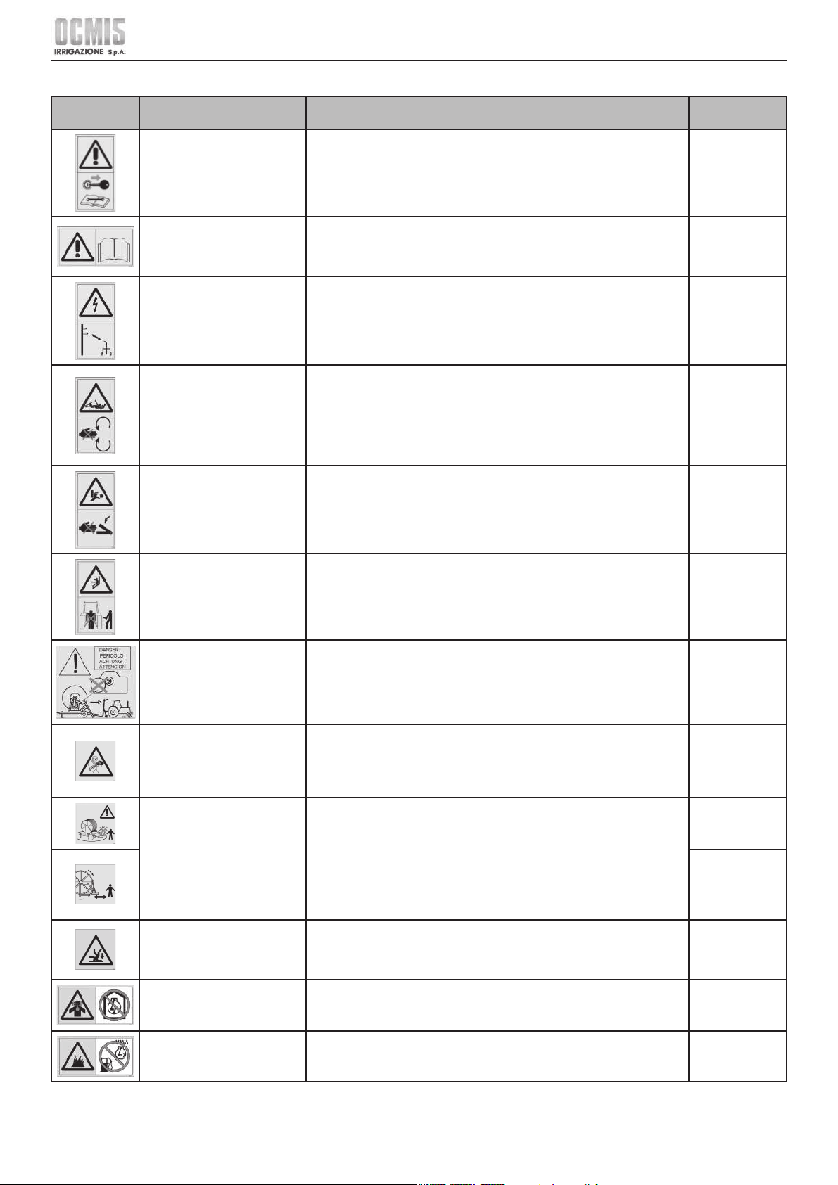
Obligation to stop the machine
before performing maintenance
and/or repair operations on it.
Indicates a mandatory requirement for the maintenance personnel to
read and understand the instruction manual provided before performing
maintenance activities on the machine or its units.
Obligation to stop the machine before performing maintenance operations.
Pay the utmost attention to the signs and areas where this symbol is
displayed.
60201
Obligation to read the
instruction manual before
starting and using the machine.
Indicates a mandatory requirement for the operating personnel in charge
of running the machine or its units to read and understand the instruction
manual provided before performing operating activities on the machine or
its units.
60203-O
Electrocution hazard. Indicates a danger with injury hazard for the personnel in charge/user.
Obligation to keep a safe distance between the hose trolley and the power
lines or substations and not to aim the water jet at power lines.
Pay the utmost attention to the signs and areas where this symbol is
displayed.
CE7/1
Entanglement hazard. Indicates a danger in area/s with moving parts.
It is forbidden to put your hands close to the moving power take off shaft or
to the trolley that places the hose on the reel.
Only use CE certifi ed power take off shafts, with adequate guards and
which are in a good state of repair.
The personnel in charge/user must pay the utmost attention to the signs
and areas displaying this symbol and remain at a safe distance.
60200
Shearing hazard, keep your
hands away.
Indicates a danger with injury hazard, even fatal, for the personnel in
charge/user.
Pay the utmost attention to the signs and areas displaying this symbol and
do not access areas thus signalled unless the area in question has had
supply lines and/or power pre-emptively removed.
60209
Crushing hazard, do not stand
between the machine and the
tractor.
Indicates a danger with injury hazard for the user.
It is mandatory to comply with the safety distances and never to stand
between the tractor and the machine.
Pay the utmost attention to the signs and areas where this symbol is
displayed.
60208
Impact / entanglement hazard.
Moving parts. Do not leave the
handwheel on when unwinding
the hose with the tractor.
Indicates a danger with injury hazard for the personnel in charge/user.
It is forbidden to leave the handwheel on when the irrigation hose is
unwound with the tractor.
Pay the utmost attention to the signs and areas where this symbol is
displayed.
CE8
Danger - pressurised hoses Indicates a danger with injury hazard for the personnel in charge/user.
It is mandatory to wear appropriate clothing such as shoes, overalls, face
protection shields, gloves, etc.
Pay the utmost attention to signals and areas where this symbol is displayed
and keep away from these areas.
60204
Automatic operation machine
with moving parts.
Indicates a danger with injury hazard for the personnel in charge/user.
Do not stand within the operating range of the machine especially during
rotation on the vertical axis.
Do not go near the rear of the machine, where the hose is wound onto the
rotating reel.
Pay the utmost attention to the signs and areas where this symbol is
displayed.
CE45
60202
Slipping and falling hazard. Indicates a danger with injury hazard for the personnel in charge/user.
Prohibition to climb on the machine.
Pay the utmost attention to the signs and areas where this symbol is
displayed.
60215
Carbon monoxide hazard. Caution - the engine releases carbon monoxide, which is a toxic and
poisonous gas.
Do not operate the engine in closed premises.
60214
Fuel. Fuel is extremely fl ammable. Turn off the engine and let it cool before
refuelling.
The same requirement applies before performing any maintenance activity.
60216
7
Ocmis Irrigazione S.p.A. – INSTRUCTION AND WARNING MANUAL – Translation of Original Instructions
MUMR-R1.02 .EN - 31/07/2015
CHAPTER 1 - General information
Symbol Meaning Notes
Code
Manufacturer
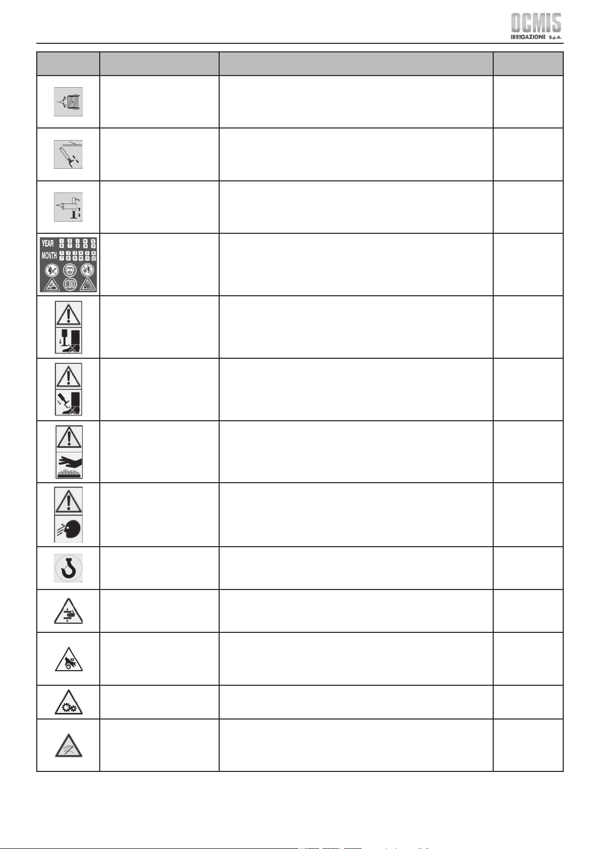
Indicates a hazard connected
to the hydraulic turret rotation
function.
Indicates the function performed by the lever on the distributor.
It is mandatory to keep a safe distance from the machine during turret
rotation.
Pay the utmost attention to the signs and areas where this symbol is
displayed.
CE4
Indicates a hazard connected
to the rear hydraulic anchors
function.
Indicates the function performed by the lever on the distributor.
It is mandatory to keep a safe distance from the anchors, and ensure no
one can come into contact with them.
Pay the utmost attention to the signs and areas where this symbol is
displayed.
CE2
Indicates a hazard connected
to the front hydraulic leg
function.
Indicates the function performed by the lever on the distributor.
It is mandatory to keep a safe distance during the operation of the leg
stabiliser, and ensure no one can come into contact with it.
Pay the utmost attention to the signs and areas where this symbol is
displayed.
CE3
Indicates year and month
of construction with related
warning, danger and prohibition
symbols
Indicates a prohibition for the personnel in charge/user concerning the
battery compartment and requirements to be complied with in handling the
battery.
Pay the utmost attention to the signs and areas where this symbol is
displayed.
See BATTERY
manual
Foot crushing hazard under the
front stabiliser leg.
Indicates a danger with injury hazard for the personnel in charge/user.
It is mandatory to keep a safe distance during the operation of the leg
stabiliser, and ensure no one can come into contact with it.
Pay the utmost attention to the signs and areas where this symbol is
displayed.
60210
Foot crushing hazard under the
rear stabilisers.
Indicates a danger with injury hazard for the personnel in charge/user.
It is mandatory to keep a safe distance during the operation of the rear
stabilisers, and ensure no one can come into contact with them.
Pay the utmost attention to the signs and areas where this symbol is
displayed.
60211
Hazardous temperature Indicates a danger with injury hazard for the personnel in charge/user.
It is mandatory to wear appropriate clothing such as shoes, overalls, high
temperature gloves, etc.
Pay the utmost attention to the signs and areas where this symbol is
displayed.
60212
Hazard of being thrown from
the high pressure water jet
Indicates a danger with injury hazard for the personnel in charge/user.
It is mandatory to wear appropriate clothing such as shoes, overalls, face
protection shields, gloves, etc. and to always stand clear of the water jet
exiting the machine. Pay the utmost attention to signals and areas where
this symbol is displayed and keep away from these areas.
60213
Indicates the position where
the hooks for lifting the machine
need to be inserted
Indicate the hooking points with chains or wire ropes fi tted with hooks.
Indicates a mandatory requirement on the equipment to be used.
Pay attention to these plates and only use permissible lifting/handling
systems using cranes and/or overhead travelling cranes of suitable capacity.
60210
Limb crushing hazard. Indicates a danger with injury hazard for the personnel in charge/user.
Pay the utmost attention to the signs and areas where this symbol is
displayed.
Entanglement hazard. Indicates a danger with injury hazard for the user.
It is mandatory to wear appropriate clothing such as shoes, overalls, gloves,
etc.
Pay the utmost attention to the signs and areas where this symbol is
displayed.
Danger of moving parts. Indicates a danger in area/s with moving parts.
The personnel in charge/user must pay the utmost attention to the signs
and areas displaying this symbol and remain at a safe distance.
Keep hands clear.
Do not touch.
Indicates a danger with injury hazard for the personnel in charge/user.
It is mandatory to wear appropriate clothing such as shoes, overalls, gloves,
etc.
Pay the utmost attention to the signs and areas where this symbol is
displayed.
8
Ocmis Irrigazione S.p.A. – INSTRUCTION AND WARNING MANUAL – Translation of Original Instructions
MUMR-R1.02 .EN - 31/07/2015
CHAPTER 1 - General information
Symbol Meaning Notes
Code
Manufacturer
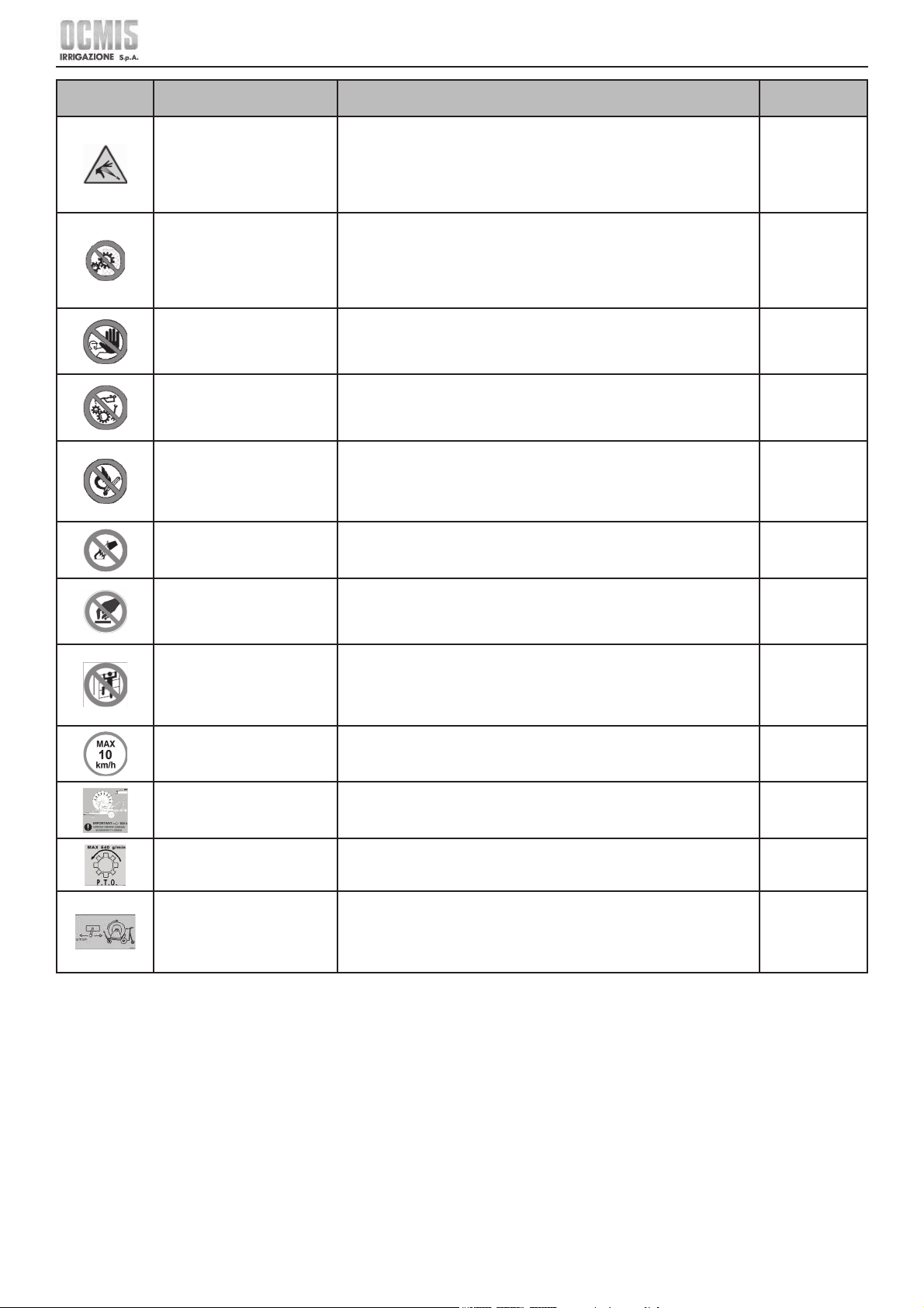
Risk of cutting or violent impact
with high pressure fl uid.
Indicates a hazard with risk of injury, even fatal, to the user, due to impact
with high pressure fl uid.
It is mandatory to wear appropriate clothing such as shield, shoes, overalls,
gloves, etc.
Pay the utmost attention to the signs and areas where this symbol is
displayed.
It is forbidden to remove the
protective casings.
Indicates a prohibition for the personnel in charge/user to remove the
guards installed on the machine/plant.
It is strictly forbidden to operate the machine without the protective casings
it is supplied with.
Pay the utmost attention to the signs and areas where this symbol is
displayed.
Prohibition to approach and go
beyond the barrier/area when
machine is in operation.
Indicates the prohibition for the personnel in charge/user to approach and
go beyond the area where this sign is displayed.
Pay the utmost attention to the signs and areas where this symbol is
displayed.
It is forbidden to lubricate with
parts in motion.
Indicates the prohibition for the personnel in charge/user to lubricate
machine/plant parts with moving parts.
Pay the utmost attention to the signs and areas where this symbol is
displayed.
It is forbidden to smoke
near engines or electrical
or hydraulic control units or
anywhere near the machine.
Indicates the prohibition for the personnel in charge/user to smoke near
engines or electrical control units and in any case in any area where this
sign is displayed.
All prohibitions in force in the country of use of the machine/plant remain
valid, as well as internal facility or plant provisions set out by the employer.
It is forbidden to aim water jets
at electrical equipment.
Indicates a prohibition to use or aim water jets at electrical equipment and
in any case in all areas where this sign is displayed.
Do not touch. Indicates the prohibition for the personnel in charge/user to touch the areas
of the machine where this symbol is displayed.
Pay the utmost attention to the signs and areas where this symbol is
displayed.
It is forbidden to climb on parts
of the machine.
Indicates the prohibition for the personnel in charge/user to climb on the
machine or its parts, including the raingun trolley where this symbol is
displayed.
Pay the utmost attention to the signs and areas where this symbol is
displayed.
60190
Speed limit for machines
without Road Use Approval.
Indicates a prohibition to exceed the set speed for machines without Road
Use Approval.
It is strictly forbidden to exceed the indicated speed limit.
60027
Warning: periodically grease
the teeth of the crown gear
Indicates to grease every 100 hours of work all the teeth of the crown gear
located on one side of the machine.
60105
Warning: rotation direction and
maximum RPMs of PTO shaft
Indicates PTO rotation direction and maximum 540 RPMs.
CE6
Indicates the type of function
performed by the machine in
the two positions of the control
lever
Indicates an operating mode of the control lever in the two permissible
positions:
• with the lever to the left, the functions are STOP, hose UNWINDING or
QUICK WINDING;
• with the lever to the right, the function is OPERATION.
99000015
9
Ocmis Irrigazione S.p.A. – INSTRUCTION AND WARNING MANUAL – Translation of Original Instructions
MUMR-R1.02 .EN - 31/07/2015
CHAPTER 1 - General information
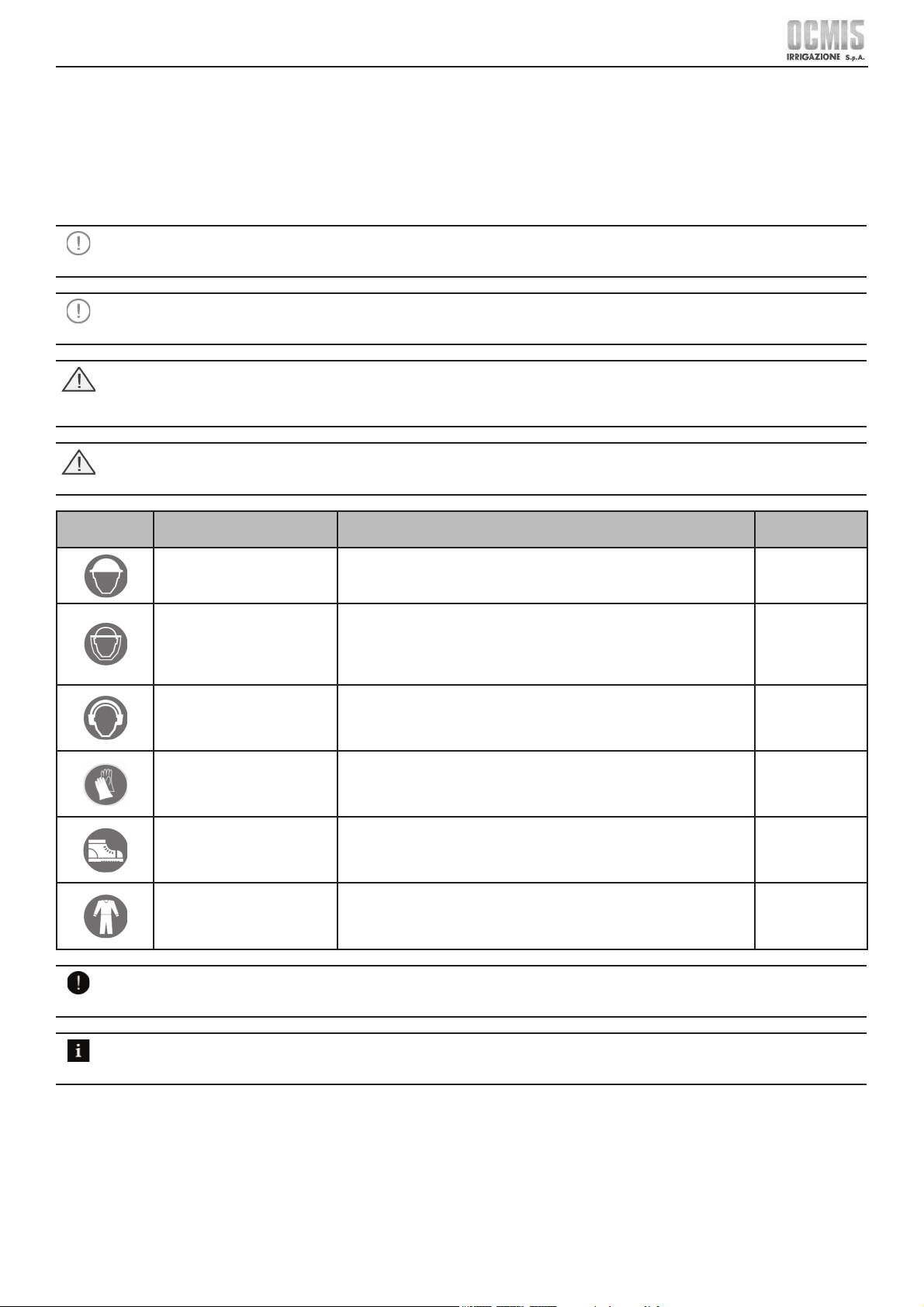
1.9 DESCRIPTION OF PERSONAL PROTECTION EQUIPMENT (PPE)
The personnel in charge of operation, use and maintenance must use the personal protection equipment that allows them to decrease all possible
risks arising from the various permissible activities on the machine, such as:
• head protection helmet.
• safety glasses or face mask to protect against chips, dust or oil jets, or debris resulting from the process.
• masks to protect against any vapours, inhalation, etc. arising from work hazards.
• safety gloves, shoes and boots as needed and according to the type of products used in the process in question.
• ear protectors.
CAUTION
The clothing of whoever operates or performs maintenance on the machine must comply with the essential safety requirements
set forth by EC directives 89/656/EC and 89/868/EC and with the laws in force in the country of installation.
CAUTION
It is the end user's unequivocal responsibility to ensure that the personnel in charge are duly instructed on the residual risks
connected to the process and use the proper PPE, as well as assessing the need for any required integration.
DANGER
During handling and maintenance operations, personnel must wear appropriate work clothing to prevent accidents.
In order to prevent mechanical risks such as entrainment, entrapment and the like, it is forbidden to wear accessories such as
bracelets, watches, scarves, rings or chains during work and maintenance operations.
DANGER
In performing work that might give rise to fl ying splinters or hazardous materials for oneself or other persons operating nearby,
the operator must arrange screens or other appropriate safety devices or obtain them from those responsible.
Symbol Meaning Notes
Code
Manufacturer
Use of the protective helmet is
mandatory.
Indicates a mandatory requirement for maintenance personnel to use the
protective helmet.
PPE to be always used when performing machine maintenance.
Use of protective shield
or protective goggles is
mandatory.
Indicates a mandatory requirement for personnel to use the protective
shield.
PPE to be always used when performing machine maintenance.
Use of protective shield or goggles is mandatory in the event of fl ying
objects or materials hazard.
It is mandatory to protect one's
hearing.
Indicates a mandatory requirement for personnel to use earmuffs or ear
plugs to protect their hearing.
PPE to be used at all times when operating the machine and/or at the
processing site or during maintenance.
It is mandatory to use protective
and insulating gloves.
Indicates a mandatory requirement for the personnel to use protective and
insulating gloves.
PPE to be used at all times when operating the machine and/or at the
processing site or during maintenance.
It is mandatory to use safety
shoes.
Indicates a mandatory requirement for personnel to use protective
footwear.
PPE to be used at all times when operating the machine and/or at the
processing site or during maintenance.
It is mandatory to wear
appropriate work clothing.
Indicates a mandatory requirement for personnel to wear appropriate and
protective work clothing.
PPE to be used at all times when operating the machine and/or at the
processing site or during maintenance.
NOTE
The PPE set out herein must be supplemented by the user according to the processing site (type and materials to be processed,
etc.), to set requirements and according to the provisions in force in the country of use.
SUPPLEMENTARY INFORMATION
The various chapters of this manual contain the detailed description of the “pictograms” and “PPE” specifi cally provided for the
machine supplied. This paragraph only lists and explains the meanings of the “pictograms” and “PPE”.
10
Ocmis Irrigazione S.p.A. – INSTRUCTION AND WARNING MANUAL – Translation of Original Instructions
MUMR-R1.02 .EN - 31/07/2015
CHAPTER 1 - General information
1.10 MANUAL LANGUAGE
The original manual was drawn up in Italian and translated into the language indicated on the manual's cover.
Any translations into additional languages must be done starting from the original instructions.
The Manufacturer is only responsible for the information contained in the Original Instructions; translations into other languages cannot be fully
verifi ed, hence should an inconsistency be found, refer to the text in the original language or contact our Technical Documentation Department.
1.11 MACHINE HANDLING
Handling of the machine is only allowed to authorised personnel, suitably instructed or at least possessing a suffi cient technical knowledge and
experience.
The personnel in charge of machine operation and maintenance must be aware of the fact that knowledge and application of safety regulations is an
integral part of their job.
Specifi cally, it is the User/Customer's unequivocal responsibility:
• To ensure the utilisation site complies with statutory provisions in force in the country of use.
• To check and arrange for the required transit and escape routes and operating and maintenance clearances around the machine.
• Carefully read this manual and the manuals listed in chapter 9.
• Know what guards, safety and emergency stop devices the machine is equipped with, and their location and operation.
DANGER
Unauthorised personnel must not access the machinery's operating area or the control system.
It is forbidden to disengage or partially remove guards and safety devices protecting from hazardous parts.
the same rule applies to signs (warning, danger, prohibition plates, etc.).
It is strictly forbidden to open boards, battery compartments and/or control and power units during operation or immediately
after switching off.
DANGER
The safety guards and devices must be maintained in perfect working order so that they operate correctly. In the event of a fault
or malfunction, they must be immediately repaired or replaced.
DANGER
Unauthorised use of trade components and accessories belonging to the safety guards and devices may cause malfunctions and
lead to hazardous situations for the operating personnel.
NOTE
Most accidents and injuries occurring in workplaces and specifi cally on farms are caused by failure to comply with certain simple
and fundamental rules of prudence and safety. That is why, in most cases, they may be avoided by operating with the necessary
caution and prudence.
In the event of failure to comply with the instructions herein, any possible accident cannot be wholly ruled out with this type of
machine, however well designed and constructed.
A watchful and prudent operator is the best guarantee against accidents.
DANGER
• Incorrect operation and maintenance of the machine may be hazardous and lead to serious injury or death.
• The operator using the machine and the personnel in charge of its maintenance must read this manual in its entirety, before
starting to operate the machine.
• Certain actions concerning machine operation and maintenance may cause severe accidents unless they are undertaken in
the manner described by this manual.
• The procedures and precautions described in this manual only apply to the intended and stated uses for the machine.
• In no case must the machine be used for actions strictly forbidden in this manual.
NOTE
Strict compliance with a single and elementary safety rule is enough to prevent a high number of serious injuries.
That rule is:
Never perform any cleaning, lubrication or maintenance operation while the machine is moving and/or water is pressurised.
1.12 WARRANTY
The warranty applied by the Manufacturer is set out in the contractual documents, to which you should refer.
11
Ocmis Irrigazione S.p.A. – INSTRUCTION AND WARNING MANUAL – Translation of Original Instructions
MUMR-R1.02 .EN - 31/07/2015
CHAPTER 2 - Technical specifi cations and layout
TECHNICAL SPECIFICATIONS AND
LAYOUT
CH. 2
2 TECHNICAL DESCRIPTION OF THE MACHINE
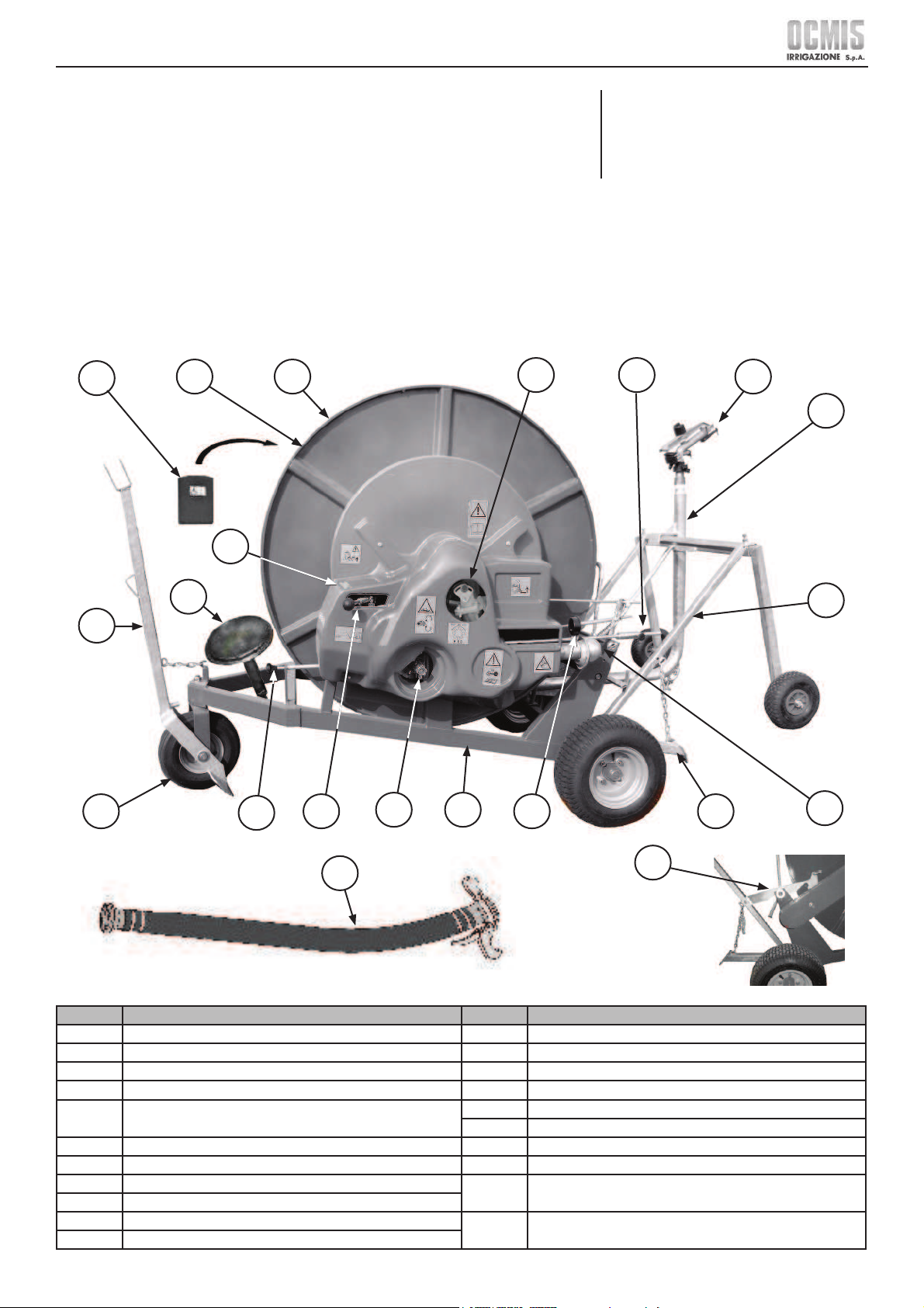
2.1 DESCRIPTION OF MAIN PARTS
The hose reel travelling raingun is a farm machine which is towed for moving it and is used for irrigating fi elds and plots of land after it has been put
in place.
The suitable drawbar “eye” must be used for moving the machine and placing it in the fi eld. The machine consists of the following assemblies/sections,
shown in the Drawing below.
MR-MR/1
Ref. Description Ref. Description
1 Reel 12 Water pressure gauge
2 PE irrigation hose 13 Rear anchors
3 Document holder 14 Water inlet
4 Identifi cation plate 15 Trolley loading frame
5
Handwheel for manual winding
(optional feature)
16 Raingun trolley
17 Irrigator (Raingun)
6 Tow bar 18A By-pass adjustment lever (for MR40-43)
7 Front pivoting wheel 18B By-pass adjustment rod (for MR50#63)
8 Ratchet rod
19
Hooking lever for trolley loading frame
(standard for MR50#63)
9 Turbo-gearbox lever
10 Quick winding power take off
20 Water supply hose
11 Frame
12
3
19
6
4
7
8
9
10 11
13
16
15
5
14
12
17
20
18A 18B
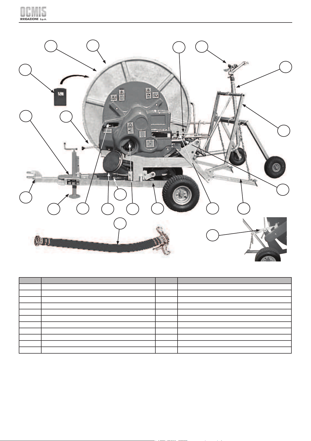
12
Ocmis Irrigazione S.p.A. – INSTRUCTION AND WARNING MANUAL – Translation of Original Instructions
MUMR-R1.02 .EN - 31/07/2015
CHAPTER 2 - Technical specifi cations and layout
MRR
Ref. Description Ref. Description
1 Reel 12 Water pressure gauge
2 PE irrigation hose 13 Rear anchors
3 Document holder 14 Water inlet
4 Identifi cation plate 15 Trolley loading frame
5 Handwheel for manual winding 16 Raingun trolley
6 Tow bar 17 Irrigator (Raingun)
7 Manually operated front stabiliser leg 18 By-pass adjustment rod
8 Ratchet rod 19 Hooking lever for trolley loading frame
9 Turbo-gearbox lever 20 Water supply hose
10 Quick winding power take off 21 Turret rotation locking pin
11 Traveller
1
2
8
3
4
6
7
9
5 10
11 12 13
14
15
16
17
20
19
21
13
18
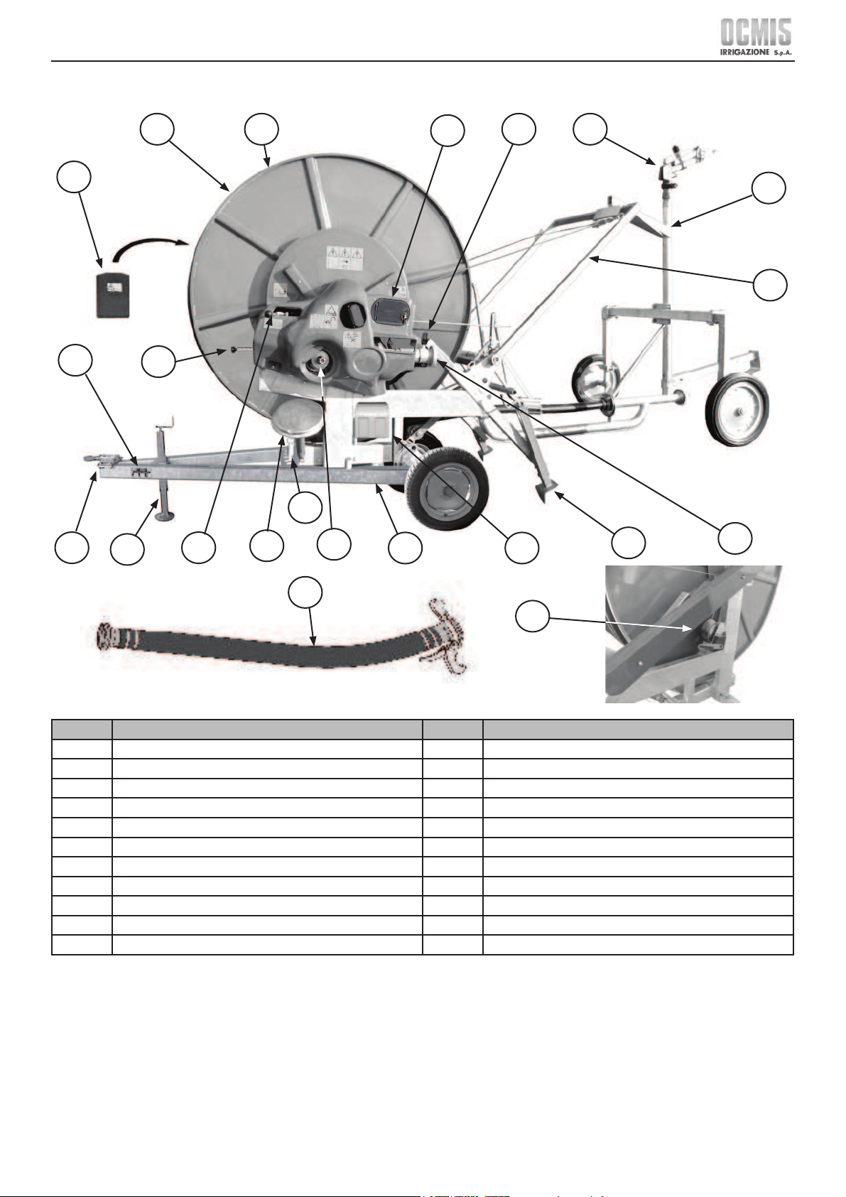
13
Ocmis Irrigazione S.p.A. – INSTRUCTION AND WARNING MANUAL – Translation of Original Instructions
MUMR-R1.02 .EN - 31/07/2015
CHAPTER 2 - Technical specifi cations and layout
R1AT15
Ref. Description Ref. Description
1 Reel 12 Water pressure gauge
2 PE irrigation hose 13 Mechanical rear stabilisers
3 Document holder 14 Water inlet
4 Identifi cation plate 15 Trolley loading frame
5 Handwheel for manual winding 16 Raingun trolley
6 Tow bar 17 Irrigator (Raingun)
7 Manually operated front stabiliser leg 18 Winch for lifting the trolley frame with steel cables
8 Ratchet rod 19 Battery holder + battery
9 Turbo-gearbox lever 20 Water supply hose
10 Quick winding power take off 21 Turret rotation locking pin
11 Traveller 22 Computer (standard AQUA SYSTEM)
12
3
4
8
6
7
9
5
10
11 19
13
14
15
16
17
20
18
21
12
22
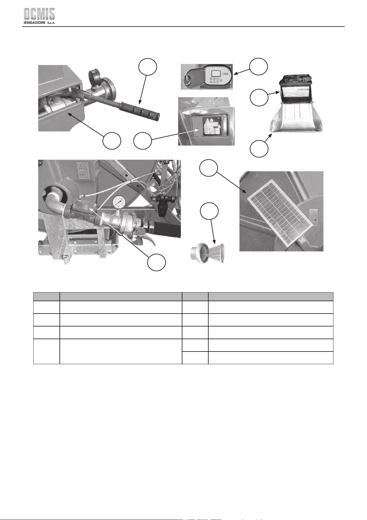
14
Ocmis Irrigazione S.p.A. – INSTRUCTION AND WARNING MANUAL – Translation of Original Instructions
MUMR-R1.02 .EN - 31/07/2015
CHAPTER 2 - Technical specifi cations and layout
2.2 DESCRIPTION OF OPTIONAL PARTS
Below is a description of the optional parts that may be supplied with the machine according to the customer's specifi c requirements.
Ref. Description Ref. Description
23 Inlet valve 27 Electronic metre counter
24 Inlet valve handle 28 Battery
25 Discharge valve 29 Battery holder
26
Computer AQUA SYSTEM (standard for R1AT15 )
( RAIN CONTROL only for R1AT15 )
30 Photovoltaic panel
31 Water inlet fi lter
25
31
30
23
24
27
26
28
29
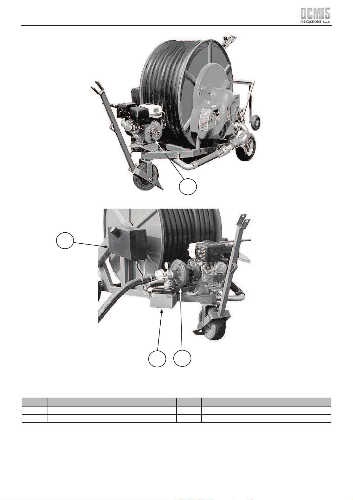
15
Ocmis Irrigazione S.p.A. – INSTRUCTION AND WARNING MANUAL – Translation of Original Instructions
MUMR-R1.02 .EN - 31/07/2015
CHAPTER 2 - Technical specifi cations and layout
Ref. Description Ref. Description
32 Internal combustion engine 34 Pump
33 Fuel tank 35 Battery
33
32
34
35
MR-MR/1
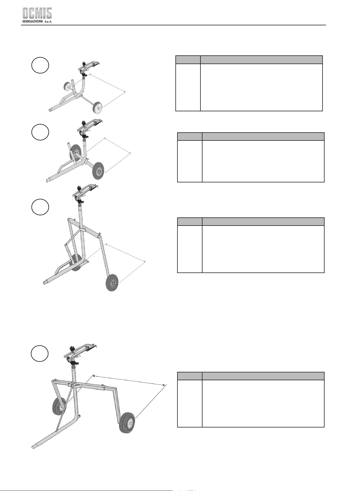
16
Ocmis Irrigazione S.p.A. – INSTRUCTION AND WARNING MANUAL – Translation of Original Instructions
MUMR-R1.02 .EN - 31/07/2015
CHAPTER 2 - Technical specifi cations and layout
2.3 DESCRIPTION OF RAINGUN TROLLEYS
2.3.1 DESCRIPTION OF MAIN PARTS AND WHEEL WIDTH
Ref. Description
36
Raingun trolley
2-WHEEL SKID MR
for hoses Ø 40 - 43 mm
OPENING: 0.92 m
2 Solid tyres code 00449
Ref. Description
37
Raingun trolley
HEAVY 2-WHEEL SKID MR
for hoses Ø 40 - 43 mm
OPENING: 0.88 m
2 Solid tyres code 00436
Ref. Description
38
Raingun trolley
HIGH 2-WHEEL SKID MR
for hoses Ø 40 - 43 mm
MIN OPENING : 1.17 m
MAX OPENING : 1.60 m
2 Solid tyres code 00436
36
37
38
MIN - MAX
OPENING
OPENING
MIN - MAX
Ref. Description
39
Raingun trolley
2-WHEEL SKID MR/1
for hoses Ø 50 – 58 - 63 mm
MIN OPENING : 1.25 m
MAX OPENING : 1.70 m
2 Solid tyres code 00436
39
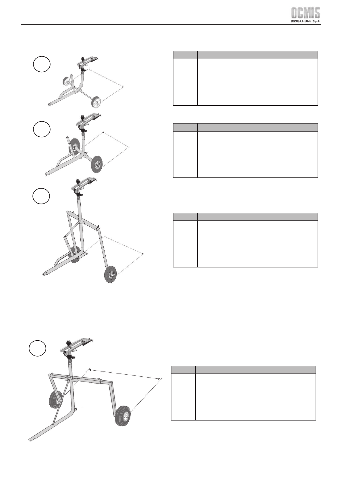
17
Ocmis Irrigazione S.p.A. – INSTRUCTION AND WARNING MANUAL – Translation of Original Instructions
MUMR-R1.02 .EN - 31/07/2015
CHAPTER 2 - Technical specifi cations and layout
Ref. Description
36
Raingun trolley
2-WHEEL SKID MR
for hoses Ø 1.57 - 1.69 in
OPENING: 3.02 ft
2 Solid tyres code 00449
Ref. Description
37
Raingun trolley
HEAVY 2-WHEEL SKID MR
for hoses Ø 1.57 - 1.69 in
OPENING: 2.89 ft
2 Solid tyres code 00436
Ref. Description
38
Raingun trolley
HIGH 2-WHEEL SKID MR
for hoses Ø 1.57 - 1.69 in
MIN OPENING: 3.84 ft
MAX OPENING: 5.25 ft
2 Solid tyres code 00436
36
37
38
MIN - MAX
OPENING
OPENING
Ref. Description
39
Raingun trolley
2-WHEEL SKID MR/1
for hoses Ø 1.96 – 2.28 - 2.48 in
MIN OPENING: 4.10 ft
MAX OPENING: 5.58 ft
2 Solid tyres code 00436
39
MIN - MAX
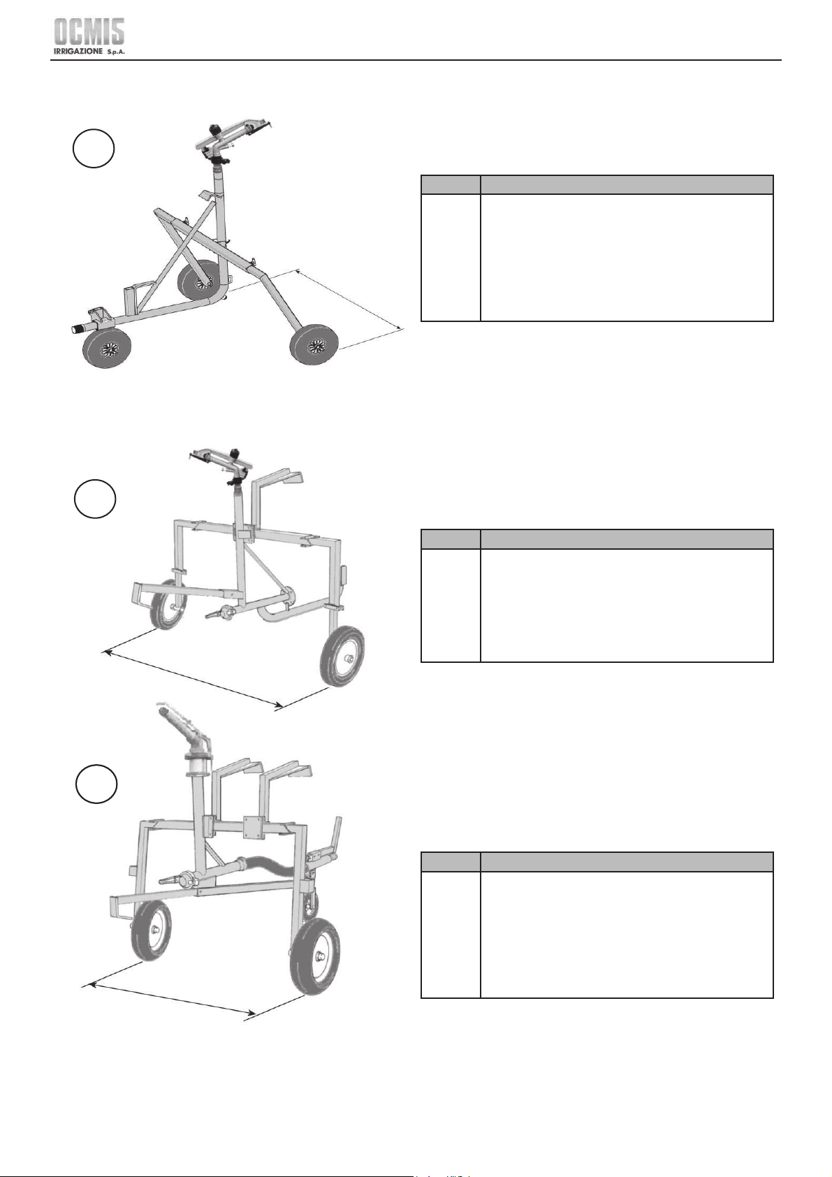
18
Ocmis Irrigazione S.p.A. – INSTRUCTION AND WARNING MANUAL – Translation of Original Instructions
MUMR-R1.02 .EN - 31/07/2015
CHAPTER 2 - Technical specifi cations and layout
Ref. Description
40
Raingun trolley
3 WHEELS MRR
for hoses Ø 50 – 58 - 63 mm
MIN OPENING: 1.15 m
MAX OPENING: 1.60 m
2 Solid tyres code 00437
1 Solid nose wheel code 00437
Ref. Description
41
Raingun trolley
2 SKID WHEELS R1AT15
for hoses Ø 50 – 58 - 63 mm
MIN OPENING: 1.60 m
MAX OPENING: 2.10 m
2 Solid tyres code 00425
Ref. Description
42
Raingun trolley
3 WHEELS R1AT15
for hoses Ø 50 – 58 - 63 mm
MIN OPENING: 1.25 m
MAX OPENING: 1.70 m
2 Solid tyres code 00435
1 Pneumatic wheel code 00405
40
MIN - MAX
41
42
MIN - MAX
MIN - MAX

19
Ocmis Irrigazione S.p.A. – INSTRUCTION AND WARNING MANUAL – Translation of Original Instructions
MUMR-R1.02 .EN - 31/07/2015
CHAPTER 2 - Technical specifi cations and layout
Ref. Description
41
Raingun trolley
2 SKID WHEELS R1AT15
for hoses Ø 1.96 – 2.28 - 2.48 in
MIN OPENING: 5.25 ft
MAX OPENING: 6.89 ft
2 Solid tyres code 00425
Ref. Description
42
Raingun trolley
3 WHEELS R1AT15
for hoses Ø 1.96 – 2.28 - 2.48 in
MIN OPENING: 4.10 ft
MAX OPENING: 5.58 ft
2 Solid tyres code 00435
1 Pneumatic wheel code 00405
40
MIN - MAX
41
42
MIN - MAX
MIN - MAX
Ref. Description
40
Raingun trolley
3 WHEELS MRR
for hoses Ø 1.96 – 2.28 - 2.48 in
MIN OPENING: 3.77 ft
MAX OPENING: 5.25 ft
2 Solid tyres code 00437
1 Solid nose wheel code 00437
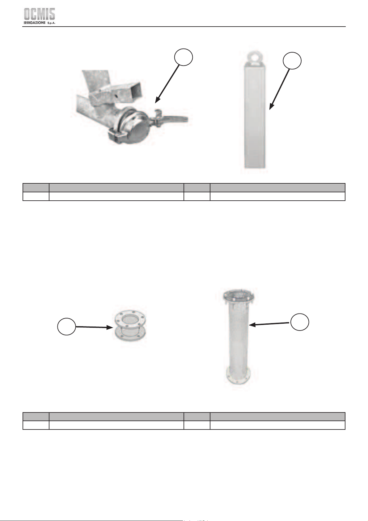
20
Ocmis Irrigazione S.p.A. – INSTRUCTION AND WARNING MANUAL – Translation of Original Instructions
MUMR-R1.02 .EN - 31/07/2015
CHAPTER 2 - Technical specifi cations and layout
2.3.2 DESCRIPTION OF THE MAIN ACCESSORIES
43
44
Ref. Description Ref. Description
43 Discharge cap for trolley 44 Trolley balancing ballast
2.3.3 DESCRIPTION OF OPTIONAL ACCESSORIES
5
Ref. Description Ref. Description
45 Raingun reduction and/or adapter 46 Extension for maize trolley-
45
46
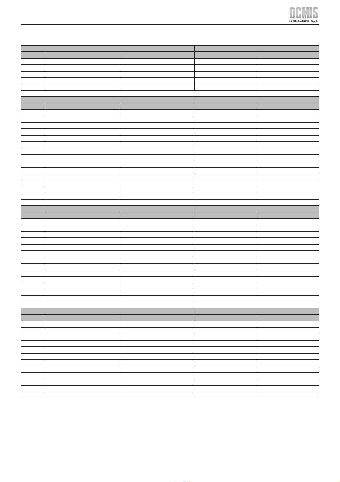
21
Ocmis Irrigazione S.p.A. – INSTRUCTION AND WARNING MANUAL – Translation of Original Instructions
MUMR-R1.02 .EN - 31/07/2015
CHAPTER 2 - Technical specifi cations and layout
2.4 TECHNICAL DATA
2.4.1 MACHINE WEIGHTS BASED ON MODEL
MR with 2 STANDARD 15.6.00X6” WHEELS
Ø hose Hose thickness Hose length Weight without water Weight with water
mm mm m kg kg
40 3.5 110 263 357
40 3.5 130 271 382
43 3.5 100 262 364
43 3.5 120 271 393
MR/1 with 2 STANDARD 16.6.50X8” WHEELS
Ø hose Hose thickness Hose length Weight without water Weight with water
mm mm m kg kg
50 3.7 110 366 523
50 3.7 120 372 543
50 3.7 130 377 562
50 3.7 140 383 582
50 3.7 150 388 602
50 3.7 170 399 641
58 4.2 100 378 571
58 4.2 120 393 625
58 4.2 140 407 678
58 4.2 148 413 699
63 4.5 80 373 556
63 4.5 100 390 619
63 4.5 110 398 650
MRR with 2 STANDARD 20X10.0X8” 2PR WHEELS
Ø hose Hose thickness Hose length Weight without water Weight with water
mm mm m kg kg
50 3.7 120 574 745
50 3.7 150 591 804
50 3.7 170 602 844
50 3.7 180 607 864
50 3.7 200 618 903
50 3.7 230 635 963
58 4.2 120 595 827
58 4.2 150 617 907
58 4.2 160 624 933
58 4.2 170 632 960
58 4.2 200 653 1040
63 4.5 150 635 978
R1AT15 with 2 STANDARD 165/55 R14 WHEELS
Ø hose Hose thickness Hose length Weight without water Weight with water
mm mm m kg kg
50 3.7 150 770 983
50 3.7 250 825 1181
58 4.2 150 796 1086
58 4.2 250 869 1352
63 4.5 120 788 1063
63 4.5 130 797 1095
63 4.5 170 831 1220
63 4.5 180 839 1251
63 4.5 200 856 1314
70 5.2 140 858 1249
70 5.2 150 869 1288
Note: All the weights shown refer to machines having a standard set-up with skid raingun trolley.
22
Ocmis Irrigazione S.p.A. – INSTRUCTION AND WARNING MANUAL – Translation of Original Instructions
MUMR-R1.02 .EN - 31/07/2015
CHAPTER 2 - Technical specifi cations and layout
MR
with 2 STANDARD WHEELS 15.6.00X6”
Ø hose Hose thickness Hose length
Weight without
water
Weight with water
in in ft lbs lbs
1.57 0.14 361 580 787
1.57 0.14 427 597 842
1.69 0.14 328 578 802
1.69 0.14 394 597 866
MR/1
with 2 STANDARD 16.6.50X8” WHEELS
Ø hose Hose thickness Hose length
Weight without
water
Weight with water
in in ft lbs lbs
1.97 0.15 361 807 1,153
1.97 0.15 394 820 1,197
1.97 0.15 427 831 1,239
1.97 0.15 459 844 1,283
1.97 0.15 492 855 1,327
1.97 0.15 558 880 1,413
2.28 0.17 328 833 1,259
2.28 0.17 394 866 1,378
2.28 0.17 459 897 1,495
2.28 0.17 486 911 1,541
2.48 0.18 262 822 1,226
2.48 0.18 328 860 1,365
2.48 0.18 361 877 1,433
MRR
with 2 STANDARD 20X10.0X8” 2PR WHEELS
Ø hose Hose thickness Hose length
Weight without
water
Weight with water
in in ft lbs lbs
1.97 0.15 394 1,265 1,642
1.97 0.15 492 1,303 1,773
1.97 0.15 558 1,327 1,861
1.97 0.15 591 1,338 1,905
1.97 0.15 656 1,362 1,991
1.97 0.15 755 1,400 2,123
2.28 0.17 394 1,312 1,823
2.28 0.17 492 1,360 2,000
2.28 0.17 525 1,376 2,057
2.28 0.17 558 1,393 2,116
2.28 0.17 656 1,440 2,293
2.48 0.18 492 1,400 2,156
R1AT15
with 2 STANDARD 165/55 R14 WHEELS
Ø hose Hose thickness Hose length
Weight without
water
Weight with water
in in ft lbs lbs
1.97 0.15 492 1,698 2,167
1.97 0.15 820 1,819 2,604
2.28 0.17 492 1,755 2,394
2.28 0.17 820 1,916 2,981
2.48 0.18 394 1,737 2,344
2.48 0.18 427 1,757 2,414
2.48 0.18 558 1,832 2,690
2.48 0.18 591 1,850 2,758
2.48 0.18 656 1,887 2,897
2.76 0.20 459 1,892 2,754
2.76 0.20 492 1,916 2,840
Note: All the weights shown refer to machines having a standard set-up with skid raingun trolley.
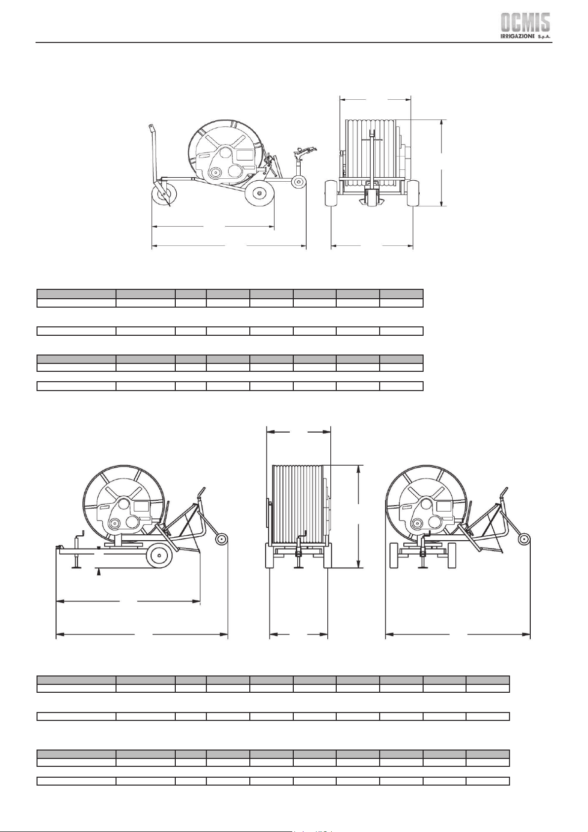
23
Ocmis Irrigazione S.p.A. – INSTRUCTION AND WARNING MANUAL – Translation of Original Instructions
MUMR-R1.02 .EN - 31/07/2015
CHAPTER 2 - Technical specifi cations and layout
2.4.2 DIMENSIONS OF MACHINES WITH 2 WHEELS
MR 2 Wheels um A B C D E
15.6.00 X 6”
STANDARD
cm 107 111 126 195 150
15.6.00 X 6”
STANDARD
in 42.13 43.70 49.60 76.77 59.06
MR/1 2 Wheels um A B C D E
16.6.50 X 8”
STANDARD
cm 112 114 162 270 190
16.6.50 X 8”
STANDARD
in 44.09 44.688 63.78 106.30 74.80
MRR 2 Wheels um A B C D E F G
20 X 10.0 X 8”
STANDARD
cm 109 134 192 330 278 26 250
20 X 10.0 X 8”
STANDARD
in 42.91 52.76 75.59 129.92 109.45 10.23 98.42
R1AT15 2 Wheels um A B C D E F G
165/ 55 R14
STANDARD
cm 149.5 134 220 460 370 26 365
165 / 55 R14
STANDARD
in 58.86 52.76 86.61 181.10 145.67 10.23 143.70
D
E
F
A G
C
B
A
E
D
B
C
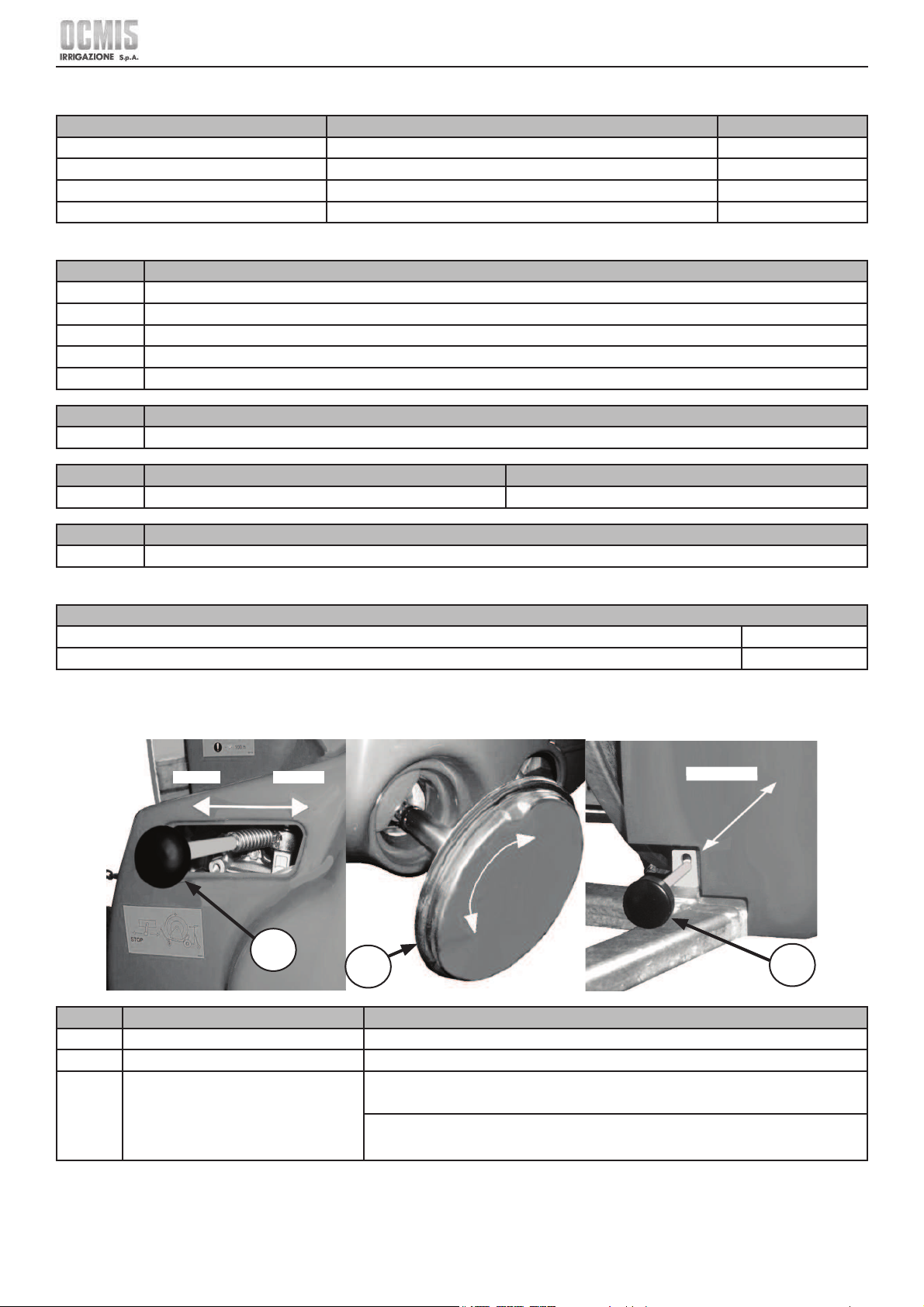
24
Ocmis Irrigazione S.p.A. – INSTRUCTION AND WARNING MANUAL – Translation of Original Instructions
MUMR-R1.02 .EN - 31/07/2015
CHAPTER 2 - Technical specifi cations and layout
2.4.3 WHEEL SIZE AND TECHNICAL SPECIFICATIONS
Code Tyres Infl ation pressure
00367 15.6.00 x 6” 4PR - (≈ Ø 366 - 155 mm / 14.41 x 6.10 in) 2.8 bar / 40.61 psi
00381 16.6.50 x 8” 4PR - (≈ Ø 406 - 165 mm / 15.98 x 6.50 in) 3.0 bar / 43.51 psi
00409 20X10.0X8” 2PR - (≈ Ø 500 - 245 mm / 19.68 - 9.65 in) 1.6 bar / 27.56 psi
00414 165/55 R14- (≈ Ø 630 - 165 mm / 24.80 - 6.49 in) 3.0 bar / 43.51 psi
2.4.4 RAINGUN TROLLEY WHEEL SIZE AND TECHNICAL SPECIFICATIONS
code Solid wheels
00449 SOLID WHEEL - Ø 175 x 45 mm / 6.89 x 2.13 in
00436 SOLID WHEEL 3.00 x 4” - Ø 260 x 85 mm / 10.24 x 3.35in
00437 SOLID WHEEL 4.00 x 4” - Ø 295 x 100 mm / 11.61 x 3.94 in
00425 SOLID WHEEL - Ø 450 x 80 mm / 17.72 x 3.15 in
00435 OVERSIZED SOLID WHEEL - Ø 516 x 140 mm / 20.31 x 21.26 in
code Solid nose wheel for MRR
00437 SOLID WHEEL 4.00 x 4” - Ø 295 x 100 mm / 11.61 x 3.94 in
code Pneumatic Pivoting Wheel Infl ation pressure
00405 13.5.00 x 6” 4PR - (≈ Ø 320 - 122 mm / 12.60 x 4.80 in) 2.8 bar / 40.61 psi
code Iron nose wheel
00493 Ø 320 x 130 mm / 12.59 x 5.12 in
2.4.5 NOISE LEVEL
Noise level
Guaranteed sound power for machines without internal combustion engine L WA 70 dB
Guaranteed sound power for machines with internal combustion engine L WA 104 dB
2.5 DESCRIPTION OF CONTROLS
2.5.1 MECHANICAL CONTROLS ON THE MACHINE
Ref. Description Function
47 Gearbox engage lever It allows the reel rotation gearbox to be set to idle or gear.
48 Power take off handwheel It allows the reel rotation to be manually actuated.
49 Ratchet lever
When the lever rod is pulled outwards (RELEASE), the reel is free to rotate in both
directions.
When the lever rod is pushed inwards (HITCHING), the reel can only rotate in one direction
(that for winding the hose).
47
48
49
HITCHING
STOP WORK
 Loading...