

Ochsner GMLW, GMLW 9, GMLW 14, GMLW 19, GMLW 25 Installation And Operating Instructions Manual
...
Installation and Operating Instructions
GMLW
Heat Pump
Heating/Cooling/Hot Water

Contents:
Installation and Operating Instructions Heat
Pump ................................................................... 2
1 Notes on the documentation .................. 4
2 Safety instructions ................................. 4
2.1 CE Labelling ................................................... 5
3 Appliance description ............................. 5
3.1 Function ......................................................... 5
3.2 Heat Pumps GMLW ....................................... 5
3.3 Guarantee ...................................................... 5
4 Installation ............................................. 6
4.1 Delivery .......................................................... 6
4.2 Transport ........................................................ 7
4.3 Installation location ......................................... 7
4.3.1 Installation of split outdoor unit ....................... 7
4.4 Connecting the heating system ...................... 8
4.4.1 Cooling operation ........................................... 9
4.5 Heat source connection .................................. 9
4.5.1 Wall conduit .................................................... 9
4.5.2 Refrigerant pipework ...................................... 9
4.5.3 Leak check ..................................................... 9
4.5.4 Insulation ........................................................ 9
4.6 Electrical connection .................................... 10
4.6.1 Supply voltage to heat pump ........................ 10
4.6.2 Evaporator wiring ......................................... 11
4.6.3 Cable cross sections .................................... 11
4.6.4 Sensor wiring ................................................ 12
4.6.5 Pumps, motors 230 VAC .............................. 12
4.7 Utility control contact .................................... 12
4.7.1 Switch off via tariff relay:............................... 13
4.7.2 Switch off via ripple control ........................... 13
5 Commissioning ..................................... 13
5.1 Required on-site personnel: ......................... 13
5.2 Check list for commissioning ........................ 14
6 Operating the system ........................... 14
6.1 Safety functions ............................................ 14
6.2 Running costs............................................... 14
7 Maintenance ......................................... 15
7.1 Service work ................................................. 15
7.2 Service and Maintenance ............................. 15
7.3 Trouble shooting ........................................... 16
ANNEX ............................................................... 18
Technical Data GMLW ............................................... 19
Technical Data GMLW plus ........................................ 20
Evaporator connection pipework ................................. 21
Dimensions sheet ....................................................... 22
Operation data MLLENIUM evaporator ..................... 23
Declaration of conformity ............................................ 24
Installation and Operating Instructions Heat Pump
BA_GMLW OTE bis V3.4 SHORT_EN_20090408_V1 Page 2 of 25

BA_GMLW OTE bis V3.4 SHORT_EN_20090408_V1 Page 3 of 25
1 Notes on the documentation
The following pointers are valid for the whole of
the documentation.
Storage:
This instruction Manual must be kept within
easy access close to the heat pump.
Symbols:
The precautionary pointers below will be used
in this document..
Pointer which, if not heeded, can mean danger
to life and limb, and can also lead to material
damage. These pointers must be heeded without fail.
Pointer which, if not heeded, can lead to an
appliance malfunction and to material damage
(to system components, building, ...). These
pointers must be heeded.
Tips which are intended to aid the job in hand,
or mean additional information for the user.
WARNING
CAUTION
POINTER
2 Safety instructions
Read this manual carefully before you begin to
commission/adjust the heat pump!
Converting or altering the appliance is not allowed. Work on the
appliance (repairs, alterations) may
only be carried out by the manufacturer or by a specialist authorised
by the manufacturer.
All circuit breakers in the heating
system are to be turned off before
any work is carried out on the
terminal strips or electrical connections (wiring). The heating
system comprises the control, the
additional modules and the components connected to the control
(energy generator, pumps, nonself-resetting safety thermostat,
etc.).
Contact with the terminal strips,
wires connected to them, or nonconnected wires by persons or by
means of electrically conductive
materials is prohibited, as the
terminal strips could be live (danger of contact with live circuit).
The control, additional modules,
terminal strips and control wiring
may also be being supplied with
live voltage by means of external
switching (non-self-resetting
safety equipment, etc) when the
control is not connected, or no
line voltage is on the control
The commissioning as well as the
maintenance of the appliances may
only be carried out by personnel
which are authorised by OCHSNER.
The installation of the appliances
and their electrical wiring may only
be carried out by a specialist according to local regulations and codes of
practice.
BA_GMLW OTE bis V3.4 SHORT_EN_20090408_V1 Page 4 of 25
Safety functions for the heat pump
may be activated with the control.
As the control is, however, not certified as a safety appliance, safety
mechanisms against failure of, or
damage to the heat pump must adhere to local safety regulations (e.g.
through supplementary external
switching of the safety appliances
used)..
If upgrades/updates to the control
software are carried out, all parametered functions of the heat pump are
to be controlled once again
2.1 CE Labelling
The product you have purchased conforms to
the technical regulations valid at the time of
manufacture, and is CE-conform.
3 Appliance description
3.1 Function
The heat pump converts low-temperature
warmth (for instance, the heat in the soil) into
warmth of a higher temperature (water for heating).
The heat pump extracts from the ambient:
• Soil
• Ground water
• Air
the solar energy stored therein and yields this,
plus the driving energy (electricity) to the heating and hot water circuits in the form of heat.
The system consists of separate circuits which
are connected by means of heat exchangers.
3.2 Heat Pumps GMLW
Heat pumps of the type GMLW are split appliances, where the compressor unit is installed
inside, and the evaporator outside the building.
The compressor unit is suitable for
indoor-installation
door installation.
The heat extraction (from the heat source circuit) takes place usually from the ambient air by
means of a finned-tube heat exchanger.
The GMLW heat pumps function at low temperatures in bivalent-parallel operation. The
heat pump can, however, be combined at any
time with a further heat generating system.
and NOT for out-
3.3 Guarantee
All OCHSNER heat pumps carry a guarantee of
24 months, if the installation and operating instructions are adhered to and the system data
sheet is filled out and stored correctly.
The concept and design of the system is to be
carried out according to current Ochsner –
guidelines and the valid technical regulations.
For flat laying for the heat source ground, the
responsibility for the design of the extraction
area lies with the system planner, taking the
local conditions on site into account.
No guarantee will be given for any defects to
the heat pump which are caused by the heat
source system, the heating system itself, faulty
adjustment of the control and regulation elements or by elementary occurrences (lightning,
flood damage,......)
BA_GMLW OTE bis V3.4 SHORT_EN_20090408_V1 Page 5 of 25
The heat pump is to be commissioned by OCHSNER factory customer service engineers. The correct construction and function of
the heating system, the heat
source and the electrical installation is the be ensured by the installer. Otherwise, no guarantee
or warranty claims will be recognised.
The electrical heating rods and circulation
pumps carry a guarantee period of 12 months.
Parts subject to wear and tear such as protective anodes, filters, signal lamps etc. are excluded from guarantee and warranty claims.
Increased effort due to appliances that are incorrectly located or mounted shall be invoiced
with the guarantee work.
Read this instruction manual carefully before you start commissioning the heat pump!
4 Installation
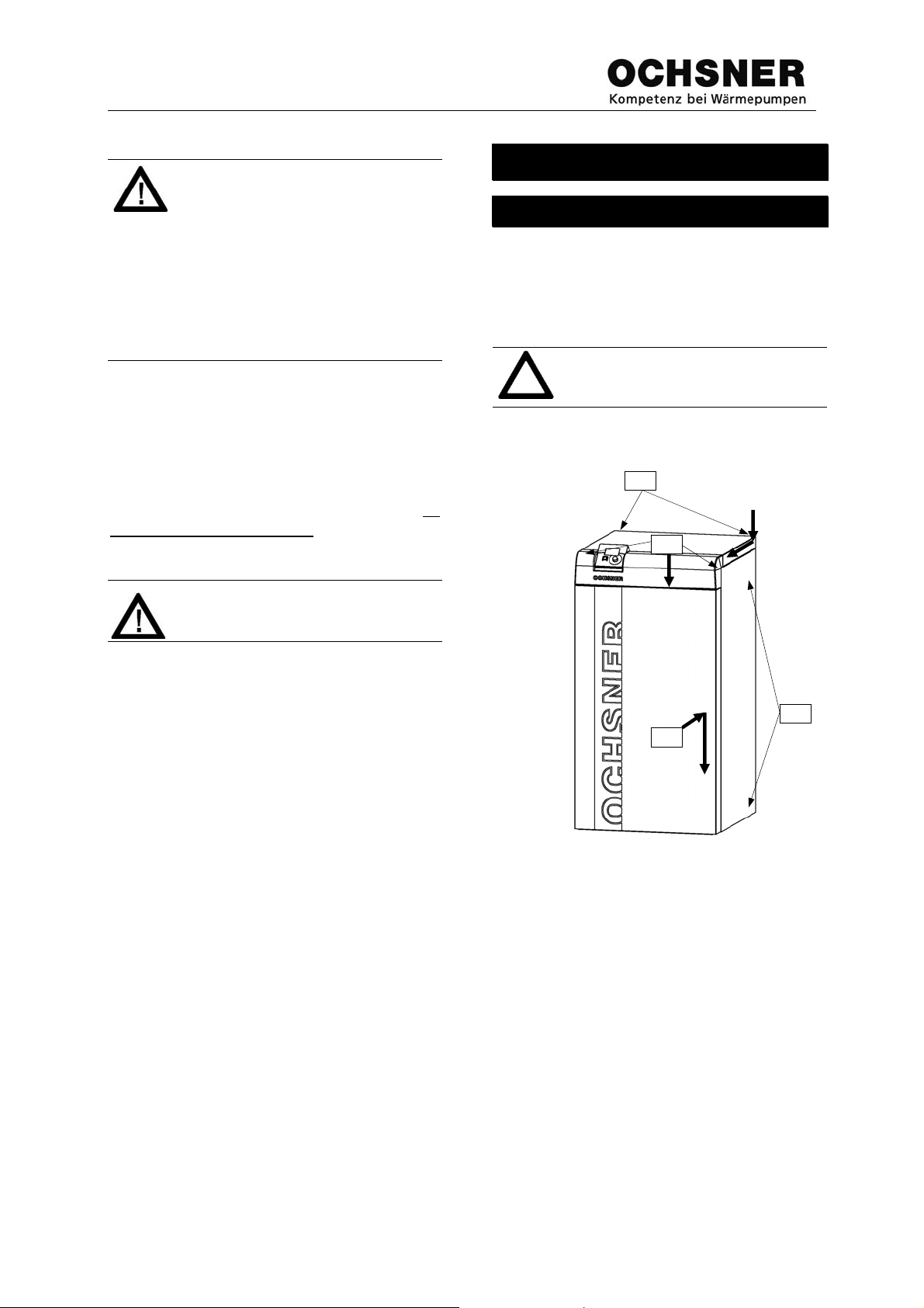
4.1 Delivery
The heat pump is delivered on a non-returnable
palette and pack in cling-film. The cladding is
supplied in the heat pump packaging.
ARA License Nr. 7910
Any transport damage must be immediately reported upon delivery!
The complete cladding must only be fitted after
the heat pump has been entirely connected up.
4
3
1
2
Fig. 1: Casing
1. Mount the left and right hand side panels to
the base frame using the Velcro fasteners.
2. Mount the front panel on to the lugs on the
side panels.
3. Slide the plastic cover into the slots provided
on the front panel and screw to the side
panels using the 2 screws provided.
4. Position the top panel on the side panels,
slide it towards the plastic cover until it slots
home. Screw the top panel to the rear panel
using the 2 screws provided.
BA_GMLW OTE bis V3.4 SHORT_EN_20090408_V1 Page 6 of 25

4.2 Transport
The heat pump is to be transported and stored
in a packaged condition. Careful transport at an
angle of 45° is allowed over short distances.
Ambient temperatures of –20°C to +45°C are
allowed both for transport and storage. The
standard packaging affords no protection
against weather and sea-water.
Transport damage can only be recognised if
this is made known to the driver of the delivery
vehicle during unloading.
4.3 Installation location
The GMLW heat pump can be installed in any
and frost free room.
dry
The installation must
face. The location of the appliance is to be selected such that operation and maintenance
are possible at any time.
(Clearance from the rear of the heat pump to
the wall - min. 50 cm, clearance from the side
of the heat pump to the wall - 30 cm, clearance
from the front of the heat pump to the wall - 70
cm).
The heat pump must
from the floor.
Reverberant rooms can lead to increased noise
sensitivity. A possible noise transfer to adjoining rooms cannot be ruled out and must be
considered during the design.
4.3.1 Installation of split outdoor unit
The installation of the split outdoor unit
rator) is only permissible in the open air and is
to be carried out in such a way that the air-flow
is not hindered on any side.
take place on a level sur-
be decoupled acoustically
(evapo-
A maximum of one side may face a wall. A
minimum clearance of 1m must be ensured.
min. 1 m
Fig. 2: Minimum clearance to a wall
Evaporator
A minimum of 3m clearance above the unit is to
be ensured. Installing the unit in a hollow is not
permitted.
min. 3 m
Evaporator
Fig. 3: Minimum clearance to a ceiling
The distance from the heat pump to the evaporator is usually up to 10m (horizontal). The
maximum permissible difference in height (top
edge of evaporator) is 7m. Larger distances are
to be agreed with the factory in advance.
The following points are to be heeded w hen
installing the evaporator:
• avoid
installing on hard floors which could
transmit vibration
• installing between two walls could lead to an
increase in noise level
Pointer for the installation:
The higher the performance rating of
the heat pump, the louder the noise
made by the compressor.
BA_GMLW OTE bis V3.4 SHORT_EN_20090408_V1 Page 7 of 25
• avoid
• plants and vegetated surfaces can reduce
• in closed rooms, the noise level is depend-
• a frost-protected drainage is to be con-
installing the evaporator alongside
bedrooms
the noise level
ent on the volume of the room and its re-
verberation time.
structed in order to drain off the condensate
accruing. In order to guarantee this, it is
usual to make a collection sump (not supplied) below the evaporator (see Fig. 4) If it
is not possible to make a collection sump
with drainage, a gravel bed is to be made
under the evaporator, In winter ice can form
in the drainage area..
If the condensate drainage is not
executed as recommended, ice
could build up of the surfaces around
the evaporator!
4.4 Connecting the heating system
The heat pump’s hydraulic connection made only be carried out by a
specialist according to local regulations!
All heat pump connections are to be carried out
in a flexible fashion. Acoustic bridges are to be
avoided when installing the pipework. The sizing of the pipe network as well as the selection
of the circulation pump depend upon the heating system in place.
Make sure the following design fundamentals are considered:
The rate of flow in the pipe network
must not exceed 0,8 m/s
(noise/resistance).
In order to ensure a comfortable and
disturbance-free operation, a temperature difference of 5K between
the heating system flow and return is
to be maintained.
When designing the heating system
circulation pump/buffer charge
pump, take the internal pressure difference in the heat pump condenser
into account (see technical data)!
Integrated heating circulation pumps
are designed as buffer charge
pumps (technical data – see annexe). The rate of flow in the pipe
network must not exceed 0,8 m/s
(noise/resistance).
For air/water heat pumps the installation of a
suitably sized decoupling tank (separation tank,
buffer tank) absolutely necessary in order to be
able to provide the necessary energy to be able
to defrost. A manual bleeding valve must be
installed at the highest point in the pipework.
.
If this is not done, there is a danger that the
heat pump will not reach the declared catalogue rating and under certain conditions will be
shut off by means of the high-pressure
switch,Æ ERROR report (see operation instructions OTE).
It must be ensured that no foreign bodies can
get into the pipework (dust, dirt, etc.).
A sieve filter
pipework to the heat pump in order to trap any
dirt. Make sure that the dirt collector
clean for maintenance purposes.
A clogged filter will substantially effect the heat
dissipation and can lead to switch-off by the
high-pressure safety mechanism!
Valves and thermometers
both the flow and return pipework, so that the
heat pump water flow rate and the running conditions can be continuously monitored.
A drain pipe
in the pipework so that the system can be
drained.
The heating system pipework is to be sized
according to the technical data of the heat
pump. Sample hydraulic standard schematics
can be found in Annex A.
can be inserted into the return
is easy to
are to be installed in
is to be installed at the lowest point
BA_GMLW OTE bis V3.4 SHORT_EN_20090408_V1 Page 8 of 25

4.4.1 Cooling operation
For cooling operation, all system components
(pipework, fittings) must be insulated against
condensate forming by means od suitable insulating materials. This holds especially for the
flow pipework from the heat pump to the buffer
tank/distributor.
4.5 Heat source connection
4.5.1 Wall conduit
Conduits through external walls are to be executed with lined pipework. These are to be laid
with a slight slope
This is the only way to guarantee that condensate/rain water gathering can be properly disposed of through the house drainage system,
and no dampness can get into the brickwork. It
is also very important that the feed pipe on the
outside of the building is surrounded by gravel
and is bevelled from the top to the bottom
from inside to out!
Fig. 4: Wall conduit into free air
Fig. 5: Wall conduct into ground
Fig. 6: Foundation
This hinders the water from entering the building in the event of heavy rainfall. After placement, the pipe should be sealed with foam or if
necessary a special sealing compound.
4.5.2 Refrigerant pipework
The refrigerant pipework should always be positioned to the side of the heat pump (left or
right). Connections to rear should only be carried out in exceptional cases, as the connection
is made considerably more difficult!
4.5.3 Leak check
The leak check is to be performed and documented by OCHSNER Customer Service during the commissioning process.
4.5.4 Insulation
All exposed refrigeration lines are to be well
insulated to prevent build-up of condensation
and thermal losses.
Insulation installed underground
must be a closed-pore material. The
insulation properties of the insulation
will otherwise be negatively influenced
BA_GMLW OTE bis V3.4 SHORT_EN_20090408_V1 Page 9 of 25

4.6 Electrical connection
The regulations of the energy utility and the relevant EN-standards
are to be adhered to without fail.
The values indicated in the Appendix for fuseprotection are given solely as reference values.
The implementation of proper safety measures
is the sole responsibility of the electrician connecting the heat pump. In cases of system
damage occurring due to falsely installed safety
devices, OCHNSER provides no guarantee!
4.6.1 Supply voltage to heat pump
The protection for the main electrical circuit is to
be provided by a three pole circuit breaker
which, in case of failure, shuts off all poles
(amperage found in Appendix, Technical Data).
The supply cable must also be protected
against overload and short-outs.
The control circuit should also employ an allpole shut-off circuit breaker. The main and
control circuits must be separate circuits.
.
Control voltage X3
supply X1,X2
Fig. 7:El. connection to heat pump
We recommend that the control voltage and the
main supply have their own FI switch so that, if
there is a short-circuit in the house installation,
the heating system remains in operation.
BA_GMLW OTE bis V3.4 SHORT_EN_20090408_V1 Page 10 of 25

A
Due to the fact that the Scroll-compressors are
3-phase models, they will run in one or the
other direction, depending upon how the terminal L1, L2 and L3 are connected. To check for
correct connection, test whether, when switching on, the pressure on the suction side falls,
and that on the high-pressure side increases.
If the compressor is running in the wrong direction, the pressure on the suction side will increase, the noise level can also be higher than
if the compression is running in the right direction and the motor draws much less current
than stated in the technical data.
All 3-phase motors (compressors,
pumps, fans) MUST be connected to
a RIGHT-HAND ROTARY FIELD
.
Longer continuous operation in the
wrong direction will lead to damage.
OCHSNER takes no liability for this.
Connection work which entails
opening the connection boxes is
to be carried out by an authorised
contracting company, due to the
fact that current-carrying components can endanger life!
4.6.2 Evaporator wiring
The motors and sensors on the evaporator are
supplied from the indoor unit. For this, the following cables must be run from the indoor unit
to the evaporator:
Motors/Sensors Cable
3-phase supply to fan, incl.
signal contact, winding protec-
7 x 1.5
tion
De-ice sensor (TQA, TQE)
4 x 0.75
Electronic expansion valve 4 x 0.75
1
Rotation speed control for fan
2 x 0.75
If a delta-connection is necessary for operation
for technical reasons, special attention must be
paid to the operating currents and particularly to
setting of the motor-protection relays.
Power for a back-up electrical heating element
is to be provided using a separate external
power supply limiter.
4.6.3 Cable cross sections
Commercially available cables are to be used
to wire up actuators and sensors. Following
guidelines are to be heeded.
Position
min. Xsection
Supply cables 230V~: (Pumps,
valve motors)
lways size connecting cables
1.5 mm²
according to local conditions.
Sensor cables: (external sensor,
etc.) Sensor cables must always be
run separately (min. 20 cm) from
230V/400V cables.
0.75 mm²
The max. cable length must not
exceed 50 m.
Bus cables: (Room remote controls, auxiliary modules) must always be run separately (min. 20
cm) from 230V/400V cables. Above
1.0 mm²
50 m cable length, choose 1.5 mm².
The max. cable length must not
exceed 200 m.
Table. 2: Chart cable sizing
Table. 1: List of cables to evaporator
All cables/wiring must be suitable for laying
outdoors and must laid so that they are UVprotected.
1
Only for version with rotational speed control
BA_GMLW OTE bis V3.4 SHORT_EN_20090408_V1 Page 11 of 25

4.6.4 Sensor wiring
De-icing sensors:
2 de-icing sensors (TQA, TQE) are to be installed in the fin-packet of the evaporator. (See
the wiring diagram for the exact positioning of
the sensors) For this, a 4-pole cable is to be run
from the indoor unit to the evaporator. The sensors are then connected together with the 4pole cable in a terminal box which is protected
against moisture (not supplied with heat pump).
The external sensor
(TA) of the control system
is to be installed at approximately 2.5 m height
on the outer side of the building wall (North or
West side). Care must be taken that the thermometer is not exposed to direct solar radiation
or wind; as such placement influences the operational characteristics of the control system.
The heat generator sensor
(TPO) is normally
included with the heat pump at delivery. If a
buffer storage tank or a low loss header is to be
implemented, the sensor is to be mounted internally in the storage device. Placement
should occur in the top
third of the tank. If there
is no low loss header, the heat generator sensor (TPO) will not be installed. See separate
Instruction „Wiring diagram“
The hot water sensor
(TB) is included with the
heat pump at delivery. Placement should occur
in the bottom third, to max. the middle of the
tank. OCHSNER hot water tanks have suitable
sleeve fittings for this installation.
Should a mixing circuit be installed additionally
to the heating circuit, then the mixing circuit
sensor (TMK) is included in the delivery along
with strapping and heat conducting paste. The
sensor is to be installed directly after the mixing
circuit pump.
Do not expose the sensor terminals
to a voltage > 10 V. This may damage or destroy the control.
4.6.5 Pumps, motors 230 VAC
Pumps (heating circuit pumps, water charging
pumps) as well as motors (mixing valves, etc.)
are to be wired directly to the control.
Warning: A test-run may only be
undertaken on a fully-prepared system that is ready for commissioning!
(Hydraulically connected, correct
compressor rotation ensured).
4.7 Utility control contact
In the case of tariff switching (interrupted power
supply) the heat pump will be temporarily
switched off by the utility. A control input (bridge
on terminal EVU, terminal strip X3) is present in
the control. If the tariff switching takes place in
the meter (Night Tariff), the EVU contact must
not be activated.
Fig. 8: Tariff switching contact on terminal X3
BA_GMLW OTE bis V3.4 SHORT_EN_20090408_V1 Page 12 of 25

4.7.1 Switch off via tariff relay:
For switching by means of a tariff relay (sealed
by the utility on site) the 3-phase power supply
to the heat pump is switched off. The heat
pump signal contact must
be executed via the
auxiliary contact on the tariff relay.
4.7.2 Switch off via ripple control
For switching by means of a ripple control receiver (open contact), the heat pump will NOT
be separated from the 3-phase supply.
5 Commissioning
Commissioning requests are to be made to
OCHSNER Customer Service. Fixed commissioning appointments should be made two
weeks in advance.
To undergo the commissioning process, the
following work should be complete:
- The heating and hot-water systems must
be completely installed, filled, bled, and hydraulically adjusted.
- - The electric connection from the main
circuit 3x400V/50Hz, (control circuit
230V/50Hz) and other electrical installations on the building site are complete.
Confirmation of proper field rotation, no
provisional modifications!
Details: see check list supplied in packaging!
Work to be completed by OCHSNER:
- Installation and connection of refrigerant
lines (except collector installation)
- Leak check on refrigeration lines
- Evacuation of the refrigerant lines
- Insulation of the refrigerant lines (only in the
internal area of the system)
- Filling of the system with the proper amount
of refrigerant
- Setting of safety devices
- Inspection of the operation cycle
- Preparation of a commissioning protocol
- Setting of control system for basic opera-
tion
- System orientation, explanation for operator
(if present at commissioning)
5.1 Required on-site personnel:
Electrician, installer and future caretaker/operator MUST
orientation.
Other necessary work performed, such as
bleeding the piping network of air, electrical
wiring, etc., that do not fall within the realm of
the Ochsner firm’s duties will be invoiced separately.
BA_GMLW OTE bis V3.4 SHORT_EN_20090408_V1 Page 13 of 25
be present for the system

adjustment
ob
5.2 Check list for commissioning
Adhere to the following sequence:
1) Check heating system circuit: Systempressure, expansion vessel function,
bleeding valves, quantity adjustment
2) Check whether all non-return valves
are open
3) Check power supplies and circuit
breakers
4) Check refrigerant circuit
5) Check the electrical connections to the
system components, including all required safety equipment, according to
the wiring diagram.
6) Switch on 3-phase supply to the heat
pump.
7) Control 3-phase supply and right-hand
rotary field
8) Switch on control voltage supply
9) Configure the system by means of the
commissioning (IBN) assistant
10) Store the sensor configuration
11) Relay test on the output terminals
12) Adjust the system according to user requirements and document these settings
13) Hand over system to operator
6 Operating the system
The heat pump operation takes place by means
of the basic operating panel. This is easily accessible in a plastic housing mounted on the
heat pump.
The user has 2 knobs and a lit display at his
disposal (Fig. 9)
Display
ESC-knob
Fig. 9:Basic control panel (Master remote control)
The heat pump has no separate
OFF switch. In emergency the system MUST
be switched off by means
of the specified circuit breakers.
The circuit breakers MUST
reachable as to ensure a switching
off at any time
kn
be so
6.1 Safety functions
Following safety features are implemented from
both Hard- and Software:
- Electric control and safety devices for the
compressor
- High pressure safety pressostat
- Start delay to avoid compressor chopping.
- Frost protection function
6.2 Running costs
Pointer:
For optimum heat pump operation,
the lowest possible flow temperature
to the heating circuit should set.
BA_GMLW OTE bis V3.4 SHORT_EN_20090408_V1 Page 14 of 25

An increase of the room temperature
by 1°C means a 5-7% increase in
energy consumption.
Generally, higher operation costs can be expected in the first heating season, depending
upon the residual moisture (up to 50%) in the
building materials
7 Maintenance
7.1 Service work
The heat pump operates maintenance free. It
must, however, be ensured that:
- the evaporator is free from leaves and twigs
or any other foreign bodies,
- the condensation can drain off,
- the heating circuit contains enough water
Pointer:
On request, OCHSNER can offer a
maintenance contract. If interested,
please contact our customer service
department.
7.2 Service and Maintenance
The following services are to be carried out by
our customer service:
- Control of the refrigeration cycle
- Testing and repair (re-working) of electrical
connections
- Testing of safety devices (Pressostats,
thermostats
- Inspection of switch contacts
- Commissioning protocol
- Service and maintenance log entries
- Review of control parameters
-
BA_GMLW OTE bis V3.4 SHORT_EN_20090408_V1 Page 15 of 25

7.3 Trouble shooting
Should a defect or problem arise, despite the selection of parts of highest quality and the painstaking
care put into production, please notify your contracting partner or the OCHSNER customer service department with the heat pump model and product number at the following numbers.
Customer service Austria: Tel.: 0043(0)504245 -14
E-Mail: kundendienst@ochsner.at
Customer service Germany: Tel.: 0049(0)3628 58 108 - 0
E-Mail: kundendienst@ochsner.de
The heat pump model and product number can be found on the heat pump rating plate which is located
on the rear of the unit.
BA_GMLW OTE bis V3.4 SHORT_EN_20090408_V1 Page 16 of 25

Error / Warning Possible Cause Recommended Action
2. Energy provider error - High
Pressure (ER 36)
One or more circulation pumps not
see also Pos. 5.
Air in heating circuit Bleed heating circuit
3-way valve defect Replace
Return-valve does not open Loosen, replace
For external hot-water heating option:
-Heat exchanger too small Enlarge heat exchanger
-Heat exchanger chalked or silted Contact cust omer service, clean, decalcify
Control set too high Lower shut-off temperature (55°C maximum)
Loose connections at terminals Tighten connections at terminals
3. Energy generator error - Low
Pressure (ER 37)
Evaporator heavily iced, too little defrost
Energy dispersion not guaranteed /
Heating loop over-regulated
functioning
RPM (speed level) of heating circulation
pump to low
Air temperature too low Activate auxiliary heat source (e.g. elec.
energy available
Open barriers to flow (valves)
Reset function
Increase pump RPM (level switch), delta
t=5K, supply/return
element)
Enlarge buffer storage tank, install electrical
heating element with larger capacity
Refrigerant loss Contact Customer Service
Refrigerant circuit defect Contact Customer Service
Buffer pump defect Contact heating installer, free/replace pump
4. Evaporator iced despite defrost
function (ER 47)
Too little defrost energy available Enlarge buffer storage tank, install electrical
5. Heating system not warm, heat
pump and buffer storage hot
see also Pos. 2
6. Heat pump runs, but heating
capacity is insufficient
7. Heat pump provides hot-water but
heating is late or non-exist e nt
Poor weather conditions Remove ice with the help of warm water or
Energy discharge interrupted/not
sufficient
Too high heating demand Reduce heating demand
Heat source overloaded Reduce heating demand
Machine is set for boiler-priority Check hot water control settings
Building condition (e.g. insulation
properties) insufficient
Scroll-Compressor rotates in the wrong
direction. Warning: Turn of heat pump
immediately
Hot water thermostat set too high Lower switch in temperature
Control is set to summer operation Set controller for heating operation
Heat exchanger (hot water) too small Enlarge surface area of heat exchanger
Heat exchanger (hot water) chalked Contact installer, clean, decalcify
Refill refrigerant
Repair or replace
air. Never remove ice mechanically
heating element with larger capacity
Repair or replace circulation pump,
bleed heating circuit, open gate valve, open
regulator, set circulation pump speed to a
higher level
Install insulation to heat pump design
conditions
Contact electrician to change wiring, test to
ensure proper rotation direction
Table. 3: Trouble shooting chart 1
BA_GMLW OTE bis V3.4 SHORT_EN_20090408_V1 Page 17 of 25

Trouble shooting, continued
8. Hot water temperature not
reached
9. Heat pump runs constantly but
brings little warmth, oily substance
on unit
10. Operation condition (Utility
block)
11. Phase failure
Heat exchanger (hot water) too small Enlarge surface area
Heat exchanger (hot water) chalked Contact instal l e r, clean, decalci fy
Wrong sensor positioning Position correctly
Pipework too small Install larger pipes
Hot water sensor defect Repair or replace
Hot water charge pump defect Repair or replace
Performance of boiler pump to low Set pump performance higher
3-way valve defect Repair or replace
Refrigerant leak: Connections in the
refrigerant circuit not tight/leak-proof
Utility blocking time active
Compressor rotates in the wrong
direction
(at relay K7 the LED DEF is lit)
Phase failure
(at relay K7 the LED DEF is lit)
Phase shifting
(at relay K7 the LED ASY is lit)
Table. 4: Trouble shooting chart 2
Shut-off heat pump, contact customer
service
Contact electrician to change wiring, test to
ensure proper rotation direction
Contact electrician to test the electricit y
supply
Contact electrician to test the electricit y
supply, the phase shift can be adjusted by
up to 20%, but CAUTION, if damage
occurs through this, the guarantee is void!
Only instructed persons are allowed to correct failures and to change the settings !
The controller basic adjustment takes place in the context of commissioning via the specialist. For possible corrections and program attitudes the operator/responsible person is responsible!
Further error reports Æ see Operating Instructions for control
ANNEX
BA_GMLW OTE bis V3.4 SHORT_EN_20090408_V1 Page 18 of 25

Technical Data GMLW
Performance Data normal mode GMLW 9 GMLW 14 GMLW 19 GMLW 25
Heating Capacity L7/W35 9,9 15,1 20,2 27,0 kW
Power Consumption L7/W35 2,2 3,4 4,6 6,3 kW
Coefficient of Perfomance L7/W35 4,5 4,4 4,4 4,3
Drawn Current L7/W35 4,7 7,7 9,7 12,3 A
Heating Capacity L2/W35 8,5 12,7 17,0 22,4 kW
Power Consumption L2/W35 2,0 3,25 4,35 5,9 kW
Coefficient of Perfomance L2/W35 4,2 3,9 3,9 3,8
Drawn Current L2/W35 4,6 7,5 9,8 12,1 A
Heating Capacity L2/W50 7,8 11,5 15,6 21,4 kW
Power Consumption L2/W50 3,25 4,7 6,4 8,7 kW
Coefficient of Perfomance L2/W50 2,4 2,4 2,4 2,45
Drawn Current L2/W50 6,0 9,0 11,8 15,0 A
Performance Data reverse mode
Cooling Capacity L30/W18 5,9 8,9 12,1 15,1 kW
Waste heat Cpacity L30/W18 8 12,0 16,4 20,4 kW
Power Consumption L30/W18 2,0 3,1 4,3 5,3 kW
Coefficient of Performance L30/W18 3 2,9 2,8 2,8
Drawn Current L30/W18 4,3 6,8 9,0 12,8 A
Compressor
Type
Number 1111units
Max. Operating Current 8,0 13,0 16,0 20,0 A
Max. Starting Current 31 45 68 90 A
Max. Starting Current w/ Di scharge 16 23 34 45 A
Evaporator
Type
Building Mater i a l
Number 1111units
Max. Operating Pressure Antifreeze 30 30 30 30 bar
Relative Humidity 80% 80% 80% 80%
Air Volume Flow Rate 4000 4000 8000 8000 m³/h
Workin g F luid Temperature Di fference 5,0 5 , 0 5,0 5,0 K
Operating Range -15/+40 -15/+40 -15/+40 -15/+40 °C
Fan Power Consumption 140 140 280 280 W
Noise pressure level
Weight 94 94 126 141 kg
Condenser
Type
Building Mater i a l
Number 1111units
Max. Operating Pressure Water 6666bar
Max. Operating Pressure Antifreeze 30 30 30 30 bar
Internal Pressure Differenze 0,07 0,1 0,17 0,2 bar
Working Fluid Volume Flow Rate 1,7 2,6 3,5 4,64 m³/h
Durchmesser Anbindeleitung 27,41 33,90 39,34 45,29 mm
Static Pressure Head w/out redirect valve max. 0,247 0,071 0,112 - bar
Fitting Diameter (minimum) 28 35 42 54 mm
Working Fluid Temperature Difference 5555K
Operating Range 55 55 55 55 °C
Workin g F luid
Rated Press ur e 45 45 45 45 bar
Refrigeration Cycle
Number of Refrigeration Cycles 1111units
Working Fluid R 407C R 407C R 407C R 407C
Defrost Function
Unit Data/ Electriacal Information
Voltage/ Frequency 400/50 400/50 400/50 400/50 V/Hz
Power Factor (cosine Phi) 0,68 0,64 0,68 0,74
Fuse Protec tion 10 16 20 25 A
Hood Color
Housing Color
Weight 120 130 143 156 kg
Built-in Heating Circulation Pump yes yes yes no
(in a distance of 10m)
Full-hermetic / Scroll
Finned Heat Exchanger
Copper / Aluminium
26 26 29 29 dB(A)
Flat Plate Heat Exchanger
Stainless Steel 1.4401
Water
Hot gas / Reversal System
cement grey RA L 70 3 0
grey/white RAL 9002
BA_GMLW OTE bis V3.4 SHORT_EN_20090408_V1 Page 19 of 25

y
Technical Data GMLW plus
Performance Data normal mode
Heating Capacity L7/W35 10,0 14,1 19,8 26 34,8 kW
Refrigerating Capacity L7/W35 7,8 11,1 15,4 20,4 27,7 kW
Power Consumption Compressor L7/W35 2,2 3 4,4 5,6 7,1 kW
Power Consumption Fan L7/W35 0,14 0,115 0,23 0,23 0,60 kW
Power Consumption L7/W35 2,3 3,1 4,4 5,8 7,7 kW
Coefficient of Perfomance L7/W35 4,4 4,5 4,5 4,5 4,5
Drawn Current L7/W35 4,6 6,4 8,6 11,8 16,3 A
Heating Capacity L2/W35 8,6 11,7 16,8 22,1 29,5 kW
Refrigerating Capacity L2/W35 6,5 8,8 12,6 16,8 22,7 kW
Power Consumption Compressor L2/W35 2,1 2,9 4,2 5,3 6,9 kW
Power Consumption Fan L2/W35 0,14 0,115 0,23 0,23 0,60 kW
Power Consumption L2/W35 2,2 3,0 4,3 5,6 7,5 kW
Coefficient of Perfomance L2/W35 3,9 3,9 3,9 3,9 3,9
Drawn Current L2/W35 4,5 6 8,3 11,6 16,1 A
Heating Capacity L2/W50 8,1 10,7 15,9 19,7 27,0 kW
Refrigerating Capacity L2/W50 5,3 7 10,3 12,6 17,6 kW
Power Consumption Compressor L2/W50 2,8 3,7 5,6 7,1 9,4 kW
Power Consumption Fan L2/W50 0,14 0,115 0,23 0,23 0,60 kW
Power Consumption L2/W50 2,9 3,8 5,7 7,3 10,0 kW
Coefficient of Perfomance L2/W50 2,8 2,8 2,8 2,7 2,7
Drawn Current L2/W50 5,2 7,2 1 0 13,6 19,2 A
Performance Data reverse mode
Cooling Capacity L30/W18 9,9 8,7 13,3 14,8 28,4 kW
Waste heat Cpacity L30/W18 12,7 11,9 18,2 20,3 20,9 kW
Power Consumption L30/W18 2,9 3,2 4,9 5,5 8,1 kW
Coefficient of Performance L30/W18 3,4 2,7 2,7 2,7 3,5
Drawn Current L30/W18 5,9 6,5 8,9 13 16,0 A
Compressor
pe
T
Number 11111units
Power settings 1 1 1 1 1 units
Max. Operating Current 6,0 9,6 13,8 17,7 23,2 A
Max. Starting Current 28,0 45 49,5 70 90,0 A
Max. Starting Current w/ Discharge 14,0 23 25 35 45,0 A
Evaporator
Type
Building Material
Number 11111units
Max. Operating Pressure Antifreeze 30 30 30 30 30 bar
Relative Humidity 80% 80% 80% 80% 80%
Air Volume Flow Rate 4000 4000 8000 8000 9800 m³/h
Working Fluid Temperature Difference 4,0 5,0 5,0 5,0 4,0 K
Operating Range -18/+40 -15/+40 -15/+40 -15/+40 -18/+40 °C
Fan Power Consumption 140 140 280 280 600 W
Noise pressure level
Weight 94 94 126 141 159 kg
Condenser
Type
Building Material
Number 11111units
Max. Operating Pressure Water 6 6 6 6 6 bar
Max. Operating Pressure Antifreeze 30 30 30 30 30 bar
Internal Pressure Differenze 0,07 0,09 0,16 0,17 0,22 bar
Working Fluid Volume Flow Rate 1,7 2,5 3,4 4,4 6 m³/h
Durchmesser Anbindeleitung 27,53 33,25 38,77 44,10 51,36 mm
Static Pressure Head w/out redirect valve max. 0,247 0,071 0,112 - - bar
Fitting Diam et er (minimum) 28 4 2 42 54 54 mm
Working Fluid Temperature Difference 5 5 5 5 5 K
Operating Range 65 65 65 65 65 °C
Working Fluid Water Water Water Water Water
Rated Pressure 45 45 45 45 45 bar
Refrigeration Cycle
Number of Refrige ration Cycles 1 1 1 1 1 unit s
Working Fluid R 407C R 407C R 407C R 407C R407C
Defrost Function
Unit Data/ Electriacal Information
Voltage/ Frequency 400/50 400/50 400/50 400/50 400/50 V/Hz
Power Factor (cosine Phi) 0,72 0,72 0,76 0,69 0,71
Fuse Protection 16 16 20 25 25 A
Hood Color
Housing Color
Weight 117 130 143 166 160 kg
Built-in Heati ng Ci rculation Pump yes yes yes no no
(in a distance of 10m)
GMLW 9 Plus
26 26 29 29 37,5 dB(A)
GMLW 14 Plus GMLW 19 Plus GMLW 25 Plus
Full-hermetic / Scroll
Finned Heat Exchanger
Copper / Aluminium
Flat Plate Heat Exchanger
Stainless Steel 1.4401
Hot gas / Reversal System
cement grey RAL 7030
grey/white RAL 9002
GMLW 35 plus
BA_GMLW OTE bis V3.4 SHORT_EN_20090408_V1 Page 20 of 25

Evaporator connection pipework
Artikel Nr. WP-Type Bögen 90°
Anzahl
284050 GMLW 9 2 bis 8 12 18 12 18 12 22 12 22
284060 GMLW 9 plus 2 bis 8 12 18 12 18 12 22 12 22
284100 GMLW 14 2 bis 8 12 22 12 22 12 22 12 2x18
284110 GMLW 14 plus 2 bis 8 12 22 12 22 12 22 12 2x18
284150 GMLW 19 2 bis 8 12 22 16 2x22 16 2x22 16 2x22
284160 GMLW 19 plus 2 bis 8 12 22 16 2x22 16 2x22 16 2x22
284200 GMLW 25 2 bis 8 16 2x22 16 2x22 16 2x22 16 2x22
284210 GMLW 25 plus 2 bis 8 16 2x22 16 2x22 16 2x22 16 2x22
284260 GMLW35plus 2 bis 8 16 42 16 42 16 42 16 42
Anzahl
Artikel Nr. WP-Type Bögen 90°
284050 GMLW 9 2 bis 8 12 22 12 22 12 22 12 22
284060 GMLW 9 plus 2 bis 8 12 18 12 18 12 22 12 22
284100 GMLW 14 2 bis 8 12 2x18 12 2x22 12 2x22 12 2x22
284110 GMLW 14 plus 2 bis 8 12 2x18 12 2x22 12 2x22 12 2x22
284150 GMLW 19 2 bis 8 16 2x22 16 2x22 16 2x22 16 2x22
284160 GMLW 19 plus 2 bis 8 16 2x22 16 2x22 16 2x22 16 2x22
284200 GMLW 25 2 bis 8 16 2x22 16 35 16 35 16 35
284210 GMLW 25 plus 2 bis 8 16 2x22 16 35 16 35 16 35
284260 GMLW35plus 2 bis 8 16 42 16 42
Anbindeleitung bis
FlüssigL. Saugg.L FlüssigL. Saugg.L FlüssigL. Saugg.L FlüssigL. Saugg.L
16 4x22 16 4x22 16 4x42 16 4x42
Anbindeleitung bis
FlüssigL. Saugg.L FlüssigL. Saugg.L FlüssigL. Saugg.L FlüssigL. Saugg.L
Table. 5: Dimension pipework to the evaporator
6m
Anbindeleitung bis
8m
14m
Anbindeleitung bis
16 4x42 16 4x42
16m
16 3x22 16 3x22 16 3x22
Anbindeleitung bis
Anbindeleitung bis
10m
18m
Anbindeleitung bis
Anbindeleitung bis
12m
20m
The pipework specified in the Table is valid:
• for differences in height up to 10 m, when the evaporator is positioned higher than the heat pump.
• for a maximum of 8 bends which are to be made using tooling (for 35mm pipe bend Type 5002)
• Bending radii of 1m are considered to be straight stretches!
BA_GMLW OTE bis V3.4 SHORT_EN_20090408_V1 Page 21 of 25

Dimensions sheet
GMLW 9 – GMLW 19
GMLW 9 plus – GMLW 19 plus
1150
EA
VLH
RLQ
VLQ
920
OCHSNER
600
VLH
RLH
VLQ
RLQ
EA
GMLW 25 – GMLW 25 plus
GMLW 35 plus
1150
Vorlauf Heizung/Heating Supply
Rücklauf Heizung/Heating Return
Vorlauf Quellenergie/Heat Source Supply
Rücklauf Quellenergie/Heat Source Return
Elektroanschluss/Electrical Connection
RLH
621
155
650
85
385
5/4"
5/4"
EA
RLQ
VLH
VLQ
621
RLH
OCHSNER
600
VLH
RLH
VLQ
RLQ
BA_GMLW OTE bis V3.4 SHORT_EN_20090408_V1 Page 22 of 25
Vorlauf Heizung/Heating Supply
Rücklauf Heizung/Heating Return
Vorlauf Quellenergie/Heat Source Supply
Rücklauf Quellenergie/Heat Source Return
EA
Elektroanschluss/Electrical Connection
650
38585
5/4"
5/4"
155

Operation data MLLENIUM evaporator
MSV 14:
MSV 19-35:
Operating data:
Heat pump type
Evaporator Type
Flow rate [m3/h] 4000 8000 8000 9800
Number of fans
Power consumption [W] 65 130 130 400
Noise level (in 10m distance
to the fan) [dB(A)]
Weight [kg ] 93 136 164 169
GMLW 9 plus GMLW 19 plus GMLW 25 plus GMLW 35 plus
MSV 14 MSV 19
1 2 2 2
22 25 25 32
MSV 25 MSV 35
BA_GMLW OTE bis V3.4 SHORT_EN_20090408_V1 Page 23 of 25

A
Declaration of conformity
European Communit y –Manufacturer Disclosure
The signatory
Ochsner Wärmepumpen GmbH
Werk: A 3350 Haag
Ochsnerstrasse 1
certifies that the following indicated device(s) introduced into the market by Ochsner fulfill the
requirements of the harmonised EU-directives, EU-safety standards and EU-standards relating to the
specific product.
ny modification to device(s) that have not been approved by us effectively voids this statement.
Description of the appliance(s):
Heating heat pump with R134a
Heating heat pump with R407C
Hot water heat pump with R407C
Hot water heat pump with R134a
Heat Pump Type(s):
GMDW 5 – 9, GMDW 12 – 30
GMDW 6plus – 11plus, GMDW 13plus –
18plus
GMDW 8 V X –GMBW 11 3 V X
GMSW 6 – 11 GMSW 15 - 38 OSWP
46-96
GMSW 7 VX – GMSW 18 VX
GMSW 6plus – 10plus, GMSW 12plus –
17plus
GMSW 38R, OSWP 46R-96R
GMWW 6 – 11, GMWW 15 – 38, OWWP 4696
GMWW 8plus – 13plus, GMWW 15plus –
23plus
GMWW 38R, OWWP 46R-96R
GMWW 10 VX – GMWW 18 VX
GMLW 9 – GMLW 25 GMLW 9plus –
GMLW 35plus, OLW 6 – OLW 18, OLW
12plus, OLW 18plus
GMLW 14 VX – GMLW 19 VX
IWWP 110 – 220 SC IWWP 160 – 1900 Sv
ISWP 110 – 220 SC ISWP 160 – 1900 SV
Domestic hot water heat pumps:
Europa Mini EWP
Europa Mini IWP
Europa 500 IW
Europa 303/313
Europa 303.1/313.1
Ochsner Wärmepumpen GmbH Haag, 18.01.2008
European Community Guidelines:
EC – Machine Guidelines (98/37/EWG)
EC – Low Voltage Guidelines (73/23/EWG)
EG – EMV Guidelines (89/336/EWG)
Harmonized European Standards:
EN 378 1994
EN 60529 1992
EN 292/T1/T2 1991/1995
EN 294 1992
EN 349 1993
EN 60335/T1/T2-40 1 99 5/1998
EN 55014 1993
EN 55014-1/A1 1997
EN 55014-2 1997
National standards / Guidelines:
DIN 8975 1986
VBG 20 1993
DruckbehV 1993
DIN 8901 1995
BA_GMLW OTE bis V3.4 SHORT_EN_20090408_V1 Page 24 of 25

We reserve the right to change technical data without notice!
Industriestrasse 28 B-4700 Eupen Tel.:+32(0)87 59 16 50 Fax:+32(0)87 59 16 55 info@accubel.be www.accubel.be
This instruction describes machines, which are not always in the scope of supply in series. Therefore
deviations to your heat pump are quite possible.
System installer company:
.............................................................................................................................
Address ...................................................................................................................................................
...................................................................................................................................................
Tel. .........................................................................................................................................................
Service engineer ....................................................................................................................................
OCHSNER
Wärmepumpen GmbH
Autobahnstr.2
A 3350 Haag
Tel. +43 (0) 5 042458
Fax. +43 (0) 5 04245-30
www.ochsner.at
kontakt@ochsner.at
OCHSNER
Wärmepumpen GmbH
Elxlebenerweg 10
D 99310 Arnstadt
Tel. +49(0)3628 / 58 108 - 0
Fax +49(0)3628 / 58 108 - 18
www.ochsner.de
kontakt@ochsner.de
ACCUBEL S.A.
Industriestrasse 28
B - 4700 EUPEN
+32 (0)87 59 16 50
Tel.
32 (0)87 59 16 55
Fax +
www.accubel.be
info@accubel.be
52 fo 52 egaP 1V_80409002_NE_TROHS 4.3V sib ETO WLMG_AB
 Loading...