


BA_OCHSNER AIR EAGLE_414_717_V06_EN.docx Page 1 of 76
Operating and installation manual
OCHSNER AIR EAGLE 717
OCHSNER AIR EAGLE 414
OCHSNER AIR EAGLE 717 with MULTI TOWER (T200)
OCHSNER AIR EAGLE 414 with MULTI TOWER (T200)
Air/water heat pump
for Heating and DHW

BA_OCHSNER AIR EAGLE_414_717_V06_EN.docx Page 2 of 76
BA_OCHSNER AIR EAGLE_414_717_V06_EN.docx Page 3 of 76
Contents
1 General ......................................................... 4
1.1 Information on documentation ...................... 4
1.2 Safety regulations ........................................... 4
2 Appliance description ................................... 5
2.1 Heat pump ...................................................... 5
2.2 CE designation ................................................. 5
2.3 Scope of delivery ............................................. 5
2.4 Function .......................................................... 6
2.5 System overview ............................................. 6
3 Outdoor unit ................................................. 7
3.1 Choosing the installation location................... 7
Minimum wall clearances ................................ 8
Dimensions ....................................................... 8
3.2 Opening the outdoor unit ............................... 9
3.3 Main components ......................................... 10
3.4 Cable entries ................................................. 10
3.5 Foundation for the outdoor unit ................... 11
Strip foundation ............................................. 12
Spot foundation ............................................. 12
Concrete plinth .............................................. 13
Installing on flat roofs .................................... 13
4 Indoor unit .................................................. 15
4.1 Golf-Midi indoor unit .................................... 15
Main components .......................................... 15
Connections ................................................... 16
Choosing the installation location.................. 16
Venting the system ........................................ 18
Safety valve .................................................... 18
Expansion vessel/system pressure................. 18
4.2 T200 (MULTI TOWER) indoor unit ................. 19
Appliance description .................................... 19
Main components .......................................... 20
Choosing the installation location.................. 20
Hydraulic and refrigerant connections .......... 22
Transport and handling .................................. 23
Safety valve .................................................... 26
DHW connection and safety assembly........... 26
Filling the system ........................................... 27
Venting the system ........................................ 28
Using T200 with a heating circuit with mixing
valve ............................................................... 28
Cooling with T200 .......................................... 28
T200 maintenance ......................................... 29
5 Connection lines ......................................... 30
5.1 Refrigerant lines ............................................ 30
5.2 Conduit to house ........................................... 31
6 Electrical connection ................................... 32
6.1 Preparation ................................................... 32
6.2 Guidelines ..................................................... 33
6.3 Power connection details.............................. 33
6.4 PSU signal contact ......................................... 34
6.5 Uninterrupted tariff ...................................... 34
6.6 Shutdown by tariff contactor ........................ 34
6.7 Night tariff ..................................................... 34
6.8 Modbus wiring .............................................. 34
6.9 Sensor wiring................................................. 34
6.10 Pumps, drives 230 VAC.............................. 35
6.11 HLSC on the heating circuit ....................... 35
6.12 DHW booster heater .................................. 35
6.13 Wiring diagram .......................................... 36
6.14 Indoor unit wiring ...................................... 37
Golf-Midi indoor unit ..................................... 37
T200 (MULTI TOWER) indoor unit ................. 38
Outdoor unit wiring .................................................. 40
6.15 Wiring diagrams ......................................... 41
EAGLE 717 with Golf-Midi indoor unit ........... 41
EAGLE 717 with T200 indoor unit .................. 42
EAGLE 414 with Golf-Midi indoor unit ........... 43
EAGLE 414 with T200 indoor unit .................. 44
7 Heating system ........................................... 45
7.1 Quality of heating water ................................ 45
7.2 Pressure maintaining system ......................... 45
8 Commissioning ............................................ 46
8.1 Before starting ............................................... 46
8.2 Persons required on site ................................ 46
8.3 Setting the flow rate ...................................... 47
9 Operation .................................................... 48
9.1 Menus ............................................................ 48
9.2 Appliance function ......................................... 49
Heating circuit ................................................ 49
DHW ............................................................... 49
Anti-legionella function ................................. 49
Second heat generator .................................. 49
Screed drying program .................................. 49
9.3 System operation ........................................... 49
Running costs ................................................. 49
Flow temperatures ........................................ 49
10 Troubleshooting .......................................... 50
10.1 Error Codes OTE ......................................... 51
10.2 Dealing with faults ..................................... 52
10.3 Rectifying minor causes independently ..... 52
10.4 Cleaning and care ....................................... 52
11 Maintenance ............................................... 53
11.1 Customer service ....................................... 53
11.2 Maintenance contract ................................ 54
12 Environment and recycling .......................... 55
12.1 Disposal of transport packaging ................. 55
12.2 Decommissioning ....................................... 55
12.3 Disposal of the appliance ........................... 55
13 Specification ............................................... 56
13.1 Data table (with Golf-Midi indoor unit) ..... 56
13.2 Data table (T200 indoor unit) .................... 58
13.3 Pressure drop ............................................. 59
13.4 Pump curves............................................... 59
13.5 Limits of use ............................................... 59
13.6 Performance diagrams EAGLE 717............. 60
13.7 Performance diagrams EAGLE 414............. 60
13.8 Details of energy consumption .................. 61
AIR EAGLE 414 ............................................... 61
AIR EAGLE 717 ............................................... 61
13.9 Electrical wiring diagrams EAGLE 717 ........ 62
13.10 Electrical wiring diagrams EAGLE 414 ........ 67
14 List of figures ............................................... 72
15 List of tables ................................................ 72
16 Declaration of conformity ........................... 73
BA_OCHSNER AIR EAGLE_414_717_V06_EN.docx Page 4 of 76
1 General
1.1 Information on documentation
The following information is a guideline for the
complete documentation.
Please read your heat pump's operating manual
carefully from beginning to end. This will help you
to operate your heat pump better. This manual is
to be kept readily accessible near the heat pump.
The precautionary information provided below is
used in this document.
WARNING
Failure to observe this information
poses a risk of injury or death and may
lead to material damage. This
information must be observed without
fail.
CAUTION
Failure to observe this information may
lead to an appliance fault or material
damage. This information should be
observed.
PLEASE NOTE
CAUTION
Information for work on electrical
systems. This information must be
observed without fail. Caution - risk to
life!
1.2 Safety regulations
Read this manual thoroughly before
commissioning the heat pump or making settings!
The appliance must not be converted or
modified in any way. Work on the
appliance (repairs, modifications) may
only be carried out by the manufacturer
or bodies authorised by them.
Turn off all mains fuses of the system
before carrying out any work on plug-in
strips or electrical connections (wires).
Commissioning and servicing of the
appliances may only be carried out by
specialist personnel authorised by
OCHSNER.
Installation of the appliances and their
wiring may only be carried out by a
specialist in accordance with local
regulations.
The controller can be used to enable
functions to protect the heat pump.
However, since the controller is not
certified as a safety device, safety
measures in case of failure of or damage
to the heat pump (e.g. additional
external switching of the safety devices
in use) must comply with local
regulations.
In order to avoid malfunctions, fitting
the snow cover on the EAGLE outdoor
unit is mandatory. In the event of heavy
snowfall and after longer idle periods, it
may be necessary to remove the snow.
WARNING
Do not use the appliance as a step or
platform. Do not climb on the appliance
or place any loads on it.

BA_OCHSNER AIR EAGLE_414_717_V06_EN.docx Page 5 of 76
2 Appliance description
2.1 Heat pump
OCHSNER AIR EAGLE 717 and OCHSNER AIR
EAGLE 414 are air/water heat pumps configured
as split appliances.
The appliance extracts heat at a low temperature
from the outdoor air and releases it to the heating
water at a higher temperature. Heating water can
be heated to a flow temperature of up to 65°C.
The appliance is equipped with an electric
booster heater (DHC). In monovalent mode, the
electric booster heater is switched on when the
bivalent point is not reached to ensure heating
mode or the provision of high DHW
temperatures.
Special features of this heat pump:
• Output-dependent refrigerant circuit
• Variable speed compressor
• Refrigerant circuit controller
• OTE heat manager
• Split outdoor unit with compressor
Additional properties:
•
Suitable for underfloor and radiator
heating systems
•
Low temperature heating systems are
preferred
•
Heat can still be extracted from the
outdoor air at temperatures as low as 20°C
•
Corrosion protected - external cladding
components are made of powder coated
stainless steel
•
Includes all components and safety-
relevant devices required for operation
•
Contains non-flammable safety
refrigerant
Two different indoor units are available for the
air/water heat pump:
•
Golf-Midi indoor unit
•
T200 (MULTI TOWER) indoor unit
2.2 CE designation
The product you have purchased conforms to the
technical regulations valid at the time and is
compliant with CE standards.
2.3 Scope of delivery
The OCHSNER AIR EAGLE heat pump is delivered
in 2 sections.
Golf-Midi indoor unit:
The indoor unit is delivered without its casing
installed. The casing sections are in a separate
package on the same pallet.
Contents of packages:
• Name plate
• Cowl for outdoor installation
• Front panel
• Rear panel
• Side panels, left/right
• OTE controller sensor set
• Operating manual
Optional accessories:
• OTE sensor set for buffer
T200 (MULTI TOWER) indoor unit:
The following components are packed inside the
MULTI TOWER, next to the two pumps:
• Outside temperature sensor
• Adjustable feet
• Drain hose
• Operating manual
Gaskets for the hydraulic connection (heating
circuit flow/return, cold water, DHW) are
attached directly at the connections.
Outdoor unit:
The outdoor unit is shipped fully assembled. It is
transported on a pallet.
BA_OCHSNER AIR EAGLE_414_717_V06_EN.docx Page 6 of 76
2.4 Function
Heat is extracted from the outdoor air via the
heat exchanger (evaporator) on the air side. The
refrigerant is evaporated and compressed by a
compressor. This requires electrical energy. The
refrigerant is now at a higher temperature level
and releases the heat from the air to the heating
system via another heat exchanger (condenser).
During this, the refrigerant expands and the
process begins again. At air temperatures below
approx. + 7 °C air humidity condenses as ice on
the evaporator fins. This ice is automatically
removed (defrosting). In the defrost phase, the
fan shuts down and the heat pump circuit is
reversed. The heat required for defrosting is
drawn from the buffer tank or the heating circuit.
At the end of the defrost phase the heat pump
automatically returns to heating mode.
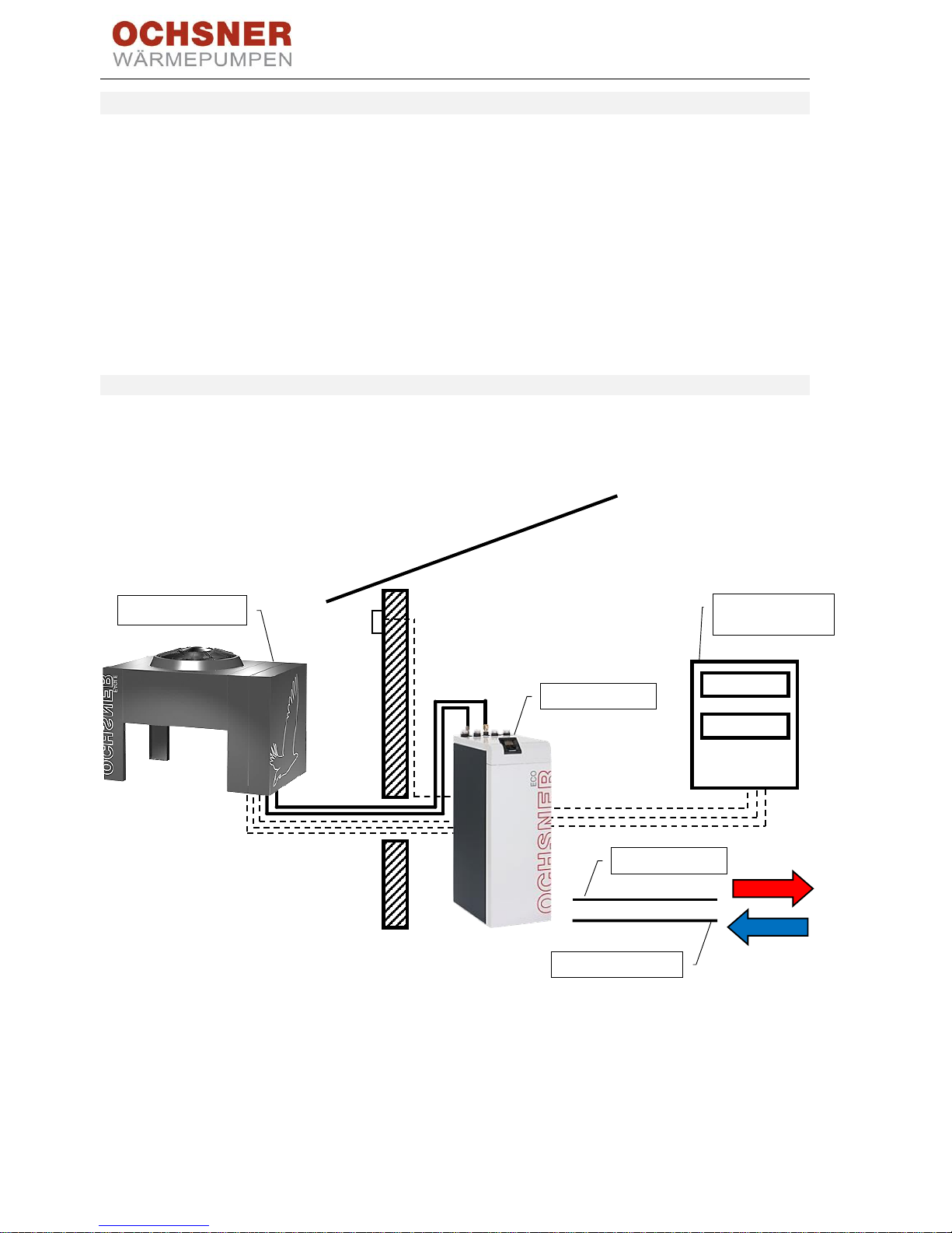
2.5 System overview
The heat pump consists of a split outdoor unit and
an indoor unit which is installed in the boiler room.
The connection to the heating system is made via
the flow and return of the heat sink side of the
heat pump.
Figure 1: System overview
EAGLE indoor
Primary/secondary
distribution
EAGLE outdoor unit
Heating return
Heating flow
BA_OCHSNER AIR EAGLE_414_717_V06_EN.docx Page 7 of 76
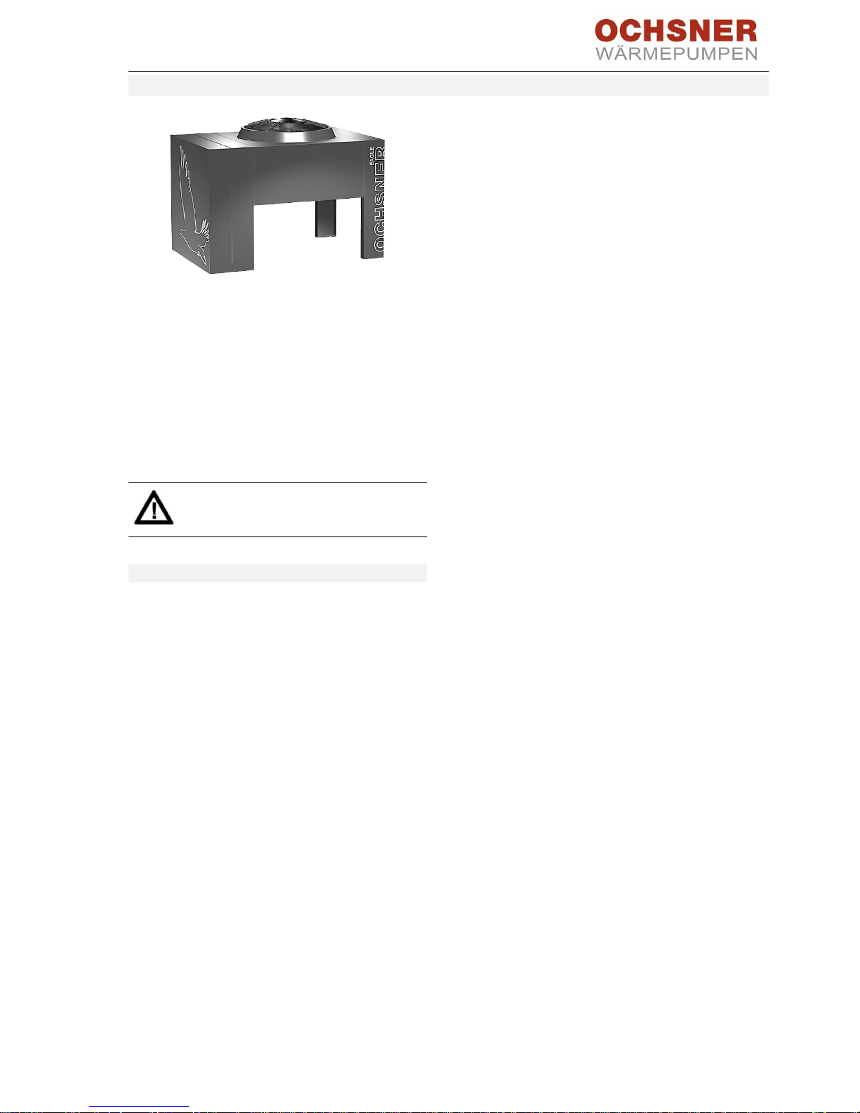
3 Outdoor unit
Figure 2: EAGLE outdoor unit
The EAGLE outdoor unit is installed outdoors on a
plinth provided on site. The outdoor unit consists
of a sound-insulated casing for the horizontal fan
and refrigerant circuit components, such as the
evaporator, compressor, expansion valves and
others. It should be installed as closely as possible
to the indoor unit. The minimum clearances to
walls and recesses should be observed for
installation.
CAUTION Risk of injury!
Never remove the grille from the fan.
3.1 Choosing the installation location
The heat pump can be installed at altitudes of up
to 1000 m above sea level.
High wind loads on the outdoor unit can cause
problems with defrosting in defrosting mode.
Avoid installation in an open and exposed location
with high expected wind loads (e.g. flat roof of a
house in a raised location).
Select an installation location where the appliance
is on the side of the building facing away from the
wind (leeward side).
Avoid acoustic reflections when installing the
EAGLE outdoor unit:
• Avoid installation on reverberant floors.
• Installation between two walls can lead to
increased sound levels.
• Avoid installation next to bedrooms.
• Plants and planted areas can reduce sound
levels.
Provide a frost-free drain for any condensate to
drain away. A gravel bed with drainage connection
underneath the evaporator is sufficient. In winter,
ice may form around the drain.
Please note the following with regard to
installation in coastal areas:
• The outdoor unit must be installed at least
1 km away from the sea.
• The installation location selected should
always be on the leeward side of the building
(the side facing away from the sea).
BA_OCHSNER AIR EAGLE_414_717_V06_EN.docx Page 8 of 76
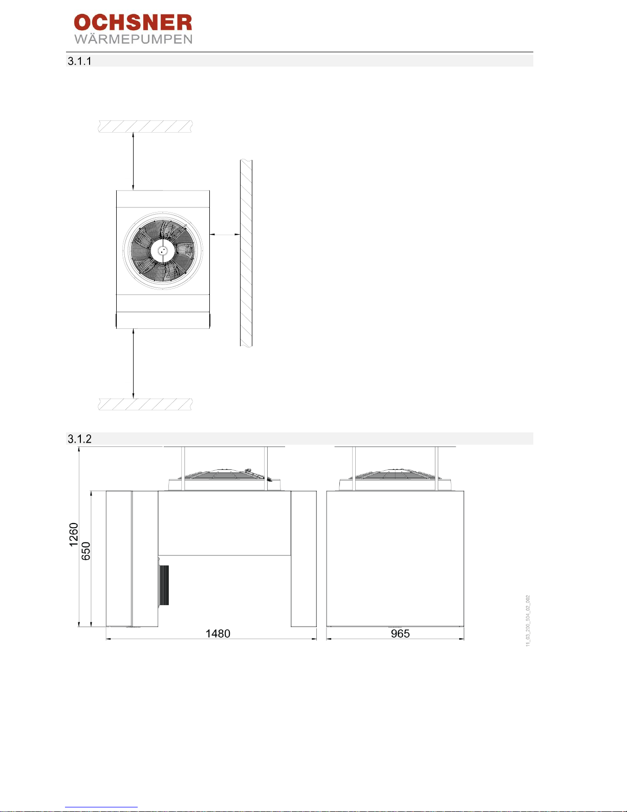
Minimum wall clearances
Do not place the outdoor unit in a recess. The
diagram shows the minimum wall clearances.
Figure 3: Outdoor unit minimum clearances (in mm)
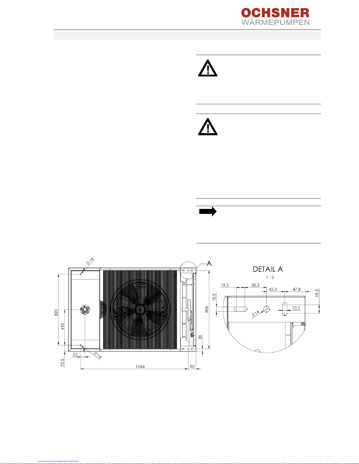
Dimensions
Figure 4: Outdoor unit dimensions (in mm)
min. 1000
min. 500
min. 1000
BA_OCHSNER AIR EAGLE_414_717_V06_EN.docx Page 9 of 76
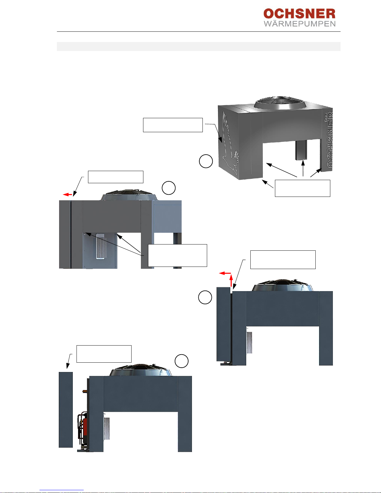
3.2 Opening the outdoor unit
The EAGLE outdoor unit is delivered as a closed
unit. It has to be opened for the connection of the
refrigeration and electric system. We recommend
securing the outdoor unit before removing the
casing cover.
Procedure:
1. Secure the outdoor unit
2. Undo screws on the cover
3. Lift cover out
4. Remove cover
Cover can now be
removed
4
3
Slide cover upwards out
of the bracket
2
Undo 2 hexagon
socket 6 screws
M8x200
Release cover
Secure the
outdoor unit
1
Casing cover
BA_OCHSNER AIR EAGLE_414_717_V06_EN.docx Page 10 of 76
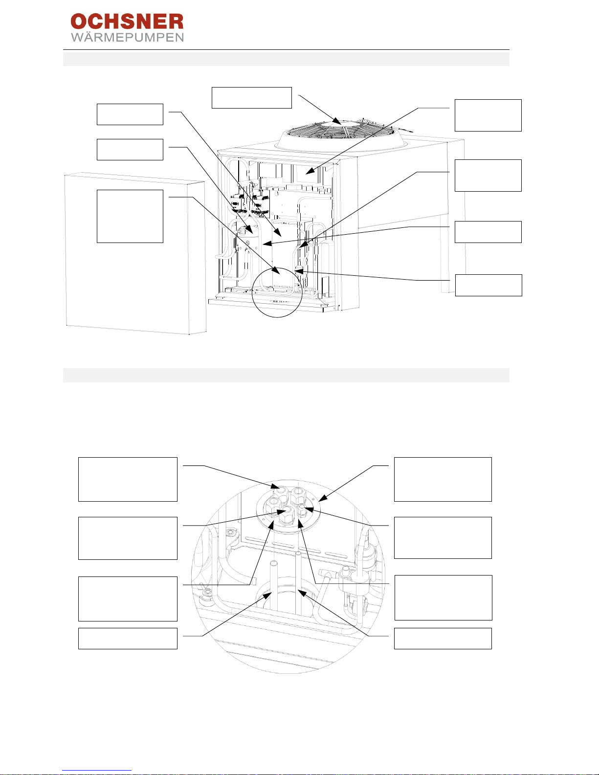
3.3 Main components
Figure 5: Outdoor unit main components
3.4 Cable entries
Remove the mounting plate to pass through the
hot gas and liquid pipes as well as the 3 supply
cables. After the outdoor unit has been
positioned, the pipes can be aligned and cables
passed through. When everything is ready, realign the mounting plate and tighten the cable
entries.
Figure 6: Outdoor unit conduits
Outdoor unit
control box
Compressor
Fan motor
Inverter
Refrigerant
circuit
Connection
line conduit
Cable entries
Liquid line
Hot gas line
Cable entries for control
cables
M25 x 1.5
Liquid line
Hot gas line
Conduits
Hot gas line
M25 x 1.5
Mounting plate
removed
Cable entry for BUS
cable
M16 x 1.5
Cable entry for power
supply
M25 x 1.5
Conduit
Liquid line
M25 x 1.5
BA_OCHSNER AIR EAGLE_414_717_V06_EN.docx Page 11 of 76
3.5 Foundation for the outdoor unit
A permanent foundation is required beneath the
outdoor unit. The foundation must meet the load
bearing requirements of the outdoor unit (see
section 13, Specification).
• Provide for frost-free drainage (e.g. a gravel
bed with a frost-free connection to a drain)
for condensation that forms on the outdoor
unit.
• Where refrigerant lines are to be laid in the
ground, ensure correct positioning of the
pipe liner when laying the foundations.
• Use rigid underground sewage pipes or
flexible, double-skinned cable ducts (smooth
on the inside) for the pipe liner.
• This must be done in accordance with the
relevant Building Codes of Practice and
regulations.
Take the expected wind loads at the
installation site into consideration.
Ensure that the outdoor unit is
adequately secured to the foundation
to prevent it from tipping over due to
wind loads.
CAUTION: Slipping hazard
If drainage for condensation is
inadequate, ice can build up in winter
in the area around the outdoor unit.
- Ensure drainage for
condensation is sufficient even
at low temperatures.
- Ensure that no ice is formed,
especially around walking
surfaces and entrances around
the outdoor unit.
NOTE
Insulation used beneath the soil must
be made of a closed-cell material.
Otherwise, the thermal insulation of
the material will be impaired.
Figure 7: EAGLE outdoor unit (view from below), fixing holes in the outdoor unit legs (dimensions in mm)
BA_OCHSNER AIR EAGLE_414_717_V06_EN.docx Page 12 of 76
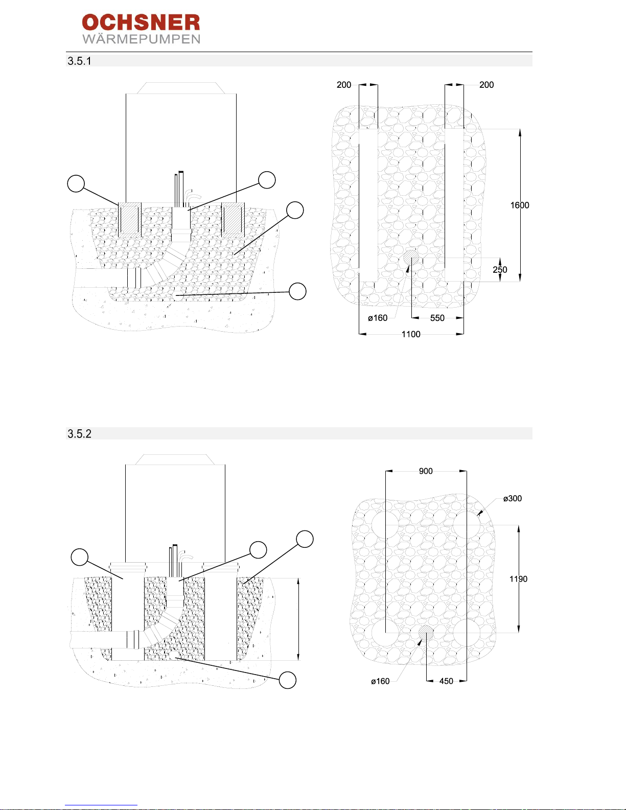
Strip foundation
1
Strip foundation
2
Pipe liner for the connecting lines (where installed underground)
3
Gravel bed
4
Drainage pipe (frostproof)
Figure 8: Strip foundation (dimensions in mm)
Spot foundation
1
Spot foundation
2
Pipe liner for the connecting lines (where installed underground)
3
Gravel bed
4
Drainage pipe (frostproof)
Figure 9: Spot foundation (dimensions in mm)
2
1
3
4
min. 800
2
1
3
4
BA_OCHSNER AIR EAGLE_414_717_V06_EN.docx Page 13 of 76
Concrete plinth
Figure 10: Installation on concrete plinth (dimensions in mm)
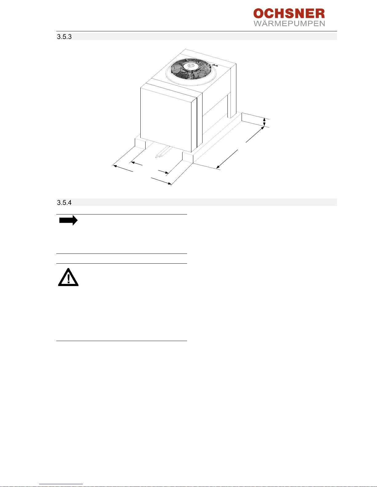
Installing on flat roofs
NOTE
Avoid installing the EAGLE outdoor unit
on roofs over living spaces or car ports
attached to living spaces due to the risk
of structure-borne noise transmission.
WARNING Risk of falling
Working on a flat roof without fall
protection constitutes a risk.
• When working on a flat roof,
observe the laws relating to
occupational safety in your
region.
• Always be aware of the open
edge.
Loads and stresses on roof structure
Note that when outside temperatures are very
low, ice can form beneath the outdoor unit.
In terms of roof structure loads, allow for an ice
load of 400 kg/m² in addition to the dead weight
of the outdoor unit.
When installing the EAGLE outdoor unit on top of
a freestanding car port, a garage or a storage
space, please note the following:
• Provide a suitable plinth for roof installation.
• Take the concentrated load arising from the
dead weight of the outdoor unit (subject to
the type of plinth) and the surface load
caused by possible build-up of ice into
consideration.
• Ensure suitable sound insulation between the
outdoor unit and the installation points on
the plinth.
• Use suitable anti-vibration pads between the
plinth and the outdoor unit legs (OCHSNER
accessory no. 290698) – see Figure 11.
• Provide sound insulation between the
outdoor unit legs and the plinth – see
Figure 11.
• Use suitable sound-insulating pipe fixings to
secure the refrigerant lines.
700
min. 1600
1100
200
BA_OCHSNER AIR EAGLE_414_717_V06_EN.docx Page 14 of 76
1
Base
2
Anti-vibration mount
3
Rubber grommet
4
Washer
5
Fixing screw
Figure 11: EAGLE outdoor unit secured with structure-borne noise attenuating fixings
1
Flat roof
2
Refrigerant lines in open air with thermal insulation and UV protection
3
Base
4
Anti-vibration mount
Figure 12: Flat roof installation of EAGLE outdoor unit (dimensions in mm)

BA_OCHSNER AIR EAGLE_414_717_V06_EN.docx Page 15 of 76
4 Indoor unit
The indoor unit is installed in the heating distribution room or any other suitable room. The indoor unit
contains the condenser and all hydraulic components required for operation with a water-filled heating
system. Observe the minimum clearances to the wall and recesses when installing the unit and ensure the
maximum room temperature does not exceed 30°C.
4.1 Golf-Midi indoor unit
Main components
Figure 13: Indoor unit detailed view
Indoor unit
control box
OTE controller
MFA module with
• 3-way switching valve
• Safety valve
• Electric auxiliary heater
8.8 kW
• Flow sensor
• Air vent
Circulation pump
Plate heat ex-
changer
Condenser
Expansion vessel
Service valve for
expansion vessel
Valve for filling and
draining
DHW
flow
Heating
flow
Heating
return
DHW
return
Bypass connection
BA_OCHSNER AIR EAGLE_414_717_V06_EN.docx Page 16 of 76
Connections
Figure 14: View from above
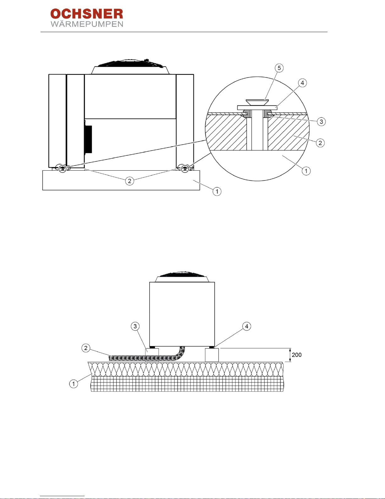
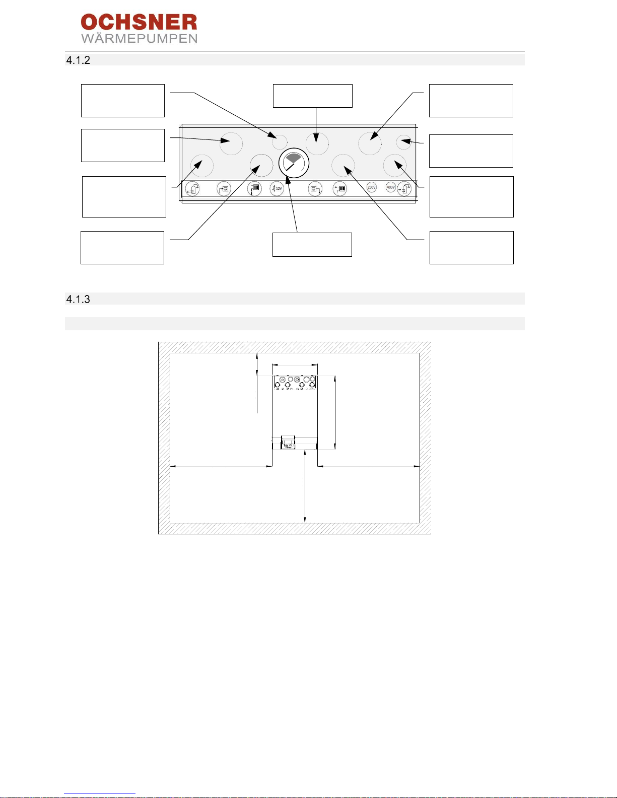
Choosing the installation location
4.1.3.1 Minimum wall clearances
Figure 15: Minimum wall clearances
Room
temperature
<30°C
Controller voltage
230 V~
Booster heater
400 VAC
Sensors <12 V
Liquid line
DHW heating
return
Heating
return
DHW heating
flow
Heating
flow
Hot gas line
Pressure gauge
b
bar
40 cm
min 40 cm
min 40 cm
min 100 cm
65 cm
min 5 cm
BA_OCHSNER AIR EAGLE_414_717_V06_EN.docx Page 17 of 76
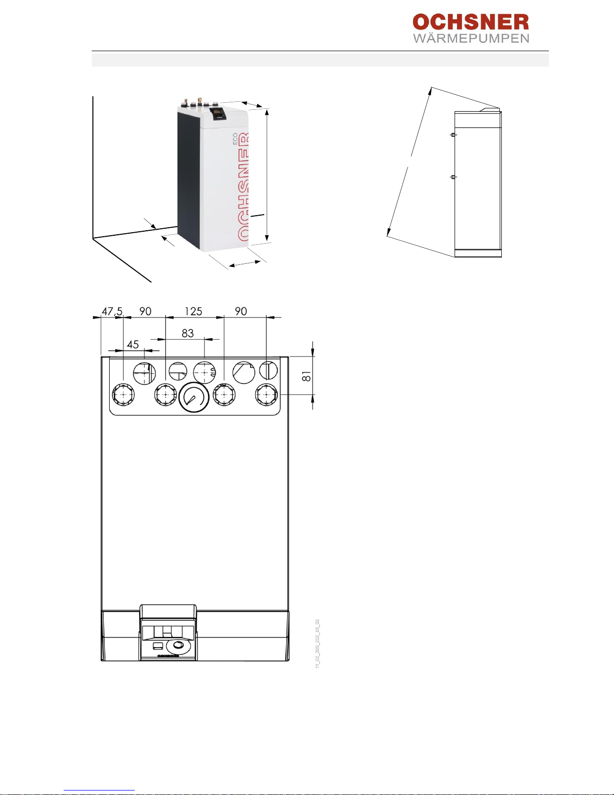
4.1.3.2 Dimensions
Figure 16: Indoor unit dimensions
Figure 17: Indoor unit tilt height
Figure 18: Indoor unit connection dimensions
min. 50 mm
1150 mm
400 mm
650 mm
approx. 132 cm
BA_OCHSNER AIR EAGLE_414_717_V06_EN.docx Page 18 of 76
Venting the system
Figure 19: Indoor unit air vent valve
CAUTION
Close the valve cap after venting.
Safety valve
NOTE
Water will escape when the safety
valve is opened. Route the drain hose
into the sewage drain at the rear of the
indoor unit. The drain must not be
permanently connected to the sewage
drain! A funnel with a siphon must be
provided.
- Size the drain hose to ensure water can drain
freely when the safety valve is fully open.
- Ensure that the safety valve drain hose is open
to the atmosphere.
- Route the safety valve drain hose with a
continuous slope to the drain.
- Secure the drain hose to prevent movement
when water is running out.
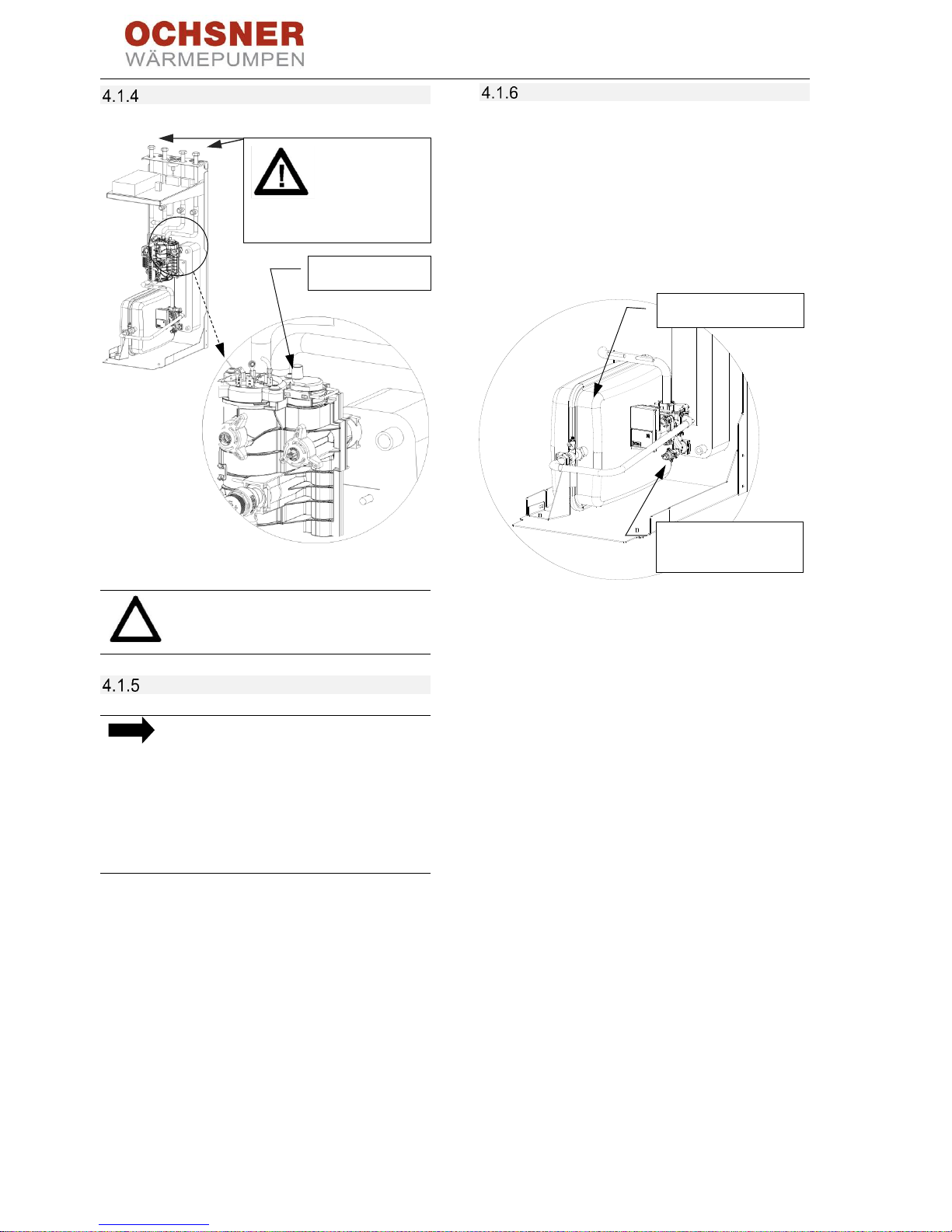
Expansion vessel/system pressure
Preparation for filling:
A 24 l expansion vessel is installed in the heat
pump Golf-Midi indoor unit. In buffer systems or
systems with higher capacity, this expansion
vessel should be checked. If required, install an
additional expansion vessel in the system
(externally, not inside the appliance).
Figure 20: Draining and filling detailed view
Before filling the system, check the pre-charge
pressure in the expansion vessel. This must be
matched to the building height.
- Static head: Difference between highest and
lowest points in the system.
- Pre-charge pressure = static head + 0.3 bar
- System charge pressure = pre-charge pressure
+0.5 bar (when cold)
- Max. permissible operating pressure: 2.6 bar.
Select a safety valve with 3.0 bar.
See EN ISO 4126-1:2013-10-15, part 1: Safety
valves.
- Flush the heating system thoroughly before
filling.
- Only fill with water of potable quality.
CAUTION!
Replace plastic closures with
suitable plugs.
Air vent valve
Drain and fill opening
Expansion vessel
BA_OCHSNER AIR EAGLE_414_717_V06_EN.docx Page 19 of 76
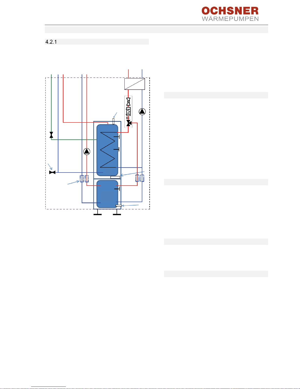
4.2 T200 (MULTI TOWER) indoor unit
Appliance description
The buffer tank and the DHW tank with heat
exchanger are arranged on top of each other and
can be separated for handling.
1
Heat pump
2
Hot gas
3
Liquid
4
Buffer charging pump
5
Multifunctional assembly (MFA)
6
Magnesium anode
7
Cable grommet
8
Drain stopcock
9
Heating circuit
10
DHW circulation
11
Cold water
12
DHW
13
Connecting hoses
14
Buffer tank
15
DHW tank
Figure 21: T200 hydraulic schematic
The appliance is fitted with a plastic foam outer
casing and a removable front panel. The appliance
is connected hydraulically and electrically to the
heat pump. All hydraulic connections are at the
top.
Further system components are integrated
alongside the DHW tank and the buffer tank:
Heat pump manager, tank charging pump, high
efficiency circulation pump for one direct heating
circuit, multifunctional assembly with safety valve
and 3-way switching valve, emergency/booster
heater for mono energetic operation.
4.2.1.1 DHW tank
The steel tank is fitted internally with a special
direct enamel and a sacrificial anode. The anode
with wear indicator protects the inside of the tank
against corrosion.
The heating water heated by the heat pump is
pumped through an internal indirect coil in the
DHW tank. The internal indirect coil transfers the
absorbed heat to the DHW. The integral heat
pump manager controls DHW heating to the
required temperature.
4.2.1.2 Buffer tank
The steel tank serves to hydraulically separate the
flow rates of the heat pump and the heating
circuit. The heating water heated by the heat
pump is transported to the buffer tank by the tank
charging pump. When there is a demand, the
heating water is supplied to the heating circuit by
the integral heating circuit circulation pump.
4.2.1.3 Heat pump manager (OTE)
The system is controlled via the integral OTE3 heat
pump manager. For adjustment options, see the
controller operating manual.
4.2.1.4 Multifunctional assembly (MFA)
The multifunctional assembly switches between
heating circuit and DHW heating.
10
11
12 9 2
1 3 5
6
8
7
13
8
4
14
15
BA_OCHSNER AIR EAGLE_414_717_V06_EN.docx Page 20 of 76
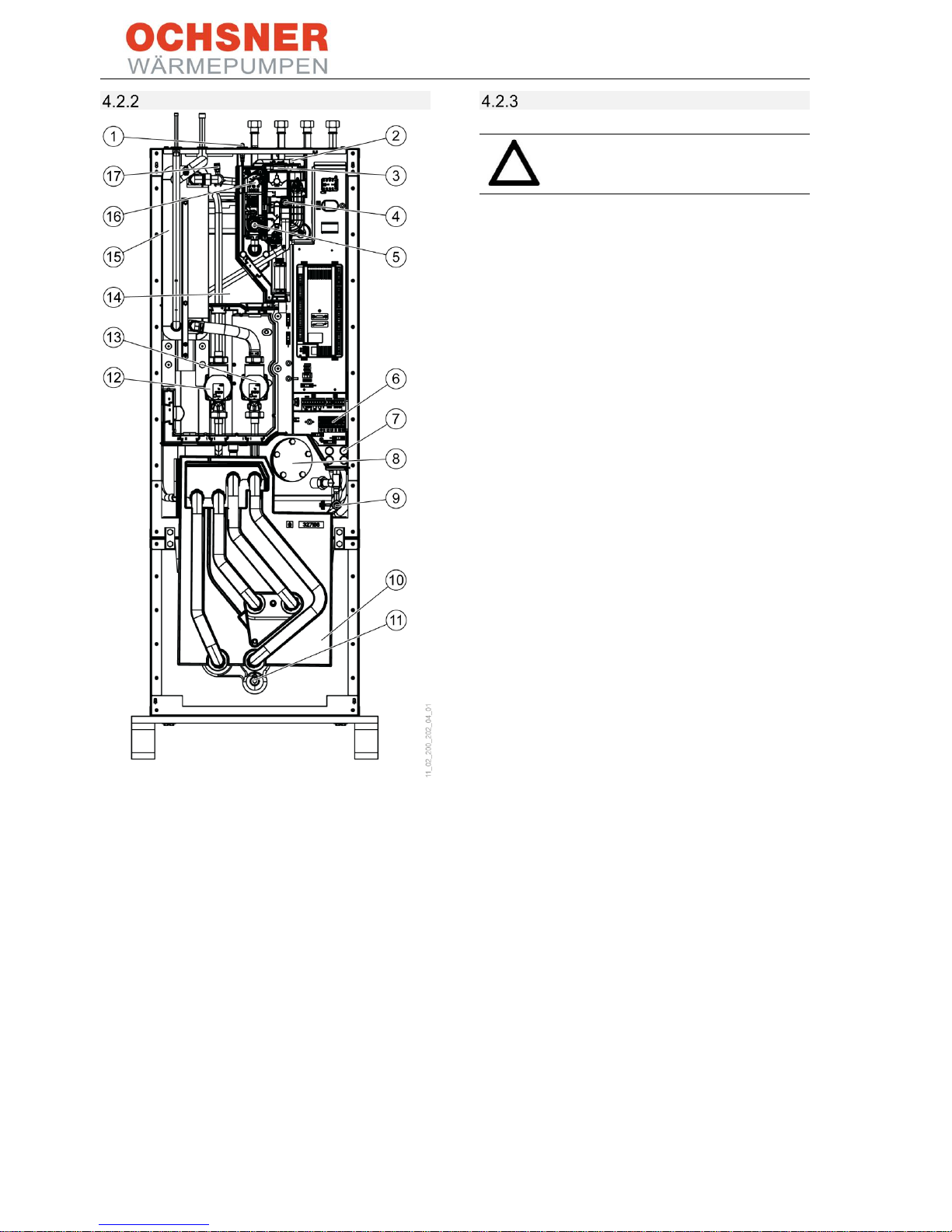
Main components
1
Magnesium anode
2
Air vent valve (MFA)
3
Electric booster heater 8.8 kW (MFA)
4
Safety valve (MFA)
5
3-way switching valve (MFA)
6
Electrical connection
7
Cable entries
8
Maintenance flange
9
Drain stopcock
10
Buffer tank (100 l)
11
Drain stopcock
12
Heating circuit pump
13
Buffer charging pump
14
DHW tank (168 l)
15
Condenser (plate heat exchanger)
16
High limit safety cut-out (MFA)
17
Air vent valve
Figure 22: Main components in T200 indoor unit
Choosing the installation location
CAUTION
Do not install the appliance in damp
rooms!
Install the appliance in a frost free and dry room
near the draw-off point. In order to reduce line
losses, keep the distance between the indoor unit
and the outdoor unit small.
Ensure that the floor has adequate load bearing
capacity and is sufficiently level (for weight, see
section 13, Specification). The room must not be
endangered by explosive dust, gases or vapours.
If installing the appliance in a boiler room with
other heating appliances, ensure that their
operation is not affected.
BA_OCHSNER AIR EAGLE_414_717_V06_EN.docx Page 21 of 76
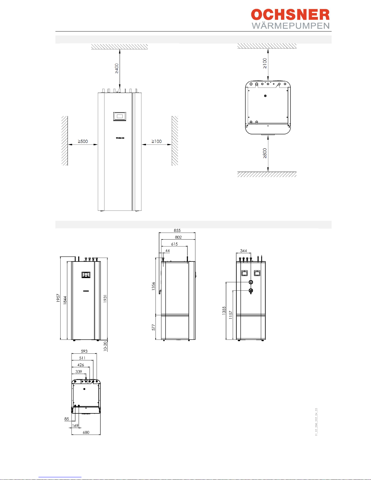
4.2.3.1 Minimum wall clearances
Figure 23: Minimum clearances (in mm)
Minimum clearances to the side can be either to
the right or the left.
4.2.3.2 Dimensions
Figure 24: Dimensions (in mm)
BA_OCHSNER AIR EAGLE_414_717_V06_EN.docx Page 22 of 76
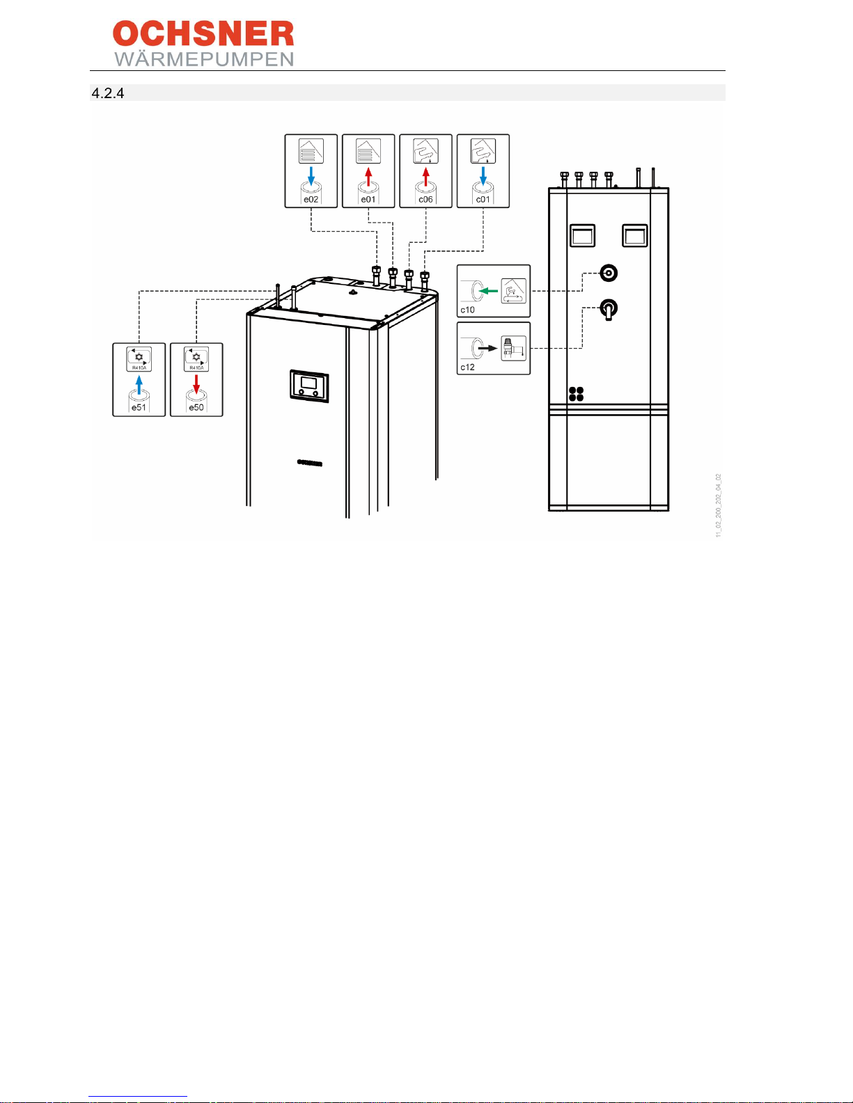
Hydraulic and refrigerant connections
e01
Heating circuit flow 1" union nut with flat gasket
e02
Heating return 1" union nut with flat gasket
e50
Hot gas line
e51
Liquid line
c01
Cold water inlet 1" union nut with flat gasket
c06
DHW outlet 1" union nut with flat gasket
c10
DHW circulation 12 mm copper
c12
Safety valve drain
Figure 25: Hydraulic connections and labels, T200 refrigeration
BA_OCHSNER AIR EAGLE_414_717_V06_EN.docx Page 23 of 76
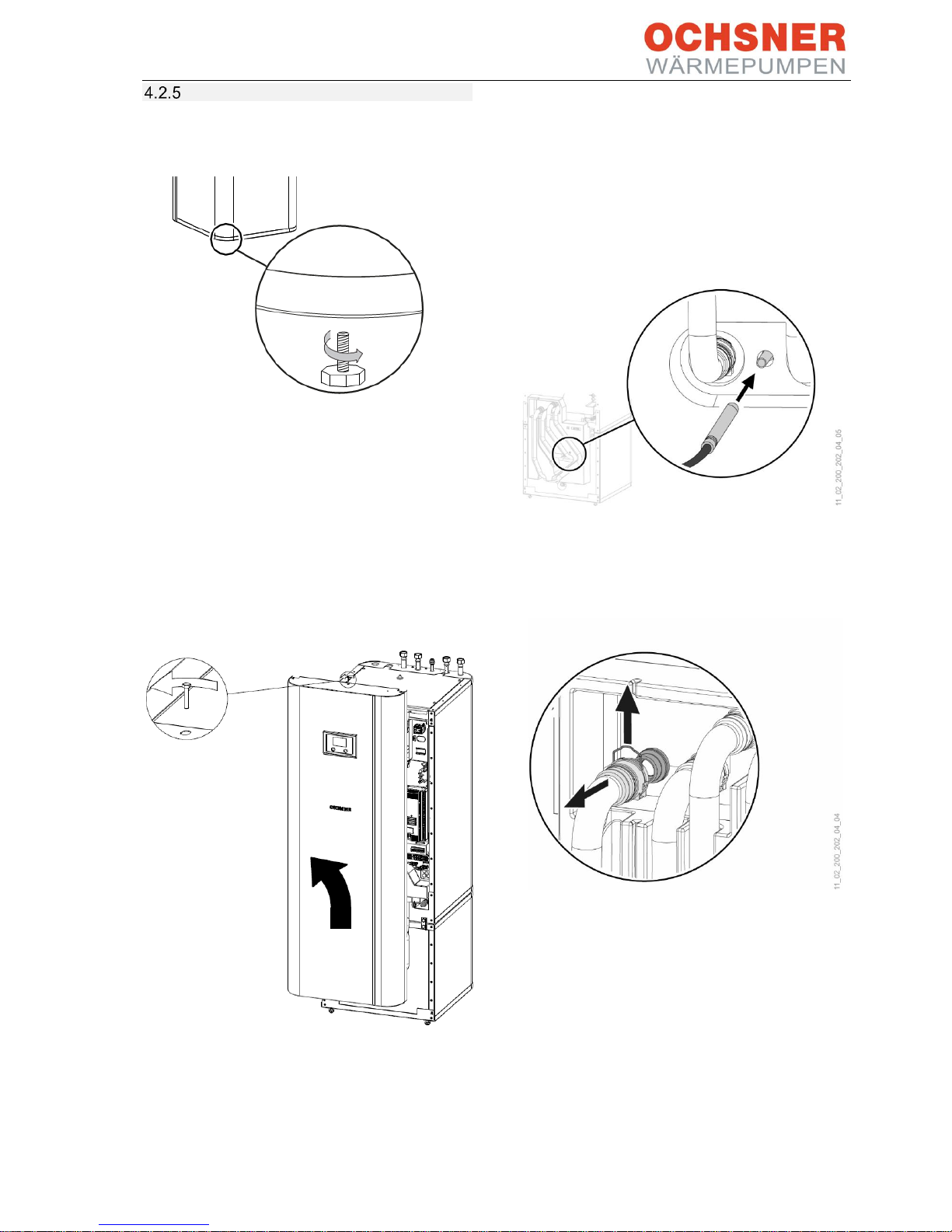
Transport and handling
- Remove the 4 screws from the non-
returnable pallet.
Figure 26: Removing the fixing screw
- Slightly tilt the appliance and screw in the
4 adjustable feet supplied.
- Lift the appliance from the pallet.
Should narrow doors or corridors impede
handling, the top and bottom sections of the
appliance can be separated as described in the
following sections.
Removing the front cladding:
- Remove the screw from the top centre of the
appliance.
- Unhook the front cladding towards the top.
- Disconnect the control panel plug and the
front panel earth wire.
Installing the front cladding
Install the front cladding in reverse order.
Separating the appliance sections:
Figure 27: Pull the sensor from the buffer tank.
- Pull out the sensor on the buffer tank.
- Remove the sensor cable from the guiding
groove in the insulation element.
Figure 28: Undoing the plug-in connectors
- Undo the plug-in connectors of the 4 hydraulic
connections. Pull out the spring clips fully
using a screwdriver.
- Pull off the hydraulic connections towards the
front.

BA_OCHSNER AIR EAGLE_414_717_V06_EN.docx Page 24 of 76
Figure 29: Removing the hydraulic hoses
- Remove the 4 hydraulic hoses and the thermal
insulation element.
Figure 30: Undoing the connecting screws
- Undo the 4 screws on the tabs at the front of
the appliance.
Figure 31: Separating the appliance sections 1
- Pull the top section towards the front.
Figure 32: Separating the appliance sections 2
- Tilt the top section towards the back. Use the
grip rail for better grip during transport.
Figure 33: Setting down the T200 top section
- Set the top appliance section on a pad or mat
to avoid damage.
Assembling the appliance sections:
Assemble the appliance sections in reverse order.
The positioning aids and dotted line markings
facilitate sliding the top appliance section into the
guide on the lower section.

BA_OCHSNER AIR EAGLE_414_717_V06_EN.docx Page 25 of 76
1
Grip rail
2
Guide pin
3
dotted line (perforation in the metal plate)
4
Guide groove
5
Positioning aid
Figure 34: Assembling the appliance sections 1
1
dotted line (perforation in the metal plate)
Figure 35: Positioning aid
- Place the top appliance section onto the
bottom appliance section at the dotted line.
Figure 36: Assembling the appliance sections 2
- Slide the top appliance section towards the
rear until it is flush with the bottom section.
When the appliance sections are assembled
correctly, the end position is given by the
guide groove and the guide pin.
- Fasten the tabs at the front of the appliance.
- Fit the thermal insulation element and the
4 hydraulic hoses.
- Fit the plug-in connectors of the 4 hydraulic
connections. Ensure that the spring clips
engage.
- Plug in the sensor on the buffer tank.
- Route the sensor cable in the guiding groove
in the thermal insulation element.

BA_OCHSNER AIR EAGLE_414_717_V06_EN.docx Page 26 of 76
Safety valve
1
Drain pipe
2
Mounting
3
Drain
Figure 37: Drain hose, safety valve
- Size the drain hose to ensure water can drain
freely when the safety valve is fully open.
- Ensure that the safety valve drain hose is open
to the atmosphere.
- Route the safety valve drain hose with a
continuous slope to the drain.
- Secure the drain hose to prevent movement
when water is running out.
DHW connection and safety assembly
CAUTION
Do not exceed the maximum pressure
(see section 13, Specification).
CAUTION
The appliance must be operated with
pressure fittings.
Cold water pipe:
Permitted materials are galvanised steel, stainless
steel, copper and plastic.
CAUTION
A safety valve is required.
DHW line:
Permitted materials are stainless steel, copper and
plastic.
Installing the DHW circulation line
A DHW circulation line with an external
DHW circulation pump can be connected at the
"DHW circulation" connection.
- Remove the sealing flap from the "DHW
circulation" connection.
- Connect the DHW circulation line.
Connection:
- Thoroughly flush the pipes.
- Install the DHW outlet pipe and the cold water
inlet pipe (see section 4.2.4 Hydraulic and
refrigerant connections).
- Install a type-tested safety valve in the cold
water inlet pipe. Note that, depending on the
supply pressure, a pressure reducing valve
may be additionally required.
- Size the drain pipe to ensure water can drain
freely when the safety valve is fully open.
- The safety valve drain opening must remain
open to the atmosphere.
- Route the safety valve drain pipe with a
continuous slope.
1
2
3

BA_OCHSNER AIR EAGLE_414_717_V06_EN.docx Page 27 of 76
Filling the system
Filling the heating system:
Figure 38: Filling the heating system
- Fill the heating system via the drain valve.
- Vent the pipework.
NOTE
For easier filling, the 3-way switching
valve (multifunctional assembly) is set
to a position suitable for filling at the
factory. The cable from the switching
valve to the OTE controller has been
disconnected at the factory.
➔ Once the system is successfully
filled, connect the plugs PIN3/N/PE
and PIN4/N/PE on the OTE
controller.
Filling the DHW tank:
- Fill the DHW tank via the cold water
connection.
- Open all downstream draw-off valves until the
appliance is filled and the pipework is free
from air.
- Adjust the flow rate. Observe the maximum
permissible flow rate with fully opened valve
(see Specification). If necessary, reduce the
flow rate at the throttle on the safety
assembly.
- Carry out a leakage test.
- Test the safety valve.
BA_OCHSNER AIR EAGLE_414_717_V06_EN.docx Page 28 of 76
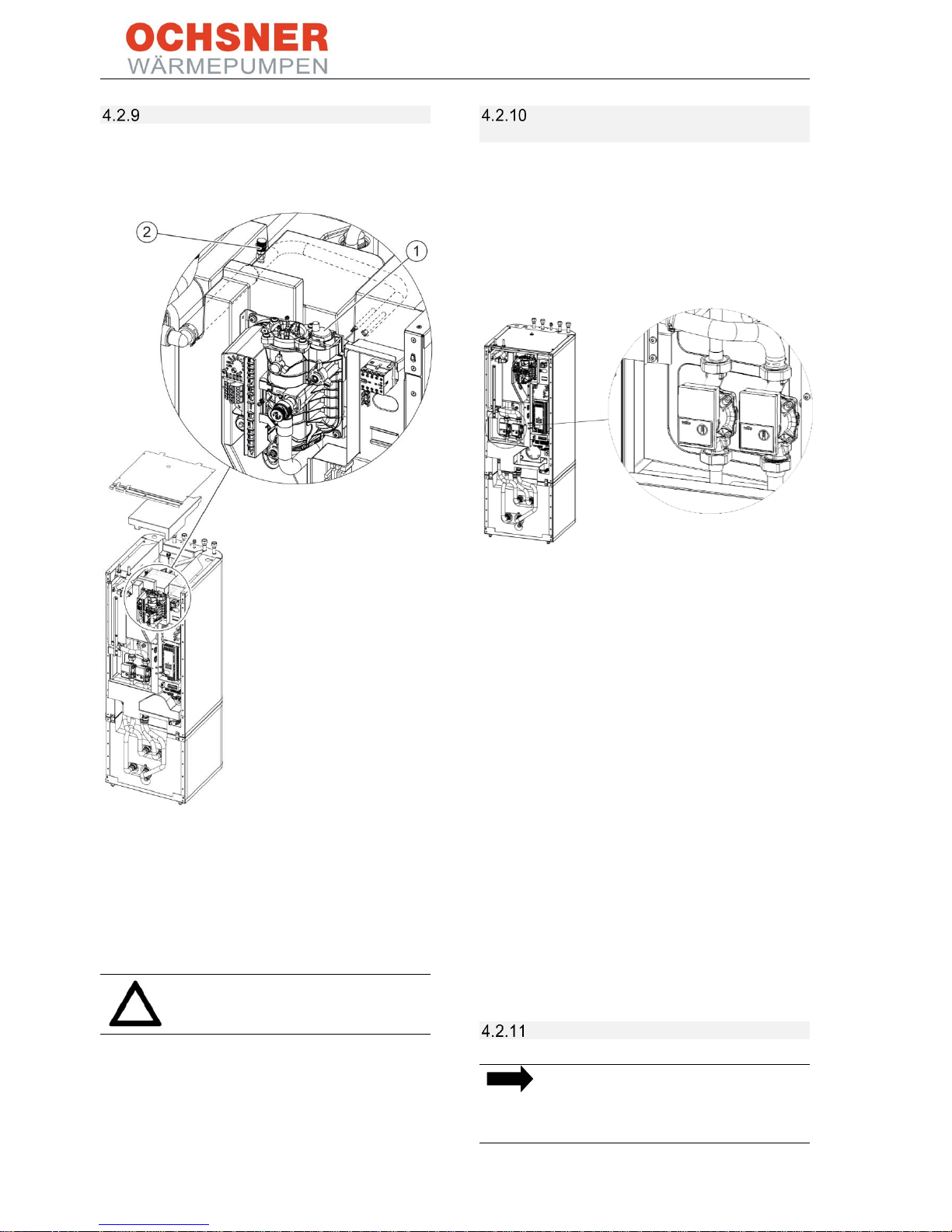
Venting the system
- To vent the system, temporarily open the air
vent valve (1) on the multifunctional
assembly.
There is another air vent valve underneath the
top appliance cladding.
- Remove the top appliance cladding.
- Remove the thermal insulation material
underneath.
- To vent the system, temporarily open the air
vent valve (2).
CAUTION
Close the air vent valves after venting.
Using T200 with a heating circuit with
mixing valve
To use the T200 (MULTI TOWER) indoor unit with
a heating circuit with mixing valve, the internal
heat circuit pump must be replaced with an
adaptor.
The heating circuit pump is the left-hand pump in
the upper section of the T200.
Adaptor:
The adaptor needs to have the following
dimensions:
- Connections 2 x 1½" MT, with flat gasket
- Length 180 mm
- Nominal diameter DN 25 (1")
The adaptor is available from OCHSNER as an
accessory with the item number 914383.
Subsequently, the heating circuit (or several) can
be set up externally.
Connect the components of the mixed circuit to
the following connections on the OTE controller:
- Mixer: PIN 15/16/N/PE
- Mixed circuit sensor: PIN 43/GND
- Mixed circuit pump: PIN 8/N/PE
Recommission the controller with heating circuit 2
in mixed configuration. In case of more than one
mixed circuit, an auxiliary module (order
no. 290197) is required.
Cooling with T200
NOTE
Only gentle cooling down to a flow
temperature of 18°C is permitted with
the T200 indoor unit!

BA_OCHSNER AIR EAGLE_414_717_V06_EN.docx Page 29 of 76
T200 maintenance
CAUTION
Before any work is carried out, all
electrical connections to the appliance
must be isolated from the mains across
all poles.
Draining the buffer tank:
Figure 39: Draining the buffer tank
- Drain the buffer tank via the drain valve.
Draining the DHW tank:
CAUTION Risk of scalding
Hot water can escape when draining
the DHW tank.
- Close the shut-off valve in the cold water inlet
pipe.
- Open the DHW valves on all draw-off points.
Figure 40: Draining the DHW tank
- Drain the DHW tank via the drain valve.
Cleaning and descaling the DHW tank:
CAUTION
Do not use a descaling pump or
descaling agent to clean the tank.
- Clean the appliance via the inspection flange.
- For tightening torques and flange bolts, see
Specification.
Sacrificial anode:
CAUTION
If the wear indicator has changed from
a white to red colour, let a qualified
contractor check the sacrificial anode
and replace it if necessary.
1
white = anode OK
2
red = requires checking by qualified contractor
Figure 41: T200 DHW tank sacrificial anode
- Replace the sacrificial anode when it has been
used up.
BA_OCHSNER AIR EAGLE_414_717_V06_EN.docx Page 30 of 76
5 Connection lines
5.1 Refrigerant lines
NOTE
If the appliance, the refrigerant lines,
the fixing points and the wall conduits
are not properly installed, structureborne sound may be transmitted to the
building.
➔ Ensure the refrigerant lines are
secured in a way to minimise
structure-borne sound. The system
installer carrying out the work is
responsible for this.
WARNING
Work on the refrigerant circuit may be
carried out only by an authorised and
suitably qualified contractor.
o When handling refrigerant, wear
appropriate gloves, protective
clothing and protective glasses.
Always position the outdoor unit as closely to the
indoor unit as possible. The maximum length of
the connection line must not exceed a total length
of 25.0 m! Do not exceed a maximum difference in
height of 15.0 m.
Unit
OCHSNER AIR EAGLE 414
OCHSNER AIR EAGLE 717
max. length m < 25
< 25
max. height differential
m
15
15
Refrigerant R410A
R410A
max. operating pressure
bar
45
45
Hot gas line
mm
12
16
Liquid line
mm
10
12

BA_OCHSNER AIR EAGLE_414_717_V06_EN.docx Page 31 of 76
Figure 42: Max. height difference
Figure 43: Oil lift bends
A
Liquid line
B
Hot gas line (thicker copper pipe)
C
Oil lift bend in the hot gas line (min. bending radius 5x diameter)
5.2 Conduit to house
Figure 44: Conduit to house (dimensions in mm)
max. 15 m
A
C
max. 15 m
B
5 m
5 m
Drainage
gravel bed
Drainage pipe
BA_OCHSNER AIR EAGLE_414_717_V06_EN.docx Page 32 of 76
6 Electrical connection
6.1 Preparation
CAUTION!
Before starting any wiring, isolate the
heating system from the power
supply.
DANGER of electric shock
All electrical connection and
installation work must be carried out
according to the relevant national and
regional regulations.
Connection work may only be carried
out by an approved contractor
according to this manual!
The listed fuse protection ratings and cable crosssections are guideline values only! The electrician
connecting up the heat pump is responsible for
selecting the correct safety devices. Cables should
be selected by the electrician taking into account
the output and cable lengths.
WARNING
Before commissioning, the necessary
fault protection measures on the
system and the earth connection must be checked
by a certified electrician. The main power circuit
for the compressor motor has no upstream
power contactor on the machine side. Control
devices and equipment to disconnect and shut
down all supply voltages across all poles, which
must be provided on the system side, must meet
the technical safety requirements of EN 60204-1
sections 5 and 13.4.5, as well as the international
regulations in the IEC 60947 series.
During maintenance or service work, shut down all
heat pump supply voltages on the system side and
observe safety regulations to EN 50110-1.
Failure to observe the technical safety
requirements or precautions may result in serious
injury or death.
Checklist:
• The specified voltage must be consistent with
the grid voltage. Pay attention to the
information on the type plate!
• For connection of the appliance, approval
must be obtained from the relevant power
supply utility.
• Fuse protection for the main power circuit
230 V/400 VAC should be provided via a
circuit breaker, which triggers a shutdown
across all poles in the event of a fault.
• If RCDs (FI) are used, they must trigger an
AC/DC-sensitive shutdown.
• The supply lines must be protected against
surges and short circuits.
• It is essential that the regulations of the
responsible PSU (power supply utility) and
the applicable EN standards are observed.

BA_OCHSNER AIR EAGLE_414_717_V06_EN.docx Page 33 of 76
6.2 Guidelines
Position
min. crosssection
Connection cables 230 VAC:
Always size connection cables
according to the local
conditions.
1.5 mm²
Control cable 230 VAC:
Pumps, actuators
min. 1.0 mm²
Sensor leads:
(outdoor sensors, etc.), sensor
leads are sensitive to EMC and
must always be routed
separately (min. 20 cm) from
230 V/400 V lines. If separation
is not possible, screened cables
should be used. Screening
should be connected to PE on
the heat pump
Max. line length 50 m!
2x 1.0 mm²
Bus leads:
Modbus from outdoor to
indoor unit, room remote
control units, eBus from OTE
controller to room remote
control units, auxiliary
modules, underneath each
other in cascades).
These lines must always be
routed in a screened version.
The screen should be earthed
to PE on the heat pump.
OCHSNER recommends the
following conventional cable:
Y(ST)Y) 2x2x0.8
CAUTION: Always use a
twisted wire pair!
Example: MODEBUS = A/B
Example: eBus = SIGNAL/GND
Do not connect GND to the
screen!
2x2x0.8 mm²
Table 1: Cable selection
6.3 Power connection details
According to the wiring diagram (see section 6.15,
Wiring diagrams) the 400 VAC and 230 VAC power
supplies should be provided separately. The
following power supplies must be provided:
Figure 45: Power supply
A
400 V (230 V) compressor supply
B
PSU signal contact (indoor unit control box)
C
230 V controller supply (indoor unit control
box)
D
400 V (230 V) electric booster heater (indoor
unit control box)
E
Option: 400 V (230 V) DHW auxiliary heater for
anti-legionella function.
The 230 VAC controller power supply to the
outdoor unit is via terminal strip X2 in the indoor
unit control box (L N PE). This ensures that the
outdoor unit and the indoor unit are in phase.
If it is not possible to comply with the
100 mm minimum clearances between
sensor leads and 230 V/400 V, then
screened cables should be used.
The listed fuse protection ratings are guide values
only! The electrician connecting up the heat pump
is responsible for selecting the correct safety
devices.
OCHSNER does not accept liability for faults
resulting from incorrectly designed safety devices!
*PSU = power supply utility
A
B C D
E
BA_OCHSNER AIR EAGLE_414_717_V06_EN.docx Page 34 of 76
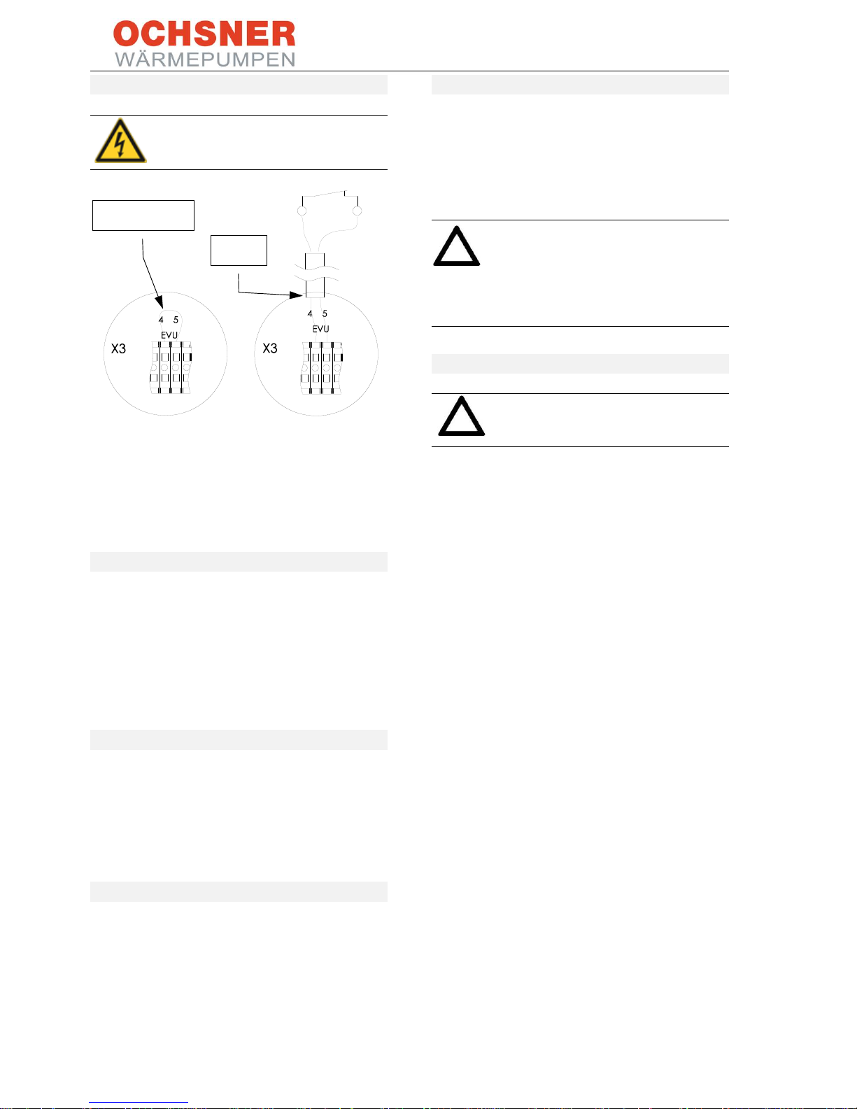
6.4 PSU signal contact
CAUTION!
There is a 230 VAC control voltage
present on the PSU signal contact!
Figure 46: PSU signal contact
Remove the jumper and insert cables as shown in
the drawing. If the PSU signal contact is
interrupted, the compressor and the booster
heater (if installed) will immediately shut down.
6.5 Uninterrupted tariff
In the case of tariff switching without interrupted
power supply, the heat pump is temporarily shut
down by the power supply utility. The PSU signal
contact on the EAGLE indoor unit (terminal
strip X3) should be used for this. To enable the
function, remove the jumper and connect the
cables.
6.6 Shutdown by tariff contactor
In case of shutdown by a tariff contactor (sealed
by the PSU, installed on site), the heat pump
compressor power supply is disconnected. In this
case, the PSU signal contact must be switched via
an auxiliary contact on the tariff contactor
(N/C contact) (otherwise ERROR).
6.7 Night tariff
Where tariff switching takes place within the
meter (night tariff), the PSU signal contact is not
connected.
6.8 Modbus wiring
A Modbus connection is required between the
EAGLE outdoor and indoor units. Communication
between the bus subscribers requires a twisted
cable. Cables of type Y(ST)Y 2x2x0.8 mm² have
proved to be suitable.
CAUTION!
Always use a twisted wire pair.
MODBUS = A/B
eBus = SIGNAL/GND
Do not connect GND to the screen!
6.9 Sensor wiring
Never apply voltage to the sensor
terminals! This would destroy the
controller.
The type NTC5K temperature sensors of the OTE
controller are supplied with a cable length of
4.0 m. If this length is not sufficient, the leads can
be extended to the required dimension. Please
use 2x 1.0 mm² flexible cable.
During installation of the sensor cable, ensure that
the cable is not routed parallel to cables with
AC voltage >230 VAC.
Outdoor sensor TA
Install the outdoor sensor of the controller at a
height of approx. 2.5 m on the outside of the
building wall (facing north-west). Make sure that
the outdoor sensor is not exposed to direct
sunlight or wind, as this will impair the control
characteristics. Also avoid positioning it close to
the evaporator. There may be a risk of influence
on the control.
Mixer sensor TMK
If a mixer circuit is installed in addition to the
direct heating circuit, a mixer sensor must be
installed. The mixer sensor is a contact sensor and
is supplied with the heat pump including a band
clamp and heat conducting paste. Install the mixer
sensor directly downstream of the mixer circuit
pump. When using multi-skin or plastic pipes,
provide a suitable large metal bridge.
Remove jumper
230 VAC
BA_OCHSNER AIR EAGLE_414_717_V06_EN.docx Page 35 of 76
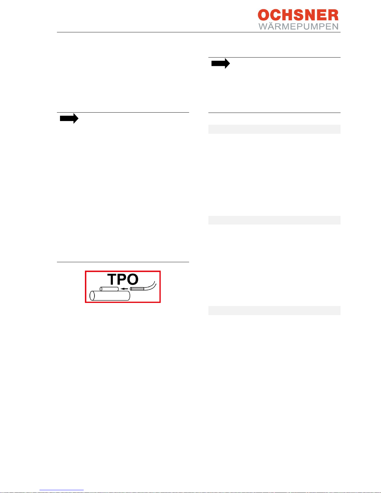
Buffer sensor (TPO, TPM)
Two buffer sensors are required in the buffer tank.
The heat pump is switched on based on readings
from the TPO and switched off based on those
from the TPM.
- Install a sensor pocket in the female socket
provided for the upper buffer sensor (TPO)
- Install a sensor pocket in the female socket
provided for the lower buffer sensor (TPM)
NOTE
In systems with direct heating circuit,
install the TPO sensor in the heating
flow of the heat pump indoor unit.
- Install the TPO sensor in the indoor
unit at the marked location on the
heating flow pipe, downstream
from the electric booster heater
(MFA).
- The required controller parameters
are set by OCHSNER customer
service or specialist personnel
authorised by OCHSNER.
In systems with a buffer tank, a bypass
or a low loss header or a heating
circuit with mixing valve, the TPO
sensor must not be installed in the
indoor unit.
Figure 47: Pipe marking in the heat pump indoor unit
DHW sensor TB
The DHW sensor is included in the delivery of the
heat pump. OCHSNER DHW tanks are fitted with
appropriate female sockets for installing the
sensor.
Install the DHW sensor in the top one-third of the
DHW tank (or at the very least in the top half). The
lower the selected location of the DHW sensor,
the larger the switching hysteresis (5-15 K) will
need to be.
NOTE
Ensure that the DHW sensor is correctly
positioned and extends beyond the
tank insulation into the interior of the
DHW tank. This is the only way in which
the temperature can be measured
correctly.
6.10 Pumps, drives 230 VAC
Pumps (heating circuit pumps, DHW charging
pump) and drives (mixer valves, etc.) are
connected directly to the controller.
A test run may only be carried out on a system that
has been prepared for commissioning! A relay test
can be performed on the OTE controller to check
the relevant outputs (actuators).
6.11 HLSC on the heating circuit
If an on-site high limit safety cut-out (HLSC) is
installed, it can be connected to the HLSC contact
on terminal strip X3. This shuts down the feed
pump. This only applies for hydraulic connection
versions 7.1 and 7.2. In all other versions, the HLSC
must be installed directly in the power supply of
the on-site heating circuit pump.
6.12 DHW booster heater
A separate contactor must be provided in the
electric distribution box for the optional electric
auxiliary heater in the DHW tank (anti-legionella
function). See electrical wiring diagram in section
13, Specification. This function is an option and
therefore not supplied with the heat pump.

BA_OCHSNER AIR EAGLE_414_717_V06_EN.docx Page 36 of 76
6.13 Wiring diagram
The following wiring should be prepared by the system installer for heat pump commissioning by OCHSNER
customer service:
BMK
Cable
Wires
Output/fuse
protection
From (source)
To (target)
1
W1
Power supply
controllers
230 VAC - L/N/PE
Fuse protection: C13A
Primary/second
ary distribution
Indoor unit
2
W2
Power supply
compressor
3x 400 VAC L1/L2/L3/N/PE
or 1x 230 VAC - L/N/PE
EAGLE 717: C16A
EAGLE 414: C20A
Primary/second
ary distribution
Indoor unit
3
W3
Power supply
booster heater
3x 400 VAC L1/L2/L3/N/PE
or 1x 230 VAC - L/N/PE
8.8 kW
3x 400 V, B16A across
all poles
1x 230 V, B40A
Primary/second
ary distribution
Indoor unit
4
W4
Power supply
compressor
3x 400 VAC L1/L2/L3/N/PE
or 1x 230 VAC - L/N/PE
EAGLE 717: C16A
EAGLE 414: C20A
Indoor unit
Outdoor unit
5
W5 Control cable
230 VAC - 23/24/L/N/PE
5x 1.5 mm²
Internal fuse
protection
Indoor unit
Outdoor unit
6
W7
MODBUS
2x 2x 0.8 mm² screened
Indoor unit
Outdoor unit
7
OTE
TA outdoor temperature
sensor
2x 1.0 mm² screened
Indoor unit OTE
Building
exterior wall
8
OTE
eBus to room remote
control (optional)
2x 2x 0.8 mm² screened
Indoor unit OTE
Room remote
control
9
OTE
Communication to
RoomTerminal (optional)
2x 2x 0.8 mm² screened
Indoor unit OTE
RoomTerminal
touchscreen
10
OTE
All required sensors TB,
TMK (optional)
2x 1.0 mm²
Indoor unit OTE
Heating system
11
OTE
All required actuators,
servomotors, pumps
230VAC
at least 1.0 mm²
Indoor unit OTE
Heating system
Table 2: Wiring diagram
Figure 48: Wiring overview
W2 cable 3x400 VAC or
1x230 VAC power supply,
compressor
W3 cable 3x400 VAC or
1x230 VAC power supply,
booster heater
Refrigerant lines
W4 cable 3x400 VAC or
1x230 VAC power supply, com-
pressor
W1 cable 230 VAC
Power supply
controllers
W5 control cable 230 VAC
W7 Modbus cable
1 4 5 6 2
3

BA_OCHSNER AIR EAGLE_414_717_V06_EN.docx Page 37 of 76
NOTE
OCHSNER can provide a cable harness as an accessory for the electrical connection between
indoor unit (Golf-Midi or T200) and outdoor unit. The cable harness combines the Modbus
cable (W7), the control cable (W5) and the compressor supply (W4). For the MULTI TOWER (T200)
an external junction box (X11) must be provided next to the indoor unit.
6.14 Indoor unit wiring
CAUTION
Isolate the system from the power
supply before attempting any
electrical work!
CAUTION
Connecting cable cross-sections should
be sized according to local regulations.
Golf-Midi indoor unit
Terminal
Description
OTE pin
Description
X1
L1/L2/L3 (KM3)
Power supply
electr. booster heater 8.8 kW
(W2)
7
Heating circuit pump 1, direct (HCP 1)
N1/N2/N3/PE
8
Heating circuit pump 2, with mixer valve
(HCP 2)
X2
23/24/LS/N/PE
Control cable to outdoor unit (W5)
13/14
DHW charging pump ON/OFF (WWL)
X3
L/N/PE
Power supply OTE controller (W1)
15/16
Heating circuit mixing valve (MVH)
EVU
PSU signal contact
41/42
Control elements (eBus)

BA_OCHSNER AIR EAGLE_414_717_V06_EN.docx Page 38 of 76
HLSC
External high limit safety cut-out
(heat sink)
43
Mixer sensor (TMK)
44
Outdoor temperature sensor (TA)
10
DHW auxiliary heater
46
DHW sensor (TB)
X11
L1/L2/L3/N/PE
Compressor power supply (W4, to
outdoor unit)
72
Default target value, building
management system (BMS)
MODBUS
B/GND/A
Modbus connection to outdoor unit
Note: If the X11 terminal is not provided in the indoor unit control box on site, provide an external junction box with
X11.
T200 (MULTI TOWER) indoor unit
The appliance control box is located behind the
front panel (see section 4.2.5).
Figure 49: T200 electrical connection
- Route all mains and sensor cables through the
cable entry into the appliance.
Figure 50: T200 indoor unit cable entry

BA_OCHSNER AIR EAGLE_414_717_V06_EN.docx Page 39 of 76
T200 control box:
Terminal
Description
X1
L1/L2/L3
Power supply
electr. booster heater 8.8 kW
N1/N2/N3
X2
23/24/LS/N/PE
Control cable to outdoor unit
X3
L/N/PE
Power supply OTE controller
10
DHW auxiliary heater
1/2 (EVU)
PSU signal contact
1/2
External high limit safety cut-out
(heat sink)
Modbus
B/GND/A
Modbus connection to outdoor
unit OTE pin
Description
8
Heating circuit pump 2, with
mixer valve (HCP 2)
15/16
Heating circuit mixing valve
(MVH)
41/42
Control elements (eBus)
43
Mixer sensor (TMK)
44
Outdoor temperature sensor (TA)
72
Default target value, building
management system (BMS)
Figure 51: T200 indoor unit connection terminals
BA_OCHSNER AIR EAGLE_414_717_V06_EN.docx Page 40 of 76
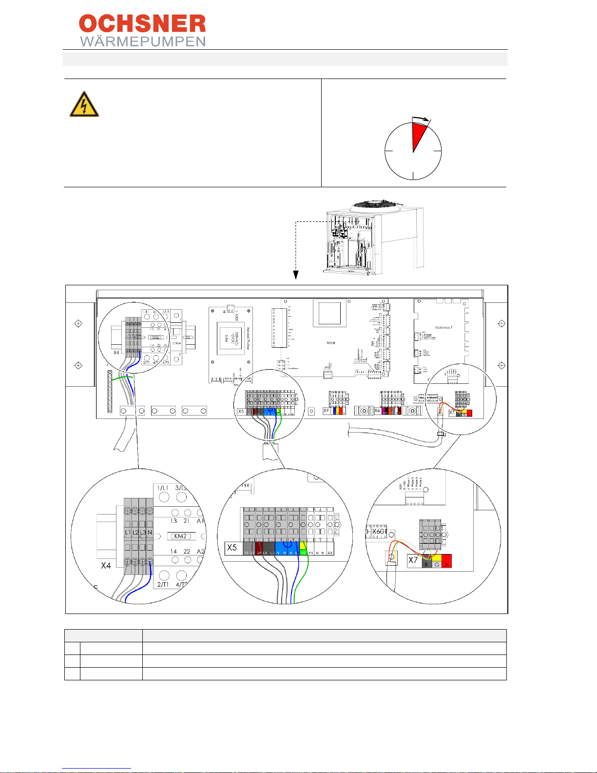
Outdoor unit wiring
CAUTION danger of death!
Prior to carrying out any work/repairs on the
outdoor unit, wait at least 4 minutes after
disconnecting the unit from the power supply, to
ensure all capacitors have been discharged.
From disconnection from power supply:
+4 minutes
Terminal
Description
X4
L1/L2/L3/N/PE
Compressor power supply (W4, to indoor unit)
X5
23/24/LS/N/PE
Control cable to indoor unit
X7
B/GND/A
Modbus connection to indoor unit
Figure 52: Outdoor unit wiring
4 minutes

BA_OCHSNER AIR EAGLE_414_717_V06_EN.docx Page 41 of 76
6.15 Wiring diagrams
EAGLE 717 with Golf-Midi indoor unit
A Main distributor
B Indoor unit control box
C Outdoor unit control
box
1 Compressor supply
(C16A across all poles)
2 Controller supply
(C13A)
3 Electric booster heater
supply
(B16A across all poles)
4 Option:
Supply for DHW
auxiliary heater for
anti-legionella function
5 Modbus cable
6 Control cable
7 Compressor supply
BA_OCHSNER AIR EAGLE_414_717_V06_EN.docx Page 42 of 76
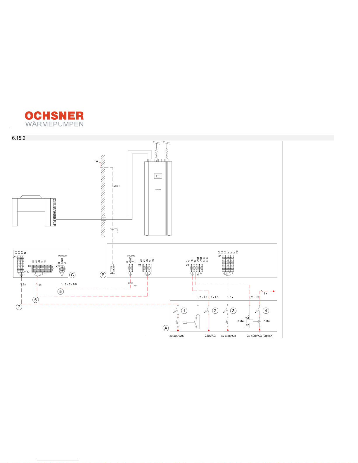
EAGLE 717 with T200 indoor unit
A
Main distributor
B Indoor unit control box
C Outdoor unit control
box
1 Compressor supply
(C16A across all
poles)
2 Controller supply
(C13A)
3 Electric booster heater
supply
(B16A across all
poles)
4 Option:
Supply for DHW
auxiliary heater for
anti-legionella function
5 Modbus cable
6 Control cable
7 Compressor supply

BA_OCHSNER AIR EAGLE_414_717_V06_EN.docx Page 43 of 76
EAGLE 414 with Golf-Midi indoor unit
A
Main distributor
B Indoor unit control box
C Outdoor unit control box
1 Compressor supply
(C20A)
2 Controller supply
(C13A)
3 Electric booster heater
supply
a: 3x 400 V (B16A across
all poles)
b: 1x 230 V (B40A)
3a
Booster heater with
3-phase power supply
3b
Booster heater with
single phase power supply
4 Option:
Supply for DHW auxiliary
heater for anti-legionella
function
5 Modbus cable
6 Control cable
7 Compressor supply
8 Option:
Mains switch for EAGLE
outdoor unit

BA_OCHSNER AIR EAGLE_414_717_V06_EN.docx Page 44 of 76
EAGLE 414 with T200 indoor unit
A
Main distributor
B Indoor unit control box
C Outdoor unit control box
1 Compressor supply
(C20A)
2 Controller supply
(C13A)
3 Electric booster heater supply
a: 3x 400 V (B16A across all
poles)
b: 1x 230 V (B40A)
3a
Booster heater with
3-phase power supply
3b
Booster heater with
single phase power supply
4 Option:
Supply for DHW auxiliary
heater for anti-legionella
function
5 Modbus cable
6 Control cable
7 Compressor supply
8 Option:
Mains switch for EAGLE outdoor unit
BA_OCHSNER AIR EAGLE_414_717_V06_EN.docx Page 45 of 76
7 Heating system
The heating water and system pressure should be
checked regularly by the system operator and
corrected in case of deviations (pressure too
high/low). The flow rates at the heat sink system
(WNA) are monitored by the integral flow sensor.
The specified system maintenance intervals and
system checks must also be observed.
If major modifications or pipe breakages require
draining and subsequent replacing of a large
proportion of the heating water, this should be
done in the presence of OCHSNER customer
service or by an authorised OCHSNER authorised
partner (see enclosed logbook). In the case of nonroutine refilling (e.g. after modifications or pipe
breakages), a current water assessment must be
prepared, and, on the basis of this, the heat sink
system must be refilled, with additives if required,
by the installer.
7.1 Quality of heating water
Use the correct fill water that is suitable for the
components of your heating system. We
recommend fill water prepared according to
Guideline VDI 2035-2.
A high pH value and low electrical conductivity in
the fill water will reduce to a minimum the risk of
corrosion to iron and copper materials, as long as
there is also low oxygen content. This will also
minimise scaling (calcification).
Fill water characteristics
pH value at 25°C
8.5-10
Electrical conductivity at
25°C
< 100 μS/cm
Oxygen content
< 0.05 mg/l
Chloride
< 30 mg/l
Unsuitable fill water can damage your
system due to scaling and corrosion. If
necessary, ensure that the fill water is
professionally softened and
demineralised.
7.2 Pressure maintaining system
For the operational reliability of your
system in defrosting or cooling mode, it
is important that the hydraulic safety
and pressure maintaining devices are
sufficiently sized and inspected annually
according to the relevant standards.
CAUTION
The closures provided are only for
transport. Replace them with suitable
plugs if the DHW flow or return is not
being used!
BA_OCHSNER AIR EAGLE_414_717_V06_EN.docx Page 46 of 76
8 Commissioning
8.1 Before starting
The heat pump has no separate ON/OFF switch. In
an emergency, the system must be shut down via
the specified circuit breaker. The circuit breaker
must be accessible so that an emergency
shutdown can be performed at any time.
Caution - risk to life
First-time start-up of electrical systems
is permitted only in the presence of a
qualified electrician.
Do not turn ON (or OFF) the power to the system,
until:
• Nobody can be put at risk
• All installation work on the heat pump is
completed
• All wiring is completed
• Voltages have been checked according to
the documentation
• The hydraulic system has been filled with
water
• The system has been fully vented
The supply voltage for the compressor must not
be turned on, until the refrigerant circuit and the
hydraulics have been filled with the correct
medium.
Once all conditions above have been checked and
met, the controller voltage of 230 VAC (fuse F1)
can be switched on for checking individual
functions.
Carefully check all sensors and their measurement
values for plausibility and all outputs used in your
hydraulic system for correct function.
CAUTION
Operating the heat pump with too little
or no refrigerant will damage the
appliance. Operating circulation
pumps without water in the system will
destroy the pump.
The heat pump must be commissioned by
OCHSNER customer service or an authorised
OCHSNER partner. The OCHSNER commissioning
guidelines apply. Operating the system without it
having been properly commissioned by factory
customer service will void all guarantee and
warranty rights.
8.2 Persons required on site
The electrician, installer and future system
maintainer or operator must be present during
commissioning for instruction.
Information for the system installer:
• The OCHSNER customer service engineer /
customer service partner makes the user
specific adjustments according to the
information in the system datasheet. If the
system installer is not present during
commissioning or if a fully completed system
datasheet is not available, the system is put
into operation using the control factory
settings. OCHSNER will accept no liability for
any faulty operation (heating curve too low,
bivalent point too high, etc.). Any claims
resulting from this will be charged to the
system installer.
• For the system to operate efficiently, it is
essential that hydraulic balancing is carried
out and the controller is adjusted according to
the system requirements.
• Special work, such as venting, electrical
connections, renewed instruction, etc., not
included in the scope of work provided by
OCHSNER will be charged separately.
BA_OCHSNER AIR EAGLE_414_717_V06_EN.docx Page 47 of 76
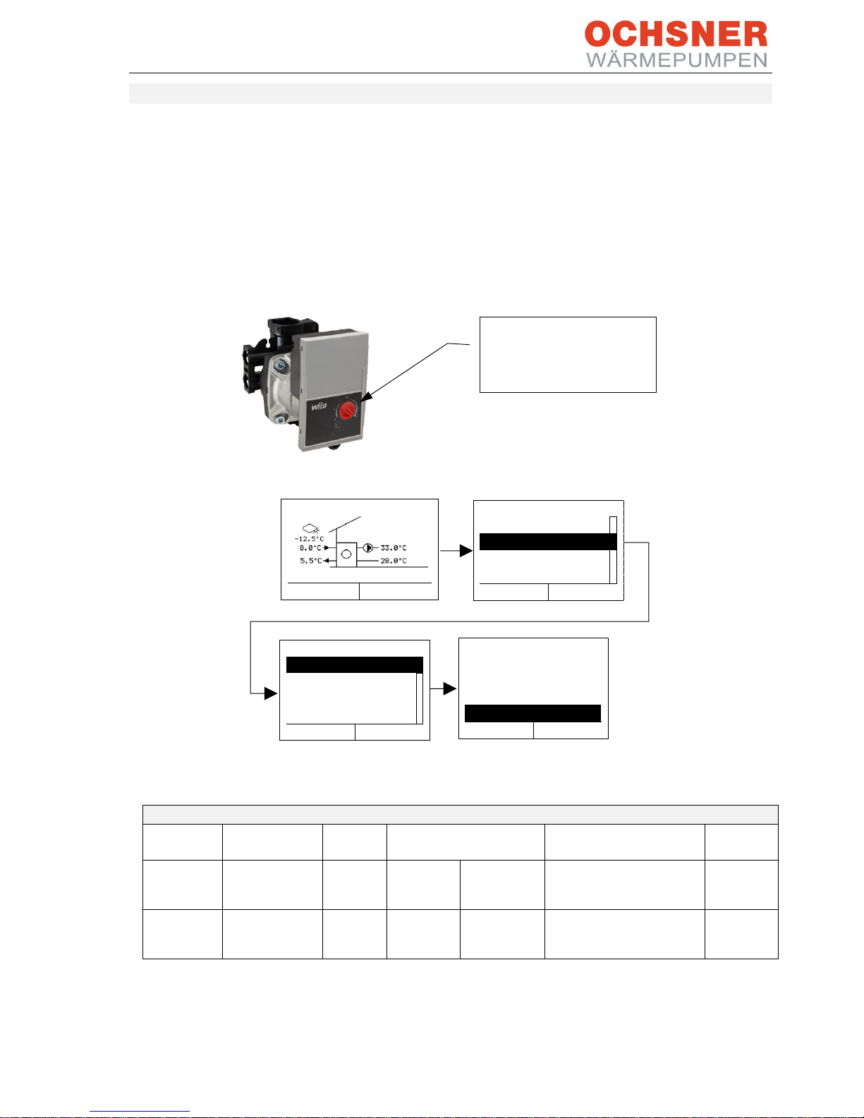
8.3 Setting the flow rate
The nominal flow rate must be ensured in each
operating mode (DHW charging, heating or
cooling mode via separate cooling/buffer tank,
etc.). The flow rate is measured via the installed
flow sensor and shown on the OTE controller
display. On the supplied circulation pumps, the
flow rate is adjusted via the adjusting screw.
To enable hydronic balancing according to the
relevant standards, in particular during combined
heating or heating/cooling and DHW heating
modes, the appropriate balancing valves must be
installed and the system regulated accordingly.
The measured flow rate is displayed on the heat
pump display and must correspond to the nominal
flow rate.
Figure 53: Setting the flow rate
Figure 54: Reading the flow rate
Heat consumption
Heat pumps
Circulation
pump
Item no.
Nominal flow rate,
heat sink
Internal
differential pressure
Residual
head
OCHSNER
AIR
EAGLE 717
PARA HPS
25/7.5 RKC
922586
1.8 m³/h
30 l/min
220 mbar
In DHW mode +30 mbar
380 mbar
(350 mbar)
OCHSNER
AIR
EAGLE 414
PARA HPS
25/7.5 RKC
922586
1.4 m³/h
23 l/min
160 mbar
In DHW mode +10 mbar
590 mbar
(580 mbar)
Table 3: Nominal flue rates
Adjust the flow rate by
turning the red adjusting
screw.
WAERMEPUMPE
Betriebswahl
Betriebsdaten
Einstellungen
Relaistest
ESC
ENTER
WAERMEPUMPE
ESC
ENTER
21-002
WAERMEPUMPE
Volumenstrom Wärmenut-
zung
27.4 l / min
ESC
ENTER
ESC
ENTER
23-010
Heizenergie MWh
0
23-003
Heizleistung
0
WAERMEPUMPE
21-002
Volumenstrom Wä
27
23-001
Heizenergie kWh
0
HEAT PUMP
HEAT PUMP
HEAT PUMP
Operation mode
Operating data
Settings
Relay test
Flow rate heat
Heating energy kWh
Heating energy MWh
Heating output
HEAT PUMP
Flow rate heat sink

BA_OCHSNER AIR EAGLE_414_717_V06_EN.docx Page 48 of 76
9 Operation
Figure 55: Operation
The main display shows current temperatures, the operating state and the date and time. The "operating
state" display provides information about the entire system. All heat generators and/or consumers are free
from faults.
9.1 Menus
The OCHNSER AIR EAGLE is operated via the
master operating panel on the heat pump indoor
unit. There are 2 buttons (A and B) as well as an
illuminated graphic display for showing the
functions.
Pressing the right-hand button (A) calls up the
main menu with a diagram of the heating system
is illustrated.
Each heat consumer (heating circuits, DHW
circuits) and each heat generator (heat pump,
electric booster heater, boiler etc.) has its own
menu and submenus.
Pressing button (B) takes you back one step (ESC).
You can also purchase a RoomTerminal with
touchscreen.
Figure 56: Operation
For more information on how to operate the
controller, see the current OTE operating manual
which is supplied with every heat pump.
OCHSNER OTE
MENU
Sa 21.010.2015
08:10
Heizbetrieb
Time Date
Outdoor
temperature
Operating status
Button B
one step back
(ESC)
DHW temperature
System
temperature
Button A
Menu selection
and confirmation
ENTER
WARMWASSERKREIS
WAERMEPUMPE
Hauptmenü
HEIZKREIS 1
HEIZKREIS 2
ESC
Button A
Button B

BA_OCHSNER AIR EAGLE_414_717_V06_EN.docx Page 49 of 76
9.2 Appliance function
Heating circuit
The heating circuits operate fully automatically
with weather compensation and summer/winter
changeover.
DHW
DHW heating is according to the default target
value. The efficiency of the system can be
increased with a DHW time program.
Anti-legionella function
To prevent legionella, the DHW has to be
periodically heated to a temperature of at least
60°C. The anti-legionella function is automatic and
can be controlled via a time program. Depending
on the system version, the electric booster heater
is activated.
Second heat generator
OCHNSER AIR EAGLE heat pumps are supplied
with an electric emergency/booster heater as
standard. The electric immersion heater is built
into the MFA module and is required to ensure the
operational reliability of your heating system.
Protect the supply voltage in the main distribution
box across all poles. The voltage is supplied via the
KM3 contactor and is automatically switched on
by the system.
Effect of the electric emergency/booster heater
in the heat pump flow:
• Mono energetic operation
The electric emergency/booster heater
guarantees heating mode and the provision of
high DHW temperatures when the bivalent
point is not reached.
• Emergency mode
Should the heat pump fail due to a fault, the
heating output is provided by the electric
emergency/booster heater.
For the operational reliability of your heating
system, ensure the power supply to the electric
booster heater at all times!
Screed drying program
In case of return temperatures <25°C (room
temperatures) the heat for drying has to be
provided by the electric emergency/booster
heater! At these low system temperatures the
heat for drying must not be provided by the heat
pump as the frost protection of the appliance can
no longer be guaranteed during the defrost cycle.
At the end of the drying out program, the electric
emergency/booster heater can be disconnected
as long as it is not required for the operation of the
appliance. Note that emergency operation is not
possible in the screed drying program.
9.3 System operation
Running costs
Depending on the residual building moisture,
increased running costs of up to 50% are to be
expected.
Flow temperatures
To ensure energy saving operation of the heat
pump, try to keep the heating flow temperature
(and also DHW temperatures) as low as possible.
For EAGLE heat pumps, the max. system
temperature should be limited to 60°C.
NOTE
Increasing the room temperature by
1°C results in an increase in
consumption of 5-7%.

BA_OCHSNER AIR EAGLE_414_717_V06_EN.docx Page 50 of 76
10 Troubleshooting
Let only trained specialist personnel carry out adjustments and troubleshooting! Standard settings for the
controller are made by customer service during commissioning. The operator and contracting partner is
responsible for additional corrections and program adjustments!
Fault/display
Cause
Solution
Heating system does
not heat up,
no fault
1. PSU shutdown
2. Energy transfer to the
heating circuits is
interrupted or too low
3. Power failure
4. DHW priority
Chick individual room controls, vent
heating circuit,
open valves,
check DHW circulation pump, increase
output level of the DHW circulation pump
Check fuses
Heat pump only
produces DHW but does
not heat or heats too
late
DHW target temperature is too
high
Check the DHW target temperature
Anti-legionella mode
Use time program
Install electric immersion heater for DHW
DHW circulation hydraulics
Reduce flow rate and use timer
DHW heat exchanger scaled up
Notify heating contractor, clean heat
exchanger, descale
DHW temperature not
reached or no longer
reached
Heat exchanger for DHW is too
small
Increase size of heat exchanger
Heat exchanger is scaled up
Descale heat exchanger
Sensor positioned incorrectly
Position correctly
Pipework too small
Install larger pipes
Faulty DHW sensor
replace
DHW charging pump faulty
replace
DHW charging pump output
level set too low
Set higher output levels
3-way switching valve faulty
replace
Heat pump runs
continually and yields
only low temperature;
traces of oil in the
appliance
Escaping refrigerant
refrigerant line leaking
Switch off heat pump,
notify customer service
Er.91
insufficient flow rate
The minimum flow rate at the
heat pump is not being reached.
insufficient system pressure,
Check pressure maintaining device, buffer
charging pump faulty,
diverter valve faulty
No hot water and
heating system remains
cold.
Power failure
Check cause!
Reset circuit breaker.
Table 4: Troubleshooting

BA_OCHSNER AIR EAGLE_414_717_V06_EN.docx Page 51 of 76
10.1 Error Codes OTE
Code
Log
file no.
Error designation
Possible cause / remedy
115 Er 01: DHW sensor faulty
Replace sensor
116 Er 10: Outside sensor faulty
Replace sensor
117 Er 14: Mixer sensor faulty
Replace sensor
124 Er 20: TWR sensor faulty
Replace sensor
120
Er 22: TWR/TPM shutdown sensor
faulty
Replace sensor
136 Er 23: TPV sensor faulty
Replace sensor
118 Er 24: Buffer sensor faulty
Replace sensor
114 Er 29: TWV sensor faulty
Replace sensor
11
11
Er 30: Phase monitor
Monitoring via starting current limiter KS01 (display of alarm type
via flashing sequence of red LED)
134 Er 32: THG sensor faulty
Replace sensor
138 Er 33: High pressure sensor faulty
Check sensor
137 Er 34: Low pressure sensor faulty
Check sensor
5 5 Er 36: High pressure
Insufficient heat distribution, circulation pump faulty, valve closed
/ air in system, check hydraulics
18
18
Er 37: Low pressure
Lack of source energy, lack of refrigerant, check expansion valve
of refrigerant circuit (OCHSNER)
16
16
Er 38: Hot gas
Expansion valve, lack of refrigerant, target value too high, check
refrigerant circuit (OCHSNER)
10
10
Er 39: Compressor motor
protection
Overload, source temperature too high,
check: compressor in refrigerant circuit (OCHSNER)
8 8 Er 42: Heat sink frost protection
Insufficient heat distribution, circulation pump faulty, valve closed
/air in system, check buffer pump or hydraulics
Er 46: TSG sensor faulty
Replace sensor
9 9 Er 47: Defrost fault
Insufficient defrosting energy, check evaporator / sensor, check
booster heater, check refrigerant circuit (OCHSNER)
129
129
Er 48: TQE sensor faulty
Replace sensor
130
130
Er 49: TQA sensor faulty
Replace sensor
12
12
Er 50: Expansion valve
Check function of EEV (OCHSNER)
1 1 Er 56: Heat source flow rate
insufficient flow rate, lack of source energy, check source
pump/filter
2 2 Er 57: Heat source frost protection
Lack of source energy, source temperature too low: check heat
source, check source pump/filter, clean water filter, groundwater
pump faulty
3
3
Er 58: Heat source motor
protection
Overload, check motor protection, check wiring to motor/fan, TK
143
143
Er 59: TWV + TWR sensor break
Check sensor
144
144
Er 60: TQA + TQE sensor break
Check sensor
42
42
Er 71: Bus fault, room remote
control
Check eBus wiring
30
30
Er 80: HG 1 address
Check addressing
31
31
Er 81: HG 2 address
Check addressing
32
32
Er 82: HG 3 address
Check addressing
33
33
Er 83: HG 4 address
Check addressing
34
34
Er 84: HG 5 address
Check addressing
35
35
Er 85: HG 6 address
Check addressing
36
36
Er 86: HG 7 address
Check addressing
37
37
Er 87: HG 8 address
Check addressing
20
20
Er 91: Heat sink flow rate
insufficient water pressure, circulation pump faulty, valve closed /
air in system, check hydraulics
21
21
Er 90: Overheating
Check refrigerant circuit (OCHSNER)
98
98
Er 98: Electric immersion heater
running as sole heat generator!
Check setting for operating mode of heat pump
104
104
Er104: Heat pump sum fault
Only for ELW or AIR EAGLE – OCHSNER customer service
108
108
Er108: Outdoor unit
communication fault
Only for ELW - check wiring
109
109
Er109: Compressor overheating
Only for ELW – automatic acknowledgement
100
100
Er200: Condensation temperature
too low
Check refrigerant circuit (OCHSNER)

BA_OCHSNER AIR EAGLE_414_717_V06_EN.docx Page 52 of 76
Code
Log file
no.
Error designation
Possible cause / remedy
102
102
Er 201: Evaporation
temperature too low
Check refrigerant circuit (OCHSNER)
103
103
Er 202: Evaporation
temperature too high
Check refrigerant circuit (OCHSNER)
240
240
Er 240: OTE does not detect a
Modbus PCB
Only for AIR EAGLE – OCHSNER customer service
241
241
Er 241: Modbus
communication error
Only for AIR EAGLE – check wiring of Modbus line between indoor
and outdoor units.
Otherwise, OCHSNER customer service
242
242
Er 242: CAN Bus
communication error
Only for AIR EAGLE – check wiring of CAN bus line and Modbus
line (possible consequential fault of Er241)
Otherwise, OCHSNER customer service
Table 5: OTE Error Codes
10.2 Dealing with faults
Various Faults "Er. XXX" as well as troubleshooting
options are displayed on the OTE controller. In the
event of a fault, your installer is your first point of
contact. The installer must be notified of the faults
and can provide you with valuable information for
troubleshooting. Your installer knows your
hydraulic system and how it operates. The causes
of faults can be found in the settings or hydraulics.
If it is nevertheless not possible to identify or
rectify the causes, OCHSNER customer service is
available to help.
10.3 Rectifying minor causes
independently
Your heat pump is extremely maintenance
friendly. To operate the heat pump efficiently and
without faults, you can remedy minor causes
simply on site.
Before you start:
• Disconnect the system from the power supply,
• Safeguard against unauthorised reconnection,
• Ensure it is voltage-free,
• Before carrying out any further work, wait at
least 4 minutes after switching off the power
supply!
• Do not reach into the fan!
• Do not remove the protective grille from the
fan.
Ensure that:
• the evaporator is free from leaves and twigs or
other foreign bodies.
• condensate can drain away.
• there is sufficient water in the heating circuit.
• the system pressure is adequate.
You can optimise your system by checking the
heating circuit and DHW heating settings. Keep
records and only adjust 1-2 settings in a day.
10.4 Cleaning and care
Protect the appliance from dust and dirt during
building work. A large plastic bag is provided for
this purpose. A damp cloth is sufficient to look
after plastic and sheet metal parts. Do not use any
abrasive or corrosive cleaning materials.
Ensure that no ice is formed, especially around
walking surfaces and entrances around the
outdoor unit.

BA_OCHSNER AIR EAGLE_414_717_V06_EN.docx Page 53 of 76
11 Maintenance
For maintenance work, disconnect the
power supply to the indoor unit and
the outdoor unit of your heat pump.
NOTE
Ensure that the refrigerant circuit of
your heat pump is tested for leaks once
a year (in acc. with Regulation
(EU) no. 517/2014).
- Ensure year-round access to
soldered joints in the refrigerant
circuit.
- Document the results of the
leakage test in the system test
report.
We recommend arranging for an inspection and if
necessary a service on the heat pump to be
conducted once a year. We draw your attention to
the fact that statutory regulations require regular
testing of heating systems by the system user.
The refrigerants used in OCHSNER heat pumps are
non-flammable, non-toxic and ozone neutral.
However, heat pumps are refrigeration
equipment and are subject to the provisions of the
F-gas Regulations (Regulation (EU) no. 517/2014).
OCHSNER Customer Service will be pleased to help
in carrying out maintenance and testing, in
particular as required by the F-gas Regulations. For
more information, see www.ochsner.com.
We recommend testing the heating water system
pressure and correcting it if necessary (pressure
too high/low).
We recommend adjusting the pre-charge pressure
in the diaphragm expansion vessel (DEV) on the
system accordingly (system height).
We recommend monitoring the flow rate of the
heat sink system (WNA) and if necessary the heat
source system (WQA) using the flow meters
specified by OCHSNER.
We recommend that when non-routine work
takes place requiring refilling (e.g. system
alteration or pipe breakage), a current water
assessment be prepared and the heat sink system
be refilled on the basis of this.
11.1 Customer service
Once a date has been agreed with or requested
from OCHSNER customer service, repairs to your
heat pump are carried out by a trained customer
service specialist on site. In order for service work
to be carried out, the accessibility of the heat
pump and auxiliary equipment must be ensured at
all times!
Please observe the minimum
clearances when installing the
equipment.
Customer Service hotline for Austria:
Tel: +43 (0) 504245 – 499
Email: kundendienst@ochsner.at
Customer Service hotline for Germany:
Tel: +49 (0) 69 256694 - 495
Email: kundendienst@ochsner.de
Customer Service hotline for Switzerland:
Tel: +41 (0) 800 100 911
Email: kontakt@ochsner.com

BA_OCHSNER AIR EAGLE_414_717_V06_EN.docx Page 54 of 76
11.2 Maintenance contract
OCHSNER offers a wide range of maintenance
contracts. For more information, see
www.ochsner.com.
Benefits of a maintenance contract
- Annual inspections fulfil the statutory
requirements of the F-gas regulations.
- A correctly performed service not only helps
to save energy but also protects the
environment.
- In addition, correct care of the heating system
is necessary to ensure many years of service
life and indeed to extend the service life of the
system.
- For the system user, this reduces the risk of
system failure.
For more information about customer service and
the scope of the maintenance contracts, see
www.ochsner.com.

BA_OCHSNER AIR EAGLE_414_717_V06_EN.docx Page 55 of 76
12 Environment and recycling
12.1 Disposal of transport packaging
The transport packaging for the heat pump
consists of recyclable raw materials. Waste
transport packaging should be sorted and
recycled. Leave disposal of transport packaging to
the authorised contractor who has installed the
appliance.
12.2 Decommissioning
Before decommissioning, all 'live'
connections should be isolated from
the power supply by an authorised
contractor.
Appliances with refrigerant should only be
decommissioned by an authorised contractor
(refrigeration/air conditioning/heating). The
refrigerant should be emptied/removed and
recycled or disposed of by the contractor.
Improper disposal of refrigerant can
cause significant environmental
damage and carries a penalty!
12.3 Disposal of the appliance
The old heat pump should be disposed
of at regional waste collection facilities
in accordance with applicable regional
environmental regulations and standards.
Parts of the heat pump must not be disposed
of as domestic waste!

BA_OCHSNER AIR EAGLE_414_717_V06_EN.docx Page 56 of 76
13 Specification
13.1 Data table (with Golf-Midi indoor unit)
APPLIANCE DATA:
EAGLE 717
EAGLE 414
Dimensions of outdoor unit HxWxD
[mm]
1260 x 1480 x 960
Dimensions of indoor unit HxWxD
[mm]
1150 x 400 x 650
Hydraulic connection
[inch]
1" fem.
Weight of outdoor unit
[kg]
200
Weight of indoor unit
[kg]
70
Casing colour
outdoor
RAL 7016, anthracite grey
HEATING MODE PERFORMANCE FIGURES:
EAGLE 717
EAGLE 414
Standard point A7/W35
Heating output range
[kW]
6.7 - 8.3
3.5 - 10.6
Total heating output / power consumption EN 14511
[kW]
7.1 / 1.5
6.0 / 1.3
COP EN 14511
4.8
4.5
Standard point A2/W35
Heating output range
[kW]
6.0 - 10.4
3.1 - 10.2
Total heating output / power consumption EN 14511
[kW]
7.1 / 1.7
5.5 / 1.4
COP EN 14511
4.2
4
Standard point A7/W55
Heating output range
[kW]
6.6 - 8.6
3.9 - 11.0
Total heating output / power consumption EN 14511
[kW]
8.6 / 2.7
6.4 / 2.1
COP EN 14511
3.3
3.1
Standard point A-7/W34
Heating output range
[kW]
5.2 - 14.1
2.6 - 8.6
Total heating output / power consumption EN 14825
[kW]
12.8 / 4.1
7.8 / 2.7
COP EN 14825
3.1
2.9
SPECIFICATION:
EAGLE 717
EAGLE 414
Outdoor unit, controller (phases/nominal voltage/frequency)
[~]/[V]/[Hz]
3/400/50
1/230/50
Fuse protection (tripping curve "C")
[A]
16
20
Max. operating current
[A]
16
20
Max. starting current, compressor
[A]
< 10
< 10
Sound power level/sound pressure level at 3 m indoor unit
[dBA]
< 50/32
< 50/32
Electric auxiliary heater:
EAGLE 717
EAGLE 414
Phases/nominal voltage/frequency
[~]/[V]/[Hz]
3/400/50
1/230/50
3/400/50
Max. output
[kW]
8.8
8.8
8.8
Max. operating current
[A]
16
40
16
COOLING MODE:
EAGLE 717
EAGLE 414
Limits of use (outdoor temperature)
[°C]
15 - 40
15 - 40
Table 6: Specification (part 1)

BA_OCHSNER AIR EAGLE_414_717_V06_EN.docx Page 57 of 76
CONDENSER:
EAGLE 717
EAGLE 414
Type Plate heat exchanger
Material Stainless steel 1.4301
Number
[pce] 1 1
Max. refrigerant operating pressure
[bar]
45
45
Max. heat transfer medium operating pressure
[bar] 3 3
Heat transfer medium temperature differential
[K] 5 5
Application range
[°C]
65
65
Heat transfer medium
Water
Water
Heat exchanger test pressure
[bar]
78
78
Heat transfer medium flow rate
[m³/h]
1.8
1.4
Internal pressure differential
[mbar]
220
160
Flow meter FM standard
internal
Circulation pump heat sink WNA
internal
Residual head I WNA external, incl. FM
[mbar]
380
590
REFRIGERANT CIRCUIT
EAGLE 717
EAGLE 414
No. of refrigerant circuits
[pce] 1 1
Refrigerant
R410A
R410A
Defrost technology
Hot gas
Hot gas
Refrigerant charge (from-to)
[kg]
5.5 - 7.3
8 - 9.2
COMPRESSOR:
EAGLE 717
EAGLE 414
Type Scroll
Scroll
Number
[pce] 1 1
Output levels
Infinitely variable
Infinitely variable
Speed
[rpm]
2100-7000
2100-7000
Voltage/frequency
[V]/[Hz]
400/50
230/50
FAN: EAGLE 717
EAGLE 414
Type
axial
Number
[pce]
1
Voltage/frequency
[V]/[Hz]
230
Power consumption
[W]
230
EVAPORATOR:
EAGLE 717
EAGLE 414
Unit type
Type
Finned tube
Number
[pce]
1
Air flow rate
[m³/h]
4000
Sound pressure level at 10 m /Sound power level at standard
conditions A7/W55
[dBA]
29/57
Table 7: Specification (part 2)

BA_OCHSNER AIR EAGLE_414_717_V06_EN.docx Page 58 of 76
13.2 Data table (T200 indoor unit)
APPLIANCE DATA:
Height
mm
1931
Width
mm
680
Depth
mm
855
Tilt height
mm
2121
Empty weight
kg
203
Filled weight
kg
471
IP rating IP 20
Tank thermal insulation
mm
90
Heat exchanger area
m²
3.3
Heat exchanger capacity
l
21
DHW TANK:
Nominal capacity
l
168
Material Enamelled steel
Energy efficiency class
C
Standby losses W 65
Tank volume l 189
Standby power consumption at 65°C
kWh/24h
1.6
Standby power consumption at 65°C
W
79
Area of smooth tube coil
m²
3.2
Max. operating pressure
bar
10
Test pressure
bar
15
Draw-off rate of DHW tank
l/min
25
BUFFER TANK:
Nominal capacity
l
100
Material Steel
Max. operating pressure
bar
3
Test pressure
bar
4.5
Max. permissible temperature
°C
95
Water hardness
°dH
≤3
pH value (with aluminium compounds)
8.0-8.5
pH value (without aluminium compounds)
8.0-10.0
Conductivity (softening)
µS/cm
<1000
Conductivity (desalinated)
µS/cm
20-100
Chloride
mg/l
<30
Oxygen 8-12 weeks after filling (softening)
mg/l
<0.02
Oxygen 8-12 weeks after filling (desalination)
mg/l
<0.1
Max. power consumption of charging pump
W
72
Max. power consumption of heating circuit pump
W
72
CONNECTION:
Connections on the heating side
inch
1" union nut
Cold water connection
inch
1" union nut
DHW connection
inch
1" union nut
DHW circulation connection
mm
12
Table 8: T200 Specification

BA_OCHSNER AIR EAGLE_414_717_V06_EN.docx Page 59 of 76
13.3 Pressure drop
Heat consumption
Heat
pumps
Circulation
pump
Item no.
Nominal flow rate, heat
sink
Internal
differential pressure
Residual
head
OCHSNER AIR
EAGLE 717
PARA HPS
25/7.5 RKC
922586
1.8m³/h
30 l/min
220 mbar
In DHW mode +30 mbar
380 mbar
(350 mbar)
OCHSNER AIR
EAGLE 414
PARA HPS
25/7.5 RKC
922586
1.4 m³/h
23 l/min
160 mbar
In DHW mode +10 mbar
590 mbar
(580 mbar)
Table 9: Pressure drop
13.4 Pump curves
Figure 57: Pump curve
13.5 Limits of use
Flow temperature
Heat pump
Maximum design flow temperature
Outdoor temperature
65°C
53°C
60°C
-25°C
-4°C
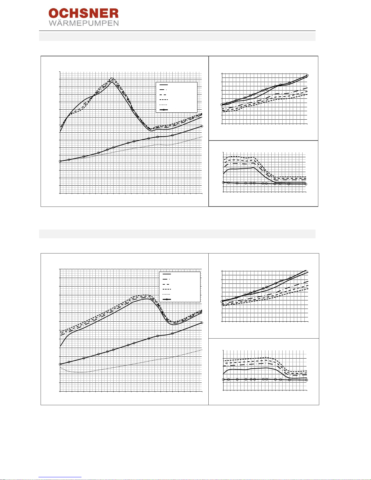
BA_OCHSNER AIR EAGLE_414_717_V06_EN.docx Page 60 of 76
13.6 Performance diagrams EAGLE 717
Figure 58: Performance diagrams EAGLE 717
13.7 Performance diagrams EAGLE 414
Figure 59: Performance diagrams EAGLE 414
1) Performance figures to EN 14511 - ∆T 5K
2) Performance figures with a component tolerance of ± 10%
3) CAUTION! During sizing, ensure the electric immersion heater, if installed, is adequately sized.
0
1
2
3
4
5
6
7
8
9
10
11
12
13
14
15
16
-23 -21 -19 -17 -15 -13 -11 -9 -7 -5 -3 -1 1 3 5 7 9 11 13 15 17 19 21 23 25
Heizleistung [kW]
Lufttemperatur [°C]
Leistungskurven Eagle 717
35°C max. Leistung
45°C max. Leistung
50°C max. Leistung
55°C max. Leistung
35°C min. Leistung
35°C Teillast
0
1
2
3
4
5
6
-23-21-19-17-15-13-11-9 -7 -5 -3 -1 1 3 5 7 9 1113151719212325
COP
Lufttemperatur [°C]
Eagle 717
0
1
2
3
4
5
6
7
8
-23-21-19-17-15-13-11-9 -7 -5 -3 -1 1 3 5 7 9 1113151719212325
Leistungsaufnahme [kW]
Lufttemperatur [°C]
Eagle 717
Heating output [kW]
Air temperature [°C]
Air temperature [°C]
Power consumption [kW]
Air temperature [°C]
0
1
2
3
4
5
6
7
8
9
10
11
12
13
14
-23 -21 -19 -17 -15 -13 -11 -9 -7 -5 -3 -1 1 3 5 7 9 11 13 15 17 19 21 23 25
Heizleistung [kW]
Lufttemperatur [°C]
Leistungskurven Eagle 414
35°C max. Leistung
45°C max. Leistung
50°C max. Leistung
55°C max. Leistung
35°C min. Leistung
35°C Teillast
0
1
2
3
4
5
6
-23-21-19-17-15-13-11-9 -7 -5 -3 -1 1 3 5 7 9 1113151719212325
COP
Lufttemperatur [°C]
Eagle 414
0
1
2
3
4
5
-23-21-19-17-15-13-11-9 -7 -5 -3 -1 1 3 5 7 9 1113151719212325
Leistungsaufnahme [kW]
Lufttemperatur [°C]
Eagle 414
Heating output [kW]
Air temperature [°C]
Air temperature [°C]
Air temperature [°C]
max. output
max. output
max. output
max. output
min. output
Partial load
max. output
max. output
max. output
max. output
min. output
Partial load
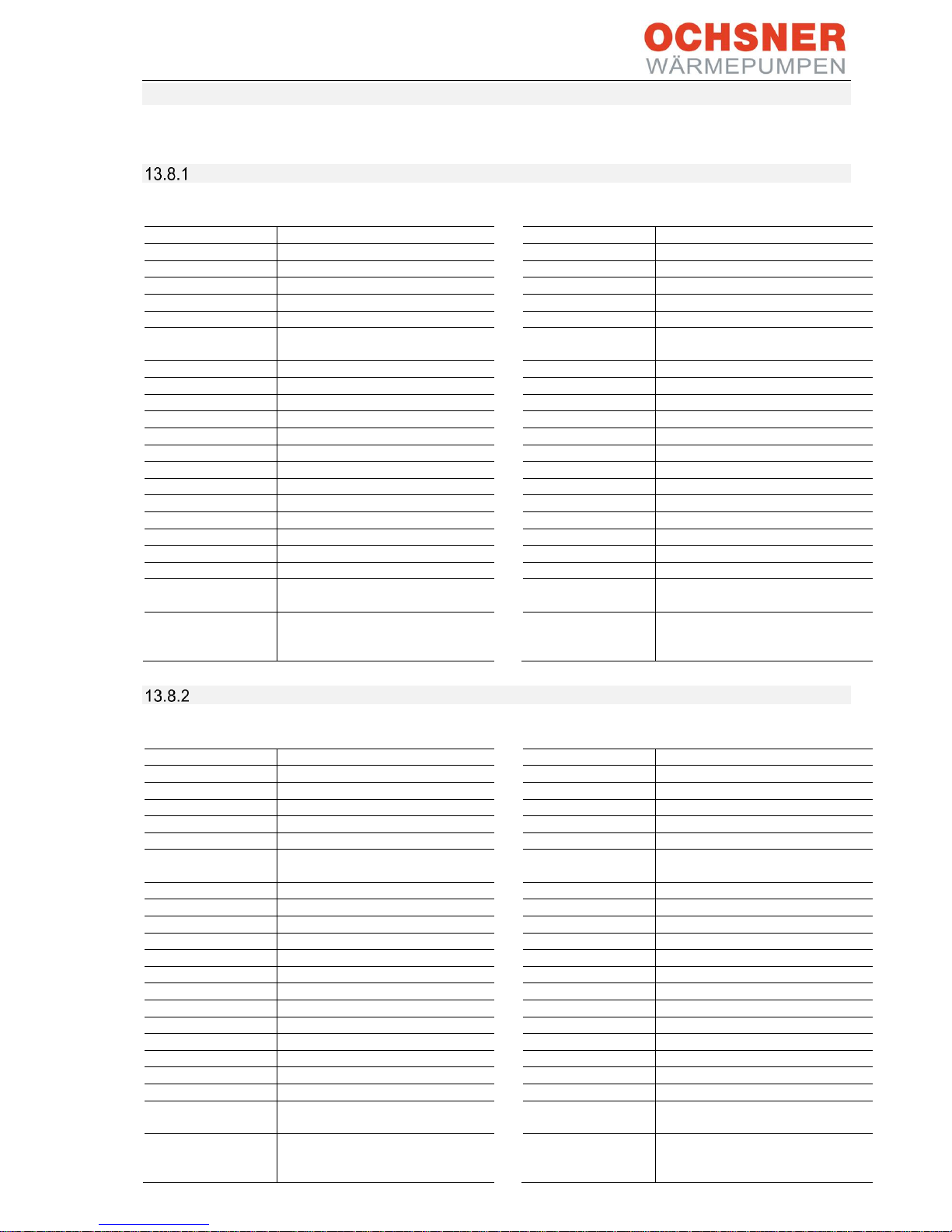
BA_OCHSNER AIR EAGLE_414_717_V06_EN.docx Page 61 of 76
13.8 Details of energy consumption
Product data conform to EU regulations on the Directive for Ecodesign of Energy Related Devices.
AIR EAGLE 414
OCHSNER AIR EAGLE 414
LOW TEMPERATURE
35°C
A++ Colder
Medium
Warmer
ηs 141
161
191
Energy consumption
[kWh]
7273
5177
2641
P rated
[kW]
10
10
9
SCOP
[-]
3.6
4.1
4.85
MEDIUM
TEMPERATURE
55°C
A++ Colder
Medium
Warmer
ηs 118
132
152
Energy consumption
[kWh]
9081
6197
3452
P rated
[kW]
11
10
10
SCOP
[-]
3.02
3.51
3.87
DHW
SP300
A Colder
Medium
Warmer
ηWH 87
95
110
Energy consumption
[kWh]
1638
1497
1299
Draw-off profile
XL
Tank losses
[W] 94
indoor
outdoor
Sound power level
[dBA] - 57.0
Controller class with
room remote control
VI
Controller
contribution [%]
4
Controller class
without room remote
control
II
Controller
contribution [%]
2
OCHSNER AIR EAGLE 414 with T200
LOW TEMPERATURE
35°C
A++ Colder
Medium
Warmer
ηs 141
161
191
Energy consumption
[kWh]
7273
5177
2641
P rated
[kW]
10
10
9
SCOP
[-]
3.6
4.1
4.85
MEDIUM
TEMPERATURE
55°C
A++ Colder
Medium
Warmer
ηs 118
132
152
Energy consumption
[kWh]
9081
6197
3452
P rated
[kW]
11
10
10
SCOP
[-]
3.02
3.51
3.87
DHW
T200
A Colder
Medium
Warmer
ηWH 84
92
106
Energy consumption
[kWh]
1001
915
794
Draw-off profile
L
Tank losses
[W] 79
indoor
outdoor
Sound power level
[dBA] - 57.0
Controller class with
room remote control
VI
Controller
contribution [%]
4
Controller class
without room remote
control
II
Controller
contribution [%]
2
AIR EAGLE 717
OCHSNER AIR EAGLE 717
LOW TEMPERATURE
35°C
A++ Colder
Medium
Warmer
ηs 164
174
208
Energy consumption
[kWh]
8466
7948
2949
P rated
[kW]
14
17
11
SCOP
[-]
4.18
4.42
5.28
MEDIUM
TEMPERATURE
55°C
A++ Colder
Medium
Warmer
ηs 133
141
177
Energy consumption
[kWh]
10081
9757
3622
P rated
[kW]
14
17
11
SCOP
[-]
3.4
3.71
4.49
DHW
SP300
A Colder
Medium
Warmer
ηWH 91
100
115
Energy consumption
[kWh]
1566
1431
1242
Draw-off profile
XL
Tank losses
[W] 94
indoor
outdoor
Sound power level
[dBA] - 57.0
Controller class with
room remote control
VI
Controller
contribution [%]
4
Controller class
without room remote
control
II
Controller
contribution [%]
2
OCHSNER AIR EAGLE 717 with T200
LOW TEMPERATURE
35°C
A++ Colder
Medium
Warmer
ηs 164
174
208
Energy consumption
[kWh]
8466
7948
2949
P rated
[kW]
14
17
11
SCOP
[-]
4.18
4.42
5.28
MEDIUM
TEMPERATURE
55°C
A++ Colder
Medium
Warmer
ηs 133
141
177
Energy consumption
[kWh]
10081
9757
3622
P rated
[kW]
14
17
11
SCOP
[-]
3.4
3.71
4.49
DHW
T200
A Colder
Medium
Warmer
ηWH 88
96
110
Energy consumption
[kWh]
957
875
759
Draw-off profile
L
Tank losses
[W] 79
indoor
outdoor
Sound power level
[dBA] - 57.0
Controller class with
room remote control
VI
Controller
contribution [%]
4
Controller class
without room remote
control
II
Controller
contribution [%]
2

BA_OCHSNER AIR EAGLE_414_717_V06_EN.docx Page 62 of 76
13.9 Electrical wiring diagrams EAGLE 717

BA_OCHSNER AIR EAGLE_414_717_V06_EN.docx Page 63 of 76

BA_OCHSNER AIR EAGLE_414_717_V06_EN.docx Page 64 of 76

BA_OCHSNER AIR EAGLE_414_717_V06_EN.docx Page 65 of 76

BA_OCHSNER AIR EAGLE_414_717_V06_EN.docx Page 66 of 76

BA_OCHSNER AIR EAGLE_414_717_V06_EN.docx Page 67 of 76
13.10 Electrical wiring diagrams EAGLE 414

BA_OCHSNER AIR EAGLE_414_717_V06_EN.docx Page 68 of 76

BA_OCHSNER AIR EAGLE_414_717_V06_EN.docx Page 69 of 76
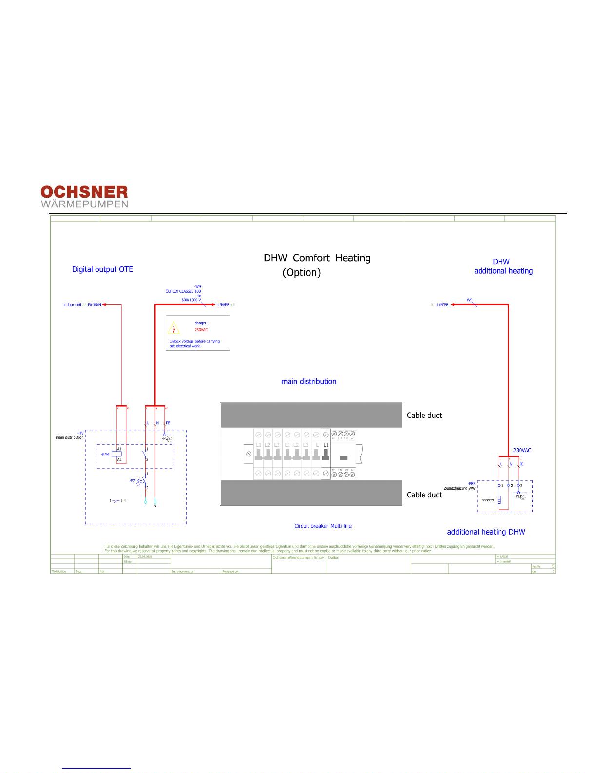
BA_OCHSNER AIR EAGLE_414_717_V06_EN.docx Page 70 of 76

BA_OCHSNER AIR EAGLE_414_717_V06_EN.docx Page 71 of 76

BA_OCHSNER AIR EAGLE_414_717_V06_EN.docx Page 72 of 76
14 List of figures
Figure 1: System overview............................................ 6
Figure 2: EAGLE outdoor unit ....................................... 7
Figure 3: Outdoor unit minimum clearances (in mm) .... 8
Figure 4: Outdoor unit dimensions (in mm) ................... 8
Figure 5: Outdoor unit main components .................... 10
Figure 6: Outdoor unit conduits ................................... 10
Figure 7: EAGLE outdoor unit (view from below), fixing
holes in the outdoor unit legs (dimensions in mm) ...... 11
Figure 8: Strip foundation (dimensions in mm) ........... 12
Figure 9: Spot foundation (dimensions in mm) ........... 12
Figure 10: Installation on concrete plinth (dimensions in
mm) ............................................................................ 13
Figure 11: EAGLE outdoor unit secured with structure-
borne noise attenuating fixings ................................... 14
Figure 12: Flat roof installation of EAGLE outdoor unit
(dimensions in mm) .................................................... 14
Figure 13: Indoor unit detailed view ............................ 15
Figure 14: View from above ........................................ 16
Figure 15: Minimum wall clearances ........................... 16
Figure 16: Indoor unit dimensions ............................... 17
Figure 17: Indoor unit tilt height .................................. 17
Figure 18: Indoor unit connection dimensions ........ 17
Figure 19: Indoor unit air vent valve ............................ 18
Figure 20: Draining and filling detailed view................ 18
Figure 21: T200 hydraulic schematic ...................... 19
Figure 22: Main components in T200 indoor unit ........ 20
Figure 23: Minimum clearances (in mm) ................ 21
Figure 24: Dimensions (in mm) ................................... 21
Figure 25: Hydraulic connections and labels, T200
refrigeration 22
Figure 26: Removing the fixing screw..................... 23
Figure 27: Pull the sensor from the buffer tank. ...... 23
Figure 28: Undoing the plug-in connectors ............. 23
Figure 29: Removing the hydraulic hoses .............. 24
Figure 30: Undoing the connecting screws............. 24
Figure 31: Separating the appliance sections 1 ......24
Figure 32: Separating the appliance sections 2 ......24
Figure 33: Setting down the T200 top section ........24
Figure 34: Assembling the appliance sections 1 .....25
Figure 35: Positioning aid ....................................... 25
Figure 36: Assembling the appliance sections 2 .....25
Figure 37: Drain hose, safety valve ........................26
Figure 38: Filling the heating system ......................27
Figure 39: Draining the buffer tank .........................29
Figure 40: Draining the DHW tank .......................... 29
Figure 41: T200 DHW tank sacrificial anode ..........29
Figure 42: Max. height difference ................................31
Figure 43: Oil lift bends ...............................................31
Figure 44: Conduit to house (dimensions in mm) ........31
Figure 45: Power supply .............................................33
Figure 46: PSU signal contact .....................................34
Figure 47: Pipe marking in the heat pump indoor unit .35
Figure 48: Wiring overview ..........................................36
Figure 49: T200 electrical connection .....................38
Figure 50: T200 indoor unit cable entry ......................38
Figure 51: T200 indoor unit connection terminals .......39
Figure 52: Outdoor unit wiring .....................................40
Figure 53: Setting the flow rate ...................................47
Figure 54: Reading the flow rate .................................47
Figure 55: Operation ...................................................48
Figure 56: Operation ...................................................48
Figure 57: Pump curve ................................................59
Figure 58: Performance diagrams EAGLE 717 ...........60
Figure 59: Performance diagrams EAGLE 414 ...........60
15 List of tables
Table 1: Cable selection ............................................. 33
Table 2: Wiring diagram .............................................. 36
Table 3: Nominal flue rates ......................................... 47
Table 4: Troubleshooting ............................................ 50
Table 5: OTE Error Codes .......................................... 52
Table 6: Specification (part 1) ..................................... 56
Table 7: Specification (part 2) .....................................57
Table 8: T200 Specification .........................................58
Table 9: Pressure drop................................................59

BA_OCHSNER AIR EAGLE_414_717_V06_EN.docx Page 73 of 76
16 Declaration of conformity

BA_OCHSNER AIR EAGLE_414_717_V06_EN.docx Page 74 of 76

BA_OCHSNER AIR EAGLE_414_717_V06_EN.docx Page 75 of 76
BA_OCHSNER AIR EAGLE_414_717_V06_EN.docx Page 76 of 76
Subject to technical modifications!
This manual describes appliances that are not always standard items. There may therefore be differences to your specific
heat pump.
System installer
Company ………………………………………..................................................................................................................
Address .....………………………………..........................................................................................................................
..………………………………………................................................................................................................................
Tel. ………………..........................................................................................................................................................
Service engineer ………………...................................................................................................................................
OCHSNER
Wärmepumpen GmbH Austria
(Commercial register)
Krackowizerstraße 4
A-4020 Linz
kontakt@ochsner.at
www.ochsner.com
OCHSNER
Wärmepumpen GmbH Germany
D-60314 Frankfurt a. M.
Riederhofstraße 27
Hotline for system partners: +49 (0) 1805 832840
Customer service hotline: +49 (0) 69 256694-495
kontakt@ochsner.de
www.ochsner.com
OCHSNER
Wärmepumpen GmbH Schweiz
CH-8001 Zürich
Uraniastrasse 18
Customer service hotline: +41 (0) 800 100911
kontakt@ochsner.com
www.ochsner.com
Head Office/Factory
Ochsner-Strasse 1
A-3350 Haag
Hotline for system partners: +43 (0) 820 201020
Customer service hotline: +43 (0) 5 04245-499
kontakt@ochsner.at
www.ochsner.com
OCHSNER East
PL 31-302 Kraków,
ul. Pod Fortem Nr. 19
Tel: +48 (0)12 4214527
kontakt@ochsner.pl
www.ochsner.pl
 Loading...