


HIGH EFFICIENCY AIR/WATER HEAT PUMPS
OPERATING AND INSTALLATION
MANUAL
AIR 7
►
AI R 11
►
AIR 18
►
AIR 23
►
AIR 29
►
AIR 41
►


CONTENTS
PLEASE NOTE
OPERATION
1. Information on documentation 4
1.1 Safety information 4
1.1.1 Arrangement of safety information 4
1.1.2 Symbols and possible dangers 4
1.1.3 Keywords 4
1.2 Other symbols 5
1.3 Units of measurement 5
1.4 Specied performance data 5
2. Safety 5
2.1 Intended use 5
2.2 General safety information 5
3. Appliance description 6
3.1 Functionality 6
3.2 Appliance components 6
3.2.1 Indoor unit 6
3.2.2 Outdoor unit 7
3.2.3 Heat pump control unit 7
3.3 Name plate 7
4. Activating settings 8
4.1 Operating costs 8
4.1.1 Flow temperatures 8
4.1. 2 Ventilation 8
4.1. 3 Heating setback program 9
5. Maintenance and care 9
6. Problem solving 9
INSTALLATION
7. Safety 10
7.1 General safety information 10
7. 2 Regulations, codes and standards 10
8. Appliance description 10
8.1 Standard delivery 10
8.2 Hydraulic variants of the indoor unit 11
9. Preparing to install the appliance 13
9.1 Indoor unit installation location 13
9.1.1 Keep minimum clearances 13
9.2 Outdoor unit installation location 13
9.2.1 Keep minimum clearances 14
9.3 Foundations for the outdoor unit 14
9.3.1 Laying spot foundations 15
9.3.2 Laying strip foundations 16
9.3.3 Installing on at roofs 16
9.4 Preparing the refrigerant lines 17
9.4.1 Line lengths 18
9.4.2 Pipe diameter 18
9.4.3 Preparing the wall outlets 19
9.4.4 Preparing refrigerant lines passing through open air
20
9.4.5 Preparing underground refrigerant lines 20
9.5 Preparing the electrical connections 22
9.5.1 Heat pumps for three-phase alternating current 22
9.5.2 Heat pumps for single phase alternating current 23
9.5.3 Cables from main distributor to indoor unit 23
9.5.4 Cables from indoor to outdoor unit 23
9.5.5 Temperature sensor 23
9.5.6 Pumps and servomotors (230 VAC) 24
9.5.7 PSU signal contact 24
9.5.8 Smart Grid 24
10. Appliance installation 25
10 .1 Installation of indoor unit 25
10 .1.1 Delivery and transportation 25
10 .1.2 Positioning the appliance 26
10 .1.3 Disassembling the appliance casing 26
10 .1.4 Assembling the appliance casing 27
10.2 Installing the outdoor unit 28
10 . 2 .1 Delivery and transportation 28
10.2.2 Positioning the appliance 29
10.2.3 Disassembling the appliance casing 29
10.2.4 Installing the snow cover 29
10.2.5 Fitting the cylindrical silencer 29
10.2.6 Installing the SSP snow cover 30
10.3 Connecting the heat sink system 31
10 . 3 .1 Connecting the heating water 31
10.3.2 Safety valve drain 32
10.3.3 Filling the heating system 32
10.3.4 Diaphragm expansion vessel (DEV) 33
10.3.5 Flow metering 33
10.3.6 Cooling version 33
10.3.7 Connecting the DHW 33
10.4 Electrical connection 34
10 . 4 .1 General 34
10.4.2 Electrical connection of the indoor unit 34
10.4.3 Electrical connection of the outdoor unit 36
10.5 Connecting heat source system 37
10 . 5 .1 Connecting the refrigerant lines 37
10.5.2 Checking for leak tightness 38
10.5.3 Filling the refrigerant circuit with refrigerant 38
10.5.4 Insulating the refrigerant lines 38
11. Commissioning 39
11.1 Before switching on for the rst time 39
11. 2 Testing the control circuit 39
11. 3 Adjusting the ow rate 39
11. 4 Heat generator pump (HGP) 42
11. 5 Necessary conditions for commissioning 43
11. 6 Commissioning the system 44
11.7 Decommissioning 45
12. Troubleshooting 46
12 .1 Fault messages on the master controller 46
12.2 Reset high limit safety cut-out 48
13. Appliance maintenance 48
13 .1 Testing safety valve 48
13.2 Maintenance contract 49
14. Specication 50
14 .1 Heat pumps for three-phase alternating current 50
14 .1.1 Data table 50
14 .1.2 Output diagrams 54
14 .1.3 Details of energy consumption 60
14.2 Heat pumps for single phase alternating current 62
14 . 2 .1 Data table 62
14.2.2 Output diagrams 64
14.2.3 Details of energy consumption 66
14.3 Limits of use 67
14.4 System schematic diagrams 68
14.5 Voltage quality in island mode 84
14.6 Dimensions and connections 85
14 . 6.1 Indoor unit 85
14.6.2 Outdoor unit 86
15. Environment and recycling 90
16. Declaration of Conformity 91
17. ERP-Data 93
982000-AIR-M2-M4-EN03.1 | www.ochsner.com 3
PLEASE NOTE | Information on documentation
i
PLEASE NOTE
f The appliance can be used by children over the age
of eight years and by people with reduced physical, sensory or mental abilities or with a lack of
experience and knowledge, if they are supervised
or instructed on the safe use of the appliance and
understand the dangers that can arise from its use.
Children must not be allowed to play with the appliance. Children must not be allowed to clean or
carry out user maintenance on the appliance without
supervision.
f Connection to the mains electricity supply must be
by means of a xed connection. It must be possible
to isolate the appliance from the mains supply with
a multi pole switch which has a gap of at least 3 mm
across all poles.
f You must not disconnect the mains supply even
outside the heating period. If the power supply is
disconnected, active frost protection of the system
cannot be guaranteed.
f You do not need to switch off the system for the
summer. The heat pump control unit changes over
automatically between summer and winter.
OPERATION
1. Information on documentation
The “Please note” and “Operation” sections are intended
for the appliance user and the qualied contractor.
The “Installation” section is intended for the qualied con-
tractor.
Unless otherwise stated, all the content of this documentation applies to the appliances listed on the title page. This
documentation describes appliances that are not always
standard items. There may therefore be differences to your
specic appliance.
Information
Read all of this documentation carefully before using the appliance and keep the documents safe.
Pass this documentation on to any new user.
1.1 Safety information
1.1.1 Arrangement of safety information
f Observe the minimum clearances in order to ensure
fault-free operation of the appliance and to allow for
maintenance work on the appliance.
f In bivalent mode, the return water from the second
heat generator can ow through the heat pump. Note
that the return water temperature must not exceed
65°C.
f Maintenance work such as checking the electrical
safety of the appliance may only be carried out by a
qualied contractor.
f We recommend an annual inspection (to assess the
appliance‘s actual condition) and if necessary maintenance (to reinstate it to its expected condition) by a
qualied contractor.
KEYWORD: Type of risk
The possible consequences of not observing the
safety information are shown here.
Instructions for action to remedy or remove
»
the source of danger are shown here.
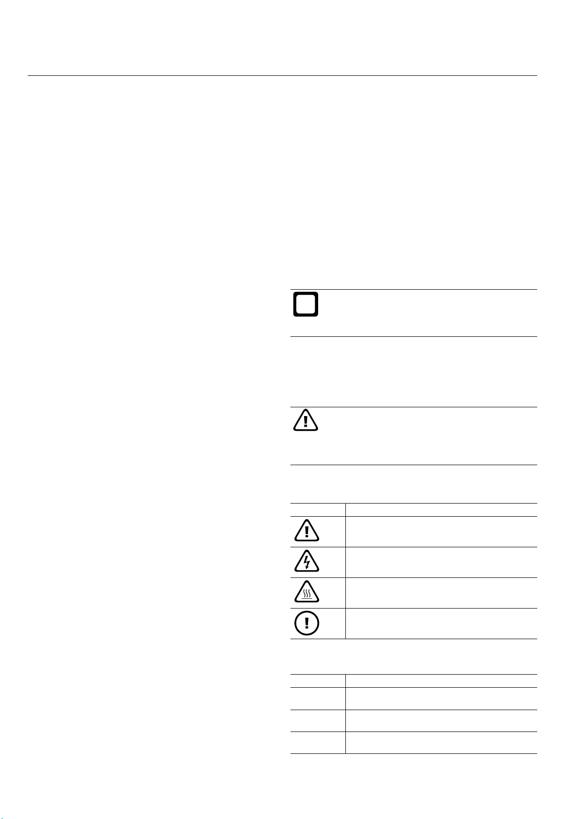
1.1.2 Symbols and possible dangers
Symbol Type of risk
Injury
Electrocution
Burns
(burns, scalding)
Material damage
(appliance, consequential and environmental damage)
1.1.3 Keywords
Keyword Meaning
DANGER Failure to observe this information will result in seri-
WARNING Failure to observe this information may result in se-
CAUTION Failure to observe this information may result in
ous injury or death.
rious injury or death.
non-serious or minor injury.
4 www.ochsner.com | 982000-AIR-M2-M4-EN03.1
OPERATION | Safety
i
i
1.2 Other symbols
► This triangular symbol is used as a bullet point.
These two arrows represent the symbol for an in-
»
struction. This shows that there is something you
must do. The actions required are described step by
step.
{{ These symbols show you the level of a software
menu. In this example, three menu levels are
indicated.
1.3 Units of measurement
Information
In these documents, unless otherwise specied,
all linear measurements (e.g. in tables and illustrations) are given in millimetres.
1.4 Specied performance data
The performance data of the appliance indicated in these
documents (text, tables and diagrams) have been calculated according to standardised measurement conditions.
However, these measurement conditions often do not
completely correspond to the plant-specic conditions applicable in the respective user‘s system. System-specic
factors that can affect the conditions include, for example,
the specic design of the system, the age of the system
and the actual ow rates. For this reason, the stated per-
formance data can differ from plant-specic performance
data.
2. Safety
2.1 Intended use
The appliance is intended for use in a domestic environment. It can safely be used by persons who have received
no instruction. The appliance can similarly be used in a
non-domestic environment such as commercial premises,
as long as it is used in the same instructed manner.
Any use of the appliance that is different from or goes
beyond this is not regarded as intended use. “Intended
use” also includes observing this documentation and the
documentation of any accessories used.
Information
Air pressure and air humidity will affect the operational reliability of the electrical components in the
heat pump system (dielectric strength). The location of the heat pump system must be no more than
1000 m above sea level.
2.2 General safety information
Observe the following safety information and instructions
for the appliance.
► Only qualied contractors should carry out the electri-
cal work and installation of this appliance.
► Commissioning and maintenance of the appliance
may be carried out only by OCHSNER Customer Service or by customer service partners authorised by
OCHSNER.
The stated performance data can be conrmed only if
the measurements taken for the appliance are carried out
according to the relevant standardised measurement conditions.
► The authorised contractor is responsible for compli-
ance with all relevant regulations during installation
and commissioning.
► Operate the appliance only when fully installed and
with all safety equipment tted.
► Protect the appliance from dust and dirt ingress dur-
ing building work. Use the plastic cover provided.
► Alterations to the appliance may be carried out only
by OCHSNER Customer Service or by customer service partners authorised by OCHSNER.
► Functions to protect the heat pump can be enabled
using the controller. However, since the controller is
not certied as a safety device, safety measures in
case of breakdown or damage to the heat pump (e.g.
additional external switching of the safety devices in
use) must comply with local regulations. In the case
of upgrades or updates to the controller software,
all function parameters of the heat pump must be
checked.
► Before commencing work on electrical connections
and installation, the heat pump system must be isolated and voltage-free.
982000-AIR-M2-M4-EN03.1 | www.ochsner.com 5
OPERATION | Appliance description
13_03_001
2
4
1
3
6
5
WARNING: Injury
The appliance may be used by children aged 8 and
up and persons with reduced physical, sensory or
mental capabilities or a lack of experience provided
that they are supervised or that they have been
instructed on how to use the appliance safely and
have understood the possible risks. Children must
not be allowed to play with the appliance. Children
must not be allowed to clean or carry out user
maintenance on the appliance without supervision.
3. Appliance description
The appliance is an air/water heat pump consisting of an
indoor unit and an outdoor unit. The appliance can be used
to heat a building and provide domestic hot water (DHW).
3.1 Functionality
An air/water heat pump extracts thermal energy from the
ambient air (low temperature) and transmits it together with
electrical drive energy in the form of useful heat (higher
temperature) to a heating and/or DHW circuit.
The heat pump consists of separated circuits linked together via heat exchangers:
► Heat source circuit (extracting heat)
► Refrigerant circuit
► Heat sink circuit (supply of heat to the central heating
and/or DHW)
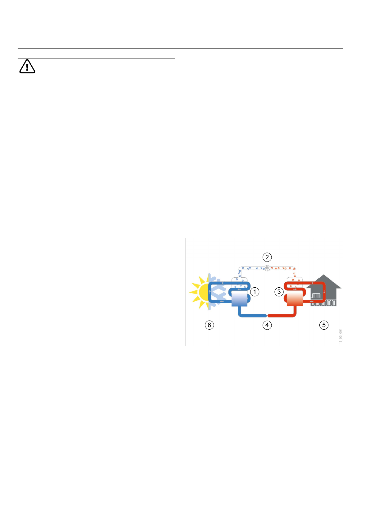
The operating principle of an air/water heat pump:
1 Evaporator (n heat exchanger)
2 Compressor
3 Condenser (plate heat exchanger)
4 Expansion valve
5 Heat sink (heating, DHW)
6 Air as heat source
3.2 Appliance components
3.2.1 Indoor unit
6 www.ochsner.com | 982000-AIR-M2-M4-EN03.1
The indoor unit is intended to be installed only inside the
building. The indoor unit contains the compressor, which
in terms of sound technology is acoustically decoupled a
number of times from the casing. The casing is acoustically
optimised and allows particularly quiet operation.
OPERATION | Appliance description
i
11_02_200_214_01_004
Compressor
The fully hermetically sealed compressor is designed for
high efciency heat pump applications. A suitable starting
current limiter for the compressor is installed in the indoor
unit.
Electric booster heater
The appliance is tted with an electric booster heater
(immersion heater). At low outdoor temperatures, the appliance operates in bivalent-parallel mode. The appliance
can also be combined with an additional heat generator.
Condenser
The condenser takes the form of a plate heat exchanger,
which is built of stainless steel and insulated on all sides
against condensation and heat loss.
3.2.2 Outdoor unit
The outdoor unit is intended to be installed outside. The
outdoor unit is designed as a horizontal split evaporator.
The indoor unit is connected to the outdoor unit with refrigerant lines, along with electrical control and power supply
cables.
► 1x direct circuit (heating and/or cooling)
► 1x mixed circuit (heating and/or cooling)
► 1x directly heated DHW cylinder (with electric booster
heater)
► 1x heat pump (heating and cooling)
► 1x additional heat generator (electric booster heater
or enable contact for external heat generator)
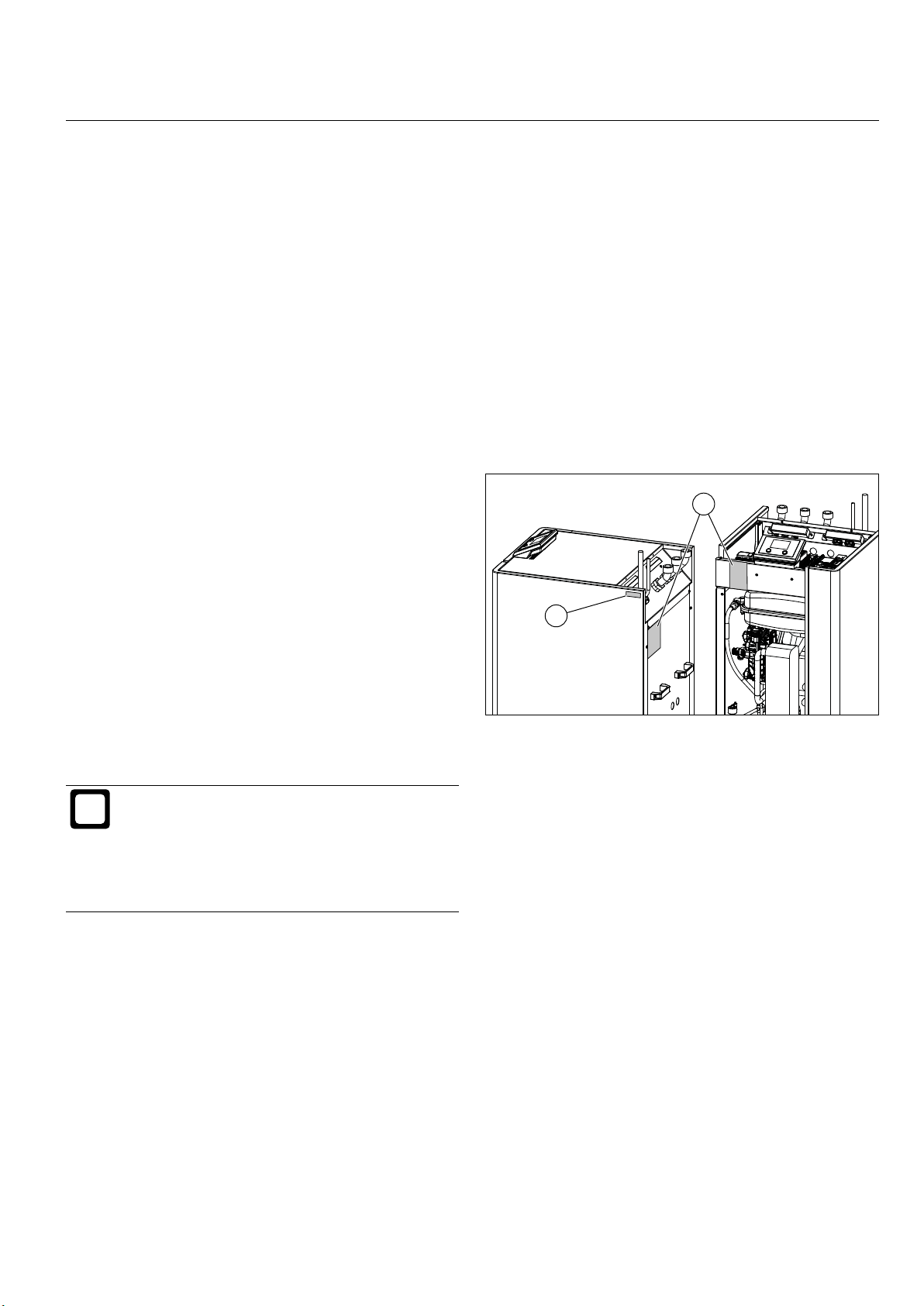
3.3 Name plate
Two name plates are attached to the indoor unit to identify
your heat pump. In addition, a label with the serial number
is attached to the right-hand casing panel of the appliance.
1
2
Evaporator
The evaporator is a part of the outdoor unit and consists
of copper pipes in a set of aluminium ns.
Information
With an air/water heat pump, frost may form on
the evaporator ns of the outdoor unit, depending
on the air temperature (below approx. +7°C), air
humidity and the operating point. The evaporator
ns are automatically de-iced again in the cyclical
defrosting mode of the heat pump.
Fan
The outdoor air is blown across the evaporator by a quiet
fan.
3.2.3 Heat pump control unit
The OCHSNER heat pump controller includes devices
for controlling heat pump heating systems with a cooling
function as well as DHW heating. In its standard version,
the heat pump control unit consists of the OTE controller
and the master controller, both of which are installed in
the indoor unit.
1 Name plate (back of indoor unit and front of control
box)
2 Serial number (right-hand casing panel)
The OTE controller can control the following system circuits
and heat generators:
982000-AIR-M2-M4-EN03.1 | www.ochsner.com 7
OPERATION | Activating settings
i
i
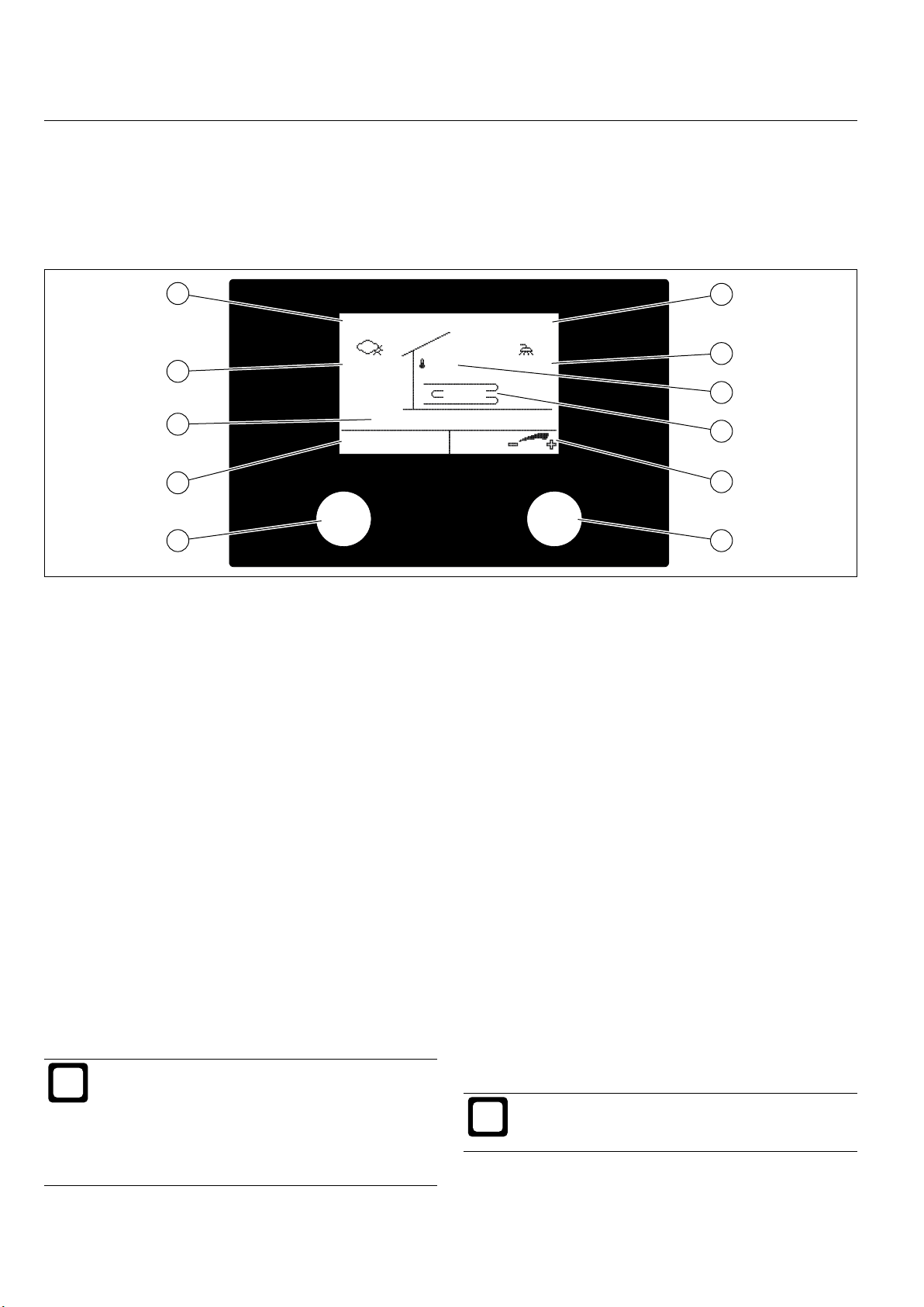
4. Activating settings
Settings are activated with the master controller on the
indoor unit (with graphic display or touchscreen), or via
a remote controller with touchscreen that is attached to
the wall.
5
Mo 09 .01.17 10:02
4
3
2
1 11
1 Button A:
Press to go back one menu step (ESC)
2 Displays function of Button A or fault message
3 Operating status
4 Outdoor temperature
5 Date
6 Time
7 DHW temperature
8 Actual room temperature
9 System temperature
10 Displays function of Button B
11 Button B:
Turn to select from menu or to change setting
Press to conrm (ENTER)
-12.5C 22°C 52.5°C
Heating mode
OCHSNER OTE
The master controller is mounted in an easily accessible
plastic cover on the top of the indoor unit. Two buttons
are provided for controlling the menu, with an illuminated
graphic display.
6
7
32.5°C
MENU
8
9
10
11_01_200_701_01_01_001
Pressing Button B on the right calls up the main menu
with a diagram of the heating system. Each heat consumer (heating circuit, DHW circuit) and each heat generator
(heat pump, electric booster heater, boiler etc.) has its own
menu and corresponding submenus.
Pressing Button A takes you back one step to the previous
menu.
You will nd further information on operating the heat pump
control unit in the control unit‘s operating instructions which
are also supplied with the heat pump.
Information
The heat pump has no separate on/off switch. In
an emergency, the system must be shut down via
the specied safety devices.
Ensure easy access to the safety devices. It
»
must be possible to perform an emergency
shutdown at all times.
8 www.ochsner.com | 982000-AIR-M2-M4-EN03.1
4.1 Operating costs
In the rst two heating seasons, higher running costs are
to be expected (up to 50% more, depending on residual
moisture in the building). Enabling the screed drying program will also increase operating costs further.
4.1.1 Flow temperatures
For optimum operation of your heat pump, you should aim
for the lowest possible heating ow temperatures (and also
DHW temperatures). The maximum system temperature
for your heat pump should be restricted to 60°C.
Information
Increasing the room temperature by 1°C results in
an increase in consumption of 5-7%.
4.1. 2 Ventilation
Any ventilation should be intermittent, especially during
the heating period, and according to your own require-
OPERATION | Maintenance and care
i
i
ments. Intermittent ventilation is considerably more energy
efcient than permanent ventilation, and therefore saves
money. Avoid permanent ventilation.
4.1. 3 Heating setback program
From an energy efciency point of view, using a time pro-
gram to reduce the heating ow temperature is especially
not recommended for air/water heat pumps with low tem-
perature heating systems (such as underoor heating).
These systems are slow to respond and, due to the addi-
tional output from the system required following the end
of the setback phase, it is possible that the second heat
generator (boiler, electric immersion heater) will cut in. This
can lead to higher operating costs.
5. Maintenance and care
We recommend an annual inspection and if necessary
have your heat pump serviced by OCHSNER Customer
Service.
Material damage
Maintenance work on electrical components of the
heat pump may be carried out only by qualied
contractors.
Material damage
Abrasive tools must not be used to clean the evap-
orator ns in the outdoor unit.
Any dirt on the ns should be blown away
»
using compressed air (max. 8 bar), in the di-
rection of normal air ow.
If the ns are very dirty, contact your OCHS-
»
NER system partner or OCHSNER Customer
Service.
If it is necessary to clean the casing sections of the
»
indoor or outdoor unit, use only a damp cloth (with
water or a weak soapy solution). Do not use any abrasive or aggressive cleaning materials.
During the building phase, protect the indoor and
»
outdoor units from dirt and dust with a suitable cover.
Use the plastic cover provided.
Ensure that the heating circuit is lled with sufcient
»
water.
Ensure that any condensation beneath the outdoor
»
unit can drain away without freezing all year round.
Information
If the outdoor unit is covered with a thick layer of
snow, this can reduce system efciency.
Remove snow on and around the outdoor unit
»
as necessary.
If required, install the snow cover available as
»
an accessory for the outdoor unit.
Information
Ensure that the refrigerant circuit of your heat pump
is tested for leaks once a year (in acc. with Regulation (EU) no. 517/2014).
Ensure year-round access to soldered joints in
»
the refrigerant circuit.
Document the results of the leakage test in the
»
system test report.
6. Problem solving
Problem Cause Solution
Too little DHW
is available
or the central heating
system is too
cold.
The appliance
is leaking
water.
If you have a problem that you cannot resolve, contact
the system installer, a qualied contractor or OCHSNER
Customer Service.
Faults are displayed as”Er XXX”on the master controller of
the OTE control unit. If a fault occurs, contact your system
installer. The system installer knows your hydraulic system
and how it operates. The causes of faults can often be
found in the settings or in the hydraulics.
Before contacting the installer, make a note of the serial
number and the heat pump model. The serial number and
heat pump model of your appliance are shown on the name
plate. The name plates are attached to the back of the
appliance on the outside and behind the front appliance
casing panel (control box outer side).
► Customer service hotline for Austria:
Tel: +43 (0) 504245 - 499
Email: kundendienst@ochsner.at
The power
supply to the
appliance has
been cut off
The drain
for the safety valve is
blocked.
Check the safety device on the
main distributor board for your
house. Switch the safety device
back on. If the safety device triggers again after being switched
back on, contact a qualified contractor or OCHSNER Customer
Service.
Clean the safety valve drain. See
„Safety valve drain“ on page 32.
Ensure that the outdoor unit (both the top and the un-
»
derside) is kept free from snow, leaves and twigs and
other foreign bodies.
982000-AIR-M2-M4-EN03.1 | www.ochsner.com 9
► Customer service hotline for Germany:
Tel: +49 (0) 69 256694 - 495
Email: kundendienst@ochsner.de
► Customer service hotline for Switzerland:
Tel: +41 (0) 800 100 - 911
Email: kundendienst@ochsner.com
INSTALLATION | Safety
i
INSTALL ATION
7. Safety
Only a qualied contractor should carry out installation,
commissioning, maintenance and repair of the appliance.
7.1 General safety information
We guarantee trouble-free function and operational reliability only if the original accessories and spare parts intended
for the appliance are used.
7. 2 Regulations, codes and standards
Information
Observe all applicable national and regional regulations and instructions.
8. Appliance description
8.1 Standard delivery
The standard delivery of your appliance includes the following components.
► 1x indoor unit:
The following components are installed in the indoor
unit:
AIR 7
AIR 11
AIR 18
Hydraulic variant M2-1 M2-2 M2-3 M2-4 M4-1 M4-2 M4-3 M4-4
Starting current limiter + + + + + + + +
Flow meter (heat sink
side)
Circulation pump (heat
sink side)
Internal flexible hose + + + + + + + +
Safety valve + + + + + + + +
Master control unit + + + + + + + +
OTE heat pump con-
troller
Diaphragm expansion
vessel 24 l
3-way switching mod-
ule (DHW)
Electric booster heater
8.8 kW
+ + + + + + + +
+ + + + + + + +
+ + + + + + + +
+ + + + - - - -
+ + - - + + - -
+ - + - + - + -
AIR 23
AIR 29
AIR 41
► 1x outdoor unit:
Evaporator, expansion valve, fan
► 3x connection pipes (45°):
For vertical or horizontal connection to the heating
system.
► 1x outdoor temperature sensor (TA)
► 1x contact sensor for a mixed circuit (TMK)
► 2x pocket sensors for a heat pump buffer tank
(TPO, TPM)
► 1x pocket sensor for a DHW cylinder (TB)
► 1xfoundationxingkitfortheoutdoorunit
10 www.ochsner.com | 982000-AIR-M2-M4-EN03.1
INSTALL ATION | Appliance description
11_02_200_202_01_019
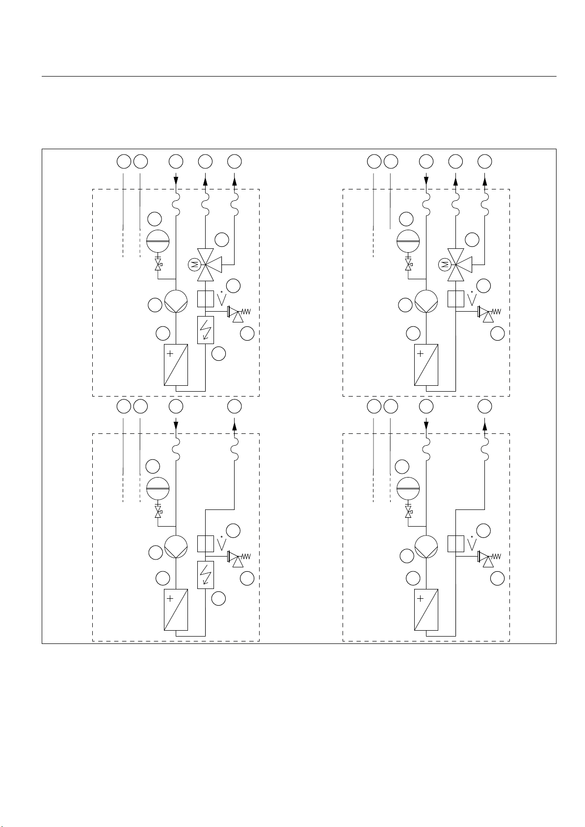
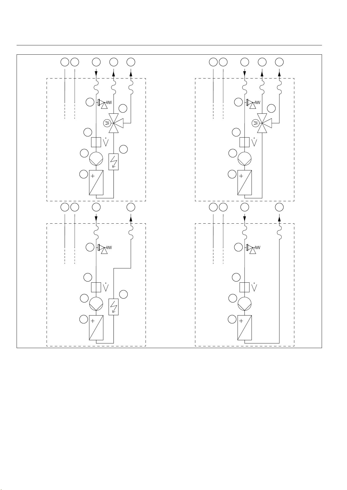
8.2 Hydraulic variants of the indoor unit
The indoor unit is available in eight different hydraulic
variants that are illustrated schematically below. Possible
system congurations for the hydraulic versions of the indoor unit are illustrated in „System schematic diagrams“
on page 68.
M2-3
43 521
43 521
M2-2M2-1
7
8
9
6
12
3 521
10
11
7
8
9
6
12
3 521
10
M2-4
7
6
12
1 Suction gas line
2 Liquid line
3 Heating water/DHW return
4 DHW ow
5 Heating water ow
6 Heat generator pump
7 Diaphragm expansion vessel
8 3-way switching module
9 Flow meter
10 Safety valve
11 Electric booster heater
12 Heat exchanger (heat sink side)
11
7
9
6
10
12
9
10
982000-AIR-M2-M4-EN03.1 | www.ochsner.com 11
INSTALLATION | Appliance description
43 521
43 521
M4-2M4-1
6
7
8
9
10
11
21
3 5
6
7
8
9
11
3 521
M4-4M4-3
6
8
9
11
1 Suction gas line
2 Liquid line
3 Heating water/DHW return
4 DHW ow
5 Heating water ow
6 Safety valve
7 3-way switching module
8 Flow meter
9 Heat generator pump
10 Electric booster heater
11 Heat exchanger (heat sink side)
10
6
8
9
11
11_02_200_202_01_020
12 www.ochsner.com | 982000-AIR-M2-M4-EN03.1
INSTALL ATION | Preparing to install the appliance
i
11_05_200_214_01_001
i
i
9. Preparing to install the appliance
Before installing the indoor and outdoor units, preparatory
work needs to be carried out by qualied contractors.
9.1 Indoor unit installation location
Material damage
The indoor unit is intended to be installed only inside the building. It must not be installed in rooms
with high levels of humidity (permanently above
70%).
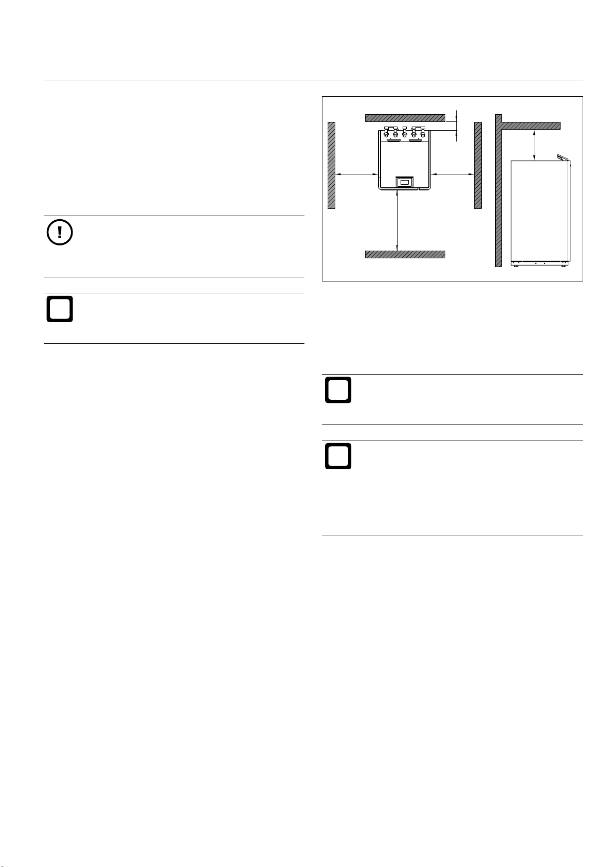
Information
Plan the installation sites for the outdoor and indoor
units such that the pipework carrying the refrigerant is as short, straight and simple as possible.
B
A ≥ 1000 mm
B ≥ 500 mm
C ≥ 500 mm
D ≥ 50 mm
E ≥ 500 mm
D
E
C
A
The installation location for the indoor unit must meet the
following requirements:
► A dry and frost-free room
► Sound optimised environment
► A horizontal, adequate load bearing oor (for weight
of indoor unit, see „Specication“ on page 50)
► Not situated directly below or above bedrooms
► Max. room temperature 30°C
► The installation room must not be subject to a risk of
explosions arising from dust, gases or vapours.
9.1.1 Keep minimum clearances
Observing the specied minimum clearances for the indoor
unit ensures:
► Correct installation of the appliance
► Fault-free operation
► Ability to carry out maintenance on the appliance.
9.2 Outdoor unit installation location
Information
Plan the installation sites for the outdoor and indoor
units such that the pipework carrying the refrigerant is as short, straight and simple as possible.
Information
When laying refrigerant lines in the ground, schedule the work so that the pipe liner can be laid
together with the already inserted refrigerant lines
in the trench between the outdoor and indoor units.
- If the pipe liner is laid empty, inserting the re-
frigerant lines afterwards will be difcult if not
impossible.
The outdoor unit is intended to be installed only out of
doors. Please note the following with regard to the installation location of the outdoor unit:
► Select the outdoor unit installation location such that
the appliance is safely accessible from all sides all
year round.
► Avoid installing it in a hollow or ditch (a “pool” of cold
air).
► An optional snow cover is available to protect the
outdoor unit fan in case of heavy snowfall. Where
necessary, ensure that a snow cover is installed
(according to installation site and local weather
conditions).
982000-AIR-M2-M4-EN03.1 | www.ochsner.com 13
INSTALLATION | Preparing to install the appliance
i
i
Material damage
The air ow through the evaporator must not be
obstructed by surrounding buildings. A reduced air
ow rate can lead to loss of efciency in the system.
Please note the following with regard to installation in
coastal areas:
► The standard design of outdoor unit must be installed
at least 1 km from the sea.
► Outdoor units with special coating, suitable for coast-
al locations, must be installed at least 200 m from the
sea.
► The installation location selected should always be on
the leeward side of the building (the side facing away
from the sea).
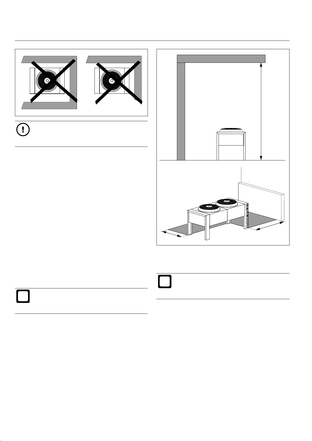
Please note the following with regard to sound emissions
from the outdoor unit:
► Avoid installing on reverberant ooring.
► Avoid installing between building walls. The walls can
increase the noise level.
► Avoid installing next to bedrooms.
Information
Plants and cultivated areas around the outdoor
unit, subject to minimum clearances, can reduce
the noise level of the outdoor unit.
11_05_200_504_002
C
A ≥ 3000 mm (minimum clearance to roof)
B ≥ 1000 mm (minimum clearance to a wall)
C 100 mm or ≥ 1000 mm (minimum longitudinal clear-
ance to a wall)
Information
The minimum clearance between two outdoor
units (e.g. connected in cascade) is 1000 mm on
all sides.
9.3 Foundations for the outdoor unit
A
B
11_05_200_504_001
9.2.1 Keep minimum clearances
Observing the specied minimum clearances for the outdoor unit ensures:
► Correct installation of the appliance
► Fault-free operation
► Ability to carry out maintenance on the appliance.
It is permissible to install the outdoor unit under a roof if the
space around the unit is permanently open on three sides.
14 www.ochsner.com | 982000-AIR-M2-M4-EN03.1
A permanent foundation is required beneath the outdoor
unit. The foundations must meet the structural require-
ments of the outdoor unit (see Specication).
Provide for frost-free drainage (e.g. a gravel bed con-
»
nected to a drain) for condensation that forms on the
outdoor unit.
Where refrigerant lines are to be laid in the ground,
»
ensure correct positioning of the pipe liner when laying the foundations.
Use underground waste pipes (with a smooth inner
»
surface) for the pipe liner.

INSTALL ATION | Preparing to install the appliance
i
11_04_200_504_003
11_04_200_504_004
Ensure that the outdoor unit is adequately secured,
»
paying regard to the wind load occurring at the installation location.
CAUTION: Risk of slipping
If drainage for condensation is inadequate, ice can
build up in winter in the area around the outdoor
unit.
Ensure drainage for condensation is sufcient
»
even at low temperatures.
Information
Insulation used beneath the soil must be made of
a closed-cell material. Otherwise, the thermal insulation of the material will be impaired.
100
900
Dig out the foundation trench.
»
Place in position four underground waste pipes
»
(Ø ≥ 250 mm).
≥ 800
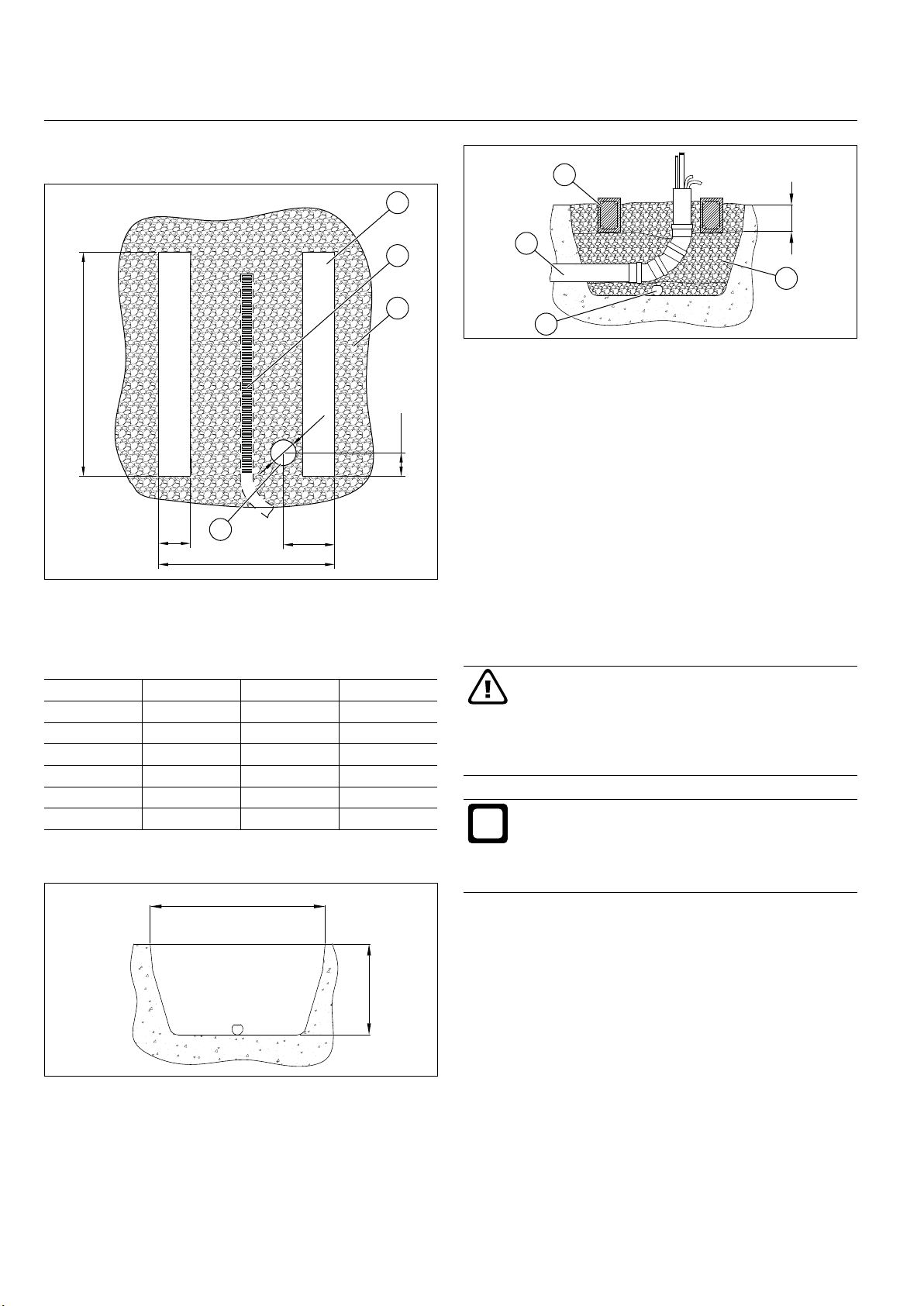
9.3.1 Laying spot foundations
900
4
Ø250
3
2
C
1
1 Pipe liner for the connecting lines (where installed
underground)
2 Gravel bed
3 Drainage pipe (frostproof)
4 Spot foundation (with underground waste pipe)
B
A
Ensure correct horizontal and vertical positioning of
»
the underground waste pipes.
Place a drainage pipe along the base of the trench.
»
≥ 1800
1
2
3
1 Underground waste pipe
2 Pipe liner for underground connecting lines
3 Drainage pipe (frostproof)
4 Gravel bed
In the case of underground connecting lines, allow for
»
the pipe liner.
11_04_200_504_001
Fill the foundation trench with coarse gravel. If the
»
pipe liner (with refrigerant lines) is to be installed at
a later point, in the case of underground connection lines, this must be allowed for in the foundation
trench.
4
Fill the underground waste pipes with concrete.
A B C
AIR 7 1110 270 ≥ Ø160
AIR 11 1110 270 ≥ Ø160
AIR 18 1110 270 ≥ Ø160
AIR 23 2040 300 ≥ Ø200
AIR 29 2040 300 ≥ Ø200
AIR 41 2040 330 ≥ Ø250
Use underground waste pipes when installing spot foundations. When installing spot foundations, we recommend
the following approach:
982000-AIR-M2-M4-EN03.1 | www.ochsner.com 15
»
INSTALLATION | Preparing to install the appliance
i
9.3.2 Laying strip foundations
4
3
2
A
C
150
200
1 Pipe liner for the connecting lines (where installed
underground)
2 Gravel bed
3 Drainage pipe (frostproof)
4 Strip foundations
AIR 7 1400 300 ≥ Ø160
AIR 11 1400 300 ≥ Ø160
AIR 18 1400 300 ≥ Ø160
AIR 23 2250 320 ≥ Ø200
AIR 29 2250 320 ≥ Ø200
AIR 41 2250 350 ≥ Ø250
When laying strip foundations we recommend the following
approach:
1
1100
A B C
≥ 1600
B
1
2
3
1 Reinforced strip foundation
2 Pipe liner for underground connecting lines
3 Drainage pipe (frostproof)
4 Gravel bed
In the case of underground connecting lines, allow for
»
the pipe liner.
Fill the foundation trench with coarse gravel. If the
»
pipe liner (with refrigerant lines) is to be installed at
a later point, in the case of underground connection lines, this must be allowed for in the foundation
11_04_200_504_002
trench.
Construct the two reinforced strip foundations.
»
9.3.3 Installing on at roofs
WARNING: Risk of falling
Working on a at roof without fall protection constitutes a risk.
When working on a at roof, observe the laws
»
relating to occupational safety in your region.
Always be aware of the open edge.
»
Information
Avoid installing the outdoor unit on the roof above
residential buildings or on car ports attached to residential buildings, due to the risk of structure-borne
noise transmission.
Loads and stresses on roof structure
≥ 300
4
11_04_200_504_006
Note that when outside temperatures are very low,
»
ice can form beneath the outdoor unit.
≥ 800
11_04_200_504_005
Dig out the foundation trench.
»
Place a drainage pipe along the base of the trench.
»
16 www.ochsner.com | 982000-AIR-M2-M4-EN03.1
In terms of roof structure loads, allow for an ice load
»
of 400 kg/m² in addition to the dead weight of the
outdoor unit.
INSTALL ATION | Preparing to install the appliance
i
3
2
1
1 Flat roof
2 Refrigerant lines in open air (enclosed in thermal in-
sulation with UV protection)
3 2x concrete slabs attached with exible adhesive (per
leg of the outdoor unit). The outdoor unit is afxed to
the concrete slabs
4 Anti-vibration mounts
When installing the outdoor unit on a freestanding car port,
a garage roof or a storage space roof, please note the
following:
Ensure that the outdoor unit is adequately secured,
»
paying regard to the wind load occurring at the installation location.
Take account of the concentrated load arising from
»
the dead weight of the outdoor unit (including the
roof xings) and the surface load caused by possible
build-up of ice.
Ensure suitable structure-borne sound separation be-
»
tween the outdoor unit and the installation points on
the roof.
4
9.4 Preparing the refrigerant lines
Information
If the appliance, the refrigerant lines, the pipe xings and the wall outlets are not installed correctly,
structure-borne sounds can be transmitted to the
building.
Ensure that the refrigerant lines are in-
»
11_06_200_202_006
stalled in a way that ensures insulation from
structure-borne noise. The system installer
carrying out the work is responsible for this.
Material damage
Use only copper pipes suitable for refrigerant
(D IN 12735-1). Thin-walled pipes run the risk of
bursting.
Please observe the stipulated diameters and
»
wall thicknesses of the copper pipes.
Material damage
Incorrect or premature opening of the pipe connections and cutting of the refrigerant lines can allow
dirt and moisture to enter the refrigerant circuit.
Do not open the connections on the indoor
»
or outdoor units until just before installing the
refrigerant lines.
Cut the refrigerant lines with a suitable pipe
»
cutte r.
Prevent swarf from contaminating the pipe
»
connections and refrigerant lines.
Once cut, ll the refrigerant lines with a sub-
»
stance such as nitrogen.
Keep the refrigerant lines closed until just be-
»
fore installation.
Pipe connections for the refrigerant lines (suction gas and
liquid lines) are supplied soldered closed, both for the indoor unit and the outdoor unit. Appropriate copper pipes
for refrigerant lines are supplied sealed at both ends and
lled with nitrogen.
Please note the following with regard to routing of the refrigerant lines:
Keep to a minimum the distance between the indoor
»
and outdoor units, in order to minimise heat loss from
the refrigerant lines.
Select the installation sites for the indoor and outdoor
»
units such that the maximum permissible line lengths
and height differentials are not exceeded.
Avoid routing the lines in the vicinity of bedrooms.
»
The refrigerant in the lines can generate noise under
certain operational conditions.
982000-AIR-M2-M4-EN03.1 | www.ochsner.com 17
INSTALLATION | Preparing to install the appliance
i
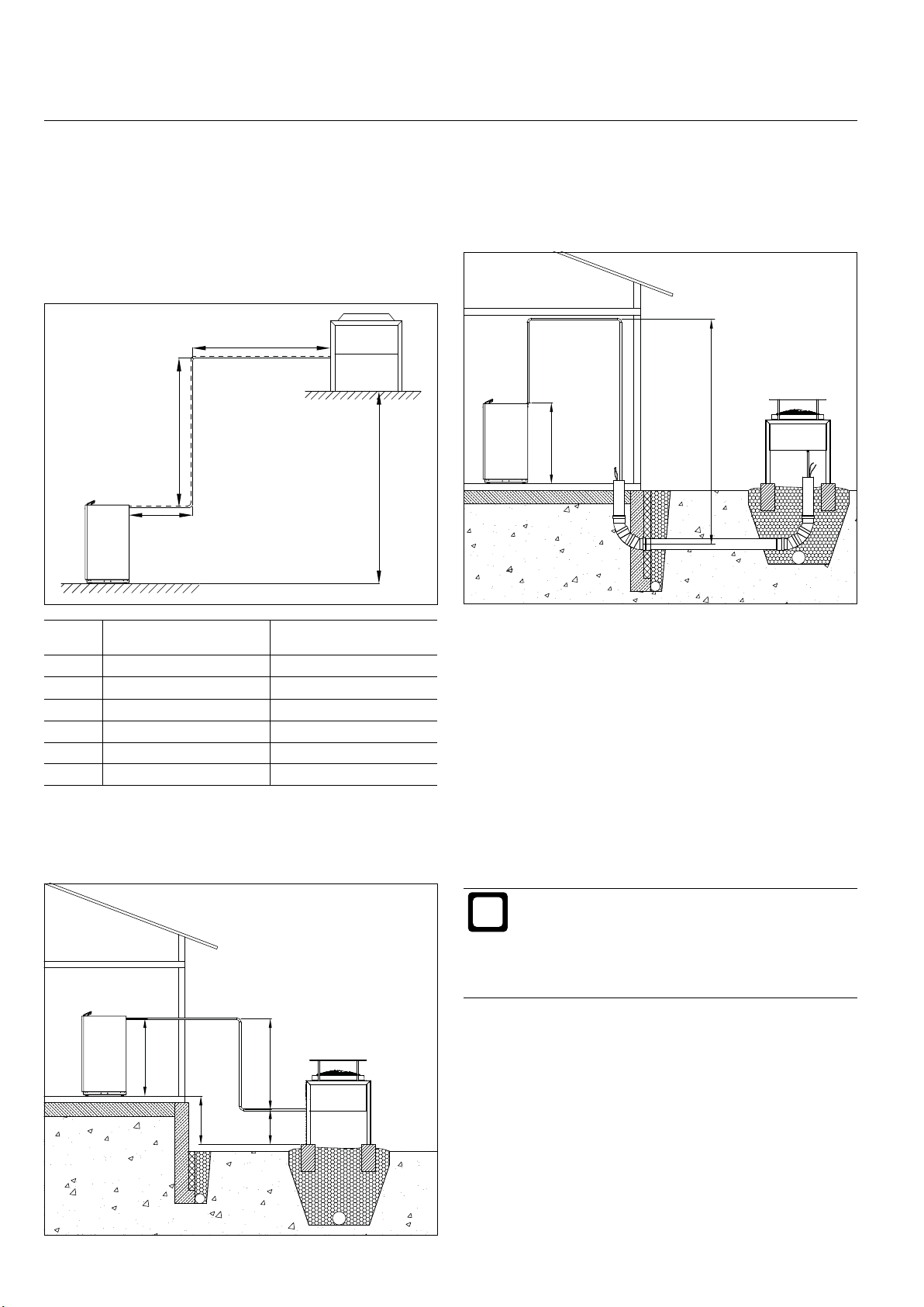
9.4.1 Line lengths
Observe the maximum permissible line lengths for
»
the refrigerant lines.
Where the outdoor unit is positioned higher than the
»
indoor unit, observe the maximum permissible height
differential between the two units.
C
B
A
Where a line routed along the ceiling is used in
»
conjunction with an underground connection line,
observe the maximum permissible height differential
between the highest and lowest points of the refrigerant lines.
1223
D
11_06_200_202_001
≤ 3500
11_06_200_202_002
A + B + C
(sum of line lengths)
AIR 7 ≤ 20 m ≤ 10 m
AIR 11 ≤ 20 m ≤ 10 m
AIR 18 ≤ 20 m ≤ 10 m
AIR 23 ≤ 20 m ≤ 10 m
AIR 29 ≤ 20 m ≤ 10 m
AIR 41 ≤ 16 m ≤ 5 m
Where the outdoor unit is positioned lower than the
»
indoor unit, observe the maximum permissible height
differential between the highest and lowest points of
the refrigerant lines.
1180
(max. height differential)
≤ 3500
D
9.4.2 Pipe diameter
The pipe diameter data for refrigerant lines shown below
applies as long as the following are observed:
► A maximum of eight 90° pipe bends
► With pipe diameters of < 35 mm, use a suitable pipe
bending tool to create the pipe bends
► With pipe diameters of ≥ 35 mm, use type 5002 pipe
bends
► Bending radii of ≥ 1 m are treated as straight runs
Information
Refrigerant lines with a pipe diameter of ≥ 35 mm
are created from rigid copper pipes in 5 m lengths.
With underground refrigerant lines, provide an
»
assembly shaft at connection sites to facilitate
soldering and maintenance work.
≤ 2970
18 www.ochsner.com | 982000-AIR-M2-M4-EN03.1
650
11_06_200_202_003
INSTALL ATION | Preparing to install the appliance
Pipe diameter of the refrigerant line
Refrigerant line up to 6 m Refrigerant line up to 8 m
Liquid line Suction gas
line
AIR 7 10 18 10 18
AIR 11 12 18 12 18
AIR 18 12 22 12 22
AIR 23 12 22 16 2x22
AIR 29 16 2x22 16 2x22
AIR 41 16 42 16 42
AIR 41 16 4x22 16 4x22
Pipe diameter of the refrigerant line
Refrigerant line up to
10 m
Liquid line Suction gas
line
AIR 7 10 18 10 18
AIR 11 12 22 12 22
AIR 18 12 22 12 2 x18
AIR 23 16 2x22 16 2x22
AIR 29 16 2x22 16 2x22
AIR 41 16 42 16 42
AIR 41 16 4x22 16 4x22
Pipe diameter of the refrigerant line
Refrigerant line up to
14 m
Liquid line Suction gas
line
AIR 7 10 18 10 18
AIR 11 12 22 12 22
AIR 18 12 2 x18 12 2x22
AIR 23 16 2x22 16 2x22
AIR 29 16 2x22 16 35
AIR 29 16 2x22 16 3x22
AIR 41 16 42 16 42
AIR 41 16 4x22 16 4x22
Liquid line Suction gas
line
Refrigerant line up to
12 m
Liquid line Suction gas
line
Refrigerant line up to
16 m
Liquid line Suction gas
line
9.4.3 Preparing the wall outlets
Whether the refrigerant lines between the indoor and
outdoor units are to be routed above or below ground, ap-
propriate and plant-specic wall outlets need to be created
through the outer wall of the building.
Ensure that the wall outlets are constructed in an ap-
»
propriate, plant-specic manner.
Take the construction of the wall (tiles, concrete) into
»
account.
Take the prevailing groundwater situation into
»
account.
Material damage
Incorrectly created wall outlets can cause signicant damage to property, due to water (seepage,
condensation, floodwater) penetrating into the
building or stonework. Where the wall outlets are
created below ground level, the breach must be
appropriate to local conditions at the site (e.g.
non-accumulating or accumulating seepage water,
groundwater under pressure).
Use a suitable pipe liner or wall sleeve for the
»
wall outlet.
Tie the external end of the wall outlet in to the
»
external waterproof seal of the building.
Ensure that the pipe liner is arranged with a
»
slight fall (at least 2%) to the outside.
On both the outside and inside edge of the
»
wall, use appropriate ring seals to seal the
space between the wall sleeve and the refrigerant lines and electrical cables passing
through.
Material damage
PU foam is not suitable as a sealant for the pipe
li ner.
Pipe diameter of the refrigerant line
Refrigerant line up to
18 m
Liquid line Suction gas
line
AIR 7 10 18 10 18
AIR 11 12 22 12 22
AIR 18 12 2x22 12 2x22
AIR 23 16 2x22 16 2x22
AIR 29 16 35 16 35
AIR 29 16 3x22 16 3x22
982000-AIR-M2-M4-EN03.1 | www.ochsner.com 19
Refrigerant line up to
20 m
Liquid line Suction gas
line
INSTALLATION | Preparing to install the appliance
i
i
i
i
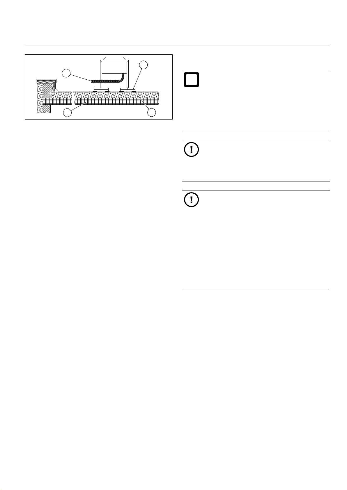
9.4.4 Preparing refrigerant lines passing through open
air
3
2
1
6
1 Appropriately sealed wall outlet (particularly where
there is a risk of ooding)
2 Appropriate sealing of the refrigerant lines as they
pass through the wall outlet
3 Refrigerant lines in open air (enclosed in thermal in-
sulation with UV protection)
4 Reinforced strip foundation
5 Drainage pipe (frostproof)
6 Foundation
Information
All solder sites on the copper pipework of the refrigerant line must be accessible all year round for
maintenance purposes (in accordance with Regulation (EU) no. 517/2014).
Run the refrigerant lines between the indoor and out-
»
door units.
4
5
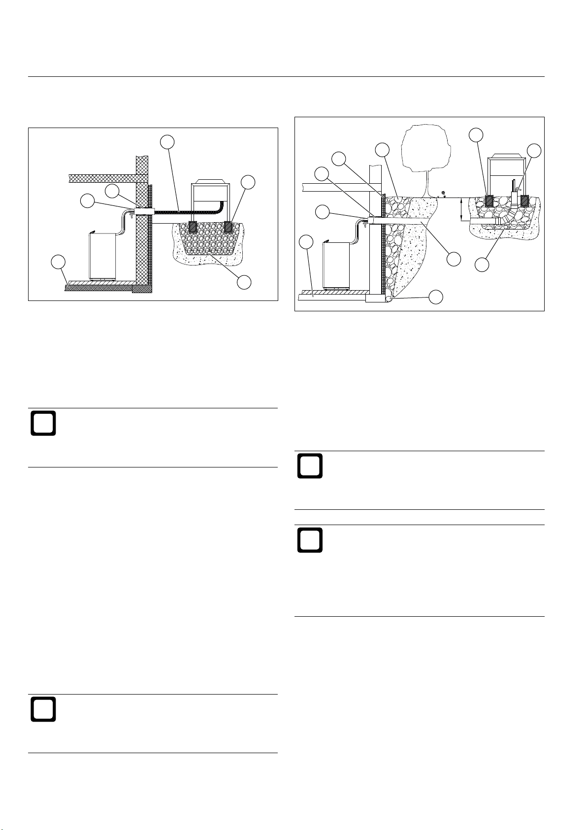
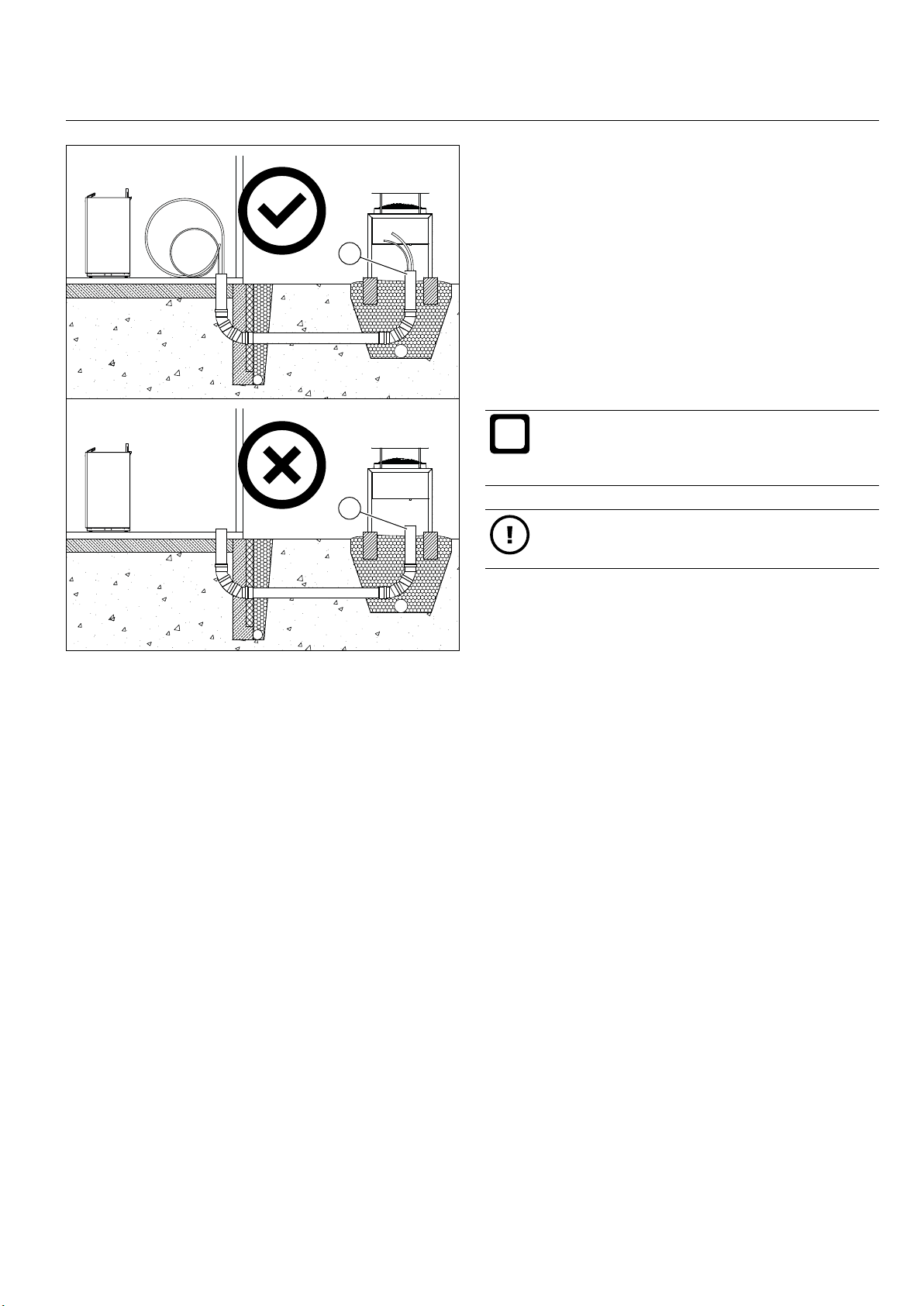
9.4.5 Preparing underground refrigerant lines
5
3
2
1
10
11_06_200_202_005
1 Appropriately sealed wall outlet
2 Appropriate sealing of the refrigerant lines as they
pass through the pipe liner
3 Insulation
4 Gravel
5 Reinforced strip foundation
6 Appropriate sealing at the end of the pipe liner (be-
tween refrigerant lines and pipe liner)
7 Drainage pipe (frostproof)
8 Pipe liner (with min. 2% fall to outside)
9 Drain
10 Foundation
Information
All solder sites on the copper pipework of the refrigerant line must be accessible all year round for
maintenance purposes (in accordance with Regulation (EU) no. 517/2014).
4
~ 600
8
7
9
6
11_06_200_202_004
Allow some surplus length in the refrigerant lines
»
between the connections at the indoor and outdoor
units.
Ensure that the wall outlets are sealed in an appropri-
»
ate, plant-specic manner.
Use suitable sound-insulating pipe xings to secure
»
the refrigerant lines.
Insulate the refrigerant lines with suitable insulating
»
material where they pass through open air between
the indoor and outdoor units, to prevent formation
of condensation. When passing through open air
outside, the insulating material must also have UV
protection.
Information
Where the refrigerant lines run horizontally through
open air, use suitable supports. Take steps to prevent open refrigerant lines from being walked or
driven on.
Information
When laying refrigerant lines in the ground, schedule the work so that the pipe liner can be laid
together with the already inserted refrigerant lines
in the trench between the outdoor and indoor units.
- If the pipe liner is laid empty, inserting the re-
frigerant lines afterwards will be difcult if not
impossible.
20 www.ochsner.com | 982000-AIR-M2-M4-EN03.1
INSTALL ATION | Preparing to install the appliance
i
1
Ensure that the wall outlets are appropriate and
»
plant-specic, and that the pipe liner is appropriately
sealed.
Ensure that the open end of the pipe liner at the
»
outdoor unit is properly sealed. For sealing the refrigerant lines in the pipe liner, use for example an
appropriate ring seal or a UV-resistant, permanently
exible sealing compound.
Any exposed refrigerant lines outside the pipe liner
»
must also be protected from a build-up of condensation with appropriate insulating material. Out of doors,
the insulating material must also have UV protection.
Information
Insulation used beneath the soil must be made of
a closed-cell material. Otherwise, the thermal insulation of the material will be impaired.
2
1 Where the pipe liner has two 90° bends, it must be
laid together with the refrigerant lines.
2 If the pipe liner is laid empty, it will not be possible to
insert the refrigerant lines afterwards.
For the underground pipe liner, use rigid waste pipes.
»
Use a pipe liner of a suitable diameter for the sys-
»
tem-specic refrigerant lines and the planned pipe
bends (see „Foundations for the outdoor unit“ on
page 14).
For 90° bends in the pipes, use either 3x 30° bends
»
or 6x 15° bends (depending on the diameter of the
pipe liner and the depth at which it is laid).
At the point where the refrigerant lines are connected
»
to the outdoor unit, create a suitable trench.
11_06_200_202_007
Material damage
PU foam is not suitable as a sealant for the pipe
li ner.
Dig a straight trench between the wall outlet and the
»
trench at the outdoor unit.
Lay the pipe liner, with the refrigerant lines already
»
inserted, into the trench between the outdoor and indoor units.
Lay the electrical control leads and power supply
»
cables in a suitable electrical conduit. The optional
OCHSNER cable harness is suitable for laying direct
into the ground.
Allow some surplus length in the refrigerant lines
»
between the connections at the indoor and outdoor
units.
982000-AIR-M2-M4-EN03.1 | www.ochsner.com 21
INSTALLATION | Preparing to install the appliance
i
i
i
9.5 Preparing the electrical connections
WARNING: Electrocution
All electrical connection and installation work must
be carried out according to the applicable national
and regional regulations.
WARNING: Electrocution
Before commencing work on electrical connections
and installation, the heat pump system must be
isolated and voltage-free.
WARNING: Electrocution
Work on electrical connections and installation may
be conducted only by qualied contractors.
Material damage
This appliance contains frequency converters (e.g.
EC circulation pumps, EC fan motors). Leakage
currents may arise in normal operation. In the event
of faults, these components may cause DC fault
currents. An incorrectly selected RCD may trip during normal operation or, in the event of a fault, may
not trip at all or only trip after a delay.
Make sure that the power supply for this
»
appliance is separate from the domestic installation.
If local conditions require the installation of an
»
RCD, use type B AC/DC-sensitive RCDs.
► For the integral electric booster heater (8.8 kW), a
suitable high limit safety cut-out (HLSC) is installed in
the indoor unit.
Information
The main power circuit for the compressor has
no upstream power contactor on the machine
side. Control devices and equipment to disconnect and shut down all supply voltages across
all poles, which must be provided on the system
side, must meet the technical safety requirements
of EN 60204-1 sections 5 and 13.4.5, as well as the
international regulations in the IEC 60947 series.
Material damage
Protect the main power circuit (compressor), the
control circuit (control unit) and the electric booster
heater separately from one another.
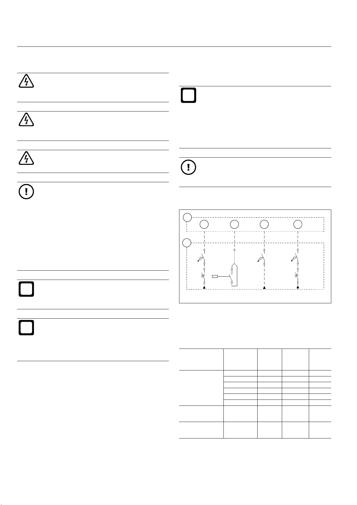
9.5.1 Heat pumps for three-phase alternating current
1
3 4 5 6
2
C13A B16A
Information
It is essential that the regulations of the responsible
power supply utility (PSU) and the applicable EN
standards be observed.
Information
The values specied in this documentation for
circuit protectors and cable cross-sections are
standard values. The contractor carrying out the
work is responsible for plant-specic sizing of safety equipment and cable cross-sections.
► For the electrical connection, use the system principle
schematic appropriate to your heat pump system from
section „System schematic diagrams“ on page 68.
► The outdoor unit takes its power supply from the in-
door unit. The supply cable for the fan in the outdoor
unit is protected by an internal C10A circuit breaker in
the indoor unit.
► In the case of a fault, the protection on the main pow-
er circuit (compressor) and electric booster heater
must break the circuit across all poles.
3 x 400 VAC 1 x 230 VAC 3 x 400 VAC
1 Heat pump indoor unit control box
2 Main system distributor board
3 Supply to main power circuit (compressor)
4 PSU signal contact
5 Supply to control circuit (OTE controller)
6 Supply to electric booster heater
Description Typ e Max.
Main power circuit
(compressor and
fan)
Electric booster
heater
Control circuit
(control unit)
AIR 7 C11A 13.5 5.4 C10A
AIR 11 C 11A 20.0 7.9 C10A
AIR 18 C11A 32.0 11. 4 C16A
AIR 23 C12A 50.5 16.8 C20A
AIR 29 C12A 49.5 21.1 C25A
AIR 41 C12A 63.5 24.8 C25A
AIR 7 C11A
–
AIR 41 C12A
AIR 7 C11A
–
AIR 41 C12A
starting
current
[A]
Max. operating
current
[A]
– 14 B16A
– 6 C13A
11_02_200_202_01_010
Fuse
► All power supply cables must be protected against
surges and short circuits.
22 www.ochsner.com | 982000-AIR-M2-M4-EN03.1
INSTALL ATION | Preparing to install the appliance
i
i
Material damage
Operating a three-phase motor (compressor,
pumps, fans) for long periods using an incorrectly
phased three-phase supply will damage the motor.
Ensure that all three-phase motors are
»
connected to a three-phase supply with a
clockwise rotating eld.
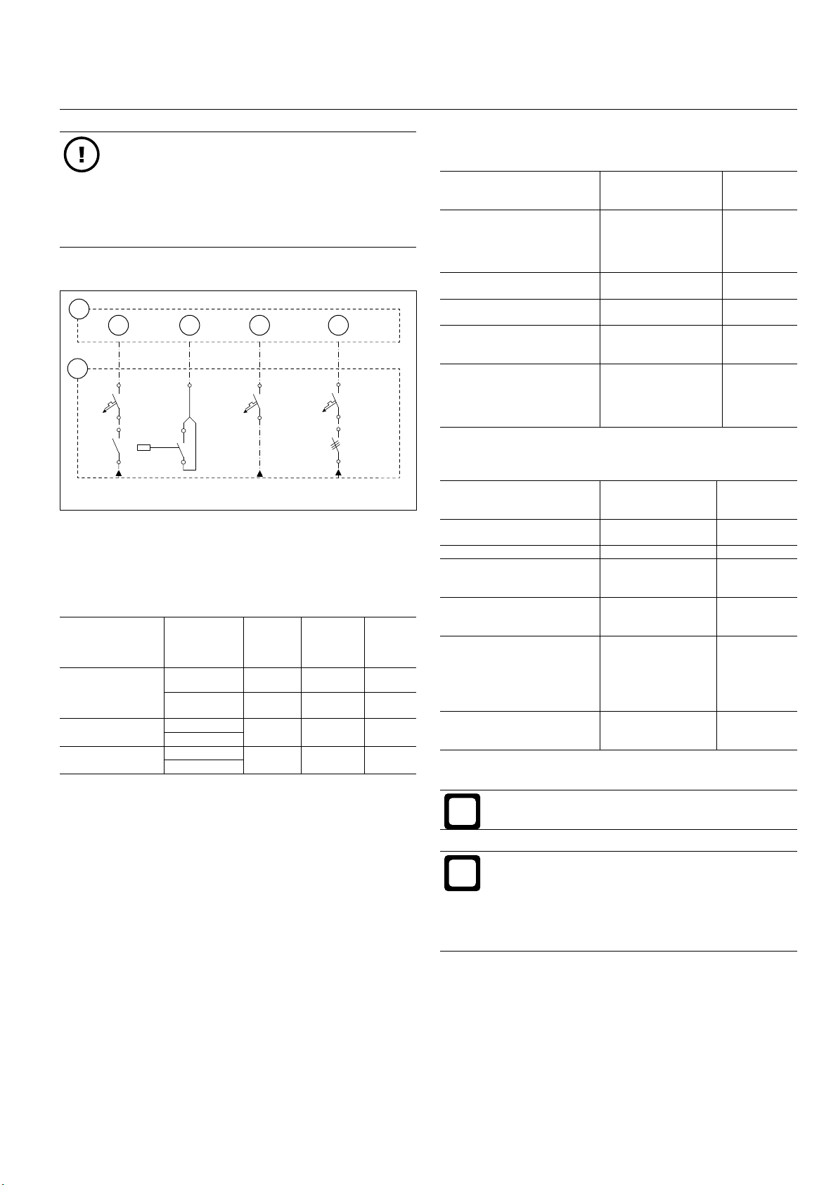
9.5.2 Heat pumps for single phase alternating current
1
3 4 5 6
2
C13A B16A
1 x 230 VAC 1 x 230 VAC 3 x 230 VAC
1 Heat pump indoor unit control box
2 Main system distributor board
3 Supply to main power circuit (compressor)
4 PSU signal contact
5 Supply to control circuit (OTE controller)
6 Supply to electric booster heater
Description Typ e Max.
Main power circuit
(compressor and
fan)
Electric booster
heater
Control circuit
(control unit)
AIR 11 C 11B 48.5 20.8 C25A
AIR 18 C11B 80.0 30.0 C40A
AIR 11 C 11B – 12.8 B16A
AIR 18 C11B
AIR 11 C 11B – 6 C13A
AIR 18 C11B
starting
current
[A]
Max. operating
current
[A]
Fuse
9.5.3 Cables from main distributor to indoor unit
Description Wires Min. cable
Supply to electric booster
heater
(8.8 kW electric immersion
heater)
Control circuit supply 1x 2 30 VAC
Supply to pumps and servomotors
Sensor leads
(system temperature sensors)
Bus leads
(eBus connections from
OTE controller to remote
controllers or auxiliary
modules and in cascades)
3x 400 VAC
(L1/L2/L3/N/PE)
or
3x 230 VAC
(L/L/L/N/PE)
(L/N/PE)
1x 23 0 VAC
(L/N/PE)
2x
(shielding recommended)
Example:
Y(ST)Y 2x2x0.8
(shielded cable design
and twisted cable
pairs)
9.5.4 Cables from indoor to outdoor unit
Description Wires Min. cable
11_02_200_202_01_024
Fan power supply 1x 23 0 VAC
Fan alarm (TK) 2x 230 VAC 1.5 mm²
Fan speed
(0-10 VDC)
Defrost sensor (TQE, TQA) 4x
Pulse lead
(for stepper motor on electronic expansion valve)
Suction gas sensor S2
(for expansion valve controller)
(L/N/PE)
2x
(shielding recommended)
(shielding recommended)
4x
(shielding recommended)
Example:
ÖLFLEX® CLASSIC
100 CY
2x
(shielding recommended)
9.5.5 Temperature sensor
cross-section
2.5 mm²
1.5 mm²
1.0 mm²
1.0 mm²
0.8 mm²
cross-section
1.5 mm²
1 mm²
1 mm²
0.8 mm²
1 mm²
Information
The maximum line length for sensor leads is 50 m.
Information
Sensor leads must be routed separately from 230 V
and 400 V cables. If a minimum distance of 20 cm
cannot be maintained, then shielded cables should
be used. The shielding should be connected to the
earth rail of the heat pump.
Defrost sensors (TQA, TQE):
The two defrost sensors are factory-installed in the evaporator on the outdoor unit.
982000-AIR-M2-M4-EN03.1 | www.ochsner.com 23
INSTALLATION | Preparing to install the appliance
i
i
Outdoor temperature sensor (TA):
nected directly to the OTE controller (1x 230 VAC power
supply).
Fit the outdoor temperature sensor at a height of ap-
»
prox. 2.5 m to the outside wall of the building (on the
north-west side). Make sure that the outdoor temperature sensor is not exposed to direct sunlight or wind,
as this will impair the control characteristics.
Information
Avoid tting the outside temperature sensor to the
casing of the outdoor unit or in the air ow from
the outdoor unit.
Buffer sensor (TPO, TPM):
In heat pump buffer tank, two buffer sensors are required.
The heat pump is switched on on the basis of readings
from the TPO and switched off on the basis of those from
the TPM.
Install a sensor pocket in the female socket provided
»
for the upper buffer sensor (TPO)
Install a sensor pocket in the female socket provided
»
for the lower buffer sensor (TPM)
DHW sensor (TB):
Material damage
A test run of the pumps and servomotors may be
conducted only on a system that has been prepared for commissioning. The hydraulics must be
fully connected.
9.5.7 PSU signal contact
Tariff switching on the heat pump system
In the case of tariff switching (with interrupted power delivery), the heat pump is temporarily shut down by the power
supply utility (PSU).
Uninterrupted tariff
In the case of tariff switching with uninterrupted power
delivery, the heat pump is temporarily shut down by the
power supply utility. A PSU signal contact is provided for
this purpose on the indoor unit. To activate the function,
remove a cable bridge in the control box and connect the
PSU signal contact cable (see „Electrical connection of the
indoor unit“ on page 34).
OCHSNER DHW cylinders are tted with appropriate female sockets for installing the sensor.
Install the DHW sensor in the top one-third of the
»
DHW cylinder (or at the very least in the top half). The
lower the selected position of the DHW sensor, the
larger the switching hysteresis (5-15 K) will need to
be.
Information
Ensure that the DHW sensor is correctly positioned
and extends beyond the cylinder insulation into the
interior of the DHW cylinder. This is the only way in
which the temperature can be captured correctly.
Mixer sensor (TMK):
If, in addition to a direct heating circuit, your system also
has a heating circuit with mixing valve, then a mixer sensor
must be installed. The mixer sensor is supplied with the
heat pump, as a contact sensor including band clamp and
heat conducting paste.
Install the mixer sensor immediately downstream
»
of heating circuit circulation pump 2 for the heating
circuit with mixing valve, on a (metal) pipe made of a
good heat-conducting material.
Shutdown by means of a tariff contactor
In the case of shutdown by means of a tariff contactor installed on behalf of the customer (sealed by the PSU), the
power supply to the heat pump compressor is disconnected. Here, it is essential to connect an auxiliary contact to
the tariff contactor (N/C contact) of the PSU signal contact
on the indoor unit.
Night tariff
Where tariff switching takes place within the meter (night
tariff), the PSU signal contact is not connected.
9.5.8 Smart Grid
For the Smart Grid function, special descriptions are available on request from your OCHSNER Customer Service
department.
9.5.6 Pumps and servomotors (230 VAC)
Pumps (heating circuit pumps, DHW charging pump) and
servomotors (switching module, mixing valve) are con-
24 www.ochsner.com | 982000-AIR-M2-M4-EN03.1
INSTALL ATION | Appliance installation
i
i
11_02_200_214_01_005
11_02_200_214_01_001
10. Appliance installation
10.1 Installation of indoor unit
10 .1.1 Delivery and transportation
The appliance is delivered on a one-way pallet, wrapped
in lm. The appliance casing is assembled on delivery.
Information
Should you notice any transportation damage to
the appliance, you must report such damaged immediately when the delivery is unloaded. Claims
for transportation damage cannot be made subsequently.
Material damage
Protect the appliance from damage by using
»
transport belts.
When transporting, protect the appliance from
»
impact.
► The appliance is secured to the one-way (recyclable)
pallet of the transport packaging with screws.
► The transport packaging or one-way pallet is suitable
for transportation using a forklift truck.
► For level transportation to the installation location, the
appliance may remain in the transport packaging.
► Leave the appliance in the transport packaging or on
the one-way pallet for lifting and moving by crane or
forklift.
► The standard packaging of the appliance does not
provide protection against the weather or sea water.
► The appliance may be stored and transported only at
temperatures of between -20°C and +45°C.
► The appliance must be stored in its transport
packaging.
Information
If the route to the installation location is difcult,
the transport packaging should be removed and
the appliance casing disassembled.
Please note the following when removing the transport
packaging:
Remove the transport packaging.
»
Undo and remove the eight woodscrews on the two
»
transport xing brackets (left and right) securing the
appliance to the one-way pallet.
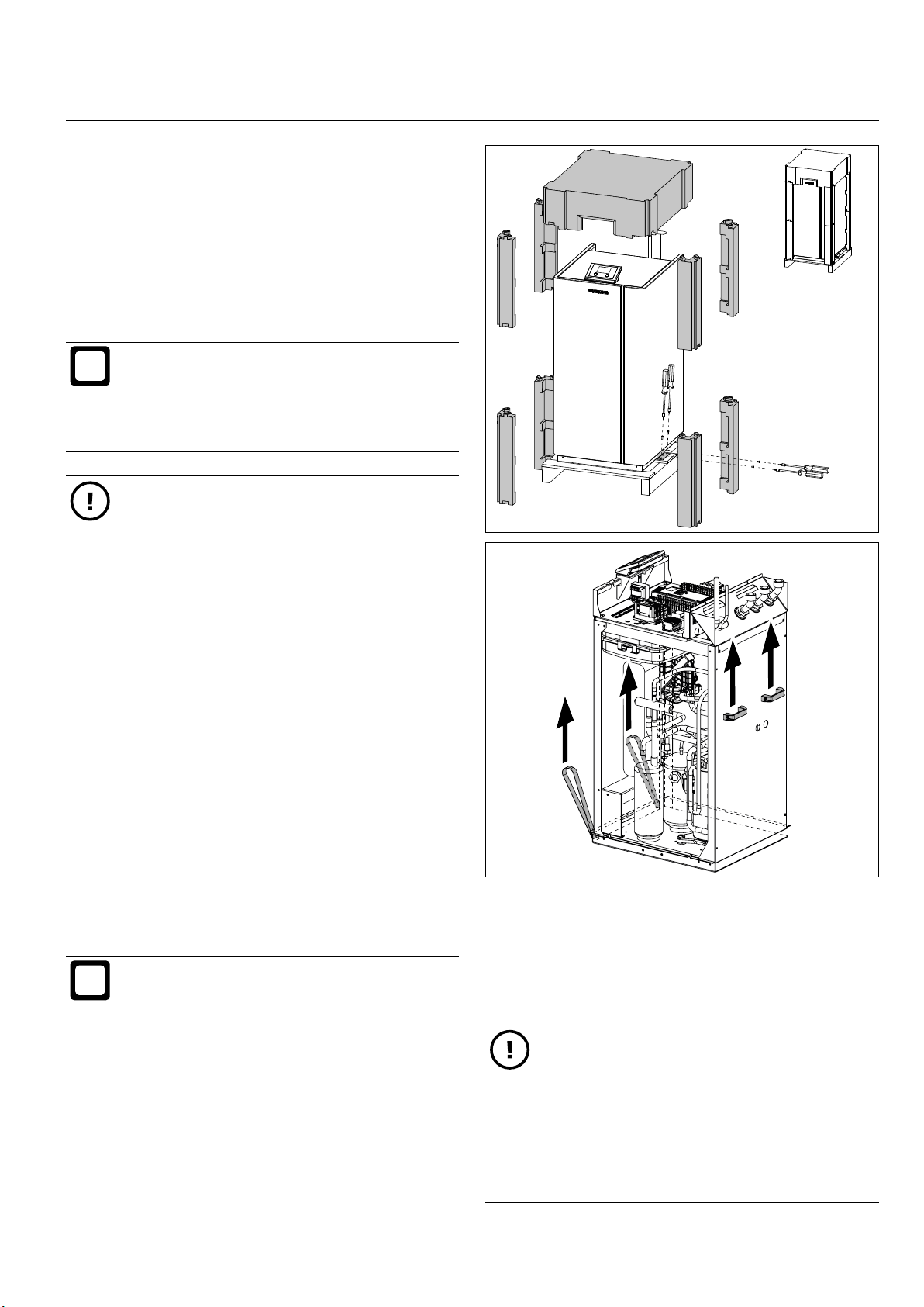
Use the pre-installed transport aids (2 lifting slings at
»
the front and 2 lifting handles at the rear) to lift and
transport the appliance.
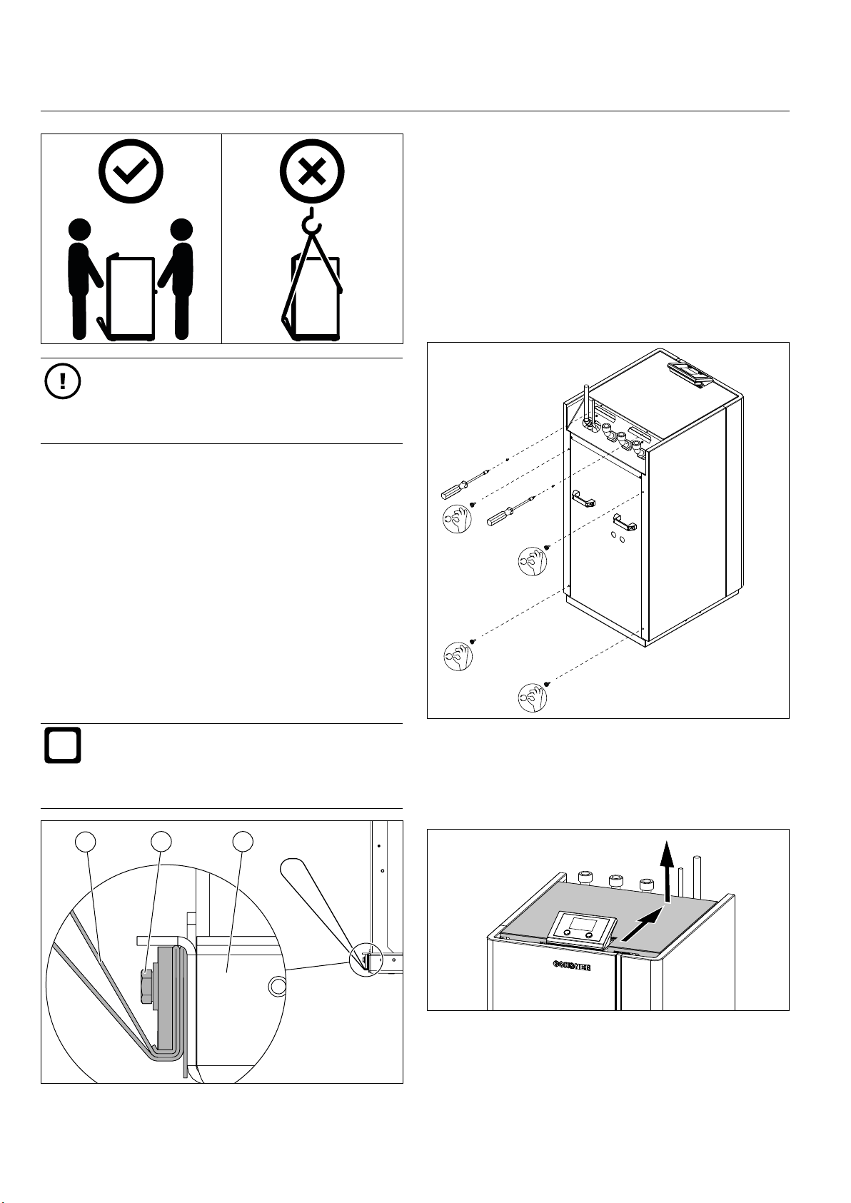
Transport the appliance in an upright position. Over
»
short distances, you may transport the appliance
carefully at an angle of up to 30°.
Material damage
Note the following points when carrying the appliance with the pre-installed transport aids:
- When lifting and carrying the appliance, make
sure that all 4 transport aids are pulled evenly
and at the same time.
- Ensure that the appliance casing is not damaged during transport.
- The transport aids are not suitable for lifting by
crane.
982000-AIR-M2-M4-EN03.1 | www.ochsner.com 25
INSTALLATION | Appliance installation
i
Material damage
When being transported with the appliance casing disassembled, sensitive components will be
exposed.
Take care transporting the appliance.
»
10 .1.2 Positioning the appliance
After the appliance has been placed in position,
»
remove the two lifting slings at the front of the
appliance.
Undo and remove the two mounting bolts and remove
»
the two lifting slings.
Then screw the two mounting bolts back into the ap-
»
pliance frame.
10 .1.3 Disassembling the appliance casing
11_02_200_214_01_002
Position the appliance at the intended installation
»
location.
Use the pre-installed transport aids (2 lifting slings at
»
the front and 2 lifting handles at the rear) to slide and
tilt the appliance.
Observe minimum clearances.
»
Ensure the appliance is horizontal. To compen-
»
sate for minor unevenness in the oor, use the four
height-adjusting plastic glides on the underside of the
appliance.
Information
On the underside of the indoor unit, there are four
plastic glides with rubber mounted threaded pins
(without nuts). Discrepancies in oor height of up
to 6 mm can be compensated for.
1
2 3
Undo and remove the four knurled screws for the ap-
»
pliance casing panel at the rear of the appliance.
Undo and remove the two xing screws for the control
»
box cover, on the rear of the appliance.
11_02_200_214_01_006
Slide back the control box cover. Lift the control box
»
cover up and away.
11_02_200_214_01_003
1 Lifting sling
2 Mounting bolt
3 Appliance frame
26 www.ochsner.com | 982000-AIR-M2-M4-EN03.1
11_02_200_214_01_007
INSTALL ATION | Appliance installation
11_02_200_214_01_012
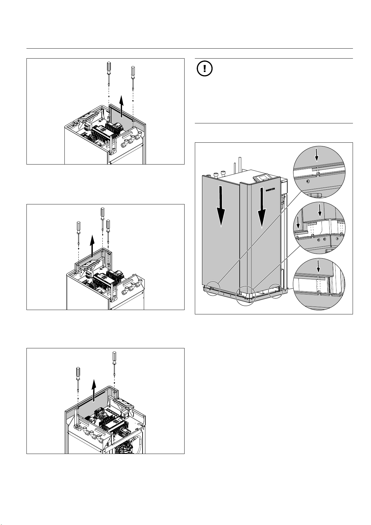
Undo and remove the two xing screws for the left-
»
hand appliance casing panel, inside the control box.
Lift the left-hand appliance casing panel up and away.
»
Material damage
When the appliance casing has been disassembled, sensitive components are fully exposed.
Assemble the appliance casing as soon as
»
there is nothing that needs doing inside the
appliance.
During the building phase, provide the appli-
»
ance with additional protection from dirt and
dust with a suitable covering.
10 .1.4 Assembling the appliance casing
11_02_200_214_01_008
Undo and remove the three xing screws for the front
»
appliance panel, inside the control box.
Lift the front appliance casing panel up and away.
»
Undo and remove the two xing screws for the right-
»
hand appliance casing panel, inside the control box.
Lift the right-hand appliance casing panel up and
»
away.
11_02_200_214_01_009
Slide the left-hand and front appliance casing panels
»
down from the top along the frame of the appliance,
until the panels click into place at the bottom.
Ensure that both panels are fully engaged at the ve
»
positions along the bottom.
Secure both of these appliance casing panels with
»
screws at the xing points provided, inside the control
box.
11_02_200_214_01_010
982000-AIR-M2-M4-EN03.1 | www.ochsner.com 27
INSTALLATION | Appliance installation
i
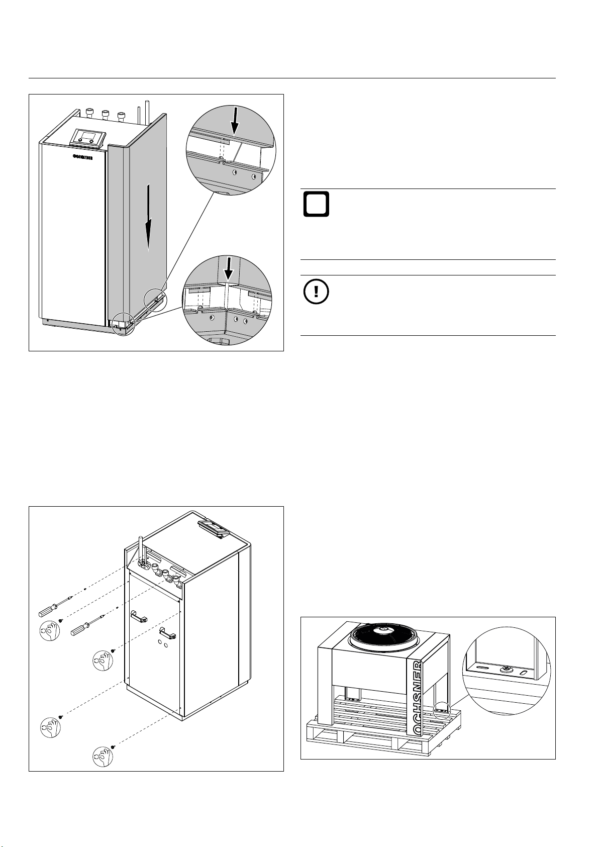
Slide the right-hand appliance casing panel down
»
from the top along the frame of the appliance, until
the panel clicks into place at the bottom.
10.2 Installing the outdoor unit
10 . 2 .1 Delivery and transportation
The appliance is delivered on a one-way pallet, wrapped
in lm. The appliance casing is assembled on delivery.
Information
Should you notice any transportation damage to
the appliance, you must report such damaged immediately when the delivery is unloaded. Claims
for transportation damage cannot be made subsequently.
Material damage
Protect the appliance from damage by using
»
transport belts.
When transporting, protect the appliance from
»
impact.
11_02_200_214_01_011
► The appliance is secured to the one-way (recyclable)
pallet of the transport packaging with screws.
► The transport packaging or one-way pallet is suitable
for transportation using a forklift truck.
Ensure that the panel is fully engaged at the three
»
points along the bottom.
Secure the appliance casing with screws at the xing
»
points provided, inside the control box.
Secure the appliance casing with screws at the rear
»
of the indoor unit.
► For level transportation to the installation location, the
appliance may remain in the transport packaging.
► Leave the appliance in the transport packaging or on
the one-way pallet for lifting and moving by crane or
forklift.
► The standard packaging of the appliance does not
provide protection against the weather or sea water.
► The appliance may be stored and transported only at
temperatures of between -20°C and +45°C.
► The appliance must be stored in its transport
packaging.
Please note the following when removing the transport
packaging:
11_02_200_214_01_006
Remove the transport packaging.
»
28 www.ochsner.com | 982000-AIR-M2-M4-EN03.1
11_02_200_504_01_007
INSTALL ATION | Appliance installation
11_02_200_504_01_006
i
Undo and remove the four woodscrews securing the
»
appliance to the one-way pallet.
10.2.2 Positioning the appliance
Position the appliance on the prepared foundations.
»
Secure the four legs of the outdoor unit on the foun-
»
dations, using four xing screws.
10.2.3 Disassembling the appliance casing
By removing the side casing panels on the outdoor unit,
you can gain access to the connection points for the refrigerant lines and to the terminal boxes for the electrical
control leads and power supply cables.
Undo and remove the two xing screws on the
»
underside.
Pull the side appliance casing panel down and away.
»
1
2
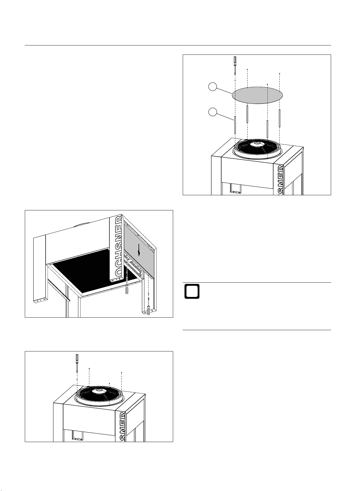
1 Round stainless steel plate
2 Mounting foot with threaded pin (4 pce, M5)
Attach the four mounting feet of the snow cover to the
»
outdoor unit, by screwing the threaded pins into the
four free screw holes in the ring-shaped casing part.
Attach the round stainless steel plate of the snow
»
cover to the four positioning feet (M5x12 mm, stainless steel).
10.2.4 Installing the snow cover
The snow cover for an outdoor unit fan can be retrotted.
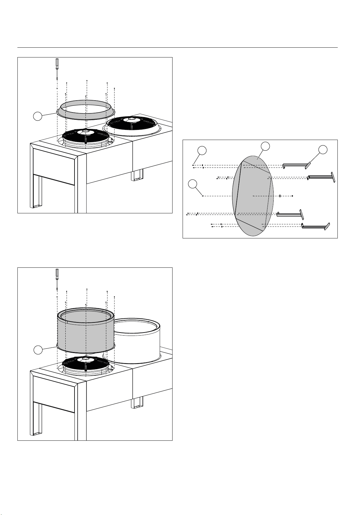
10.2.5 Fitting the cylindrical silencer
Information
The Super Silent Paket (SSP) exclusively available
ex works for a VHS-M outdoor unit reduces noise
by up to 3 dB. The Super Silent Paket consists of:
11_02_200_504_01_009
The cylindrical silencer from the super silent package
(SSP) can be retrotted. A retrotted cylindrical silencer
alone will reduce noise by about 1.5 dB.
11_02_200_504_01_005
- One cylindrical silencer per fan
- Reinforced casing insulation
- Shielded refrigeration technology
Undo and remove four of the eight xing screws on
»
the ring-shaped casing part for the fan (M5x12 mm,
stainless steel).
982000-AIR-M2-M4-EN03.1 | www.ochsner.com 29
INSTALLATION | Appliance installation
1
10.2.6 Installing the SSP snow cover
The SSP snow cover can be retrotted to an existing cy-
lindrical silencer on the outdoor unit.
Secure the four mounting feet to the round stainless
»
steel plate with screws (M5x12, 8 pcs).
Screw the safety bolt (M6x12, 1 pce) for the sound
»
absorbing mat into the centre of the stainless steel
plate.
1 Casing section for the fan
Undo and remove the eight xing screws (M5x12 mm,
»
stainless steel) on the ring-shaped casing part of the
fan.
Remove the ring-shaped casing part.
»
4
3
11_02_200_504_01_003
1 Round stainless steel plate with attached sound ab-
sorbing mat
2 Mounting foot with threaded rivet (4 pcs)
3 Safety bolt (M6x12, 1 pce) with washer and retaining
nut
4 Fixing screw (M5x12, 8 pcs) with plastic washer
Position the SSP snow cover on the upper edge of
»
the cylindrical silencer.
Ensure that the SSP snow cover is correctly aligned.
»
The cylindrical silencer has just one predrilled screw
hole for each mounting foot.
1
2
11_02_200_504_01_008
First, secure the four mounting feet of the SSP
»
snow cover to the cylindrical silencer, using the four
1
11_02_200_504_01_002
1 Cylindrical silencer
Position the cylindrical silencer over the fan. Ensure
»
that the assembly holes are correctly aligned.
Attach the cylindrical silencer to the casing panel of
»
the outdoor unit, using the eight xing screws (M5x12,
stainless steel).
30 www.ochsner.com | 982000-AIR-M2-M4-EN03.1
pre-drilled holes. Use self-tapping xing screws
(4.8x19 mm, stainless steel).
Secure the SSP snow cover through the remaining
»
four screw holes in the mounting feet that do not have
pre-drilled receiving holes. Use self-tapping xing
screws (4.8x19 mm, stainless steel).

INSTALL ATION | Appliance installation
i
i
i
i
11_02_200_202_01_016
1
Information
Ensure that the guard is easy to clean for maintenance purposes. A heavily soiled strainer can lead
to a high pressure safety shutdown or to a malfunc-
tion shutdown based on ow metering (heat sink).
Information
Ensure that the ow velocity in the pipe network
does not exceed 0.8 m/s, as this can cause increased noise emissions.
10 . 3 .1 Connecting the heating water
Before connecting the heat pump, ush the pipework
»
through with ltered ushing water in accordance with
standard procedures. Foreign bodies such as rust,
sealing material and swarf will impair the operational
reliability of the heat pump.
12
1 SSP snow cover
10.3 Connecting the heat sink system
Information
The hydraulic connection from the heat sink system
(WNA) to the heat pump may be made only by a
qualied contractor.
Information
For maintenance purposes, a cut-off valve should
be tted to every hydraulic line close to the connection point on the heat pump.
In the case of air/water heat pumps, an appropriately dimensioned heat pump buffer tank is essential, in order to
provide the necessary energy for defrosting the outdoor
unit.
► The pipe network and the pumps should be correctly
dimensioned for your heating system and according
to the technical data for your heat pump.
► A (manual) air vent valve must be tted at the highest
point in the pipework.
► At the lowest point in the pipework, t a drain pipe to
allow the system to be drained.
11_02_200_504_01_004
1 Heating water ow
2 Heating water/DHW return
Make the appropriate connections from the indoor
»
unit heating ow and heating return to the heating
system.
Ensure that the connection is tight.
»
When installing pipework, take care to prevent trans-
»
mission of vibration noise.
Quality of heating water
Use the corre ct ll water that is suit able for the compone nts
of your heating system. We recommend ll water prepared
according to Guideline VDI 2035-2.
A high pH value and low electrical conductivity in the ll
water will reduce to a minimum the risk of corrosion to iron
and copper materials, as long as there is also low oxygen
content. This will also minimise scaling (calcication).
► Ensure that no foreign bodies (dust, dirt etc.) can en-
ter the pipework.
► A guard (strainer) can be installed in the return line of
the heat pump to catch dirt.
982000-AIR-M2-M4-EN03.1 | www.ochsner.com 31
Fill water characteristics
pH value at 25°C 8.5 -10
Electrical conductivity at 25°C < 100 μS/cm
Oxygen content < 0.05 mg/l
Chloride < 30 mg/l

INSTALLATION | Appliance installation
i
i
i
Material damage
Unsuitable ll water can damage your system due
to scaling and corrosion.
If necessary, ensure that the ll water is pro-
»
fessionally softened and demineralised.
10.3.2 Safety valve drain
Information
The indoor unit has an internal safety valve (DHW,
heating).
Observe national and regional regulations re-
»
garding the design of the drain and prescribed
regular operational tests.
Information
The maximum operating pressure of the heat
transfer medium is 3 bar. However, due to closing
pressure differences, the safety valve may begin
to open from a pressure of 2.4 bar.
If the valve is triggered, the water exits via a hose on the
rear of the indoor unit.
The safety valve drain should be dimensioned such
»
that the water can drain unobstructed via an open
and readily visible waste water drain.
1
1 Drain and ll valve with hose screw connector (spe-
cial thread M21x1.5)
Information
The drain and fill valve has a special thread
(M21x1.5) for the hose screw connector.
Take care of the hose screw connector provid-
»
ed and keep it close to the heat pump.
2
1
3
11_02_200_202_01_027
Install the hose with a consistent fall to the drain.
»
Avoid kinking the hose.
10.3.3 Filling the heating system
On delivery, the 3-way switching module will be in the
“heating mode” position.
4
1 Drain and ll valve
2 Locking ring for closing and opening the drain and ll
valve
3 Hose screw connector (special thread M21x1.5)
4 Cover
Venting the heating system
On the AIR 7, AIR 11 and AIR 18 (M2 hydraulic variant)
indoor units, the multifunctional assembly (MFA) has a
quick-action air vent valve for venting the heating system.
Before venting, open the quick-action air vent valve
»
on the multifunctional assembly (MFA). Do this by
11_02_200_202_01_023
pulling the red cover on the valve.
Material damage
During venting, water can escape from the air outlet on the quick-action air vent valve.
Ensure that the electronics in the indoor unit
»
do not become wet.
11_02_200_202_01_028
You can nd information on subsequent manual switching
of the 3-way switching module in the controller operating
instructions (DHW circuit/relay test).
Fill the heating system with suitable ll water using
»
the drain and ll valve.
32 www.ochsner.com | 982000-AIR-M2-M4-EN03.1

INSTALL ATION | Appliance installation
i
i
11_02_200_202_01_017
1
1 Quick-action air vent valve on the multifunctional as-
sembly (AIR 7, AIR 11 and AIR 18)
Material damage
Close the quick-action air vent valve again
»
after venting by pressing the red cover on the
valve.
10.3.6 Cooling version
When used for cooling, all system components (pipes,
ttings) must be insulated against condensation build-up
using appropriate insulating materials. This is particularly
important on the ow line from the heat pump to the heat
pump buffer tank.
Especially in relation to cooling mode and defrost
»
mode, ensure adequate sizing of the hydraulic safety
devices.
Allow for a pressure maintaining device with appro-
»
priate charge pressure, adjusted for the operating
conditions.
Ensure that in cooling mode the appliance casing on
»
the indoor unit is fully and correctly installed (see „Assembling the appliance casing“ on page 27).
10.3.7 Connecting the DHW
11_02_200_202_01_029
The indoor unit is tted with a 3-way switching module for
switching between the DHW circuit and the heating circuit.
When conguring a DHW charging pump, take into account
the internal pressure differences in the plate heat exchang-
er (see „Specication“ on page 50).
10.3.4 Diaphragm expansion vessel (DEV)
► The indoor units for the AIR 7, AIR 11 and AIR 18
heat pumps are factory-tted with a 24 l diaphragm
expansion vessel for the heat sink system.
► The factory-set pre-charge pressure on the DEV is
1.5 bar.
Information
The set charge pressure on the DEV must not be
taken as correct but must be adjusted for the particular system.
Set the charge pressure on the DEV accord-
»
ing to the height of your system and the lling
pressure of your heating system.
10.3.5 Flow metering
A ow meter is installed on the heat sink side inside the
indoor unit of your heat pump. This unit measures the ow
rate in your heating system. Too low a ow rate will lead to
a safety shutdown of the heat pump.
12
1 DHW ow
2 Heating water/DHW return
Make the appropriate connections from the DHW
»
ow and DHW return on the indoor unit to the DHW
cylinder.
Information
The nominal ow rates for the heat sink system
(WNA) should be determined. Different ow rates
can lead to a reduction in the efciency of the heat
pump.
982000-AIR-M2-M4-EN03.1 | www.ochsner.com 33

INSTALLATION | Appliance installation
i
i
i
i
i
10.4 Electrical connection
10 . 4 .1 General
WARNING: Electrocution
Before commencing work on electrical connections
and installation, the heat pump system must be
isolated and voltage-free.
WARNING: Electrocution
Work on electrical connections and installation may
be conducted only by qualied contractors.
WARNING: Electrocution
Before commissioning, the necessary fault protection measures on the system and the earth
connection must be checked by an authorised
contractor.
Information
It is essential that the regulations of the responsible
power supply utility (PSU) and the applicable EN
standards be observed.
► Before commencing work to connect up the power
supply, the necessary activities dened in „Preparing
the electrical connections“ on page 22 must have
been completed.
► For the electrical connection, use the system principle
schematic appropriate to your heat pump system from
section „System schematic diagrams“ on page 68.
Undo and remove the four nuts on the two metal
»
plates at the cable entries.
Remove the two metal plates at the cable entries to
»
gain access to the cable strain reliefs.
Information
When tting the cables in the indoor unit, ensure
that subsequent connection work and soldering on
the refrigerant lines will not be obstructed by the
cables.
Information
For the shielded cables between the outdoor and
indoor units, use the shielding clamps provided on
the control box panel.
Information
For the cables inside the control box on the indoor
unit, use the cable strain reliefs provided.
Connect the lead for suction gas sensor S2 (coming
»
from the outdoor unit) to the terminal provided.
Connect the cable for the stepper motor of expansion
»
valve A (located in the outdoor unit) directly to the
free terminal on the expansion valve controller (EVD).
Be sure that each wire is connected correctly accord-
ing to its colour.
Connect the leads for defrost sensors TQE and TQA
»
directly to the OTE controller.
Connect the fan speed lead (0-10 VDC) directly to the
»
OTE controller.
10.4.2 Electrical connection of the indoor unit
Remove the control box cover (see „Disassembling
»
the appliance casing“ on page 26).
Connect the temperature sensors required by your
»
system (TA, TPO, TPM, TMK, TB) directly to the OTE
controller.
Connect the external pumps and servomotors re-
»
quired by your system (switching module, mixing
valve) directly to the OTE controller.
Information
For external pumps and servomotors, use the PE
terminals on the relevant OTE plug.
11_02_200_202_01_011
34 www.ochsner.com | 982000-AIR-M2-M4-EN03.1

INSTALL ATION | Appliance installation
11_02_200_202_01_014
1
2
1 X5 terminal for suction gas sensor S2
2 Terminal on expansion valve controller for the stepper
motor of expansion valve A
1: green
3: brown
2: yellow
4: white
11_02_200_202_01_013
OTE pin Description
7 Heating circuit circulation pump 1, direct (HCP 1)
8 Heating circuit circulation pump 2, mixed (HCP 2)
10 DHW auxiliary heater, only on M4 (DHWAH)
13/14 DHW charging pump ON/OFF (WWL)
15/16 Heating circuit mixing valve (MVH)
25/26 Buzzer fault output
40 0-10 VDC fan speed
41/4 2 Control elements (eBus)
43 Mixer sensor (TMK)
44 Outdoor temperature sensor (TA)
45 Top buffer sensor (TPO)
46 DHW sensor (TB)
49 Defrost sensor 1 (TQE)
50 Defrost sensor 2 (TQ A)
52 Bottom buffer sensor (TPM)
55 Building management system input
982000-AIR-M2-M4-EN03.1 | www.ochsner.com 35

INSTALLATION | Appliance installation
i
i
Information
For the cables inside the control box on the indoor
unit, use the cable strain reliefs provided.
Material damage
An external source of voltage at the sensor terminals can destroy the OTE controller.
Ensure that no 230 VAC or 400 VAC cables
»
are touching the sensor terminals on the OTE
controller.
Connect the power supply cable for the control circuit
»
(X3).
Connect the power supply for the main power circuit
»
(X1).
Connect the power supply for the electric booster
»
heater, if present (KM2, X8).
Information
Connect the PE conductor from the power cables
to the earth rail in the control box.
WARNING: Electrocution
When the appliance power supply is on, there will
always be 230 VAC at the PSU signal contact.
When using the PSU signal contact („PSU signal contact“
on page 24), please note the following:
Remove the factory-tted clamp on X3 (LS/21).
»
Connect the cable for the PSU signal contact to X3
»
(L S/21).
KM2
Terminal Description
X1 L1/L2/L3/N Connection from main power circuit (compres-
L/N/PE Connection from main power circuit (compres-
X2 L1/ N Connection for fan power supply (for outdoor
X2 TK1/TK2 Fan fault message
X3 L/N Mains connection for control circuit (OTE)
X3 LS/21 PSU signal contact
KM2 L1/L2/L3 Mains connection for the electric booster
X8 N/N/N
sor and fan) to three -phase alternating current
sor and fan) to single phase alternating current
unit)
heater (comprising three individual heating
elements)
10.4.3 Electrical connection of the outdoor unit
The outdoor unit receives its power supply via the indoor
unit.
Remove the side casing panel from the outdoor unit
11_02_200_202_01_012
»
to gain access to the terminal box (see „Disassem-
bling the appliance casing“ on page 26).
Connect the fan power supply in the terminal box.
»
Connect the lead for the defrost sensors (TQE, TQA).
»
Connect the fan speed lead (0-10 VDC). Make sure
»
that the polarity of the lead is correct.
Connect the lead for suction gas sensor S2 to the ter-
»
minal provided.
Connect the cable for the stepper motor of expan-
»
sion valve A (located in the outdoor unit). Be sure
that each wire is connected correctly according to its
colour.
11_02_200_202_01_015
36 www.ochsner.com | 982000-AIR-M2-M4-EN03.1

INSTALL ATION | Appliance installation
i
7
6
5
4
3
1 Fan fault message (TK1/TK2)
2 Fan power supply (L/N/PE)
3 Stepper motor of expansion valve A (1/2/3/4)
4 Suction gas sensor S2
5 Defrost sensor TQE (OTE pin 49/GND)
6 Defrost sensor TQA (OTE pin 50/GND)
7 Fan speed (0-10 VDC/GND)
8 Earth rail
8
1
2
10.5 Connecting heat source system
WARNING: Burns
Work on the refrigerant circuit may be carried out
only by an authorised and suitably qualied contractor. Refrigerant can cause burns to the skin.
When handling refrigerant, wear appropriate
»
gloves and protective glasses.
The following activities on air/water heat pumps must be
carried out by OCHSNER Customer Service or by a cus-
tomer service partner authorised by OCHSNER.
► Connecting the previously laid refrigerant lines.
► Conducting leakage tests on the refrigerant lines.
► Emptying the refrigerant lines.
► Insulating the refrigerant lines around the connection
points on the indoor and outdoor units.
► Filling the system with the correct refrigerant accord-
ing to OCHSNER guidelines.
Information
The system installer must ensure that noise insu-
lating pipe xings for the refrigerant lines and the
11_02_200_504_01_001
10 . 5 .1 Connecting the refrigerant lines
seals on the wall outlets are correctly tted.
Material damage
Incorrect or premature opening of the pipe connections and cutting of the refrigerant lines can allow
dirt and moisture to enter the refrigerant circuit.
Do not open the connections on the indoor
»
or outdoor units until just before installing the
refrigerant lines.
Cut the refrigerant lines with a suitable pipe
»
cutte r.
Prevent swarf from contaminating the pipe
»
connections and refrigerant lines.
Flush the refrigerant lines fully with nitrogen.
»
The refrigerant circuits on both the outdoor and indoor
units are lled with nitrogen at the factory. Please note the
following when installing the refrigerant lines:
Use the largest possible pipe bends to avoid high
»
pressure losses.
Use suitable sound-insulating pipe xings to secure
»
the refrigerant lines.
Do not install the pipe xings in the vicinity of bends
»
in the pipes.
Ensure that no strain can be exerted on soldered
»
joints.
982000-AIR-M2-M4-EN03.1 | www.ochsner.com 37

INSTALLATION | Appliance installation
i
i
2
1 Liquid line (refrigerant)
2 Suction gas line (refrigerant)
Ensure that the necessary preparatory work on refrig-
»
erant lines underground or in open air has been fully
completed.
Open up the connections for the liquid and suction
»
gas lines on the indoor and outdoor units using a suitable pipe cutter.
Connect the liquid and suction gas lines to the indoor
»
and outdoor units of the heat pump system.
1
10.5.3 Filling the refrigerant circuit with refrigerant
Empty the refrigerant lines.
»
Allow the refrigerant to ow into the refrigerant circuit.
»
Material damage
Operating the heat pump with too little or no refrigerant will damage the appliance.
10.5.4 Insulating the refrigerant lines
11_02_200_202_01_018
Insulate refrigerant lines with suitable insulating mate-
»
rial wherever they are still exposed to the air between
the indoor and outdoor units, to prevent formation
of condensation. When passing through open air
outside, the insulating material must also have UV
protection.
Information
Insulation used beneath the soil must be made of
a closed-cell material. Otherwise, the thermal insulation of the material will be impaired.
When soldering, ensure that neither moisture nor dirt
»
can penetrate into the refrigerant lines. When soldering, always use forming gas.
Ensure that soldered joints are properly sealed.
»
10.5.2 Checking for leak tightness
After the refrigerant lines have been installed, the leakage
test on the refrigerant circuit is carried out.
Information
Nitrogen can become trapped in magnetic valves
and expansion valves in the refrigerant circuit.
Before carrying out the leakage test, open all
»
magnetic valves and expansion valves in the
refrigerant circuit.
Evacuate the refrigerant lines.
»
Use a suitable medium to carry out the leakage test
»
according to standard regulations.
38 www.ochsner.com | 982000-AIR-M2-M4-EN03.1

INSTALL ATION | Commissioning
11_02_200_202_01_022
i
11. Commissioning
OCHSNER Customer Service or an authorised customer service partner must be requested to commission the
system. In order to be allocated an appointment, a completed and signed commissioning form must be provided.
Commissioning appointments must be requested at least
two weeks in advance.
11.1 Before switching on for the rst time
The heat pump has no separate on/off switch. In an emer-
gency, the system must be shut down via the specied
safety equipment. The safety equipment must be accessible so that an emergency shutdown can be performed
at any time.
WARNING: Electrocution
First-time start-up of electrical systems is permitted
only in the presence of a qualied contractor.
Make sure that no persons can be put at risk during
»
the rst start-up.
Make sure that the heat sink system (heating and
»
DHW production) has been connected to the heat
pump.
11.3 Adjusting the ow rate
The nominal ow rate of the heat sink system must be
determined in each operating mode (DHW charging, heat-
ing, cooling mode via separate cooling heat pump buffer
tanks etc.). The ow rate is measured using the installed
ow met er. The measured values can be read off from the
master controller display on the indoor unit.
The ow rate of the heat sink system is adjusted using the
adjusting screw on the heat generator pump (HGP). To
enable correct hydraulic adjustment, in particular during
combined heating or heating/cooling and DHW heating
modes, the appropriate balancing valves must be installed
and the system regulated accordingly.
Make sure that the hydraulic system is lled with
»
water.
Make sure that the system has been fully vented.
»
Make sure that the electrical installation has been
»
carried out and completed professionally.
Material damage
Operating the circulation pumps without water in
the system will destroy the pumps.
The power supply to the main power circuit (compressor)
must not be switched on until the refrigerant circuit has
been lled with refrigerant and the hydraulic system with
the correct medium.
11. 2 Testing the control circuit
Once all the above conditions have been checked, the power supply to the control circuit (OTE controller, 230 VAC)
can be switched on so that the individual functions can
be tested.
Check all of the sensors and their values for
»
plausibility.
1
1 Heat generator pump (HGP)
Information
To be able to change the ow rate in the heat sink
system, you will have to turn the adjusting screw
on the heat generator pump.
Remove the front casing panel from the indoor
»
unit to gain access to the heat generator pump
(see „Disassembling the appliance casing“ on
page 26).
Switch on the heat generator pump via the relay test
»
menu on the master controller.
Check all of the controller outputs used on your hy-
»
draulic system for correct function.
982000-AIR-M2-M4-EN03.1 | www.ochsner.com 39

INSTALLATION | Commissioning
HEIZKREIS 1
ESC
HEIZKREIS 2
WARMWASSERKREIS
WAERMEPUMPE
ENTER
Einstellungen
Relaistest
ESC
ENTER
Betriebswahl
Betriebsdaten
MENUE
ESC
Umlenkventil Kü
0
ESC
Wärmeerzeugerpu
0
0
SOLL Verdichter
ENTER
Wärmequellenpu
0
ESC
ENTER
100%
Wärmeerzeugerpumpe
MENUE
ESC
HEIZKREIS 1
ESC
HEIZKREIS 2
WARMWASSERKREIS
WAERMEPUMPE
ENTER
Betriebswahl
Betriebsdaten
Einstellungen
Relaistest
ESC
ENTER
ESC
ENTER
Heizenergie MWh
0
Heizleistung
0
Heizenergie kWh
0
Volumenstrom Wä
27
Volumenstrom Wärmenut-
zung
27.4 l / min
ESC
Mo 09 .01.17 10:02
-12.5C 22°C 52.5°C
32.5°C
Betriebsbereit
Ready for operation
OCHSNER OTE
HEATING CIRCUIT 1
HEATING CIRCUIT 2
DHW CIRCUIT
HEAT PUMP
ESC
WAERMEPUMPE
ESC
MENU
Hauptmenü
Main menu
HE AT PUMP
ENTER
MENU
Mo 09 .01.17 10:02
-12.5C 22°C 52.5°C
32.5°C
Betriebsbereit
Ready for operation
OCHSNER OTE
HEATING CIRCUIT 1
HEATING CIRCUIT 2
DHW CIRCUIT
HEAT PUMP
ESC
WAERMEPUMPE
ESC
MENU
Hauptmenü
Main menu
HE AT PUMP
ENTER
MENU
WARMWASSERKREIS
HE AT PUMP
Operation mode
Operating data
Settings
Relay test
ESC
HE AT PUMP
WAERMEPUMPE
01-022
01-022 Heat generator 0
01-076
01-076 TARGET compres
01-077
01-077 Heat source pump/ 0
01-078
01-078 Refrigerant circuit 0
ESC
01-022 H EAT PUMP
01-022 WAERMEPUMPE
Heat generator pump
ENTER
- 0
ENTER
100%
ESC
ENTER
11_01_200_701_01_01_002
WAERMEPUMPE
HE AT PUMP
Operation mode
Operating data
Settings
Relay test
ESC
HE AT PUMP
WAERMEPUMPE
21-002
21-002 Flow rate heat sink 27
23-001
23-001 Heating energy 0
23-010
23-010 Heating energy 0
23-003
23-003 Heating output 0
ESC
21-002 H EAT PUMP
21-002 WAERMEPUMPE
Flow rate heat sink
ENTER
ENTER
27.4 l/m in
ESC
ENTER
11_01_200_701_01_01_003
Read off the measured ow rate on the master con-
»
troller display.
40 www.ochsner.com | 982000-AIR-M2-M4-EN03.1
Adjust the ow rate to its correct level by turning the
»
adjusting screw on the heat generator pump.

INSTALL ATION | Commissioning
AIR 7 AIR 11 AIR 18
Hydraulic variant M2 M2 M2
Connection dimension DN 32 (1 1/4”) male DN 32 (1 1/4”) male DN 32 (1 1/4”) male
Heat sink system circulation pump
(heat generator pump)
Pump head [mbar] 776 776 783 6 51 762 774 499 611 690 766
Spread at L2/W35 [K] 5 7 10 5 7 10 5 6 7 10
Flow rate [m
Internal pressure loss (M2-1) [mbar] 109 56 27 205 104 51 324 225 165 81
Residual head I (M2-1) [mbar] 657 720 756 446 658 722 175 386 525 685
Addnl 3-way switching module [mbar] external DN32 kvs16 external DN32 kvs16 external DN32 kvs16
Pressure loss [mbar] 5 2 1 11 6 3 19 13 10 5
Residual head II (M2-1) [mbar] 652 718 754 435 652 719 156 372 515 680
Yonos Para HPS 25/7.5 Yonos Para HPS 25/7.5 Yonos Para HPS 25/7.5
internal internal internal
3
/h] 1 .1 0.79 0.55 1.7 1.21 0.85 2.2 1.83 1.57 1.1
100% 70% 50% 100% 70% 50% 10 0% 83% 70% 50%
External plate heat exchanger
(PHE) for DHW
Primary pressure loss, side A (HP) [mbar] 64 33 16 65 33 16 20 14 10 5
Primary pressure loss, side B
(DHW)
Residual head III: heating [mbar] 586 684 738 374 621 704 149 368 512 678
Residual head III: heating/cooling
incl. additional external 3-way
switching module (M2-1)
Hydraulic variant M4 M4 M4
Connection dimension DN 40 (1 1/2”) male DN 40 (1 1/2”) male DN 50 (2”) male
Heat sink system circulation pump
(heat generator pump)
Pump head [mbar] 686 728 726 577 714 727 929 1052 113 9 1124
Spread at L2/W35 [K] 5 7 10 5 7 10 5 6 7 10
Flow rate [m
Internal pressure loss (M4-1) [mbar] 330 168 82 464 237 116 820 569 418 205
Internal pressure loss (M4-4) [mbar] 234 120 59 304 155 76 523 363 267 131
Residual head I (M4-1) [mbar] 356 560 643 113 478 611 109 482 721 931
Residual head (M4-4 for cascade) [mbar] 452 609 667 273 559 651 406 689 873 10 05
Addnl 3-way switching module [mbar] External DN 40 kvs25 External DN 40 kvs25 External DN 50 kvs40
Pressure loss [mbar] 18 9 5 31 16 8 23 16 11 6
Residual head II (M4-1) [mbar] 338 551 638 82 462 603 87 466 710 925
Residual head (M4-4 for cascade) [mbar] 434 600 662 242 543 643 384 673 862 999
[mbar] 71 36 18 72 37 18 26 18 13 7
[mbar] 588 685 738 370 619 703 136 359 505 675
3
PHE 2007, A=1”, B=1” PHE 2007, A=1”, B=1” PHE 5007, A=1 1/4”, B=1”
AIR 23 AIR 29 AIR 41
Stratos Para 25/1-8 Stratos Para 25/1-8 Stratos Para 25/1-12
internal internal internal
/h] 3.4 2.43 1.7 4.4 3.14 2.2 6 5.00 4.29 3
100% 70% 50% 100% 70% 50% 10 0% 83% 70% 50%
External plate heat exchanger
(PHE) for DHW
Primary pressure loss, side A (HP) [mbar] 37 19 9 62 32 16 65 45 33 16
Primary pressure loss, side B
(DHW)
Residual head III: heating [mbar] 308 536 631 33 437 591 19 420 675 909
Residual head III: heating/cooling
incl. additional external 3-way
switching module (M4-1)
Residual head III (M4-4) [mbar] 397 5 81 653 180 512 628 319 628 828 983
982000-AIR-M2-M4-EN03.1 | www.ochsner.com 41
[mbar] 48 24 12 80 41 20 90 63 46 23
[mbar] 301 532 629 20 431 588 22 421 676 909
PHE 5007, A=1 1/4”, B=1” PHE 5007, A=1 1/4”, B=1” PHE 9507, A=2”, B=2”

INSTALLATION | Commissioning
11. 4 Heat generator pump (HGP)
Yonos Para HPS 25/7.5 (AIR 7, AIR 11, AIR 18)
Stratos Para 25/1-8 (AIR 23, AIR 29)
12_05_908_01_001
Stratos Para 25/1-12 (AIR 41)
12_05_908_02_001
42 www.ochsner.com | 982000-AIR-M2-M4-EN03.1
12_05_908_03_001

INSTALL ATION | Commissioning
i
i
11.5 Necessary conditions for commissioning
Before commissioning, the system installer must ensure
the following points:
► The design and installation of the system have been
approved by OCHSNER.
► The OCHSNER guidelines have been observed
(system installed according to OCHSNER standard
hydraulic schemes or a special OCHSNER hydraulic
system).
► The system datasheet is available and has been fully
and correctly completed.
1. The heat sink system is fully ready (heating and
DHW heating).
► The hydraulic pipework has been correctly di-
mensioned and installed such that the required
nominal ow rates can be set.
► The heat sink system has been ushed, lled and
vented according to the required standards.
► The quality of the system ll water is assured to
meet the required standards (VDI 2035).
► Operating pressure has been set and the system
temperature and buffer temperature lie between
20°C and 30°C at the time of commissioning.
► The necessary safety devices are in place and
have been adjusted and checked according to system requirements.
► A DHW cylinder is present and has been lled for
commissioning.
► All shut-off valves have been opened, adjusted
and checked.
► The ow meter has been checked for correct
functioning.
► The system has been hydraulically balanced.
2. The heat source system has been prepared.
► The hydraulic pipework has been correctly di-
mensioned and installed such that the required
nominal ow rates can be set.
► In the case of air/water and direct evaporation/
water heat pumps, if the routing of the connection lines by the system installer has been
contractually agreed:
Ensure that the refrigerant lines between the
indoor and outdoor units have been correctly
routed in accordance with refrigeration engineering guidelines. The refrigerant lines have been
correctly channelled through the wall outlets with
some surplus length between the connections at
the indoor and outdoor units.
► In the case of brine/water heat pumps:
The system pressure and addition of frost protection additive (between -12°C and -15°C) have
been assured. The heat source system has been
ushed, lled and vented according to standards.
► In the case of water/water heat pumps:
All lters have been checked and cleaned. The
water quality is in accordance with OCHSNER
guidelines.
Information
OCHSNER will accept no liability for damage (e.g.
to plate heat exchangers) caused by poor water
quality.
3. The electrical installation has been completed.
Information
Provisional electrical installations are not permissible and will lead to commissioning being cancelled.
► Electrical connection and installation work has
been carried out, checked and completed in accordance with national and regional regulations.
► A safety device that will shut down across all poles
has been provided on every supply (compressor,
heat source pump and controller). Every additional
heat generator is also provided with its own safety
device.
► The three-phase supply has been checked to en-
sure a clockwise rotating eld.
4. On site requirements
► An authorised and technically competent repre-
sentative of the system installer (the heating or
electrical contractor) is present along with the system user during the commissioning.
► The necessary safety devices are in place and
have been adjusted and checked according to system requirements.
► The wall outlet has been properly sealed.
982000-AIR-M2-M4-EN03.1 | www.ochsner.com 43
► Customer-specic controller settings are available
(heating curve and functional logic, according to
system datasheet).
► Where connections are in a duct or on the roof, an
assistant has been provided by the customer.
► Climbing aids and/or fall protection (compliant
attachment points) have been provided on site in
accordance with the required standards.

INSTALLATION | Commissioning
i
i
i
► Vehicle access to the heat pump system is
available.
Information
OCHSNER Customer Service or its customer ser-
vice partner carries out customer-specic settings
according to the details on the system datasheet.
If the system installer is not present during commissioning or if a fully completed system datasheet
is not available, the system is put into operation
using the control factory settings. OCHSNER will
accept no responsibility for any faulty operation
(too low a heating curve, too high a bivalent point,
etc.). Any additional work required will be charged
to the system installer.
11. 6 Commissioning the system
Before commissioning, the requirements set out in section
11.5 “Necessary conditions for commissioning” must be
met.
Commissioning is carried out by OCHSNER Customer
Service or by a customer service partner authorised by
OCHSNER. The OCHSNER commissioning guidelines
apply.
Information
If the system is operated without technically correct
commissioning in accordance with the OCHSNER
guidelines, all warranty claims will be invalid.
Information
Special work such as system venting, connecting
electrical cables, additional training etc., which is
not included in OCHSNER‘s scope of delivery, will
be invoiced separately.
Activities carried out by OCHSNER:
► Checking that the system has been installed accord-
ing to OCHSNER guidelines. In commissioning the
system, OCHSNER offers no warranty regarding the
ability to meet the heat demand of the building to be
heated.
► Functional testing of the heating circuit (system
pressure, function of diaphragm expansion vessel,
quantity settings). Responsibility for the system remains with the system installer.
► Checking ow rates.
► Checking that all shut-off valves are open.
► Checking the electrical connections to the system
components including all required safety devices.
► In the case of air/water and direct evaporation/water
heat pumps (depending on contractual terms):
► Version 1:
Where connecting lines have been laid as contractually agreed by the system installer. OCHSNER
Customer Service is responsible for:
- Connecting the previously laid refrigerant lines.
- Conducting leakage tests on the refrigerant
lines.
- Emptying the refrigerant lines.
- Insulating the refrigerant lines around the connection points on the indoor and outdoor units.
- Filling the system with the correct refrigerant
according to OCHSNER guidelines.
► Version 2:
Where connection lines have been laid and the
technical installation of the refrigerant circuit carried out by OCHSNER Customer Service.
44 www.ochsner.com | 982000-AIR-M2-M4-EN03.1

INSTALL ATION | Commissioning
i
► Checking that the 3-phase supply is correctly phased
with a clockwise rotating eld.
► Switching on the main power circuit (3-phase supply
to heat pump).
► Switching on the power supply to the control circuit.
► Conguring the system using the commissioning
assistant.
► Checking the sensor conguration.
► Conducting a relay test on the outputs.
► Making customer-specic settings on the heat pump
system.
► Producing a commissioning report and completing
the entries in the service book.
► Handing the system over to the system user or end
customer.
► Explanation of the basic functions of the heat pump
system (controller operation, etc.).
11.7 Decommissioning
You do not need to switch off your heat pump system in
the summer. The heat pump control unit changes over automatically between summer and winter.
Material damage
If the power supply to your heat pump system is
switched off, frost protection of the system cannot
be guaranteed.
You should not switch off the power supply
»
to your heat pump, even outside the heating
period.
Should you wish to deactivate your heat pump system, then
switch off the system using the master controller. This way,
safety functions such as frost protection remain enabled.
Material damage
If the power supply to the heat pump system is
interrupted and there is a risk of frost, drain the
system on the water side.
Information
OCHSNER Customer Service will provide an explanation of the basic functions of the heat pump
system (controller operation, etc.). If the system
user is not present on commissioning, the system
installer will assume responsibility for this explanation. Instruction on the functionality of the overall
system is the responsibility of the system installer.
982000-AIR-M2-M4-EN03.1 | www.ochsner.com 45

INSTALLATION | Troubleshooting
i
12. Troubleshooting
Information
Resolving faults and making changes to settings
on the heat pump system may only be carried out
by qualied contractors. Standard settings for the
controller are set by OCHSNER Customer Service
as part of the commissioning process. The system
user and contractual partner is responsible for any
further corrections and settings to programs.
Problem Cause Solution
Too little DHW is available or
the central heating system is
too cold.
The appliance is leaking
water.
The heating system does not
heat up, no fault message.
The heat pump is only
producing DHW and is not
providing heating, or is doing
so too late.
DHW temperature is not or is
no longer being reached.
Heat pump runs continuously
but yields only low temperatures, and there are traces of
oil in the appliance.
Flow rate too low The minimum flow rate at the heat
The power supply to the appliance
has been cut off.
The drain for the safety valve is
blocked.
PSU shutdown Check individual room controls, vent the heating circuit, open valves,
Energy transfer to the heating circuits
is interrupted or too low
Power failure
DHW priority
DHW target temperature is too high Check the DHW target temperature
Pasteurisation mode Use time program, install electric immersion heater for DHW
DHW circulation line Reduce flow rate and use time clock
DHW heat exchanger scaled up Notify heating contractor, clean heat exchanger, descale
Heat exchanger for DHW is too small. Increase size of heat exchanger
Heat exchanger is scaled up Descale heat exchanger
Sensor incorrectly positioned Correctly position sensor
Pipework too small Install pipes with larger diameters
Faulty DHW sensor Replace DHW sensor
DHW charging pump is faulty Replace DHW charging pump
DHW charging pump output level set
too low
3-way switching module is faulty Replace 3-way switching module
Refrigerant leak, refrigerant line not
leak tight
pump is not being reached.
Check the safety device on the main distributor board for your house.
Switch the safety device back on. If the safety device triggers again after
being switched back on, contact a qualified contractor or OCHSNER
Customer Service.
Clean the safety valve drain.
check heating circuit circulation pump, increase the output level of the
heating circuit circulation pump, check fuses
Set higher output levels
Switch off heat pump, notif y OCHSNER Customer Service
System pressure too low: check pressure maintenance equipment. Buffer
charging pump is faulty, 3-way switching module is faulty
12 .1 Fault messages on the master controller
► In the event of a fault, the relevant fault messages will
be displayed on the controller as “Er XXX”.
► If the high limit safety cut-out is triggered, this will
not be displayed with a fault message on the master
controller.
In the following table, the possible fault messages are listed
together with the associated code or fault history code.
Fault messages with an associated fault history code are
stored and can be read off again later, even when no fault
is present. Stored fault messages are listed in the “Service
Report” menu under the “Error data” submenu.
46 www.ochsner.com | 982000-AIR-M2-M4-EN03.1

INSTALL ATION | Troubleshooting
Code Fault code
history
115 Er 01: DHW sensor faulty Replace sensor
116 Er 10: Outside sensor faulty Replace sensor
117 Er 14: Mixer sensor faulty Replace sensor
124 Er 20: TWR sensor faulty Replace sensor
120 Er 22: TPM or TWR shutdown sensor faulty Replace sensor
136 Er 23: TPV sensor faulty Replace sensor
118 Er 24: Buf fer sensor faulty Replace sensor
114 Er 29: TWV sensor faulty Replace sensor
11 11 Er 30: Phase monitor Check power supply
134 Er 32: THG sensor faulty Replace sensor
138 Er 33: High pressure sensor faulty Check sensor
137 Er 34: Low pressure sensor faulty Check sensor
5 5 Er 36: High pressure Deficient heat distribution, faulty circulation pump, valve closed or air in the
18 18 Er 37: Low pressure Lack of source energy, lack of refrigerant, expansion valve, check refrigerant
16 16 Er 38: Hot gas Expansion valve, lack of refrigerant, target temperature too high, check re-
10 10 Er 39: Compressor motor protection Motor overload relay, phase fault/overload, source temperature too high,
8 8 Er 42: Heat sink frost protection Deficient heat distribution, faulty circulation pump, valve closed or air in the
Er 46: TSG sensor faulty Replace sensor
9 9 Er 47: Defrost fault Too little de-icing energy, evaporator/sensor, check refrigerant circuit (by
129 129 Er 48: TQE sensor/Evaporator 1 is faulty Replace sensor
130 130 Er 49: TQA sensor/Evaporator 2 is faulty Replace sensor
12 12 Er 50: Expansion valve Check function of electronic expansion valve (by OCHSNER)
1 1 Er 56: Heat source flow rate Lack of source energy, heat source pump/filter, flow rate at heat source too
2 2 Er 57: Heat source frost protection Lack of source energy, source temperature too low, check heat source,
3 3 Er 58: Heat source motor protection Check motor protection, check wiring to motor, motor overload relay, phase
143 143 Er 59: TW V + TWR sensor break Check sensor
144 144 Er 60: TQA + TQE sensor break Check sensor
42 42 Er 71: Bus fault, room remote control Check eBus wiring
30 30 Er 80: Heat generator 1 address Check addressing
31 31 Er 81: Heat generator 2 address Check addressing
32 32 Er 82: HG 3 address Check addressing
33 33 Er 83: HG 4 address Check addressing
34 34 Er 84: HG 5 address Check addressing
35 35 Er 85: HG 6 address Check addressing
36 36 Er 86: HG 7 address Check addressing
37 37 Er 87: HG 8 address Check addressing
20 20 Er 91: Heat sink flow rate Water pressure too low, circulation pump faulty, valve closed/air in system,
21 21 Er 90: Overheating Check refrigerant circuit (by OCHSNER Customer Service)
98 98 Er 98: Auxiliary heat generator running as
104 10 4 Er104: Sum fault, heat pump OCHSNER Customer Service
108 10 8 Er108: Outdoor unit, general Check wiring
109 10 9 Er109: Compressor overheating Automatic acknowledgement
100 10 0 Er200: Condensation temperature too low Check refrigerant circuit (by OCHSNER Customer Service)
102 102 Er 202: Evaporation temp. too low Check refrigerant circuit (by OCHSNER Customer Service)
103 103 Er 203: Evaporation temp. too high Check refrigerant circuit (by OCHSNER Customer Ser vice)
240 240 Er240: OTE cannot recognise a Modbus
241 241 Er241: Modbus communication error Power shutdown? Check the wiring of the Modbus cable between indoor and
242 242 Er242: CAN bus communication fault Check wiring of CAN bus cable and Modbus cable (possible consequential
Display message Possible cause and solution
system, check hydraulics
circuit (by OCHSNER Customer Service)
frigerant circuit (by OCHSNER Customer Service)
check compressor in refrigerant circuit (by OCHSNER Customer Service)
system, check buffer charging pump or hydraulics
OCHSNER Customer Service)
low
check heat source pump/filter, clean water filter, submersible pump faulty
fault/overload, thermal cutout
check hydraulics
Check operation mode of heat pump
only heat generator
Check by OCHSNER Customer Service
PCB
outdoor units. Otherwise check by OCHSNER Customer Service
fault of Er 241), otherwise check by OCHSNER Customer Service
982000-AIR-M2-M4-EN03.1 | www.ochsner.com 47

INSTALLATION | Appliance maintenance
i
i
12.2 Reset high limit safety cut-out
If the temperature sensor of the high limit safety cut-out
registers a heating water temperature of over 85°C, the
power supply to the internal electric booster heater is cut
off.
Check whether the high limit safety cut-out has
»
triggered.
Check the ow rate of the heating water.
»
Remedy the source of the fault.
»
Press the reset button on the rear of the appliance to
»
reset the high limit safety cut-out. The reset button
can be reached by hand from the left-hand side.
1
13. Appliance maintenance
WARNING: Electrocution
For maintenance work, cut off the power supply to
the indoor and outdoor units of your heat pump.
Information
Ensure that the refrigerant circuit of your heat pump
is tested for leaks once a year (in acc. with Regulation (EU) no. 517/2014).
Ensure year-round access to soldered joints in
»
the refrigerant circuit.
Document the results of the leakage test in the
»
system test report.
We recommend arranging for an inspection and if necessary a service on the heat pump to be conducted once
a year. We draw your attention to the fact that statutory
regulations require regular testing of heating systems by
the system user.
The refrigerants used in OCHSNER heat pumps are
non-ammable, non-toxic and ozone neutral. Heat pumps
are refrigeration equipment and are subject to the provisions of the F-gas Regulations (Regulation (EU) no.
517/2014). OCHSNER Customer Service will be pleased to
help in carrying out maintenance and testing, in particular
as required by the F-gas Regulations. You can nd more
information at www.ochsner.com.
1 Reset button for high limit safety cut-out on rear of
appliance
We recommend testing the heating water system pressure
and correcting it if necessary (pressure too high/low).
We recommend adjusting the charge pressure in the diaphragm expansion vessel (DEV) on the system accordingly
(system height).
We recommend monitoring the ow rate of the heat sink
system (WNA) and if necessary the heat source system
(WQA) using the ow meters specied by OCHSNER.
We recommend that when non-routine work takes place
requiring relling (e.g. system alteration or pipe breakage),
a current water assessment be prepared and the heat sink
system be relled on the basis of this.
13 .1 Testing safety valve
11_02_200_202_01_021
Information
The indoor unit has an internal safety valve (DHW,
heating).
Observe the national and regional regulations
»
regarding the prescribed regular operational
tests.
Remove the left-hand appliance casing panel to gain
»
access to the internal safety valve (see „Disassembling the appliance casing“ on page 26).
To test, turn the red knob on the safety valve until wa-
»
ter emerges from the safety valve drain.
48 www.ochsner.com | 982000-AIR-M2-M4-EN03.1

INSTALL ATION | Appliance maintenance
11_02_200_202_01_025
Ensure that the safety valve is closed again after the
»
test.
1
1
1 Internal safety valve on AIR 7, AIR 11 and AIR 18
1 Internal safety valve on AIR 23, AIR 29 and AIR 41.
11_02_200_202_01_026
13. 2 Maintenance contract
OCHSNER offers a wide range of maintenance contracts.
You can nd more information at www.ochsner.com.
Benetsofamaintenancecontract
► Annual inspection fulls the statutory requirements
(of, for example, the F-gas Regulations).
► A correctly performed service not only helps to save
energy but also protects the environment.
► In addition, correct care of the heating system is
necessary to ensure many years of service life and
indeed to extend the service life of the system.
► For the system user, this reduces the risk of system
failure.
You can nd further information on customer service and
on the services offered under the maintenance contracts
at www.ochsner.com.
982000-AIR-M2-M4-EN03.1 | www.ochsner.com 49

INSTALLATION | Specication
14. Specication
14 .1 Heat pumps for three-phase alternating
current
14 .1.1 Data table
AIR 7 C11A AIR 11 C11A AIR 18 C11A
INDOOR UNIT:
Hydraulic variant M2-1/M2-2/M2-3/M2-4 M2-1/M2-2/M2-3/M2- 4 M2-1/M2-2 /M2-3/M2-4
Dimensions HxWxD [mm] 1286x600x680 1286x600x680 1286x600x680
Hydraulic connection DN 32 (1 1/4”) male DN 32 (1 1/4”) male DN 32 (1 1/4”) male
Weight [kg] 114 124 13 5
Casing colour Tiger white 29/11289/
grey RAL 7016
HEATING MODE PERFORMANCE DATA:
Standard point L10/W35
Heating output [kW] 6.8 11 16
Total power consumption / operating current [kW]/[A] 1.33 / 2.65 2.3 / 4.7 3 / 6.2
Coefficient of per formance EN 14511/EN 255 5.1 / 5.6 4.9 / 5.2 5.3 / 5.6
Operating point L7/W35
Heating output [kW] 6.4 10.2 15 .1
Total power consumption / operating current [kW]/[A] 1.33 / 2.65 2.3 / 4.5 3 / 6.2
Coefficient of per formance EN 14511/EN 255 4.8 / 5.3 4.5 / 4.7 5 / 5.3
Tiger white 29/11289/
grey RAL 7016
Tiger white 29/11289/
grey RAL 7016
Standard point A2/W35
Heating output [kW] 5.4 8.8 13. 2
Total power consumption / operating current [kW]/[A] 1.32 / 2.64 2.2 / 4.4 3 / 6.2
Coefficient of per formance EN 14511/EN 255 4.1 / 4.5 4 / 4.3 4.4 / 4.7
Standard point L-7/W35
Heating output [kW] 4.1 6.8 10.6
Total power consumption / operating current [kW]/[A] 1.28 / 2.6 2 / 4.2 3 / 6.1
Coefficient of per formance EN 14511/EN 255 3.2 / 3.5 3.3 / 3.6 3.6 / 3.8
Operating point L-10/W35
Heating output [kW] 3.7 6.2 9.9
Total power consumption / operating current [kW]/[A] 1.25 / 2.55 2 / 4.1 2.9 / 6
Coefficient of per formance EN 14511/EN 255 3 / 3.3 3.1 / 3.3 3.4 / 3.6
Operating point A2/W50
Heating output kW 4.7 7.9 12.3
Total power consumption / operating current [kW]/[A] 1.75 / 3.4 2.8 / 5.8 4 / 8.2
Coefficient of per formance EN 14511/EN 255 2.7 / 2.9 2.8 / 3 3.1 / 3.2
Operating point A2/W60
Heating output [kW] 4.3 7. 6 12.1
Total power consumption / operating current [kW]/[A] 1.95 / 3.6 3.2 / 6.6 4.4 / 9.1
Coefficient of per formance EN 14511/EN 255 2.2 / 2.4 2.4 / 2.5 2.8 / 2.9
COOLING MODE PERFORMANCE DATA:
Operating point A30/ W18
Cooling capacity [kW] 4.4 9.6 11.2
Total power consumption / operating current [kW]/[A] 1.34 / 2.8 3 / 6.2 3.3 / 6.8
Energy efficiency ratio EER 3.3 3.2 3.4
Operating point A30/ W7
Cooling capacity [kW] 3 .1 8.7 10.7
Total power consumption / operating current [kW]/[A] 1.39 / 2.9 2.9 / 6 3.3 / 6.8
Energy efficiency ratio EER 2.2 3 3.2
SPECIFICATION:
Phases/nominal voltage/frequency [~]/[V]/[Hz] 3/400/50 3/400/50 3/400/50
Output factor cos ϕ 0.7 0.7 0.76
Fuse C10A C10A C16A
Max. operating current [A] 5.4 7. 9 11.4
50 www.ochsner.com | 982000-AIR-M2-M4-EN03.1

INSTALL ATION | Specication
i
i
AIR 7 C11A AIR 11 C11A AIR 18 C11A
Max. starting current/max. with soft start [A] 27 / 13.5 40 / 20 64 / 32
Sound power level/sound pressure level (at 1 m distance) [dBA] 40.9 / 32.9 44.5 / 36.5 47.5 / 39.5
ELECTRIC BOOSTER HEATER (M2-1, M2-3):
Phases/nominal voltage/frequency [~]/[V]/[Hz] 3/400/50 3/400/50 3/400/50
Max. output [kW] 8.8 (2.9 / 2.9 / 2.9) 8.8 (2.9 / 2.9 / 2.9) 8.8 (2.9 / 2.9 / 2.9)
Max. operating current [A] 12.8 12.8 12.8
CONDENSER:
Type Plate heat exchanger Plate heat exchanger Plate heat exchanger
Material Stainless steel 1.4301 Stainless steel 1.4301 Stainless steel 1.4301
Quantity [pcs] 1 1 1
Max. refrigerant operating pressure [bar] 30 30 30
Max. heat transfer medium operating pressure [bar] 3 3 3
Heat transfer medium temperature differential [K] 5 5 5
Application range [°C] 65 65 65
Heat transfer medium Water Water Water
Test pressure [bar] 45 45 45
Heat transfer medium flow rate [m³/h] 1.1 1.7 2.2
Internal pressure differential [mbar] 109 205 324
Flow meter built-in built-in built-in
Heat sink circulation pump (heat generator pump) internal Yonos Para 25/7.5 Yonos Para 25/7.5 Yonos Para 25/7.5
Residual head I heat sink system, external, incl. flow meter
REFRIGERANT CIRCUIT:
No. of refrigerant circuits [pcs] 1 1 1
Heat transfer medium R407C R407C R407C
Refrigerant full charge [kg] 5.0 9.0 9.0
Defrost technology Hot gas Hot gas Hot gas
[mbar] 657 446 175
COMPRESSOR:
Type Fully hermetic/scroll Fully hermetic/scroll Fully hermetic/scroll
Quantity [pcs] 1 1 1
Output levels 1 1 1
Speed [rpm] 2900 2900 2900
Voltage/frequency [V ]/[Hz] 400 / 50 400 / 50 400 / 50
Max. operating current [A] 4 6.5 10
FAN (OUTDOOR UNIT):
Type Axial Axial Axial
Quantity [pcs] 1 1 1
Voltage/frequency [V ]/[Hz] 230 / 50 230 / 50 230 / 50
Power consumption [W] 23 40 68
Max. operating current [A] 1.40 1.40 1.40
EVAPORATOR (OUTDOOR UNIT):
Appliance type VHS-M 5 VHS-M 9 VHS-M 14
Dimensions HxWxD [mm] 1080x1290x960 1080x1290x960 1080x1290x960
Type Finned pipe Finned pipe Finned pipe
Quantity [pcs] 1 1 1
Weight [kg] 93 93 93
Fin pack material Copper/aluminium Copper/aluminium Copper/aluminium
Casing material Stainless steel, coated Stainless steel, coated Stainless steel, coated
Max. refrigerant operating pressure [bar] 30 30 30
Relative humidity [%] 80 80 80
Heat transfer medium temperature differential [K] 3.7 5.7 5.7
Air flow rate [m³/h] 2100 3000 4000
Application range min./max [°C] -24 / +40 -24 / +40 -24 / +40
Sound power level/sound pressure level [dBA] 48/20 52/23 54/26
Sound power level/sound pressure level (in silent mode) [dBA] 46/18 49/20 51/ 23
Information
Data on sound pressure levels refer to operation at
full load at a distance of 10 m (free space). Sound
pressure and sound power levels are given +/-3
dB(A).
982000-AIR-M2-M4-EN03.1 | www.ochsner.com 51
Information
Silent mode offers four separate time windows
during which the outdoor unit can be operated
with reduced sound levels. It is set via the OTE
controller.

INSTALLATION | Specication
AIR 23 C12A AIR 29 C12A AIR 41 C12A
INDOOR UNIT:
Hydraulic variant M4-1/M4-2/M4-3/M4-4 M4-1/M4-2/M4-3/M4-4 M4-1/M4-2/M4-3/M4-4
Dimensions HxWxD [mm] 1286x600x680 1286x600x680 1286x600x680
Hydraulic connection DN 40 (1 1/2”) male DN 40 (1 1/2”) male DN 50 (2”) male
Weight [kg] 148 160 164
Casing colour Tiger white 29/11289/
grey RAL 7016
HEATING MODE PERFORMANCE DATA:
Standard point L10/W35
Heating output [kW] 23.4 28.4 40
Total power consumption / operating current [kW]/[A] 4.6 / 9 5.8 / 11.8 8.2 / 16.7
Coefficient of per formance EN 14511/EN 255 5.1 / 5.4 4.9 / 5.2 4.9 / 5.1
Operating point L7/W35
Heating output [kW] 20.7 25.8 37. 2
Total power consumption / operating current [kW]/[A] 4.5 / 8.8 5.6 / 11.4 8.1 / 16.5
Coefficient of per formance EN 14511/EN 255 4.6 / 4.9 4.6 / 4.9 4.6 / 4.8
Standard point A2/W35
Heating output [kW] 17. 2 21.8 30.3
Total power consumption / operating current [kW]/[A] 4.1 / 8 5.2 / 10.6 7.4 / 15
Coefficient of per formance EN 14511/EN 255 4.2 / 4.4 4.2 / 4.4 4.1 / 4.4
Standard point L-7/W35
Heating output [kW] 13.7 17.5 25.1
Total power consumption / operating current [kW]/[A] 3.9 / 7.6 5 / 10.2 7.4 / 15
Coefficient of per formance EN 14511/EN 255 3.5 / 3.8 3.5 / 3.8 3.4 / 3.6
Tiger white 29/11289/
grey RAL 7016
Tiger white 29/11289/
grey RAL 7016
Operating point L-10/W35
Heating output [kW] 12 .8 16.3 23.4
Total power consumption / operating current [kW]/[A] 3.9 / 7.6 5 / 10.2 7.4 / 15
Coefficient of per formance EN 14511/EN 255 3.3 / 3.6 3.3 / 3.6 3.2 / 3.4
Operating point A2/W50
Heating output kW 16.8 21. 2 27.4
Total power consumption / operating current [kW]/[A] 5.3 / 10.3 6.6 / 13.4 8.8 / 17.9
Coefficient of per formance EN 14511/EN 255 3.2 / 3.4 3.2 / 3.4 3.1 / 3.3
Operating point A2/W60
Heating output [kW] 16.4 20.8 26.4
Total power consumption / operating current [kW]/[A] 5.8 / 11.3 7.3 / 14.8 9.3 / 18.9
Coefficient of per formance EN 14511/EN 255 2.8 / 3 2.8 / 3 2.8 / 3
COOLING MODE PERFORMANCE DATA:
Operating point A30/ W18
Cooling capacity [kW] 15.6 17.9 2 7. 2
Total power consumption / operating current [kW]/[A] 5.1 / 9.9 5.7 / 11.6 8.4 / 17.1
Energy efficiency ratio EER 3 .1 3 .1 3.2
Operating point A30/ W7
Cooling capacity [kW] 15.2 17.2 25.9
Total power consumption / operating current [kW]/[A] 5 / 9.8 5.6 / 11.4 8.3 / 16.9
Energy efficiency ratio EER 3 3.1 3.1
SPECIFICATION:
Phases/nominal voltage/frequency [~]/[V]/[Hz] 3/400/50 3/400/50 3/400/50
Output factor cos ϕ 0 .74 0.71 0.71
Fuse C20A C25A C25A
Max. operating current [A] 16.8 21.1 24.8
Max. starting current/max. with soft start [A] 101 / 50.5 99 / 49.5 127 / 63.5
Sound power level/sound pressure level (at 1 m distance) [dBA] 49.5 / 41.5 55.5 / 47.5 55.5 / 47.5
52 www.ochsner.com | 982000-AIR-M2-M4-EN03.1

INSTALL ATION | Specication
i
i
AIR 23 C12A AIR 29 C12A AIR 41 C12A
ELECTRIC BOOSTER HEATER (M4-1, M4-3):
Phases/nominal voltage/frequency [~]/[V]/[Hz] 3/400/50 3/400/50 3/400/50
Max. output [kW] 8.8 (2.6 / 3.0 / 3.2) 8.8 (2.6 / 3.0 / 3.2) 8.8 (2.6 / 3.0 / 3.2)
Max. operating current [A] 14 14 14
CONDENSER:
Type Plate heat exchanger Plate heat exchanger Plate heat exchanger
Material Stainless steel 1.4301 Stainless steel 1.4301 Stainless steel 1.4301
Quantity [pcs] 1 1 1
Max. refrigerant operating pressure [bar] 30 30 30
Max. heat transfer medium operating pressure [bar] 3 3 3
Heat transfer medium temperature differential [K] 5 5 5
Application range [°C] 65 65 65
Heat transfer medium Water Water Water
Test pressure [bar] 45 45 45
Heat transfer medium flow rate [m³/h] 3.4 4.4 6
Internal pressure differential [mbar] 330 464 820
Flow meter built-in built-in built-in
Heat sink circulation pump (heat generator pump) internal Stratos Para 25/1-8 Stratos Para 25/1-8 Stratos Para 25/1-12
Residual head I heat sink system, external, incl. flow meter
REFRIGERANT CIRCUIT:
No. of refrigerant circuits [pcs] 1 1 1
Heat transfer medium R407C R407C R407C
Refrigerant full charge [kg] 10.0 15.0 16.0
Defrost technology Hot gas Hot gas Hot gas
[mbar] 356 (M4-1)
452 (M4- 4)
113 (M4-1),
273 (M4- 4)
109 (M4-1),
40 6 (M 4-4)
COMPRESSOR:
Type Fully hermetic/scroll Fully hermetic/scroll Fully hermetic/scroll
Quantity [pcs] 1 1 1
Output levels 1 1 1
Speed [rpm] 2900 2900 2900
Voltage/frequency [V ]/[Hz] 400 / 50 400 / 50 400 / 50
Max. operating current [A] 14 18.3 22
FAN (OUTDOOR UNIT):
Type Axial Axial Axial
Quantity [pcs] 2 2 2
Voltage/frequency [V ]/[Hz] 230 / 50 230 / 50 230 / 50
Power consumption [W] 111 201 337
Max. operating current [A] 2.80 2.80 2.80
EVAPORATOR (OUTDOOR UNIT):
Appliance type VHS-M 19 VHS-M 25 VHS-M 35
Dimensions HxWxD [mm] 1080x2220x960 1080x2220x960 1080x2220x960
Type Finned pipe Finned pipe Finned pipe
Quantity [pcs] 1 1 1
Weight [kg] 136 175 180
Fin pack material Copper/aluminium Copper/aluminium Copper/aluminium
Casing material Stainless steel, coated Stainless steel, coated Stainless steel, coated
Max. refrigerant operating pressure [bar] 30 30 30
Relative humidity [%] 80 80 80
Heat transfer medium temperature differential [K] 4 5.9 5.9
Air flow rate [m³/h] 8000 8000 9800
Application range min./max [°C] -24 / +40 -24 / +40 -24 / +40
Sound power level/sound pressure level [dBA] 54/26 58/30 61/33
Sound power level/sound pressure level (in silent mode) [dBA] 52 / 24 54/26 57/2 8
Information
Data on sound pressure levels refer to a distance
of 10 m (free space). Sound pressure and sound
power levels are given +/-3 dB(A).
Information
Silent mode offers four separate time windows
during which the outdoor unit can be operated
with reduced sound levels. It is set via the OTE
controller.
982000-AIR-M2-M4-EN03.1 | www.ochsner.com 53

INSTALLATION | Specication
14 .1.2 Output diagrams
AIR 7 C11A
9
Y
8
7
6
5
4
3
2
1
0
-25 -23 -21 -19 -17 -15 -13 -11 -9 -7 -5 -3 -1 1357 9 11 13 15 17 19 21 23 25
X Air temperature [°C]
Y Heating output [kW], component tolerance/output tolerance ±10%
7
Y
6
5
4
3
4
Y
3
2
35°C
45°C
50°C
60°C
X
12_01_200_202_01_001 AIR_7_ C11A
2
1
0
-25 -21 -17 -13 -9 -5 -1 3 7 11 15 19 23
X
12_02_200_202_01_001 AIR_7_C11A
X Air temperature [°C]
Y Coefcient of performance (COP), component toler-
ance/output tolerance ±10%
54 www.ochsner.com | 982000-AIR-M2-M4-EN03.1
1
0
-25 -21 -17 -13 -9 -5 -1 3 7 11 15 19 23
X
X Air temperature [°C]
Y Power consumption [kW], component tolerance/out-
put tolerance ±10%
12_03_200_202_01_001 AIR_7_C11A

INSTALL ATION | Specication
12_01_200_202_01_002 AIR_11_C11A
35°C
45°C
50°C
60°C
12_03_200_202_01_002 AIR_11_C11A
AIR 11 C 11A
15
Y
14
13
12
11
10
9
8
7
6
5
4
3
-25 -23 -21 -19 -17 -15 -13 -11 -9 -7 -5 -3 -1 1 3 5 7 9 11 13 15 17 19 21 23 25
X Air temperature [°C]
Y Heating output [kW], component tolerance/output tolerance ±10%
Y
6
5
4
3
2
1
0
-25 -21 -17 -13 -9 -5 -1 3 7 11 15 19 23
X
X Air temperature [°C]
Y Coefcient of performance (COP), component toler-
ance/output tolerance ±10%
12_02_200_202_01_002 AIR_11_C11A
4
Y
3
2
1
0
-25 -21 -17 -13 -9 -5 -1 3 7 11 15 19 23
X Air temperature [°C]
Y Power consumption [kW], component tolerance/out-
put tolerance ±10%
X
X
982000-AIR-M2-M4-EN03.1 | www.ochsner.com 55

INSTALLATION | Specication
35°C
45°C
50°C
60°C
AIR 18 C11A
21
Y
20
19
18
17
16
15
14
13
12
11
10
9
8
7
6
5
4
3
-25 -23 -21 -19 -17 -15 -13 -11 -9 -7 -5 -3 -1 1 3 5 7 9 11 13 15 17 19 21 23 25
X Air temperature [°C]
Y Heating output [kW], component tolerance/output tolerance ±10%
7
Y
6
5
4
5
Y
4
3
X
12_01_200_202_01_003 AIR_18_C11A
3
2
1
0
-25 -21 -17 -13 -9 -5 -1 3 7 11 15 19 23 27
X
12_02_200_202_01_003 AIR_18_C11A
X Air temperature [°C]
Y Coefcient of performance (COP), component toler-
ance/output tolerance ±10%
56 www.ochsner.com | 982000-AIR-M2-M4-EN03.1
2
1
0
-25 -21 -17 -13 -9 -5 -1 3 7 11 15 19 23 27
X Air temperature [°C]
Y Power consumption [kW], component tolerance/out-
put tolerance ±10%
X
12_03_200_202_01_003 AIR_18_C11A

INSTALL ATION | Specication
12_01_200_202_01_004 AIR_23_C12A
35°C
45°C
50°C
60°C
12_03_200_202_01_004 AIR_23_C12A
AIR 23 C12A
30
Y
29
28
27
26
25
24
23
22
21
20
19
18
17
16
15
14
13
12
11
10
9
8
7
6
5
4
3
-25 -23 -21 -19 -17 -15 -13 -11 -9 -7 -5 -3 -1 1 3 5 7 9 11 13 15 17 19 21 23 25
X
X Air temperature [°C]
Y Heating output [kW], component tolerance/output tolerance ±10%
7
Y
6
5
4
3
2
1
0
-25 -21 -17 -13 -9 -5 -1 3 7 11 15 19 23 27
X
X Air temperature [°C]
Y Coefcient of performance (COP), component toler-
ance/output tolerance ±10%
982000-AIR-M2-M4-EN03.1 | www.ochsner.com 57
Y
7
6
5
4
3
2
1
0
12_02_200_202_01_004 AIR_23_C12A
-25 -21 -17 -13 -9 -5 -1 3 7 11 15 19 23 27
X Air temperature [°C]
Y Power consumption [kW], component tolerance/out-
put tolerance ±10%
X

INSTALLATION | Specication
35°C
45°C
50°C
60°C
AIR 29 C12A
Y
37
36
35
34
33
32
31
30
29
28
27
26
25
24
23
22
21
20
19
18
17
16
15
14
13
12
11
10
9
8
-25-23-21-19-17-15-13-11 -9 -7 -5 -3 -1 1 3 5 7 9 11 13 15 17 19 21 23 25
X Air temperature [°C]
Y Heating output [kW], component tolerance/output tolerance ±10%
X
12_01_200_202_01_005 AIR_29_C12A
7
Y
6
5
4
3
2
1
0
-25 -21 -17 -13 -9 -5 -1 3 7 11 15 19 23 27
X
X Air temperature [°C]
Y Coefcient of performance (COP), component toler-
ance/output tolerance ±10%
58 www.ochsner.com | 982000-AIR-M2-M4-EN03.1
Y
9
8
7
6
5
4
3
2
1
0
12_02_200_202_01_005 AIR_29_C12A
-25 -21 -17 -13 -9 -5 -1 3 7 11 15 19 23 27
X Air temperature [°C]
Y Power consumption [kW], component tolerance/out-
put tolerance ±10%
X
12_03_200_202_01_005 AIR_29_C12A

INSTALL ATION | Specication
12_01_200_202_01_006 AIR_41_C12A
35°C
45°C
50°C
12_03_200_202_01_006 AIR_41_C12A
AIR 41 C12A
Y
56
54
52
50
48
46
44
42
40
38
36
34
32
30
28
26
24
22
20
18
16
14
12
10
8
-25 -23 -21 -19 -17 -15 -13 -11 -9 -7 -5 -3 -1 1 3 5 7 9 11 13 15 17 19 21 23 25
60°C
X
X Air temperature [°C]
Y Heating output [kW], component tolerance/output tolerance ±10%
Y
7
6
5
4
3
2
1
0
-25 -21 -17 -13 -9 -5 -1 3 7 11 15 19 23 27
X
X Air temperature [°C]
Y Coefcient of performance (COP), component toler-
ance/output tolerance ±10%
982000-AIR-M2-M4-EN03.1 | www.ochsner.com 59
Y
11
10
9
8
7
6
5
4
3
2
1
0
12_02_200_202_01_006 AIR_41_C12A
-25 -21 -17 -13 -9 -5 -1 3 7 11 15 19 23 27
X Air temperature [°C]
Y Power consumption [kW], component tolerance/out-
put tolerance ±10%
X

INSTALLATION | Specication
14 .1.3 Details of energy consumption
Product data conform to EU Regulations on the Ecodesign
of Energy Related Products (ErP).
AIR 7 C11A
LOW TEMPERATURE 35°C
A++ cooler medium warmer
ηs 151 169 196
Energy consumption [kWh] 2164 2237 1450
P rated [kW] 3 5 5
SCOP [-] 3.84 4.30 4.98
MEDIUM TEMPER ATURE 55 °C
A+ cooler medium warmer
ηs 109 124 143
Energy consumption [kWh] 3779 3293 179 6
P rated [kW] 4 5 5
SCOP [-] 2.80 3.17 3.65
DHW SP300
A cooler medium warmer
ηWH 85 93 107
Energy consumption [kWh] 1682 1537 13 34
Tap profile XL
Cylinder loss [W] 94
AIR 18 C11A
LOW TEMPERATURE 35°C
A++ cooler medium warmer
ηs 168 185 215
Energy consumption [kWh] 5192 5289 3241
P rated [kW] 9 12 13
SCOP [-] 4.27 4.70 5.44
MEDIUM TEMPER ATURE 55 °C
A++ cooler medium warmer
ηs 122 136 158
Energy consumption [kWh] 7367 7683 4048
P rated [kW] 9 13 12
SCOP [-] 3.11 3.48 4.03
DHW SP500
A cooler medium warmer
ηWH 93 102 118
Energy consumption [kWh] 1486 1359 1179
Tap profile XL
Cylinder loss [W] 117
indoor outdoor
Sound power level [dBA] 4 7.5 54.0
Controller class, with remote
controller
Controller class, without re-
mote controller
VII Controller contribu-
tion [%]
III Controller contribu-
tion [%]
3.5
1.5
indoor outdoor
Sound power level [dBA] 40.9 48.0
Controller class, with remote
controller
Controller class, without re-
mote controller
VII Controller contribu-
tion [%]
III Controller contribu-
tion [%]
3.5
1.5
AIR 11 C 11A
LOW TEMPERATURE 35°C
A++ cooler medium warmer
ηs 153 166 185
Energy consumption [kWh] 3239 3757 2509
P rated [kW] 5 8 9
SCOP [-] 3.90 4.21 4.69
MEDIUM TEMPER ATURE 55 °C
A++ cooler medium warmer
ηs 122 129 138
Energy consumption [kWh] 5589 5 412 3229
P rated [kW] 7 9 9
SCOP [-] 3.12 3.38 3.54
DHW SP300
A cooler medium warmer
ηWH 82 90 10 4
Energy consumption [kWh] 17 28 1580 1371
Tap profile XL
Cylinder loss [W] 94
AIR 23 C12A
LOW TEMPERATURE 35°C
A++ cooler medium warmer
ηs 161 174 199
Energy consumption [kWh] 6821 7236 4558
P rated [kW] 11 16 17
SCOP [-] 4.11 4.43 5.04
MEDIUM TEMPER ATURE 55 °C
A++ cooler medium warmer
ηs 123 136 157
Energy consumption [kWh] 9 740 9600 5563
P rated [kW] 12 16 17
SCOP [-] 3.15 3.53 3.99
DHW SP500
A cooler medium warmer
ηWH 94 103 119
Energy consumption [kWh] 1478 13 51 117 2
Tap profile XL
Cylinder loss [W] 117
indoor outdoor
Sound power level [dBA] 49.5 54.0
Controller class, with remote
controller
Controller class, without re-
mote controller
VII Controller contribu-
tion [%]
III Controller contribu-
tion [%]
3.5
1.5
indoor outdoor
Sound power level [dBA] 44.5 52.0
Controller class, with remote
controller
Controller class, without re-
mote controller
60 www.ochsner.com | 982000-AIR-M2-M4-EN03.1
VII Controller contribu-
tion [%]
III Controller contribu-
tion [%]
3.5
1.5

INSTALL ATION | Specication
AIR 29 C12A
LOW TEMPERATURE 35°C
A++ cooler medium warmer
ηs 160 174 196
Energy consumption [kWh] 8791 8617 58 51
P rated [kW] 15 18 22
SCOP [-] 4.08 4.42 4.98
MEDIUM TEMPER ATURE 55 °C
A++ cooler medium warmer
ηs 128 138 156
Energy consumption [kWh] 13133 11613 7073
P rated [kW] 17 20 21
SCOP [-] 3.26 3.56 3.97
DHW SP500
A cooler medium warmer
ηWH 95 103 11 9
Energy consumption [kWh] 1469 1343 1165
Tap profile XL
Cylinder loss [W] 117
indoor outdoor
Sound power level [dBA] 55.5 58.0
Controller class, with remote
controller
Controller class, without re-
mote controller
VII Controller contribu-
tion [%]
III Controller contribu-
tion [%]
3.5
1.5
AIR 41 C12A
LOW TEMPERATURE 35°C
A++ cooler medium warmer
ηs 156 170 195
Energy consumption [kWh] 140 62 1273 6 8163
P rated [kW] 23 27 30
SCOP [-] 3.97 4.33 4.96
MEDIUM TEMPER ATURE 55 °C
A++ cooler medium warmer
ηs 123 136 158
Energy consumption [kWh] 17392 14962 8927
P rated [kW] 22 25 27
SCOP [-] 3.14 3. 51 4.03
indoor outdoor
Sound power level [dBA] 55.5 61.0
Controller class, with remote
controller
Controller class, without re-
mote controller
VII Controller contribu-
tion [%]
III Controller contribu-
tion [%]
3.5
1.5
982000-AIR-M2-M4-EN03.1 | www.ochsner.com 61

INSTALLATION | Specication
14.2 Heat pumps for single phase alternating
current
14 . 2 .1 Data table
AI R 11 C11B AIR 18 C11B
INDOOR UNIT:
Hydraulic variant M2-1/M2-2/M2-3/M2-4 M2-1/M2-2/M2-3/M2- 4
Dimensions HxWxD [mm] 1286x600x680 1286x600x680
Hydraulic connection DN 32 (1 1/4”) male DN 32 (1 1/4”) male
Weight [kg] 124 135
Casing colour Tiger white 29/11289/grey RAL
7016
HEATING MODE PERFORMANCE DATA:
Standard point L10/W35
Heating output [kW] 11.1 16.1
Total power consumption / operating current [kW]/[A] 2.5 / 12.9 3.4 / 20.8
Coefficient of per formance EN 14511/EN 255 4.4 / 4.7 4.8 / 5
Operating point L7/W35
Heating output [kW] 10.2 14.8
Total power consumption / operating current [kW]/[A] 2.4 / 12.4 3.3 / 20.5
Coefficient of per formance EN 14511/EN 255 4.3 / 4.5 4.5 / 4.8
Tiger white 29/11289/grey RAL
7016
Standard point A2/W35
Heating output [kW] 8.9 13
Total power consumption / operating current [kW]/[A] 2.3 / 11.6 3.2 / 19.9
Coefficient of per formance EN 14511/EN 255 4 / 4.2 4 / 4.3
Standard point L-7/W35
Heating output [kW] 6.9 10 .1
Total power consumption / operating current [kW]/[A] 2.2 / 11.5 3.2 / 19.9
Coefficient of per formance EN 14511/EN 255 3.1 / 3.3 3.1 / 3.3
Operating point L-10/W35
Heating output [kW] 6.3 9.2
Total power consumption / operating current [kW]/[A] 2.1 / 10.9 3.1 / 19.5
Coefficient of per formance EN 14511/EN 255 3 / 3.3 2.9 / 3.1
Operating point A2/W50
Heating output kW 8.5 12.3
Total power consumption / operating current [kW]/[A] 3 / 15.5 4.3 / 26.1
Coefficient of per formance EN 14511/EN 255 2.8 / 2.9 2.9 / 3.1
Operating point A2/W60
Heating output [kW] 8.4 11.5
Total power consumption / operating current [kW]/[A] 3.3 / 17.1 4.5 / 27.4
Coefficient of per formance EN 14511/EN 255 2.5 / 2.6 2.6 / 2.8
COOLING MODE PERFORMANCE DATA:
Operating point A30/ W18
Cooling capacity [kW] 9.5 9.9
Total power consumption / operating current [kW]/[A] 3.2 / 16.6 3.4 / 21.1
Energy efficiency ratio EER 3 2.9
Operating point A30/ W7
Cooling capacity [kW] 8.6 9.3
Total power consumption / operating current [kW]/[A] 3.1 / 16 3.4 / 21.1
Energy efficiency ratio EER 2.8 2.7
SPECIFICATION:
Phases/nominal voltage/frequency [~]/[V]/[Hz] 1/230/50 1/230/50
Output factor cos ϕ 0.84 0.71
Fuse C25A C40A
Max. operating current [A] 20.8 30
Max. starting current/max. with soft start [A] 97 / 48.5 160/80
Sound power level/sound pressure level (at 1 m distance) [dBA] 44.5 / 36.5 47.5 / 39.5
62 www.ochsner.com | 982000-AIR-M2-M4-EN03.1

INSTALL ATION | Specication
i
i
AI R 11 C11B AIR 18 C11B
ELECTRIC BOOSTER HEATER (M2-1, M2-3):
Phases/nominal voltage/frequency [~]/[V]/[Hz] 1/230/50 1/230/50
Max. output [kW] 8.8 (2.9 / 2.9 / 2.9) 8.8 (2.9 / 2.9 / 2.9)
Max. operating current [A] 38.3 (12.8 / 12.8 / 12.8) 38.3 (12.8 / 12.8 / 12.8)
CONDENSER:
Type Plate heat exchanger Plate heat exchanger
Material Stainless steel 1.4301 Stainless steel 1.4301
Quantity [pcs] 1 1
Max. refrigerant operating pressure [bar] 30 30
Max. heat transfer medium operating pressure [bar] 3 3
Heat transfer medium temperature differential [K] 5 5
Application range [°C] 65 65
Heat transfer medium Water Water
Test pressure [bar] 45 45
Heat transfer medium flow rate [m³/h] 1.7 2.2
Internal pressure differential [mbar] 205 324
Flow meter built-in built-in
Heat sink circulation pump (heat generator pump) internal Yonos Para 25/7.5 Yonos Para 25/7.5
Residual head I heat sink system, external, incl. flow meter
REFRIGERANT CIRCUIT:
No. of refrigerant circuits [pcs] 1 1
Heat transfer medium R407C R407C
Refrigerant full charge [kg] 9.0 9.0
Defrost technology Hot gas Hot gas
[mbar] 446 175
COMPRESSOR:
Type Fully hermetic/scroll Fully hermetic/scroll
Quantity [pcs] 1 1
Output levels 1 1
Speed [rpm] 2900 2900
Voltage/frequency [V ]/[Hz] 230 / 50 230 / 50
Max. operating current [A] 19.4 28.6
FAN (OUTDOOR UNIT):
Type Axial Axial
Quantity [pcs] 1 1
Voltage/frequency [V ]/[Hz] 230 / 50 230 / 50
Power consumption [W] 40 68
Max. operating current [A] 1.40 1.40
EVAPORATOR (OUTDOOR UNIT):
Appliance type VHS-M 9 VHS-M 14
Dimensions HxWxD [mm] 1080x1290x960 1080x1290x960
Type Finned pipe Finned pipe
Quantity [pcs] 1 1
Weight [kg] 93 93
Fin pack material Copper/aluminium Copper/aluminium
Casing material Stainless steel, coated Stainless steel, coated
Max. refrigerant operating pressure [bar] 30 30
Relative humidity [%] 80 80
Heat transfer medium temperature differential [K] 5.7 5.7
Air flow rate [m³/h] 3000 4000
Application range min./max [°C] -24 / +40 -24 / +40
Sound power level/sound pressure level [dBA] 52/23 54/26
Sound power level/sound pressure level (in silent mode) [dBA] 49/20 51/23
Information
Data on sound pressure levels refer to operation at
full load at a distance of 10 m (free space). Sound
pressure and sound power levels are given +/-3
dB(A).
982000-AIR-M2-M4-EN03.1 | www.ochsner.com 63
Information
Silent mode offers four separate time windows
during which the outdoor unit can be operated
with reduced sound levels. It is set via the OTE
controller.

INSTALLATION | Specication
14.2.2 Output diagrams
AIR 11 C 11B
15
Y
14
13
12
11
10
9
8
7
6
5
4
3
-23 -19 -15 -11 -7 -3 1 5 9 13 17 21 25
X Air temperature [°C]
Y Heating output [kW], component tolerance/output tolerance ±10%
6
Y
4
Y
5
3
4
35°C
45°C
50°C
60°C
X
12_01_200_202_01_007 AIR_11_C11B
3
2
2
1
1
0
-25 -17 -9 -1 7 15 23
X
12_02_200_202_01_007 AIR_11_C11B
X Air temperature [°C]
Y Coefcient of performance (COP), component toler-
ance/output tolerance ±10%
64 www.ochsner.com | 982000-AIR-M2-M4-EN03.1
0
-25 -17 -9 -1 7 15 23
X
X Air temperature [°C]
Y Power consumption [kW], component tolerance/out-
put tolerance ±10%
12_03_200_202_01_007 AIR_11_C11B

INSTALL ATION | Specication
12_01_200_202_01_008 AIR_18_C11B
12_03_200_202_01_008 AIR_18_C11B
AIR 18 C11B
21
Y
20
19
18
17
16
15
14
13
12
11
10
9
8
7
6
5
4
3
-23 -19 -15 -11 -7 -3 1 5 9 13 17 21 25
X Air temperature [°C]
Y Heating output [kW], component tolerance/output tolerance ±10%
5
7
Y
6
Y
4
5
4
3
35°C
45°C
50°C
60°C
X
3
2
2
1
1
0
-21 -13 -5 3 11 19
27
X
12_02_200_202_01_008 AIR_18_C11B
X Air temperature [°C]
Y Coefcient of performance (COP), component toler-
ance/output tolerance ±10%
982000-AIR-M2-M4-EN03.1 | www.ochsner.com 65
0
-21 -13 -5 3 11 19 27
X Air temperature [°C]
Y Power consumption [kW], component tolerance/out-
put tolerance ±10%
X

INSTALLATION | Specication
14.2.3 Details of energy consumption
Product data conform to EU Regulations on the Ecodesign
of Energy Related Products (ErP).
AIR 11 C 11B
LOW TEMPERATURE 35°C
A++ cooler medium warmer
ηs 138 151 176
Energy consumption [kWh] 6228 6242 2654
P rated [kW] 9 12 9
SCOP [-] 3.52 3.84 4.48
MEDIUM TEMPER ATURE 55 °C
A+ cooler medium warmer
ηs 116 121 134
Energy consumption [kWh] 8045 7685 3267
P rated [kW] 10 11 8
SCOP [-] 2.96 3.30 3.44
DHW SP300
A cooler medium warmer
ηWH 83 90 104
Energy consumption [kWh] 1722 1574 1366
Tap profile XL
Cylinder loss [W] 94
indoor outdoor
Sound power level [dBA] 44.5 52.0
Controller class, with remote
controller
Controller class, without re-
mote controller
VII Controller contribu-
tion [%]
III Controller contribu-
tion [%]
3.5
1.5
AIR 18 C11B
LOW TEMPERATURE 35°C
A++ cooler medium warmer
ηs 140 154 187
Energy consumption [kWh] 9140 8970 3649
P rated [kW] 13 17 13
SCOP [-] 3.59 3.93 4.76
MEDIUM TEMPER ATURE 55 °C
A++ cooler medium warmer
ηs 113 122 140
Energy consumption [kWh] 11 467 10910 4 514
P rated [kW] 13 16 12
SCOP [-] 2.90 3.34 3.58
DHW SP500
A cooler medium warmer
ηWH 83 91 105
Energy consumption [kWh] 1665 1522 1321
Tap profile XL
Cylinder loss [W] 117
indoor outdoor
Sound power level [dBA] 4 7.5 54.0
Controller class, with remote
controller
Controller class, without re-
mote controller
66 www.ochsner.com | 982000-AIR-M2-M4-EN03.1
VII Controller contribu-
tion [%]
III Controller contribu-
tion [%]
3.5
1.5

INSTALL ATION | Specication
12_04_200_202_01_001 AIR_7
12_04_200_202_01_001 AIR_11-41
14.3 Limits of use
Limits of use AIR 7 AIR 11/AIR 18/AIR 23/AIR 29/AIR 41
Outdoor temperature/max. heat pump flow temperature A 0 / W 65°C
Underfloor heating (-15°C / 35°C) Yes Yes
Radiators (-15°C / 55°C) Yes
(size the booster heater for 100%
Radiators (-15°C / 65°C) Yes
(size the booster heater for 100%
Domestic hot water Yes Ye s
A -5 / W 60°C
A -15 / W 50°C
of the heat load)
(size the booster heater for 100% of the heat
of the heat load)
AIR 7
A -10 / W 65°C
A -15 / W 60°C
A -20 / W 55°C
Yes
Yes
load)
Y
65
60
55
50
40
-23
-20 -15 -10
X Outdoor temperature [°C]
Y Flow temperature [°C]
1 Flow temperature application limit for heat pump
2 Maximum ow temperature for conguration
AIR 11, AIR 18, AIR 23, AIR 29, AIR 41
Y
65
60
55
-5
1
2
5
0
10 15
20
X
1
2
50
40
-23
-20 -15 -10
-5
5
0
10 15
20
X
X Outdoor temperature [°C]
Y Flow temperature [°C]
1 Flow temperature application limit for heat pump
2 Maximum ow temperature for conguration
982000-AIR-M2-M4-EN03.1 | www.ochsner.com 67

INSTALLATION | Specication
14.4 System schematic diagrams
AIR 7, AIR 11, AIR 18 (M2-1)
I
19
16 17 18
15
3x1.5 4x1.5 3x1.5
2x1
EVU
EVU
PE
N
L3
L2
L1
PE
N
L1
C
4242
NPE
16
15
N PE
8
43
7 NPE
X3
X1
X3
A
50 Hz
3x400V/N/PE
50Hz
230 V
EVU
EVU
43
X3
PE
N
L
X1
PE
N
21
L
X3
B
50 Hz
1x230V/N/PE
50Hz
230 V
50Hz
KM2
2x1
46
52
G
H
2x1 2x1 2x1 2x1
45
TK
TK
X2
PE
N
L
X2
49 5040
GND
S2
3x400V/N/PE
KM2
9
8
7
50Hz
3x230V/N/PE
10
6
EVO
1 3 2 4
F
11 12 13 14
E
GN BN YE WH
2x1
44
GND
D
4-WH
2-YE
3-BN
1-GN
GND
S2
GND
50
GND
49
PE
N
L
TK
TK
0-10VDC
5
4x1 2x1 4x1 2x1
3x1.5 2x1.5
03_200_202_01_000 M2-1
68 www.ochsner.com | 982000-AIR-M2-M4-EN03.1

INSTALL ATION | Specication
Key to system principle schematic for AIR 7, AIR 11 and AIR 18 (M2-1)
A Main distributor for 3-phase alternating current
B Main distributor for single phase alternating current
C Indoor unit control box
D Outdoor unit terminal box
E Outdoor unit
F Indoor unit
G DHW cylinder
H Heat pump separating cylinders
I Remote controller
1 Electric booster heater
2 Control circuit (OTE controller)
3 Main power circuit (compressor and fan)
4 PSU signal contact
5 0-10 VDC fan speed
6 Stepper motor of expansion valve A
7 Suction gas sensor S2
8 Defrost sensor (TQE, TQA)
9 Fan power supply
10 Fan fault message
11 Outdoor temperature sensor (TA)
12 Top buffer sensor (TPO)
13 Bottom buffer sensor (TPM)
14 DHW sensor (TB)
15 Heating circuit circulation pump 1, direct (HCP 1)
16 Mixer sensor (TMK)
17 Heating circuit circulation pump 2, mixed (HCP 2)
Power supply via high limit safety cut-out
18 Heating circuit mixing valve (MVH)
19 Control elements (eBus)
982000-AIR-M2-M4-EN03.1 | www.ochsner.com 69

INSTALLATION | Specication
AIR 7, AIR 11, AIR 18 (M2-2)
I
19
16 17 18
15
3x1.5 4x1.5 3x1.5
2x1
EVU
EVU
PE
N
L3
L2
L1
PE
N
L1
C
4242
NPE
16
15
N PE
8
43
7 NPE
X3
X1
X3
A
50 Hz
3x400V/N/PE
50Hz
230 V
EVU
EVU
43
X3
PE
N
L
X1
PE
N
21
L
X3
B
50 Hz
1x230V/N/PE
50Hz
230 V
50Hz
KM2
2x1
46
52
G
H
2x1 2x1 2x1 2x1
45
TK
TK
X2
PE
N
L
X2
49 5040
GND
S2
3x400V/N/PE
KM2
9
8
7
50Hz
3x230V/N/PE
10
6
EVO
1 3 2 4
F
11 12 13 14
E
GN BN YE WH
2x1
44
GND
D
4-WH
2-YE
3-BN
1-GN
GND
S2
GND
50
GND
49
PE
N
L
TK
TK
0-10VDC
5
4x1 2x1 4x1 2x1
3x1.5 2x1.5
03_200_202_01_006 M2-2
70 www.ochsner.com | 982000-AIR-M2-M4-EN03.1

INSTALL ATION | Specication
Key to system principle schematic for AIR 7, AIR 11 and AIR 18 (M2-2)
A Main distributor for 3-phase alternating current
B Main distributor for single phase alternating current
C Indoor unit control box
D Outdoor unit terminal box
E Outdoor unit
F Indoor unit
G DHW cylinder
H Heat pump separating cylinders
I Remote controller
1 Electric booster heater
2 Control circuit (OTE controller)
3 Main power circuit (compressor and fan)
4 PSU signal contact
5 0-10 VDC fan speed
6 Stepper motor of expansion valve A
7 Suction gas sensor S2
8 Defrost sensor (TQE, TQA)
9 Fan power supply
10 Fan fault message
11 Outdoor temperature sensor (TA)
12 Top buffer sensor (TPO)
13 Bottom buffer sensor (TPM)
14 DHW sensor (TB)
15 Heating circuit circulation pump 1, direct (HCP 1)
16 Mixer sensor (TMK)
17 Heating circuit circulation pump 2, mixed (HCP 2)
Power supply via high limit safety cut-out
18 Heating circuit mixing valve (MVH)
19 Control elements (eBus)
982000-AIR-M2-M4-EN03.1 | www.ochsner.com 71

INSTALLATION | Specication
AIR 7, AIR 11, AIR 18 (M2-3)
I
19
16 17 18
15
3x1.5 4x1.5 3x1.5
2x1
EVU
EVU
PE
N
L3
L2
L1
PE
N
L1
C
4242
NPE
16
15
N PE
8
43
7 NPE
X3
X1
X3
A
50 Hz
3x400V/N/PE
50Hz
230 V
EVU
EVU
43
X3
PE
N
L
X1
PE
N
21
L
X3
B
50 Hz
1x230V/N/PE
50Hz
230 V
50Hz
KM2
14
2x1
46
52
G
H
2x1 2x1 2x1 2x1
3x1.5
45
NPE
14
13
TK
TK
X2
PE
N
L
X2
49 5040
GND
S2
3x400V/N/PE
KM2
9
8
7
50Hz
3x230V/N/PE
10
6
EVO
1 3 2 4
F
11 12 13
E
GN BN YE WH
2x1
44
GND
D
4-WH
2-YE
3-BN
1-GN
GND
S2
GND
50
GND
49
PE
N
L
TK
TK
0-10VDC
5
4x1 2x1 4x1 2x1
3x1.5 2x1.5
03_200_202_01_005 AIR_M2-3
72 www.ochsner.com | 982000-AIR-M2-M4-EN03.1

INSTALL ATION | Specication
Key to system principle schematic for AIR 7, AIR 11 and AIR 18 (M2-3)
A Main distributor for 3-phase alternating current
B Main distributor for single phase alternating current
C Indoor unit control box
D Outdoor unit terminal box
E Outdoor unit
F Indoor unit
G DHW cylinder
H Heat pump separating cylinders
I Remote controller
1 Electric booster heater
2 Control circuit (OTE controller)
3 Main power circuit (compressor and fan)
4 PSU signal contact
5 0-10 VDC fan speed
6 Stepper motor of expansion valve A
7 Suction gas sensor S2
8 Defrost sensor (TQE, TQA)
9 Fan power supply
10 Fan fault message
11 Outdoor temperature sensor (TA)
12 Top buffer sensor (TPO)
13 Bottom buffer sensor (TPM)
14 DHW sensor (TB)
15 Heating circuit circulation pump 1, direct (HCP 1)
16 Mixer sensor (TMK)
17 Heating circuit circulation pump 2, mixed (HCP 2)
Power supply via high limit safety cut-out
18 Heating circuit mixing valve (MVH)
19 Control elements (eBus)
982000-AIR-M2-M4-EN03.1 | www.ochsner.com 73

INSTALLATION | Specication
AIR 7, AIR 11, AIR 18 (M2-4)
I
19
16 17 18
15
3x1.5 4x1.5 3x1.5
2x1
EVU
EVU
PE
N
L3
L2
L1
PE
N
L1
C
4242
NPE
16
15
N PE
8
43
7 NPE
X3
X1
X3
A
50 Hz
3x400V/N/PE
50Hz
230 V
EVU
EVU
43
X3
PE
N
L
X1
PE
N
21
L
X3
B
50 Hz
1x230V/N/PE
50Hz
230 V
50Hz
KM2
2x1
46
52
G
H
2x1 2x1 2x1 2x1
3x1.5
45
NPE
14
13
TK
TK
X2
PE
N
L
X2
49 5040
GND
S2
3x400V/N/PE
KM2
9
8
7
50Hz
3x230V/N/PE
10
6
EVO
1 3 2 4
F
11 12 13 14
E
GN BN YE WH
2x1
44
GND
D
4-WH
2-YE
3-BN
1-GN
GND
S2
GND
50
GND
49
PE
N
L
TK
TK
0-10VDC
5
4x1 2x1 4x1 2x1
3x1.5 2x1.5
03_200_202_01_007 M2-4
74 www.ochsner.com | 982000-AIR-M2-M4-EN03.1

INSTALL ATION | Specication
Key to system principle schematic for AIR 7, AIR 11 and AIR 18 (M2-4)
A Main distributor for 3-phase alternating current
B Main distributor for single phase alternating current
C Indoor unit control box
D Outdoor unit terminal box
E Outdoor unit
F Indoor unit
G DHW cylinder
H Heat pump separating cylinders
I Remote controller
1 Electric booster heater
2 Control circuit (OTE controller)
3 Main power circuit (compressor and fan)
4 PSU signal contact
5 0-10 VDC fan speed
6 Stepper motor of expansion valve A
7 Suction gas sensor S2
8 Defrost sensor (TQE, TQA)
9 Fan power supply
10 Fan fault message
11 Outdoor temperature sensor (TA)
12 Top buffer sensor (TPO)
13 Bottom buffer sensor (TPM)
14 DHW sensor (TB)
15 Heating circuit circulation pump 1, direct (HCP 1)
16 Mixer sensor (TMK)
17 Heating circuit circulation pump 2, mixed (HCP 2)
Power supply via high limit safety cut-out
18 Heating circuit mixing valve (MVH)
19 Control elements (eBus)
982000-AIR-M2-M4-EN03.1 | www.ochsner.com 75

INSTALLATION | Specication
AIR 23, AIR 29, AIR 41 (M4-1)
I
19
16 17 18
15
3x1.5 4x1.5 3x1.5
2x1
EVU
EVU
PE
N
L3
L2
L1
PE
N
L1
C
4242
NPE
16
15
N PE
8
43
7 NPE
X3
X1
X3
A
50 Hz
3x400V/N/PE
50Hz
230 V
EVU
EVU
43
X3
PE
N
L
X1
PE
N
21
L
X3
B
50 Hz
1x230V/N/PE
50Hz
230 V
50Hz
KM2
14
2x1
46
52
G
H
2x1 2x1 2x1 2x1
45
TK
TK
X2
PE
N
L
X2
49 5040
GND
S2
3x400V/N/PE
KM2
9
8
7
50Hz
3x230V/N/PE
10
6
EVO
1 3 2 4
F
11 12 13
E
GN BN YE WH
2x1
44
GND
D
4-WH
2-YE
3-BN
1-GN
GND
S2
GND
50
GND
49
PE
N
L
TK
TK
0-10VDC
5
4x1 2x1 4x1 2x1
3x1.5 2x1.5
03_200_202_01_001 M4-1
76 www.ochsner.com | 982000-AIR-M2-M4-EN03.1

INSTALL ATION | Specication
Key to system principle schematic for AIR 23, AIR 29 and AIR 41 (M4-1)
A Main distributor for 3-phase alternating current
B Main distributor for single phase alternating current
C Indoor unit control box
D Outdoor unit terminal box
E Outdoor unit
F Indoor unit
G DHW cylinder
H Heat pump separating cylinders
I Remote controller
1 Electric booster heater
2 Control circuit (OTE controller)
3 Main power circuit (compressor and fan)
4 PSU signal contact
5 0-10 VDC fan speed
6 Stepper motor of expansion valve A
7 Suction gas sensor S2
8 Defrost sensor (TQE, TQA)
9 Fan power supply
10 Fan fault message
11 Outdoor temperature sensor (TA)
12 Top buffer sensor (TPO)
13 Bottom buffer sensor (TPM)
14 DHW sensor (TB)
15 Heating circuit circulation pump 1, direct (HCP 1)
16 Mixer sensor (TMK)
17 Heating circuit circulation pump 2, mixed (HCP 2)
Power supply via high limit safety cut-out
18 Heating circuit mixing valve (MVH)
19 Control elements (eBus)
982000-AIR-M2-M4-EN03.1 | www.ochsner.com 77

INSTALLATION | Specication
AIR 23, AIR 29, AIR 41 (M4-2)
I
19
16 17 18
15
20
3x1.5 4x1.5 3x1.5
2x1
KM4
EVU
EVU
PE
N
L3
L2
L1
PE
N
L1
X3
X1
X3
N
KM2
C
4242
NPE
16
15
N PE
8
43
7 NPE
10
A
50 Hz
3x400V/N/PE
50Hz
230 V
50Hz
3x400V/N/PE
EVU
EVU
43
X3
PE
N
L
X1
PE
N
21
L
X3
KM2
B
50 Hz
1x230V/N/PE
50Hz
230 V
50Hz
3x230V/N/PE
2x1
46
13 14
52
G
H
2x1 2x1 2x1 2x1
45
TK
TK
X2
PE
N
L
X2
49 5040
GND
S2
7
10
9
8
6
EVO
1 3 2 4
F
11 12
E
GN BN YE WH
2x1
44
GND
D
4-WH
2-YE
3-BN
1-GN
GND
S2
GND
50
GND
49
PE
N
L
TK
TK
0-10VDC
5
2x1
4x1 2x1 4x1
3x1.5 2x1.5
03_200_202_01_002 M4-2
78 www.ochsner.com | 982000-AIR-M2-M4-EN03.1

INSTALL ATION | Specication
Key to system principle schematic for AIR 23, AIR 29 and AIR 41 (M4-2)
A Main distributor for 3-phase alternating current
B Main distributor for single phase alternating current
C Indoor unit control box
D Outdoor unit terminal box
E Outdoor unit
F Indoor unit
G DHW cylinder
H Heat pump separating cylinders
I Remote controller
1 Electric booster heater
2 Control circuit (OTE controller)
3 Main power circuit (compressor and fan)
4 PSU signal contact
5 0-10 VDC fan speed
6 Stepper motor of expansion valve A
7 Suction gas sensor S2
8 Defrost sensor (TQE, TQA)
9 Fan power supply
10 Fan fault message
11 Outdoor temperature sensor (TA)
12 Top buffer sensor (TPO)
13 Bottom buffer sensor (TPM)
14 DHW sensor (TB)
15 Heating circuit circulation pump 1, direct (HCP 1)
16 Mixer sensor (TMK)
17 Heating circuit circulation pump 2, mixed (HCP 2)
Power supply via high limit safety cut-out
18 Heating circuit mixing valve (MVH)
19 Control elements (eBus)
20 DHW auxiliary heater
982000-AIR-M2-M4-EN03.1 | www.ochsner.com 79

INSTALLATION | Specication
AIR 23, AIR 29, AIR 41 (M4-3)
I
19
16 17 18
15
3x1.5 4x1.5 3x1.5
2x1
EVU
EVU
PE
N
L3
L2
L1
PE
N
L1
C
4242
NPE
16
15
N PE
8
43
7 NPE
X3
X1
X3
A
50 Hz
3x400V/N/PE
50Hz
230 V
EVU
EVU
43
X3
PE
N
L
X1
PE
N
21
L
X3
B
50 Hz
1x230V/N/PE
50Hz
230 V
50Hz
KM2
14
2x1
46
52
G
H
2x1 2x1 2x1 2x1
3x1.5
45
NPE
14
13
TK
TK
X2
PE
N
L
X2
49 5040
GND
S2
3x400V/N/PE
KM2
9
8
7
50Hz
3x230V/N/PE
10
6
EVO
1 3 2 4
F
11 12 13
E
GN BN YE WH
2x1
44
GND
D
4-WH
2-YE
3-BN
1-GN
GND
S2
GND
50
GND
49
PE
N
L
TK
TK
0-10VDC
5
4x1 2x1 4x1 2x1
3x1.5 2x1.5
03_200_202_01_003 M4-3
80 www.ochsner.com | 982000-AIR-M2-M4-EN03.1

INSTALL ATION | Specication
Key to system principle schematic for AIR 23, AIR 29 and AIR 41 (M4-3)
A Main distributor for 3-phase alternating current
B Main distributor for single phase alternating current
C Indoor unit control box
D Outdoor unit terminal box
E Outdoor unit
F Indoor unit
G DHW cylinder
H Heat pump separating cylinders
I Remote controller
1 Electric booster heater
2 Control circuit (OTE controller)
3 Main power circuit (compressor and fan)
4 PSU signal contact
5 0-10 VDC fan speed
6 Stepper motor of expansion valve A
7 Suction gas sensor S2
8 Defrost sensor (TQE, TQA)
9 Fan power supply
10 Fan fault message
11 Outdoor temperature sensor (TA)
12 Top buffer sensor (TPO)
13 Bottom buffer sensor (TPM)
14 DHW sensor (TB)
15 Heating circuit circulation pump 1, direct (HCP 1)
16 Mixer sensor (TMK)
17 Heating circuit circulation pump 2, mixed (HCP 2)
Power supply via high limit safety cut-out
18 Heating circuit mixing valve (MVH)
19 Control elements (eBus)
982000-AIR-M2-M4-EN03.1 | www.ochsner.com 81

INSTALLATION | Specication
AIR 23, AIR 29, AIR 41 (M4-4)
I
19
16 17 18
15
20
14
3x1.5 4x1.5 3x1.5
2x1
KM4
2x1
EVU
EVU
PE
N
L3
L2
L1
PE
N
L1
X3
X1
X3
N
KM2
C
4242
NPE
16
15
N PE
8
43
7 NPE
10
46
A
50 Hz
3x400V/N/PE
50Hz
230 V
50Hz
3x400V/N/PE
EVU
EVU
43
X3
PE
N
L
X1
PE
N
21
L
X3
KM2
B
50 Hz
1x230V/N/PE
50Hz
230 V
50Hz
3x230V/N/PE
52
G
H
2x1 2x1 2x1 2x1
3x1.5
45
NPE
14
13
TK
TK
X2
PE
N
L
X2
49 5040
GND
S2
7
10
9
8
6
EVO
1 3 2 4
F
11 12 13
E
GN BN YE WH
2x1
44
GND
D
4-WH
2-YE
3-BN
1-GN
GND
S2
GND
50
GND
49
PE
N
L
TK
TK
0-10VDC
5
4x1 2x1 4x1 2x1
3x1.5 2x1.5
03_200_202_01_004 M4-4
82 www.ochsner.com | 982000-AIR-M2-M4-EN03.1

INSTALL ATION | Specication
Key to system principle schematic for AIR 23, AIR 29 and AIR 41 (M4-4)
A Main distributor for 3-phase alternating current
B Main distributor for single phase alternating current
C Indoor unit control box
D Outdoor unit terminal box
E Outdoor unit
F Indoor unit
G DHW cylinder
H Heat pump separating cylinders
I Remote controller
1 Electric booster heater
2 Control circuit (OTE controller)
3 Main power circuit (compressor and fan)
4 PSU signal contact
5 0-10 VDC fan speed
6 Stepper motor of expansion valve A
7 Suction gas sensor S2
8 Defrost sensor (TQE, TQA)
9 Fan power supply
10 Fan fault message
11 Outdoor temperature sensor (TA)
12 Top buffer sensor (TPO)
13 Bottom buffer sensor (TPM)
14 DHW sensor (TB)
15 Heating circuit circulation pump 1, direct (HCP 1)
16 Mixer sensor (TMK)
17 Heating circuit circulation pump 2, mixed (HCP 2)
Power supply via high limit safety cut-out
18 Heating circuit mixing valve (MVH)
19 Control elements (eBus)
20 DHW auxiliary heater
982000-AIR-M2-M4-EN03.1 | www.ochsner.com 83

INSTALLATION | Specication
14.5 Voltage quality in island mode
The following table shows voltage quality requirements in
island mode (in mains mode, the relevant standards apply):
Harmonic Maximum proportion
2 2.00%
3 5.00%
4 1.00%
5 6.00%
6 0.50%
7 5.00%
8 0.50%
9 1.50%
10 0.50%
11 3.50%
12 0.50%
13 3.00%
14 0.50%
15 0.50%
16 0.50%
17 2.00%
18 0.50%
19 1.50%
20 0.50%
21 0.50%
22 0.50%
23 1.5 0%
25 1.50%
>25 0.50%
► Total harmonic content (THC) 8%
► Frequency 49.5 Hz to 50.5 Hz
► Slow voltage changes 230 VAC ± 10% (integration
interval 10 min)
► Rapid voltage changes 230 VAC ± 5% (integration
interval 10 ms)
► Voltage asymmetry 2%
84 www.ochsner.com | 982000-AIR-M2-M4-EN03.1

INSTALL ATION | Specication
11_03_200_202_01_001
14.6 Dimensions and connections
14 . 6.1 Indoor unit
1
1286
1200
2
3
60
4
5
130
105
105
90
6 7 8
1344
1223
9
717
588,7
60
248
430
600
541
680
721
10
~9cm²
32,5
1 Carrying handles (removable)
2 Cable entries
3 Connections (optionally vertical with exit at top or horizontal with exit at rear)
4 Liquid line (refrigerant)
5 Suction gas line (refrigerant)
6 Heating water/DHW return
7 DHW ow
8 Heating water ow
9 Safety valve drain
10 Plastic glide (height-adjustable, 4 pcs)
982000-AIR-M2-M4-EN03.1 | www.ochsner.com 85

INSTALLATION | Specication
14.6.2 Outdoor unit
Outdoor unit for AIR 7, AIR 11 and AIR 18
80
70
A
1112
905
10,5
19,5
Ø14
19,5
30
47,8
10,5
90
140,3
A
1261
45±5
Ø850
1
2
951,5
180
1292
232±5
320±5
645±5
VHS-M 5, VHS-M 9, VHS-M 14
965
1 Suction gas line
2 Liquid line
86 www.ochsner.com | 982000-AIR-M2-M4-EN03.1
11_03_200_504_01_001

INSTALL ATION | Specication
11_03_200_504_01_002
Outdoor unit for AIR 23
85
50
A
2040
A
905
1261
951,5
19,5
10,5
1
35±5
14
Ø
90
140,3
Ø850
30
19,5
10,5
47,8
2
180
2224
207±5
360±5
595±5
VHS-M 19
965
1 Suction gas line
2 Liquid line
982000-AIR-M2-M4-EN03.1 | www.ochsner.com 87

INSTALLATION | Specication
Outdoor unit for AIR 29 and AIR 41
70
60
A
2040
A
951,5
905
1261
19,5
1
10,5
14
Ø
90
140,3
Ø850
2
30
19,5
10,5
47,8
180
2224
210±5
370±5
440±5
520±5
590±5
VHS-M 25, VHS-M 35
965
1 Suction gas line
2 Liquid line
88 www.ochsner.com | 982000-AIR-M2-M4-EN03.1
11_03_200_504_01_003

INSTALL ATION | Specication
11_03_200_504_01_004
Outdoor unit with Super Silent Paket (SSP)
Ø 840
Ø 809,50
965
1 Cylindrical silencer
2 SSP snow cover
2
1
1696
1406,5
952
2224
982000-AIR-M2-M4-EN03.1 | www.ochsner.com 89

INSTALLATION | Environment and recycling
i
15. Environment and recycling
Disposal of transport packaging
Your appliance has been carefully packed for transportation. Please help to protect the environment by ensuring
that transport packaging is disposed of properly and professionally. The transport packaging for this appliance
consists of recyclable raw materials. Waste transport
packaging should be sorted and recycled. Leave disposal
of transport packaging to the contractor or system installer
who has installed the appliance.
Disposal of the appliance
Dispose of the appliance properly and professionally at a
regional waste collection facility. Observe environmental
regulations and standards applicable to your region.
Information
The heat pump must not be put into the household
waste.
The appliance is not covered by the Electrical and Electronic Appliances Act [Austria]. The appliance is not intended
for disposal free of charge at a local collection facility.
R407C refrigerant
The refrigerant circuit of this appliance is lled with R407C
refrigerant. R407C refrigerant is a uorinated greenhouse
gas listed in the Kyoto Protocol. R407C refrigerant may not
be discharged into the atmosphere.
90 www.ochsner.com | 982000-AIR-M2-M4-EN03.1

INSTALL ATION | Declaration of Conformity
16. Declaration of Conformity
982000-AIR-M2-M4-EN03.1 | www.ochsner.com 91

INSTALLATION | Declaration of Conformity
92 www.ochsner.com | 982000-AIR-M2-M4-EN03.1

INSTALL ATION | ERP-Data
17. ERP-Data
Model: AIR 7
Air-to-water heat pump: yes
Water-to-water heat pump: no
Brine-to-water heat pump: no
Low-temperature heat pump: no
Equipped with a supplementary heater: no
Heat pump combination heater: no
Temperature application: medium
Climate conditions: average
Item Symbol Value Unit Item Symbol Value Unit
Rated heat output (*) Praded 5 kW
Declared capacity for heating for part load at indoor temperature 20
°C and outdoor temperature T
j
Seasonal space heating energy efficiency
η
s
Declared coefficient of performance or primary energy ratio for part
load at indoor temperature 20 °C and outdoor temperature T
Tj = -7 °C Pdh 3.8 kW Tj = -7 °C COPd 2 .18
T
= +2 °C Pdh 5 .1 kW Tj = +2 °C COPd 3.22
j
T
= +7 °C Pdh 6 .1 kW Tj = +7 °C COPd 4.07
j
T
= +12 °C Pdh 6.9 kW Tj = +12 °C COPd 4.81
j
T
= bivalent temperature Pdh 4.1 kW Tj = bivalent temperature COPd 2.43
j
T
=
j
For air-to-water heat pumps:
T
= -15 °C (if TOL < - 20 ºC) Tj = -15 °C (if TOL < - 20 ºC)
j
Bivalent temperature T
Power input „compressor off“ 0 W
operation limit temperature
Pdh 3.3 kW Tj =
For air-to-water heat pumps:For air-
Pdh 2.6 kW
biv
-5 °C
to-water heat pumps:
For air-to-water heat pumps:
Operation limit temperature
Heating water operating limit
temperature
operation limit temperature
COPd 1. 85
COPd 1. 36
TOL -14 °C
WTOL 65 °C
Power consumption in modes other than active mode Supplementary heater
Off mode P
Thermostat-off mode P
Crankcase heater mode P
OFF
TO
SB
CK
20 kW Rated heat output (*) Psup 1.75 kW
20 kW
20 kW
Type of energy input electricityStandby mode P
0 kW
Other items
Capacity control fixed For air-to-water heat pumps:
Sound power level
indoors
outdoors 48
Annual energy consumption Q
L
WA
HE
40.9
dB
3293 kWh
Rated air flow rate, outdoors
For water-/brine-to-water heat pumps:
Rated brine or water flow rate, outdoor heat exchanger
— 2100 m
— — m
For heat pump combination heater:
Declared load profile — Water heating energy effi ciency η
Daily electricity consumption Q
elec
— kWh Daily fuel consumption Q
wh
fuel
124 %
j
— %
— kWh
3
/h
3
/h
Contact details: OCHSNER Wärmepumpen GmbH, Ochsner-Straße 1, A-3350 Haag
(*) For heat pump space heaters and heat pump combination heaters, the rated heat output Prated is equal to the design load for heatingPdesignh, and the rated heat output of a supplementary heater Psup is equal to the supplementary capacity for heating sup(Tj).
982000-AIR-M2-M4-EN03.1 | www.ochsner.com 93

INSTALLATION | ERP-Data
Model: AIR 11
Air-to-water heat pump: yes
Water-to-water heat pump: no
Brine-to-water heat pump: no
Low-temperature heat pump: no
Equipped with a supplementary heater: no
Heat pump combination heater: no
Temperature application: medium
Climate conditions: average
Item Symbol Value Unit Item Symbol Value Unit
Rated heat output (*) Praded 9 kW
Declared capacity for heating for part load at indoor temperature 20
°C and outdoor temperature T
j
Seasonal space heating energy efficiency
η
s
Declared coefficient of performance or primary energy ratio for part
load at indoor temperature 20 °C and outdoor temperature T
Tj = -7 °C Pdh 7. 2 kW Tj = -7 °C COPd 2.60
T
= +2 °C Pdh 8.7 kW Tj = +2 °C COPd 3.32
j
T
= +7 °C Pdh 9.9 kW Tj = +7 °C COPd 3.81
j
T
= +12 °C Pdh 11.3 kW Tj = +12 °C COPd 4.44
j
T
= bivalent temperature Pdh 7.3 kW Tj = bivalent temperature COPd 2.68
j
T
=
j
For air-to-water heat pumps:
T
= -15 °C (if TOL < - 20 ºC) Tj = -15 °C (if TOL < - 20 ºC)
j
Bivalent temperature T
Power input „compressor off“ 0 W
operation limit temperature
Pdh 6.8 kW Tj =
For air-to-water heat pumps:For air-
Pdh 6.4 kW
biv
-6 °C
to-water heat pumps:
For air-to-water heat pumps:
Operation limit temperature
Heating water operating limit
temperature
operation limit temperature
COPd 2.38
COPd 2.08
TOL -15 °C
WTOL 65 °C
Power consumption in modes other than active mode Supplementary heater
Off mode P
Thermostat-off mode P
Crankcase heater mode P
OFF
TO
SB
CK
20 kW Rated heat output (*) Psup 1.83 kW
20 kW
20 kW
Type of energy input electricityStandby mode P
0 kW
Other items
Capacity control fixed For air-to-water heat pumps:
Sound power level
indoors
outdoors 50.4
Annual energy consumption Q
L
WA
HE
44.5
dB
5412 kWh
Rated air flow rate, outdoors
For water-/brine-to-water heat pumps:
Rated brine or water flow rate, outdoor heat exchanger
— 5700 m
— — m
For heat pump combination heater:
Declared load profile — Water heating energy effi ciency η
Daily electricity consumption Q
elec
— kWh Daily fuel consumption Q
wh
fuel
129 %
j
— %
— kWh
3
/h
3
/h
Contact details: OCHSNER Wärmepumpen GmbH, Ochsner-Straße 1, A-3350 Haag
(*) For heat pump space heaters and heat pump combination heaters, the rated heat output Prated is equal to the design load for heatingPdesignh, and the rated heat output of a supplementary heater Psup is equal to the supplementary capacity for heating sup(Tj).
94 www.ochsner.com | 982000-AIR-M2-M4-EN03.1

INSTALL ATION | ERP-Data
Model: AIR 18
Air-to-water heat pump: yes
Water-to-water heat pump: no
Brine-to-water heat pump: no
Low-temperature heat pump: no
Equipped with a supplementary heater: no
Heat pump combination heater: no
Temperature application: medium
Climate conditions: average
Item Symbol Value Unit Item Symbol Value Unit
Rated heat output (*) Praded 13 kW
Declared capacity for heating for part load at indoor temperature 20
°C and outdoor temperature T
j
Seasonal space heating energy efficiency
η
s
Declared coefficient of performance or primary energy ratio for part
load at indoor temperature 20 °C and outdoor temperature T
Tj = -7 °C Pdh 9.8 kW Tj = -7 °C COPd 2.43
T
= +2 °C Pdh 12.7 kW Tj = +2 °C COPd 3.50
j
T
= +7 °C Pdh 14.8 kW Tj = +7 °C COPd 4.32
j
T
= +12 °C Pdh 16.3 kW Tj = +12 °C COPd 5 .11
j
T
= bivalent temperature Pdh 10.4 kW Tj = bivalent temperature COPd 2.69
j
T
=
j
For air-to-water heat pumps:
T
= -15 °C (if TOL < - 20 ºC) Tj = -15 °C (if TOL < - 20 ºC)
j
Bivalent temperature T
Power input „compressor off“ 0 W
operation limit temperature
Pdh 8.7 kW Tj =
For air-to-water heat pumps:For air-
Pdh 7. 0 kW
biv
-5 °C
to-water heat pumps:
For air-to-water heat pumps:
Operation limit temperature
Heating water operating limit
temperature
operation limit temperature
COPd 2.08
COPd 1. 56
TOL -15 °C
WTOL 65 °C
Power consumption in modes other than active mode Supplementary heater
Off mode P
Thermostat-off mode P
Crankcase heater mode P
OFF
TO
SB
CK
20 kW Rated heat output (*) Psup 4.19 kW
20 kW
20 kW
Type of energy input electricityStandby mode P
0 kW
Other items
Capacity control fixed For air-to-water heat pumps:
Sound power level
indoors
outdoors 54
Annual energy consumption Q
L
WA
HE
47. 5
dB
7683 kWh
Rated air flow rate, outdoors
For water-/brine-to-water heat pumps:
Rated brine or water flow rate, outdoor heat exchanger
— 4000 m
— — m
For heat pump combination heater:
Declared load profile — Water heating energy effi ciency η
Daily electricity consumption Q
elec
kWh Daily fuel consumption Q
wh
fuel
136 %
j
— %
— kWh
3
/h
3
/h
Contact details: OCHSNER Wärmepumpen GmbH, Ochsner-Straße 1, A-3350 Haag
(*) For heat pump space heaters and heat pump combination heaters, the rated heat output Prated is equal to the design load for heatingPdesignh, and the rated heat output of a supplementary heater Psup is equal to the supplementary capacity for heating sup(Tj).
982000-AIR-M2-M4-EN03.1 | www.ochsner.com 95

INSTALLATION | ERP-Data
Model: AIR 23
Air-to-water heat pump: yes
Water-to-water heat pump: no
Brine-to-water heat pump: no
Low-temperature heat pump: no
Equipped with a supplementary heater: no
Heat pump combination heater: no
Temperature application: medium
Climate conditions: average
Item Symbol Value Unit Item Symbol Value Unit
Rated heat output (*) Praded 16 kW
Declared capacity for heating for part load at indoor temperature 20
°C and outdoor temperature T
j
Seasonal space heating energy efficiency
η
s
Declared coefficient of performance or primary energy ratio for part
load at indoor temperature 20 °C and outdoor temperature T
Tj = -7 °C Pdh 13.2 kW Tj = -7 °C COPd 2.55
T
= +2 °C Pdh 16.9 kW Tj = +2 °C COPd 3. 47
j
T
= +7 °C Pdh 20.5 kW Tj = +7 °C COPd 4.08
j
T
= +12 °C Pdh 2 4.1 kW Tj = +12 °C COPd 4.94
j
T
= bivalent temperature Pdh 13.6 kW Tj = bivalent temperature COPd 2.66
j
T
=
j
For air-to-water heat pumps:
T
= -15 °C (if TOL < - 20 ºC) Tj = -15 °C (if TOL < - 20 ºC)
j
Bivalent temperature T
Power input „compressor off“ 0 W
operation limit temperature
Pdh 11.9 kW Tj =
For air-to-water heat pumps:For air-
Pdh 9.8 kW
biv
-6 °C
to-water heat pumps:
For air-to-water heat pumps:
Operation limit temperature
Heating water operating limit
temperature
operation limit temperature
COPd 2.24
COPd 1.76
TOL -15 °C
WTOL 65 °C
Power consumption in modes other than active mode Supplementary heater
Off mode P
Thermostat-off mode P
Crankcase heater mode P
OFF
TO
SB
CK
20 kW Rated heat output (*) Psup 4.15 kW
20 kW
20 kW
Type of energy input electricityStandby mode P
0 kW
Other items
Capacity control fixed For air-to-water heat pumps:
Sound power level
indoors
outdoors 54
Annual energy consumption Q
L
WA
HE
49.5
dB
9600 kWh
Rated air flow rate, outdoors
For water-/brine-to-water heat pumps:
Rated brine or water flow rate, outdoor heat exchanger
— 8000 m
— — m
For heat pump combination heater:
Declared load profile — Water heating energy effi ciency η
Daily electricity consumption Q
elec
— kWh Daily fuel consumption Q
wh
fuel
136 %
j
— %
— kWh
3
/h
3
/h
Contact details: OCHSNER Wärmepumpen GmbH, Ochsner-Straße 1, A-3350 Haag
(*) For heat pump space heaters and heat pump combination heaters, the rated heat output Prated is equal to the design load for heatingPdesignh, and the rated heat output of a supplementary heater Psup is equal to the supplementary capacity for heating sup(Tj).
96 www.ochsner.com | 982000-AIR-M2-M4-EN03.1

INSTALL ATION | ERP-Data
Model: AIR 29
Air-to-water heat pump: yes
Water-to-water heat pump: no
Brine-to-water heat pump: no
Low-temperature heat pump: no
Equipped with a supplementary heater: no
Heat pump combination heater: no
Temperature application: medium
Climate conditions: average
Item Symbol Value Unit Item Symbol Value Unit
Rated heat output (*) Praded 20 kW
Declared capacity for heating for part load at indoor temperature 20
°C and outdoor temperature T
j
Seasonal space heating energy efficiency
η
s
Declared coefficient of performance or primary energy ratio for part
load at indoor temperature 20 °C and outdoor temperature T
Tj = -7 °C Pdh 17. 5 kW Tj = -7 °C COPd 2.68
T
= +2 °C Pdh 21.4 kW Tj = +2 °C COPd 3.48
j
T
= +7 °C Pdh 25.6 kW Tj = +7 °C COPd 4.10
j
T
= +12 °C Pdh 29.2 kW Tj = +12 °C COPd 4.79
j
T
= bivalent temperature Pdh 17.5 kW Tj = bivalent temperature COPd 2.68
j
T
=
j
For air-to-water heat pumps:
T
= -15 °C (if TOL < - 20 ºC) Tj = -15 °C (if TOL < - 20 ºC)
j
Bivalent temperature T
Power input „compressor off“ 0 W
operation limit temperature
Pdh 16.3 kW Tj =
For air-to-water heat pumps:For air-
Pdh 14.6 kW
biv
-7 °C
to-water heat pumps:
For air-to-water heat pumps:
Operation limit temperature
Heating water operating limit
temperature
operation limit temperature
COPd 2.43
COPd 2.06
TOL -15 °C
WTOL 65 °C
Power consumption in modes other than active mode Supplementary heater
Off mode P
Thermostat-off mode P
Crankcase heater mode P
OFF
TO
SB
CK
20 kW Rated heat output (*) Psup 3.45 kW
20 kW
20 kW
Type of energy input electricityStandby mode P
0 kW
Other items
Capacity control fixed For air-to-water heat pumps:
Sound power level
indoors
outdoors 58
Annual energy consumption Q
L
WA
HE
55.5
dB
11613 kWh
Rated air flow rate, outdoors
For water-/brine-to-water heat pumps:
Rated brine or water flow rate, outdoor heat exchanger
— 8000 m
— — m
For heat pump combination heater:
Declared load profile — Water heating energy effi ciency η
Daily electricity consumption Q
elec
— kWh Daily fuel consumption Q
wh
fuel
138 %
j
— %
— kWh
3
/h
3
/h
Contact details: OCHSNER Wärmepumpen GmbH, Ochsner-Straße 1, A-3350 Haag
(*) For heat pump space heaters and heat pump combination heaters, the rated heat output Prated is equal to the design load for heatingPdesignh, and the rated heat output of a supplementary heater Psup is equal to the supplementary capacity for heating sup(Tj).
982000-AIR-M2-M4-EN03.1 | www.ochsner.com 97

INSTALLATION | ERP-Data
Model: AI R 41
Air-to-water heat pump: yes
Water-to-water heat pump: no
Brine-to-water heat pump: no
Low-temperature heat pump: no
Equipped with a supplementary heater: no
Heat pump combination heater: no
Temperature application: medium
Climate conditions: average
Item Symbol Value Unit Item Symbol Value Unit
Rated heat output (*) Praded 25 kW
Declared capacity for heating for part load at indoor temperature 20
°C and outdoor temperature T
j
Seasonal space heating energy efficiency
η
s
Declared coefficient of performance or primary energy ratio for part
load at indoor temperature 20 °C and outdoor temperature T
Tj = -7 °C Pdh 22.2 kW Tj = -7 °C COPd 2.54
T
= +2 °C Pdh 28.5 kW Tj = +2 °C COPd 3.44
j
T
= +7 °C Pdh 35.9 kW Tj = +7 °C COPd 4.11
j
T
= +12 °C Pdh 41.2 kW Tj = +12 °C COPd 4.84
j
T
= bivalent temperature Pdh 22.2 kW Tj = bivalent temperature COPd 2.54
j
T
=
j
For air-to-water heat pumps:
T
= -15 °C (if TOL < - 20 ºC) Tj = -15 °C (if TOL < - 20 ºC)
j
Bivalent temperature T
Power input „compressor off“ 0 W
operation limit temperature
Pdh 20.0 kW Tj =
For air-to-water heat pumps:For air-
Pdh 16.2 kW
biv
-7 °C
to-water heat pumps:
For air-to-water heat pumps:
Operation limit temperature
Heating water operating limit
temperature
operation limit temperature
COPd 2.23
COPd 1.75
TOL -15 °C
WTOL 65 °C
Power consumption in modes other than active mode Supplementary heater
Off mode P
Thermostat-off mode P
Crankcase heater mode P
OFF
TO
SB
CK
20 kW Rated heat output (*) Psup 5.14 kW
20 kW
20 kW
Type of energy input electricityStandby mode P
0 kW
Other items
Capacity control fixed For air-to-water heat pumps:
Sound power level
indoors
outdoors 61
Annual energy consumption Q
L
WA
HE
55.5
dB
14962 kWh
Rated air flow rate, outdoors
For water-/brine-to-water heat pumps:
Rated brine or water flow rate, outdoor heat exchanger
— 9800 m
— — m
For heat pump combination heater:
Declared load profile — Water heating energy effi ciency η
Daily electricity consumption Q
elec
— kWh Daily fuel consumption Q
wh
fuel
136 %
j
— %
— kWh
3
/h
3
/h
Contact details: OCHSNER Wärmepumpen GmbH, Ochsner-Straße 1, A-3350 Haag
(*) For heat pump space heaters and heat pump combination heaters, the rated heat output Prated is equal to the design load for heatingPdesignh, and the rated heat output of a supplementary heater Psup is equal to the supplementary capacity for heating sup(Tj).
98 www.ochsner.com | 982000-AIR-M2-M4-EN03.1

982000-AIR-M2-M4-EN03.1 | www.ochsner.com 99

System installer:
Company
Address
Tel . n o.
Service engineer:
OCHSNER
Wärmepumpen GmbH Austria
(Commercial register)
A-4020 Linz
Krackowizerstrasse 4
kontakt@ochsner.at
www.ochsner.com
HeadOfce/Factory
A-3350 Haag
Ochsner-Strasse 1
Hotline for system partners: +43 (0) 820 201020
Customer service hotline: +43 (0) 5 04245-499
kontakt@ochsner.at
www.ochsner.com
Subject to technical modications.
OCHSNER
Wärmepumpen GmbH Deutschland
D-10719 Berlin
Kurfürstendamm 11
Hotline for system partners: +49 (0) 1805 832840
Customer service hotline: +49 (0) 69 256694 -495
kontakt@ochsner.de
www.ochsner.com
OCHSNER East
PL 31-302 Kraków
ul. Pod Fortem Nr. 19
Tel .: +48 (0)12 4214527
kontakt@ochsner.pl
www.ochsner.com
OCHSNER
Wärmepumpen GmbH Switzerland
CH- 8001 Zurich
Uraniastrasse 18
Customer service hotline: +41 (0) 800 100 911
kontakt@ochsner.com
www.ochsner.com
*982000-AIR-M2-M4-EN03.1*
 Loading...