

OCEM SLRE Instruction Manual

Document UT-MT-0428 Page 1 of 35
Via Farini, 6 – 40124 Bologna - Italy
INSET RUNWAY EDGE LIGHT
SLRE
INSTRUCTION MANUAL FOR USE, INSTALLATION
AND MAINTENANCE
Compiled by: Nicola Marabini
Approved by: Emidio Rauli
N° Attachments:
Copy n°:
Via della Solidarietà, 2/1
40056 Valsamoggia Loc. Crespellano
BOLOGNA ITALY
Edition 11/03/2014 Supersedes edition 04/30/2012
THIS COPY IS NOT SIGNED SINCE IT IS FILED AND DELIVERED BY MEANS OF THE AUTOMATIC KNOWLEDGE MANAGEMENT SYSTEM (IT CAN BE SIGNED ON REQUEST). THIS DOCUMENT AND THE DATA CONTAINED HERE IN, IS
PROPRIETARY PROPERTY AND SHALL NOT BE DUPLICATED, USED OR DISCLOSED – IN WHOLE OR IN PART – FOR ANY PURPOSE WITHOUT WRITTEN CONSENT OF OCEM.

Edition 11/03/2014 Supersedes edition 04/30/2012
INSET RUNWAY EDGE LIGHT SLRE
INSTRUCTION MANUAL FOR USE, INSTALLATION AND MAINTENANCE
Document UT-MT-0428 Page 2 of 35
LIMITED PRODUCT WARRANTY
THE FOLLOWING WARRANTY IS EXCLUSIVE AND IN LIEU OF ALL OTHER WARRANTIES, WHETHER EXPRESS,
IMPLIED OR STATUTORY, INCLUDING, BUT NOT BY WAY OF LIMITATION, ANY WARRANTY OF
MERCHANTABILITY OR FITNESS FOR ANY PARTICULAR PURPOSE.
OCEM - ENERGY TECHNOLOGY warrants to each original Buyer of Products manufactured by the Company
that such Products are at the time of delivery to the Buyer, free of material and workmanship defects,
provided that no warranty is made with respect to:
(a) any Product, which has been repaired or altered in such a way, in Company’s judgement, as to affect
the Product adversely;
(b) any Product which has, in Company’s judgement, been subject to negligence, accident or improper
storage;
(c) any Product which has not been operated and maintained in accordance with normal practice and in
conformity with recommendations and published specification of Company;
(d) the breaking of the warranty seals, if present, determines the immediate termination of the warranty;
and,
OCEM - ENERGY TECHNOLOGY’s obligation under this warranty is limited to use reasonable efforts to
repair or, at its option, replace, during normal working hours at the facility of the Company, any Product
which in its judgement proved not to be as warranted within the applicable warranty period. All costs of
transportation of Products claimed not to be warranted and of those repaired or replaced, to or from the
facility of the Company shall be borne by Purchaser. Company may require the return of any Product
claimed not to be as warranted to its facility, transportation prepaid by Purchaser, to establish a claim
under this warranty. The cost of labour for the installation of a repaired or replaced Product shall be
borne by Purchaser. Replacement parts provided under the terms of this warranty are warranted for the
remainder of the warranty period of the Products upon which they are installed to the same extent as if
such parts were original components thereof. Warranty services provided under the Agreement do not
assure uninterrupted operations of Products; Company does not assume any liability for damages caused
by any delays involving warranty service.
IMPORTANT: READ THIS DOCUMENT
Before proceeding to the operations of installation, commissioning, operation, maintenance or disposal,
carefully read the entire document.
SAFETY INFORMATION
Extreme caution should be exercised when working with this equipment; it is normally used or connected
to circuits that operate at dangerous voltages and can be fatal.
The following section contains important safety information that you must follow when installing and
using the apparatus.
Misuse of the equipment or lack of care in applying safety procedures and prescriptions specified in this
document, may result in a hazard.
Avoid contact with voltage or current sources.
For no reason the protections and the safety devices must be removed.

This equipment complies with the requirements of European regulations for the CE mark.The
user has to respect all prescriptions reported in this document.
This equipment complies with the requirements of the EEC directives 2004/108/EEC and
2006/95/EEC with regard to “Electromagnetic Compatibility” and “Low Voltage Electrical
Apparatus” respectively.
Edition 11/03/2014 Supersedes edition 04/30/2012
INSET RUNWAY EDGE LIGHT SLRE
INSTRUCTION MANUAL FOR USE, INSTALLATION AND MAINTENANCE
Document UT-MT-0428 Page 3 of 35
OPERATION ON THE EQUIPMENT - SKILLS
Operation on the equipment and access to its internal parts shall be done by experienced personnel,
adequately trained and aware of the risks related to electricity and high voltages.
Safety rules shall be adopted when operating on the equipment, or on cables and other apparatus
connected to the it
DO NOT OPERATE ON ENERGIZED CIRCUITS
Do not carry out any operation on the converter or on apparatus connected to it when the circuits are
energized.
WHEN HANDLING AND SERVICING THIS EQUIPMENT, OBSERVE PRECAUTIONS FOR HIGH VOLTAGE
EQUIPMENT.
Before any access, inspection or intervention, be sure to have switched-off the unit, opened the main
circuit breaker and removed the supply to the unit (by opening the circuit breaker/switch on the
distribution board at the beginning of the supply line).
Then wait discharge time (at least 5 minutes), ground carefully the system, and check for voltage
presence before accessing..
REANIMATION
The maintenance staff must be aware of the risks related to electricity, criteria to prevent the risk of
electric shock and resuscitation techniques
CE MARK
OUT OF SERVICE
In case of dismantling, decommissioning, destruction, disposal, the user shall follow all the required
precautions for component and material elimination, according to local rules and applicable law.

EDITIONS
Date
13/10/2008
First issue
02/09/2010
04/30/2012
11/03/2014
New edition
General revision
New address of the Company
General revision
REVISIONS
Index
Date
Description
Edited by
Approved by
LIST OF EFFECTIVE PAGES
From page 1 to page 35
Edition 11/03/2014 Supersedes edition 04/30/2012
INSET RUNWAY EDGE LIGHT SLRE
INSTRUCTION MANUAL FOR USE, INSTALLATION AND MAINTENANCE
Document UT-MT-0428 Page 4 of 35

Edition 11/03/2014 Supersedes edition 04/30/2012
INSET RUNWAY EDGE LIGHT SLRE
INSTRUCTION MANUAL FOR USE, INSTALLATION AND MAINTENANCE
Document UT-MT-0428 Page 5 of 35
INDEX
LIMITED PRODUCT WARRANTY ......................................................................................................... 2
SAFETY INFORMATION ...................................................................................................................... 2
EDITIONS ........................................................................................................................................... 4
REVISIONS .......................................................................................................................................... 4
LIST OF EFFECTIVE PAGES .................................................................................................................. 4
INDEX ................................................................................................................................................. 5
INDEX OF FIGURES ............................................................................................................................. 6
LIST OF ATTACHMENTS ..................................................................................................................... 7
1 GENERAL ......................................................................................................................... 8
2 MAIN FEATURES ............................................................................................................. 8
2.1 REMOVABLE LIGHT UNIT ................................................................................................ 8
2.1.1 Dome ..................................................................................................................... 8
2.1.2 Optical Assembly ................................................................................................... 9
2.1.3 Lower Cover .......................................................................................................... 9
2.2 SHALLOW BASE ............................................................................................................ 16
3 INSTALLATION .............................................................................................................. 17
3.1 Pavement Boring and Sawcutting ................................................................................ 17
3.1.1 Scheme of Light Configuration ........................................................................... 18
3.2 INSTALLING THE SHALLOW BASE ................................................................................. 19
3.3 INSTALLING THE LIGHT UNIT ON L-868 BASE, SIZE B ................................................... 23
3.4 SECONDARY WIRING .................................................................................................... 24
4 MAINTENANCE ............................................................................................................. 25
4.1 MAINTENANCE PROGRAM ........................................................................................... 25
4.1.1 Periodical Checks ................................................................................................ 25
4.1.2 Snowplow Operations ......................................................................................... 26
4.2 REMOVING AND OPENING THE LIGHT UNIT FROM THE BASE .................................... 26
4.2.1 Removing the fixture .......................................................................................... 26
4.2.2 Opening the fixture ............................................................................................. 26
4.2.3 Closing the fixture ............................................................................................... 26
4.2.4 Leakage test ........................................................................................................ 27
4.2.5 Reinstalling the fixture ........................................................................................ 27
4.3 PRIMS CLEANING .......................................................................................................... 28
4.3.1 Prism outside cleaning ........................................................................................ 28
4.3.2 Prism inside cleaning .......................................................................................... 28
4.4 PRISM REPLACEMENT .................................................................................................. 28
4.4.1 Removing the Prism ............................................................................................ 29
4.4.2 Installing the New Prism ..................................................................................... 29
4.5 FILTER REPLACEMENT .................................................................................................. 29

Edition 11/03/2014 Supersedes edition 04/30/2012
INSET RUNWAY EDGE LIGHT SLRE
INSTRUCTION MANUAL FOR USE, INSTALLATION AND MAINTENANCE
Document UT-MT-0428 Page 6 of 35
4.5.1 Removing the filter ............................................................................................. 30
4.5.2 Istalling the new filter ......................................................................................... 30
4.6 RELAMPING .................................................................................................................. 30
4.7 GASKETS........................................................................................................................ 31
4.7.1 Gasket examination ............................................................................................ 31
4.7.2 O-Ring replacement ............................................................................................ 32
4.8 CABLE LEAD WITH PLUG ............................................................................................... 32
4.8.1 Removing the cable lead with plug ..................................................................... 32
4.8.2 Installing the new cable lead with plug .............................................................. 33
4.9 VIBRATION-DAMPING BLOCK ....................................................................................... 33
4.10 PRESSURE VALVE .......................................................................................................... 34
4.11 CLEANING ..................................................................................................................... 35
INDEX OF FIGURES
Figure 1 – Sectional View ................................................................................................................ 10
Figure 2 – Part List ........................................................................................................................... 11
Figure 3 – Complete P/N identification ........................................................................................... 12
Figure 4 – Dome “C” + “A” – Outside view ...................................................................................... 13
Figure 5 – Dome “C” + “B” – Outside view ...................................................................................... 13
Figure 6 – Dome “C” + “A” – Inside view ................................... Errore. Il segnalibro non è definito.
Figure 7 – Dome “C” + “B” – Inside view ................................... Errore. Il segnalibro non è definito.
Figure 8 – Lower cover with two cable leads and optional fuse cutouts – Inside viewErrore. Il
segnalibro non è definito.
Figure 9 – Lower cover with one cable lead and optional fuse cutout – Inside viewErrore. Il
segnalibro non è definito.
Figure 10 – Standard 12” shallow base ..................................... Errore. Il segnalibro non è definito.
Figure 11 – Pavement Boring, Sawcutting and Joint Intersection DetailsErrore. Il segnalibro non è
definito.
Figure 12 – Example of runway edge configuration (one transformer per each fixture) ............... 18
Figure 13 – Gaskets for 12” shallow base ....................................................................................... 21
Figure 14 – 12” shallow base for side or bottom ducts (method “B”) ............................................ 22
Figure 15 – Shallow base installation details .................................................................................. 22
Figure 16 – Optical device (refer to the manual UT-MT-0485 for further information) ................ 23
Figure 17 – Gaskets for L-868 base ................................................................................................. 24
Figure 18 – Lower Cover with Pressure Valve ................................................................................. 27
Figure 19 – Prism Cleaning .............................................................................................................. 28
Figure 20 – Prism Replacement ....................................................................................................... 29
Figure 21 – Filter Replacement ....................................................................................................... 30
Figure 22 – Relamping ..................................................................................................................... 31
Figure 23 – Prism Gasket ................................................................................................................. 31
Figure 24 - Insulating Strip Female Faston ...................................................................................... 32

LIST OF ATTACHMENTS
UC-PU-0320 - LIST OF THE RECOMMENDED SPARE PARTS
Edition 11/03/2014 Supersedes edition 04/30/2012
INSET RUNWAY EDGE LIGHT SLRE
INSTRUCTION MANUAL FOR USE, INSTALLATION AND MAINTENANCE
Document UT-MT-0428 Page 7 of 35
Figure 25 – Cable Lead With Plug .................................................................................................... 32
Figure 26 - Vibration-Damping Block .............................................................................................. 32
Figure 27 - Lower Cover with Pressure Valve ................................................................................. 32

Edition 11/03/2014 Supersedes edition 04/30/2012
INSET RUNWAY EDGE LIGHT SLRE
INSTRUCTION MANUAL FOR USE, INSTALLATION AND MAINTENANCE
Document UT-MT-0428 Page 8 of 35
1 GENERAL
SLRE Semi-flush runway edge light is high intensity, uni-bidirectional, inset, 12”
steady-burning type.
These fixtures are intended for use as runway edge or threshold\end, in order to
provide a visual aid to the moving aircraft.
SLRE lights are in compliance with ICAO Annex 14 Vol.1, FAA AC 150/5345-46 (Style
2), IEC TS 61827 (Style 3) and STANAG 3316.
The fixtures described in this manual are designed to be connected to series circuit,
fed through standard isolation transformers connected to CCR with variable current
from 2.8 A to 6.6 A.
Location of these fittings shall be in compliance with ICAO – Annex 14, STANAG 3316
and FAA.
2 MAIN FEATURES
Each light assembly consists of a removable fixture and a shallow base receptacle.
The fixture is waterproof and designed to withstand aircraft impact and roll-over
loads without damage.
The fixture can be bidirectional type (bidirectional dome provided with two optical
windows and equipped with two lamps that can operate simultaneously or in
independent way) or unidirectional type (unidirectional dome provided with one
optical window and equipped with only one lamp); it is also possible to obtain an
unidirectional light from a bidirectional dome choosing the ‘X – Screened’ option (see
Figure 3); this configuration includes a bidirectional dome and a screen to blind the
unused optical window.
2.1 REMOVABLE LIGHT UNIT
The removable fixture mainly consists of a dome, an optical assembly and a lower
cover.
2.1.1 Dome
The dome is made of treated aluminium casting and includes one or two windows to
seat the prisms, complete with gaskets, kept in the proper position by means of a
mounting plate fixed with three screws HSFH M5x12. In correspondence of the
windows, the dome is outside provided with identification letters “A”, “B” and “C”.
Opposite apertures are parallel to the centerline axis and the different toe-in of the
lamps give the correct light beam depending on the kind of fixture: runway edge or
threshold\end light.

Edition 11/03/2014 Supersedes edition 04/30/2012
INSET RUNWAY EDGE LIGHT SLRE
INSTRUCTION MANUAL FOR USE, INSTALLATION AND MAINTENANCE
Document UT-MT-0428 Page 9 of 35
The shallow base installation becomes very easy because no precise toe-in is required
during civil.
The dome is provided with six through holes for fastening the light unit to the base
and two suitable slots, in opposite position, to make easy the fixture removal by
using two suitable lifting tools (available on request, P/N 332.4140 or 332.4230). As
alternative, two screwdrivers can be used.
A silicone O-Ring (separately supplied) has to be mounted outside around the dome,
to avoid dirt deposits between dome and shallow base.
2.1.2 Optical Assembly
The optical assembly (bidirectional) consists of two prisms (Figure 1 - n°3) with
relevant gaskets (Figure 1 - n°4), one or two filters with relevant holder, when
required, (Figure 1 - n°8-9) and one or two lamps (Figure 1 - n°13). Unidirectional
fixtures mount only one lamp, one prism and one filter, when required.
Fixtures can be provided with six kinds of lamp supporting plate in order to obtain
the following configurations:
ICAO 45 m and 60 m ("C"+"A") (P/N 152.9025)
ICAO 45 m and 60 m ("C"+"B") (P/N 152.9085)
FAA green-red ("C"+"A") (P/N 152.9141)
FAA green-red ("C"+"B") (P/N 152.9151)
FAA red-red ("C"+"A") (P/N 152.9161)
FAA red-red ("C"+"B") (P/N 152.9171)
The lamp is of tungsten-halogen type, rated 105 W 6,6 A, 1500 hours average lamp
life, with dichroic reflector and male faston plug wires. The lamp is locked into its seat
by a single elastic holder (stainless steel) in order to realize an easy and quick lamp
replacement.
All the optical assembly parts are factory assembled; they may be field-replaced if
necessary.
2.1.3 Lower Cover
The lower cover consists of a treated aluminium casting; it is fastened to the dome
by means of three screws HSCH M5x16. An O-Ring is provided between dome and
lower cover.
The cover is provided with one or two threaded holes for cable entry and external
grounding screw with yellow-green cable lead, size 2.5 mm2, 0.460 m long, with male
faston terminal. A suitable valve is outside mounted for the leakage test.
Edition 11/03/2014 Supersedes edition 04/30/2012
INSET RUNWAY EDGE LIGHT SLRE
INSTRUCTION MANUAL FOR USE, INSTALLATION AND MAINTENANCE
Document UT-MT-0428 Page 10 of 35
Watertightness between fixture and shallow base is ensured by means of an O-Ring
(separately supplied) to be placed on the relevant groove around the lower cover.
The fixture is supplied with one or two cable leads with L-823 plug; each of them
consists of two single-pole teflon leads, size 2.1 mm2 (#14 AWG), 0.700 m long. The
plug is in compliance with FAA AC 150/5345-26 for very quick coupling with the
receptacle mounted on the shallow base.
The fixture is 304 mm in diameter and 123 mm (+ 18,5 mm for plugs) high; the
protrusion above the ground is less than 12.7 mm.
An identification data label is externally applied over the lower cover (Figure 1 n°30). Moreover, to identify quickly the beam colour, the letters “A”, “B” and “C” of
the dome in front of the windows are painted in the same colour of the light beam.
The same colour painting is provided outside on the lower cover.
See “Complete P/N identification” figure for P/N information.
All hardware is made of stainless steel.
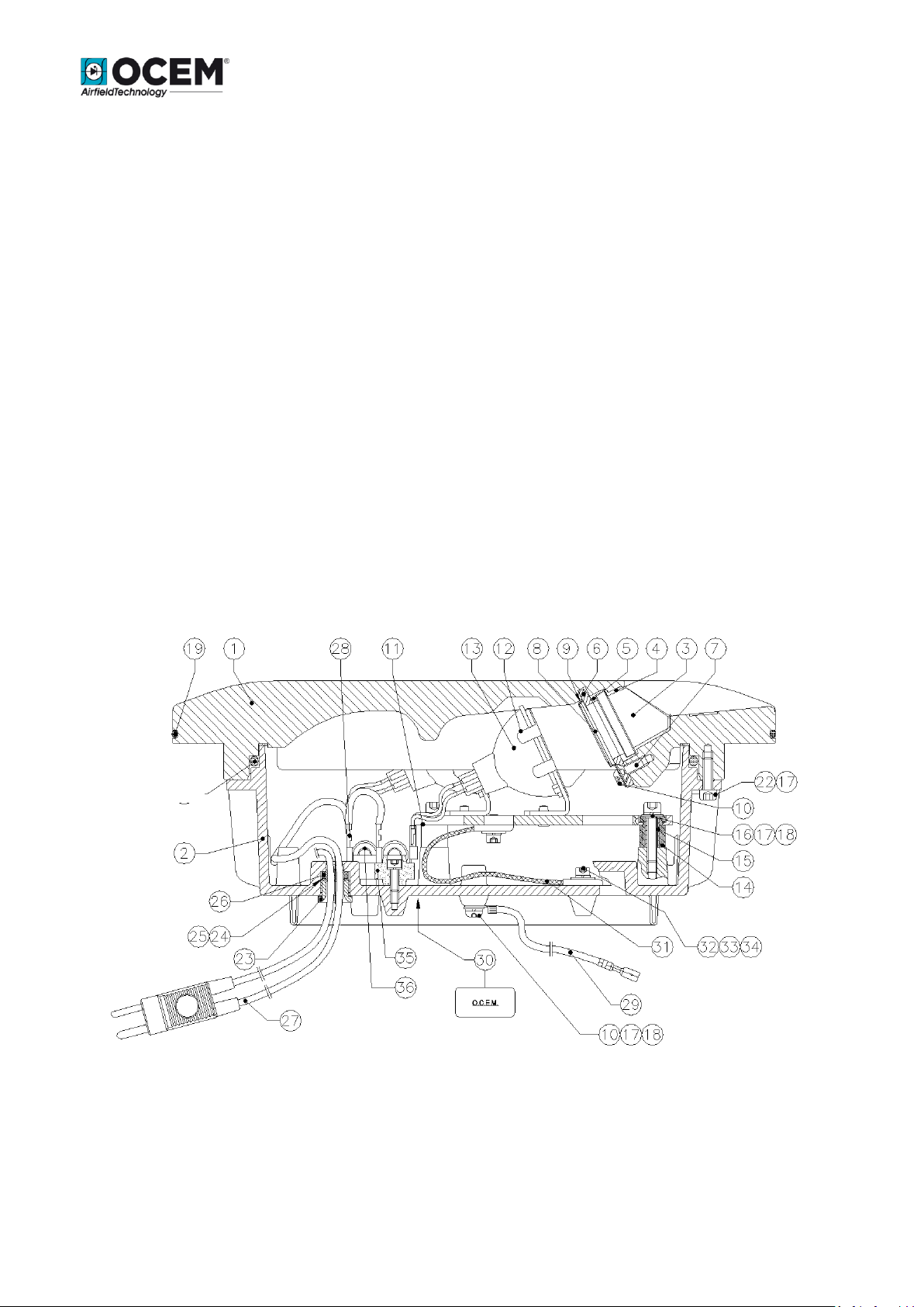
Figure 1 – Sectional View

Edition 11/03/2014 Supersedes edition 04/30/2012
INSET RUNWAY EDGE LIGHT SLRE
INSTRUCTION MANUAL FOR USE, INSTALLATION AND MAINTENANCE
Document UT-MT-0428 Page 11 of 35
No. Description Qty
1 Dome .................................................................................................................... 1
2 Lower cover.......................................................................................................... 1
3 Prism .................................................................................................................... 2
4 Prism gasket ......................................................................................................... 2
5 Teflon prism gasket .............................................................................................. 2
6 Mounting plate .................................................................................................... 2
7 HSFH M5x12 inox screw ...................................................................................... 6
8 Filter ..................................................................................................................... 2
9 Filter holder.......................................................................................................... 2
10 HSCH M5x10 inox screw ...................................................................................... 4
11 Lampholder .......................................................................................................... 1
12 Lamp elastic spring .............................................................................................. 2
13 Lamp ..................................................................................................................... 2
14 Vibration-damping block ..................................................................................... 4
15 Spacer................................................................................................................... 4
16 HSCH M5x16 inox screw ...................................................................................... 4
17 Ø5 inox grower washer ........................................................................................ 8
18 Ø5 inox grower washer ........................................................................................ 5
19 O-Ring 41150 silicone .......................................................................................... 1
20 O-Ring 6850 silicone ............................................................................................ 1
22 HSCH M5x16 inox screw ...................................................................................... 3
23 Cable gland - Nut ................................................................................................. 2
24 Cable gland - Washer ........................................................................................... 2
25 Cable gland – Washer (PTFE) ............................................................................... 2
26 Cable gland - Gasket ............................................................................................ 2
27 Cable lead with plug............................................................................................. 2
28 Cable lead with plug . Female faston terminal .................................................... 4
29 Grounding cable lead with male faston terminal ................................................ 1
30 Identification label ............................................................................................... 1
31 Bare copper plate ................................................................................................ 2
32 HSCH M4x10 inox screw ...................................................................................... 2
33 Ø4 inox grower washer ........................................................................................ 2
34 Ø4x12x1 inox washer ........................................................................................... 2
35 Insulating strip ..................................................................................................... 2
36 Fuse cutout .......................................................................................................... 2
Figure 2 – Part List
 Loading...