

Page 1
PROFESSIONAL MEASUREMENT TECHNOLOGY
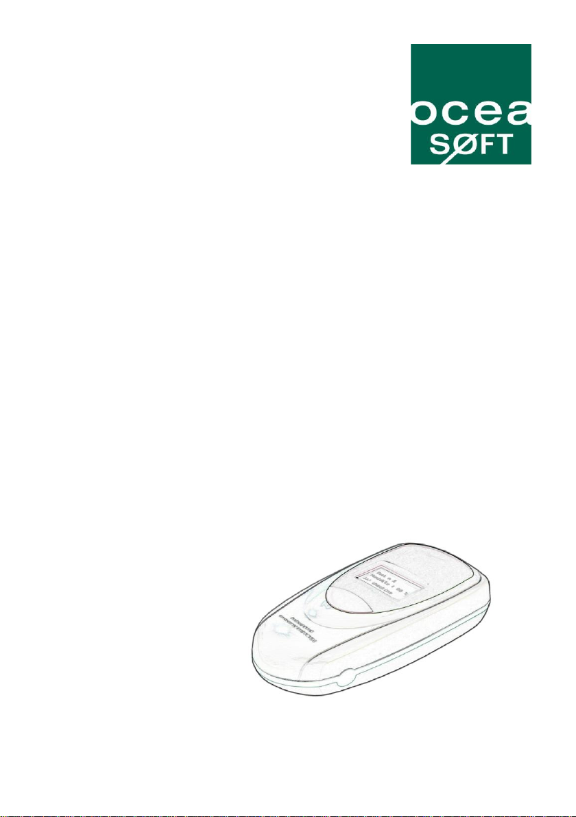
Cobalt® 2 Temperature
Monitor
(Internal and External Digital Probes)
Installation guide
www.oceasoft.com | support@oceasoft.com
Page 2

2 | Cobalt Temperature Monitor Installation
Page 3
Notices
Safety instructions
IMPORTANT NOTE: Do not use this product for protection or as part of automated
emergency system or as for any other application that involves protecting people
and/or property. Customers and users of Oceasoft products are responsible for
making sure that the product is fit for the intended usage. Do not open the product
casing and do not disassemble or modify internal components in any manner.
Oceasoft products do not contain any internal components that require user
intervention or repair. If the device shows signs of improper operation, disconnect it
immediately from its power source and contact Oceasoft technical services.
Battery warning
This product contains a lithium battery. Make sure you respect polarity
(+/-) when inserting batteries into OCEASOFT devices. Reversing
polarity by inserting the batteries incorrectly can cause the product to
heat up, and may lead to a battery liquid leak. Use only batteries
recommended by OCEASOFT. Do not change battery types, such as
or even different types of batteries of the same brand. Incorrect batteries may cause
the device to heat up, and may result in a fire or battery liquid leakage. Never dispose
of batteries in fire. Do not charge regular batteries that are not specifically
rechargeable. When batteries are low, or in case the battery-operated device in
question remains unused for a lengthy period of time, remove the batteries from the
device in order to avoid any risk of battery liquid leakage. Never leave batteries within
the reach of children. In case of a battery leak, avoid all contact with the liquid present
on the batteries. Rinse with clear water immediately in case the battery liquid comes
into contact with the eyes, mouth or skin. Contact a doctor or emergency service
immediately. Battery liquid is corrosive and can damage vision, or cause blindness or
chemical burns.
such as alkaline and magnesium, or use batteries of different brands,
FCC statement
This device complies with part 15 of the FCC rules. Operation is
subject to the following two conditions: (1) This device may not cause
harmful interference, and (2) this device must accept any interference
received, including interference that may cause undesired operation:
FCC Part 15 §107 - §109 - §207 - §247 (Ed 2008).
Conformity with European regulations
This product has been tested by Oceasoft S.A.. The “CE” mark on
this device indicates compliance under the Radio Equipment and
Telecommunications Terminal Equipment Directive 1999/5/EC. The
following standards were applied for the evaluation of compliance with
v2.1.2 (2007-06); Safety: EN 60950-1:2006/A11:2009
Notices | 3
this directive: EMC: EN 301 489-3 v1.4.1 (02); Radio: EN 300 222-2
Page 4
WEEE compliance
This wireless device complies with the essential requirements and other relevant
provisions of the Waste Electrical and Electronic Equipment Directive 2002/96/EC
(WEEE Directive).
Environmental protection
Please respect local regulations concerning disposal of packaging, unused wireless
devices and their accessories, and promote their recycling.
RoHS compliance
The wireless device is in compliance with the restriction of the use of certain
hazardous substances in electrical and electronic equipment Directive 2002/95/EC
(RoHS Directive).. Do not dispose of this product with household trash. Oceasoft
recycles this product under certain conditions. Please contact us for more information.
Disclaimer and limitation of liability
Oceasoft assumes no responsibility for any loss or claims by third parties which may
arise through the use of this product. This document is non-contractual and subject to
change without notice.
© 2010 Oceasoft, S.A.. All rights reserved. Oceasoft, the Oceasoft logo, Cobalt,
ThermoServer and ThermoClient are the exclusive property of Oceasoft. All other
brands mentioned are the property of their respective owners.
January, 2010 Ref: ING-ENR-100119-03-MMA
4 | Cobalt Temperature Monitor Installation
Page 5

Table of contents
Notices .............................................................................. 3
Table of contents ............................................................. 5
Introduction ...................................................................... 6
Pre-requisites ................................................................. 6
Package contents ........................................................... 6
Product overview ............................................................ 7
What is a Cobalt 2 temperature module?........................ 7
Installation procedure...................................................... 9
Before you begin ............................................................ 9
Placing external probe and Cobalt 2 module ................ 11
Activation and automatic wireless configuration............ 12
Software configuration .................................................. 13
Testing the connection ................................ ................. 13
Basic module configuration .......................................... 14
Additional configuration ................................................ 16
Appendix ................................ ................................ ........ 17
Troubleshooting ............................................................ 17
Specifications ............................................................... 18
Contact information ...................................................... 18
Table of contents | 5
Page 6

Introduction
Congratulations and thank you for choosing the Oceasoft Cobalt 2
wireless temperature monitor. This document covers Cobalt 2 modules
with either internal or external probes.
This Installation Guide describes how to get your new Cobalt 2 module
up and running. Detailed configuration instructions and software settings
are provided in the complete Cobalt 2 User Guide provided with your
product.
Pre-requisites
For the purposes of this Installation guide, we assume that:
ThermoClient/ThermoServer software is installed and
configured on your computer, and that you have appropriate
access rights to configure devices.
A Cobalt receiver is installed on your computer or network.
Please see the relevant product manuals for details on installing Cobalt
receivers and ThermoServer/ThermoClient software.
Package contents
Cobalt 2 wireless monitoring module with battery
Internal or external temperature probe
o Digital Temperature Internal Modules (+10° to +50°C)
Ambient temperature measurement
o Digital Temperature External Modules (-40° to +80°C)
Freezers, refrigerators, and cold rooms
o Digital Temperature External Modules (-40° to +120°C)
Ovens, incubators, and water baths
Cobalt mounting kit with plastic holder, magnet, screws and
Velcro®
For modules with external probe only:
o Flat cable (-40°C to +80°C)
o Sensor mounting kit with 2 wire-ties and 4 plastic
holders with adhesive backing
6 | Cobalt Temperature Monitor Installation
Page 7

LCD display with
temperature, signal
and battery indicators
Mounting holder
Push-button
Product overview
Configurable data logging, wireless transmission and alerts
Automatic wireless set-up
Temperature range: external probe -40°C to +80°C or -40°C to
+120 °C; internal probe 10°C to +50°C
Wireless range from 25-100 meters (65-325 ft) indoors up to
approximately 700 meters (2,300 ft) in line of sight
Operating temperature range for wireless module: 0°C to +50°C
Calibration certificate downloadable on-line directly from within
ThermoClient software.
What is a Cobalt 2 temperature module?
Cobalt 2 temperature modules read and record temperature values,
then transmit them wirelessly to a central database managed by
Oceasoft ThermoClient software. Alerts can be sent automatically in
case readings exceed configurable threshold values.
Figure 1 – Cobalt 2 wireless temperature module (shown here without
external probe)
Introduction | 7
Page 8

Each Cobalt 2 end-point module may only connect back
to one receiver as shown above. Any given module
cannot be read by multiple receivers.
Typical installation
Cobalt 2 modules transmit temperature readings and alerts to a PC
running Oceasoft ThermoServer/ThermoClient software, equipped with
a wireless receiver. The receiver may also be located remotely from the
PC on a network device server. Repeaters may be used when the
wireless range between the receiver and the Cobalt 2 end-point module
is too great. The diagram below shows these basic configurations:
Figure 2 – Typical Cobalt 2 wireless configurations
Cobalt 2 modules may be installed on the outside of refrigerators and
freezers, with the probe place inside the enclosure and connected via
the provided capillary cable. Modules with internal probes should not be
placed in cold-rooms.
8 | Cobalt Temperature Monitor Installation
Page 9

Installation procedure
The procedure described here assumes that ThermoServer/
ThermoClient software is installed on your computer, and that your
Oceasoft wireless receiver is configured and ready to use.
Before you begin
1. Connect the temperature probe firmly to one end of the capillary
cable by joining the connectors (without unscrewing them).
2. Connect the other end to the Cobalt 2 wireless module.
Placing your Cobalt 2 module for best performance
For optimal operation, follow these recommendations when physically
placing your device:
Do not place the module within 40 cm (16 inches) of another
module.
Make sure the wireless module is not placed on an electrical
conduit or cable tray (such as for computer network cables).
For best results, place the module so that it faces the general
direction of the receiver antenna. Modules without displays may
be placed on top of refrigerators or freezers.
Keep around 20 cm (8 inches) clear space around the module.
A module that is “stuck” between two refrigerators may not
communicate effectively.
Make sure all cables, if any, are firmly attached, that you can
open and close the enclosure door without forcing, and that the
capillary cable remains flush with the enclosure door joint.
See Appendix (pg 17) for additional considerations.
Placing the probe within the enclosure
Depending on your refrigerator or freezer model, it may be better to
leave the probe sitting on a shelf inside the enclosure rather than
sticking it to a side wall. This is particularly relevant in cases where you
have carried out a mapping study and determined the ideal location for
the probe. In that case, make sure that the probe does not interfere with
loading and unloading of your product(s) and that the location does not
represent a risk either for your product(s) or the probe.
Installation procedure | 9
Page 10

Recommended order for installing modules
In addition to placing your Cobalt 2 module as described above for best
wireless performance, you may also optimize overall network
performance by proceeding with installation as follows:
1. Examine the general layout of your site to determine the
placement of your Cobalt 2 modules. The extent of your preinstallation site survey depends on the number of modules to
install. Feel free to contact your sales representative for more
information on this topic.
2. Place all modules in their final locations before running wireless
setup (described below in Activation and automatic wireless
configuration, on pg. 12).
3. Begin activation by pressing on the module’s button for three
seconds (long-press), starting with the modules closest to your
receiver, working your way “out” in concentric circles. This
enables each Cobalt 2 module to establish the optimal
connection to your receiver.
Figure 3 – Start installation with modules closest to your
receiver and work your way “out” in concentric circles.
10 | Cobalt Temperature Monitor Installation
Page 11

Placing external probe and Cobalt 2 module
1. If you have a Cobalt 2 module with an external probe, run the
temperature probe into the enclosure via the door joint, taking
care to place the flat cable flush with the joint.
2. Clean the surface for the probe using alcohol to remove any
grease or dirt.
3. Attach one of the plastic cable holders to the probe, remove the
protective strip from the adhesive, and place the holder on the
clean spot inside the enclosure.
4. Place the probe/capillary cable connector on the inside the
enclosure in the same manner, as shown here:
Figure 4 – Probe inside refrigerator enclosure (modules with
external probe only )
5. Your mounting kit includes a plastic holder that can be mounted
using the provided magnet, screws or Velcro®. Choose the
method that is most appropriate for your situation and place the
Cobalt 2 module as described earlier in Placing your Cobalt 2
module for best performance (pg. 9), for example:
Figure 5 – Cobalt 2 mounted on refrigerator door
6. Attach or coil excess cable neatly.
Installation procedure | 11
Page 12

The module begins data-logging even if it does not
connect to the wireless system.
Activation and automatic wireless configuration
The Cobalt 2 temperature monitor is a standalone device that runs on
battery power. To activate your Cobalt 2 module and add it automatically
to your wireless monitoring network:
1. Insert the provided battery, if not already installed, making sure
to respect the polarity (see image printed inside battery slot).
2. To begin collecting temperature data right away and initiate the
wireless configuration sequence, press the button on the front
of the module for 3 seconds.
If a receiver or repeater is within wireless range, the Cobalt 2
module automatically establishes the wireless connection,
as shown in the sequence of screen shots below:
Figure 6 – Cobalt 2 module automatic wireless set-up sequence
12 | Cobalt Temperature Monitor Installation
Page 13

If this test does not show a wireless signal, please refer
to the Cobalt 2 User Guide for instructions on adding
modules into the system manually.
Software configuration
When activating your Cobalt 2 module as described above, the device
adds itself to your current ThermoServer/ThermoClient configuration.
Testing the connection
Check wireless signal strength
You may use ThermoClient to test the wireless signal strength as
described here, entering your login name and password when prompted
by the software.
1. Launch ThermoClient on your computer and enter your login
name and password to continue.
2. Select Settings Sensor settings, or press F11.
3. Click on Add/Update a module.
4. Select your receiver in the pick-list (“PC1” in Figure 7), then
select the wireless module from the sensor list on the left.
Figure 7 – Configuration with Cobalt 2 module on receiver
“PC1”
5. Click on Power to test the connection.
Software configuration | 13
Page 14

Basic module configuration
Cobalt 2 modules offer a variety of data-logging, alert and transmission
options. This section describes the basic settings to get started right
away. Please see the complete Cobalt 2 User Guide for more details.
Move the Cobalt 2 module into a group
1. Launch ThermoClient on your computer and enter your login
name and password to continue. The new Cobalt 2 should be
listed as shown here, where “PC1” refers to the receiver and
“SDP-PC1” refers to a generic group for new un-configured
modules connected to that receiver.
Figure 8 – New temperature sensor in generic “SDP” group
2. Press F11 or select Settings Sensor settings.
3. Drag the new sensor from the “SDP” group to your real group:
Figure 9 – Move sensor from generic “SDP” group to your real
group
14 | Cobalt Temperature Monitor Installation
Page 15

4. Click on Yes OK Close to update the module, save this
change, and return to the tree structure, as shown here:
Figure 10 – Temperature sensor in “Main floor” group
Test module by running an on-demand temperature read
You may confirm end-to-end operation by launching an on-demand read
from ThermoClient.
1. Click on the sensor in the tree structure (“Temp Sensor 1” in our
example).
2. Click on the current temperature (black zone in the image
below) to read the sensor wirelessly and update the display:
Figure 11 – Run an on-demand read to confirm end-to-end
communication
Software configuration | 15
Page 16

Additional configuration
Your Cobalt 2 module offers many features that are controlled by your
system’s ThermoServer/Thermo client software. Use the software to
define:
Measurement period
Frequency of data transmission
Threshold values for alerts
Alarm notification via phone, fax, e-mail and SMS
Probe calibration/correction parameters
Archiving
Many of these settings are accessed by pressing F11 or selecting
Settings Sensor settings, as shown here:
Figure 12 – Main sensor settings screen
Please see the Cobalt 2 User Manual for more details on these and
other important features. Click on Help to open the PDF file directly.
16 | Cobalt Temperature Monitor Installation
Page 17

Appendix
Troubleshooting
If you are having difficulties with your configuration, take a look at these
frequently-asked questions before contacting technical support. Most
common problems are actually quite simple to resolve. Here are some
frequently-asked questions:
There is nothing displayed on the Cobalt 2 module screen. What
should I do? First check to make sure the battery is installed and that it
is inserted in the right direction (+/- according to image in the battery
slot). Try testing or changing the battery. Contact technical support if the
battery is OK and still nothing is displayed on the screen.
I press the button for three seconds but my Cobalt 2 does not
connect to my receiver? Try bringing the module closer to your
receiver. If it works closer, then you may need to use a repeater in order
for the wireless signal to reach the Cobalt 2 module in its final location.
Also check to make sure the receiver is working properly.
Is it OK to have of 25% for my Cobalt 2 module?
No. The signal for each device must show a value higher than 30%
when you click on the Power button in ThermoClient. Higher values are
better.
The Cobalt 2 module shows a strong signal, but I still don’t get any
temperature readings. This is usually due to a loose cable or
improperly connected temperature probe. Check the capillary cable
between the Cobalt 2 module and the probe. Unplug the probe and plug
it back in. Make sure there are no exposed wires. Try a different probe.
Can the probe be submerged in glycol? Yes. In order to “absorb”
sudden variations in temperature, such as those caused by opening and
closing the enclosure door, you may submerge the metal part of the
probe in glycol or glycerol. This limits inconsequential temperature
variations recorded by the probe. Check your laboratory’s Quality guide
for recommendations and make sure to use a volume of glycol that
corresponds to the volume of product(s) that you are monitoring. To
achieve the same results, you may also delay the transmission of
alarms via software and leave the probes exposed.
Appendix | 17
Page 18

Specifications
ISM (Industrial Scientific Medical) band with 3 frequencies:
US/CAN 915 MHz; Europe 868 MHz; APAC 434 MHz; India
and other countries 467 MHz
Channel width: 50 kHz
Frequency deflection: 16 KHz
Transmission speed: 9600 Baud in NRZ mode
Modulation type: GFSK
Driven receiver sensitivity for BER= 1%: -107dbm to -110 dBm
Driven transmission: 8 dBm to 10 dBm
Power output: 25 mW
Plastic enclosure: ABS with IP65 protection
Operating conditions: 0°C to 50°C (32° to 122°F); 0 to 90% RH,
non- condensing
Size: 132.7 x 64.2 x 34 mm (5.2 x 2.5 x 1.3 in.)
Weight: 150 g (5.3 oz.)
Contact information
By e-mail
If you need help with your Oceasoft product, please send a detailed email to us at this address: support@oceasoft.com
Be sure to include as many details as possible, including specific
product references, software versions, screen shots from your
computer, etc.
By phone
Oceasoft has a dedicated line for technical support, open Mon-Fri, 9:00
am – 1:00 pm and 2:00 pm – 6:00 pm (CET).
Tel: +33 499 13 67 33
18 | Cobalt Temperature Monitor Installation
Page 19

www.oceasoft.com | support@oceasoft.com
Appendix | 19
 Loading...