

Shenzhen Oceanus Medical Device Co.,Ltd.
Shenzhen Oceanus Medical device Co., Ltd
Address: No.2,East side,Floor 2,Yinjin Building, Liuxian Road 3,Xin'an Zone 71,Xin'an
Subdistrict,Baoan District,Shenzhen,China
Wellkang Ltd.
Address:Suite B, 29 Harley Street LONDON W1G 9QR, England, United Kingdom
Tel: +353(1)4433560 Fax: +353(1)6864856
O-Wave-I
Operating manual
OCE-ESWT-002
[After-sales service] :Shenzhen Oceanus Medical device Co., Ltd
[Address] : No.2,East side,Floor 2,Yinjin Building, Liuxian Road 3,Xin'an Zone 71 , Xin'an
Subdistrict,Baoan District,Shenzhen,China
[Tel]:+86-755-86599459 [Fax]:+86-755-86599450
The first release data of this manual: 2018-01-01 Versions: A/6

Operating manual
- 1 -
1 Product brief introduction
No.
Part name
No.
Part name
1
Host
9
Air intake and fan
2
Energy knob
10
Foot switch
3
Handwriting pen
11
Power switch
4
Display screen
12
Fuse wire
5
Frequency knob
13
Power port
6
SD card slot
14
Handle port
7
Therapeutic handle (therapeutic head)
15
Foot switch port
8
Air outlet
16
Product nameplate
15
16
The O-Wave I is a medical device produced by Shenzhen Oceanus Medical Device Co., Ltd, its
main utilizes the energy generated by the solenoid drive actuate bullet body inside therapeutic
handle, so that the impact of the bullet body to pulse colliding the therapeutic head, the acoustic
pulse will be converted to the exact ballistic shock wave, have a good therapeutic effect for
musculoskeletal disorder and other. It brings the hope to the life of skeletal muscle disease patients,
please read the manual carefully when using the product.
2 Product intended use
The O-wave I used in the area of adjuvant therapy of chronic joint pain and muscular pain and be
used by medical staff
3 Primary structure of the product
The product mainly consists of host, therapeutic handle and foot switch, which hosts including
upper and lower case, power supply, main board and touch screen. Accessories include power line,
handwriting pen, handle bottom case, keys and aluminium alloy suitcase. Supplies accessories
include silicone cap and therapeutic handle/therapeutic handle and foot switch belongs to
exchange component. The product structure chat is as follows:

Operating manual
- 2 -
4 Product main features
a) The human engineering design provides setting and operates conveniently;
b) 7 inches color crystal Chinese and English touch screen design, intuitive and clear;
c) Import power source, to ensure instant shock output effect;
d) Energy and frequency selection, conform to treatment demand;
e) Single or dual output is optional, and provides a various professional probe;
f) There are 7 adjustable preset reference solutions;
g) Adopt a portable design.
1)Working power supply: 100-240VAC,frequency: 50/60Hz
2)Environmental requirements
Item
Temperature requirement
Humidity requirement
Atmospheric pressure
Work environment
requirement
20℃-32℃
25%-75%RH
700hPa-1060hPa
Storage/ Transport
environment requirement
0℃-40℃
10%-93%RH
700hPa-1060hPa
5.2 Product main technical parametric description
●Pulse energy levels:
60–185 mJ (at the applicator),freely adjustable in 10 mJ increments
at 22 Hz max. 90 mJ
at 16 Hz max. 120 mJ
at 10 Hz max. 185 mJ;The output tolerance is ±40mJ, The CV is ±5%
●Working frequency
1~22 Hz,adjustable in 1 Hz increments
●Work pattern
4 continuous capture modes(shots /4/8/12 pulses)
●Reference operating version
7 preset operation versions, can be adjustable
●Suggestion for treatment parts
Exceeds 25 preset treatment suggestion
The main product features of O-Wave I as follow:
5 Product requirements and main parametric description
5.1 Product requirements
●Control function
All function implemented by touching operation; rotary knob controls energy and frequency;
multi-directional foot switch coordinates with therapeutic handle operation.
●Product boundary dimension

Operating manual
- 3 -
290×240×130mm(length/width/height)
●Product weight
2.07kg (do not contain therapeutic handle and foot switch)
●The description of therapeutic handle/therapeutic head to shock wave
The therapeutic handle design conforms to human engineering, combines anodized aluminium
shell with fan cooling, produces electromagnetic force drive projectile working by means of coil
electrical over. The boundary dimension is 23cm, diameter is 5cm (the maximum); the minimum
service life of therapeutic handle is 2,000,000 times (the calculation according to a number of
strokes); only need to do some daily maintenance and nursing for appearance, it is recommended
to use cleaning with medicinal alcohol; the therapeutic head divided into 3 specifications:
6/15/25mm (diameter); the minimum service life of each therapeutic head is 150,000 times (the
calculation according to a number of strokes).
●Power consumption
100/240VAC 50/60 Hz,300VA
●The fuse (wire fuse) specification
250V/10A
●The requirement of therapeutic head temperature
The external temperature of therapeutic head of the O-wave I is not greater than 48℃.
●Electrical safety classification
Type BF applied parts
6 Application method of product
6.1 The information needs to understand before the use of product
Remarks:
●1-Settings button: click on this icon, the display screen will jump to the settings interface
●2-Beginning button: click on this icon, the display screen will jump to treatment/scheme
1
2
1)Graphical interfaces introductions
1.1)Beginning interface

Operating manual
- 4 -
interface
1.2)Settings interface
1.2.1)General settings interface
General settings view:
●Single-end
Remarks:
1
2
3
4
8
4
3
2
1
13
14
5
6
10
12
111
9
●1-“Confirm” button: click on this icon, the display screen will jump to the beginning interface.
●2-“Versions” button: click on this icon, the screen will pop up a version dialog box; you can see
the product software information in this dialog box.
●3-“Standard” button: click on this icon, the general settings will return the default.
●4-“Touch calibration” button: click on this icon, the display screen will pop up a prompt box,
indicating whether you need to calibrate the touch screen.
●5-Handle state bar: if the connection state is not normal, and the state bar turns blue, it means
that the handle is not found.
●6-“Test handle” button: click on this icon, the handle will work once. It is use for testing the
handle whether is normal work.
●7-Foot switch state bar: it displays the working state to foot switch. If treading the foot switch,
the state bar will turn blue and it means the working performance is normal.
●8-Luminance increased button: click on this icon, the luminance of display screen will increase,
and the value of the 12thitem on the interface will corresponding increase.
●9-Luminance decreased button: click on this icon, the luminance of display screen will decrease,
and the value of the 12thitem on the interface will corresponding decrease.
●10-Voice shutdown button: click on this icon, the voice will shut down.
●11-Voice booting button: click on this icon, the voice will boot.
●12-Luminance item: the value of luminance represents the luminance of display screen.
●13-Booting screen of pull-down menu: click on this menu value of this button, select which
Operating manual
- 5 -
opening mode, the retrospective interface will automatic jump to the corresponding working
1— Language pull-down menu: click on this button, this menu will choose your needed language.
Remarks:
4
1
2
3
5
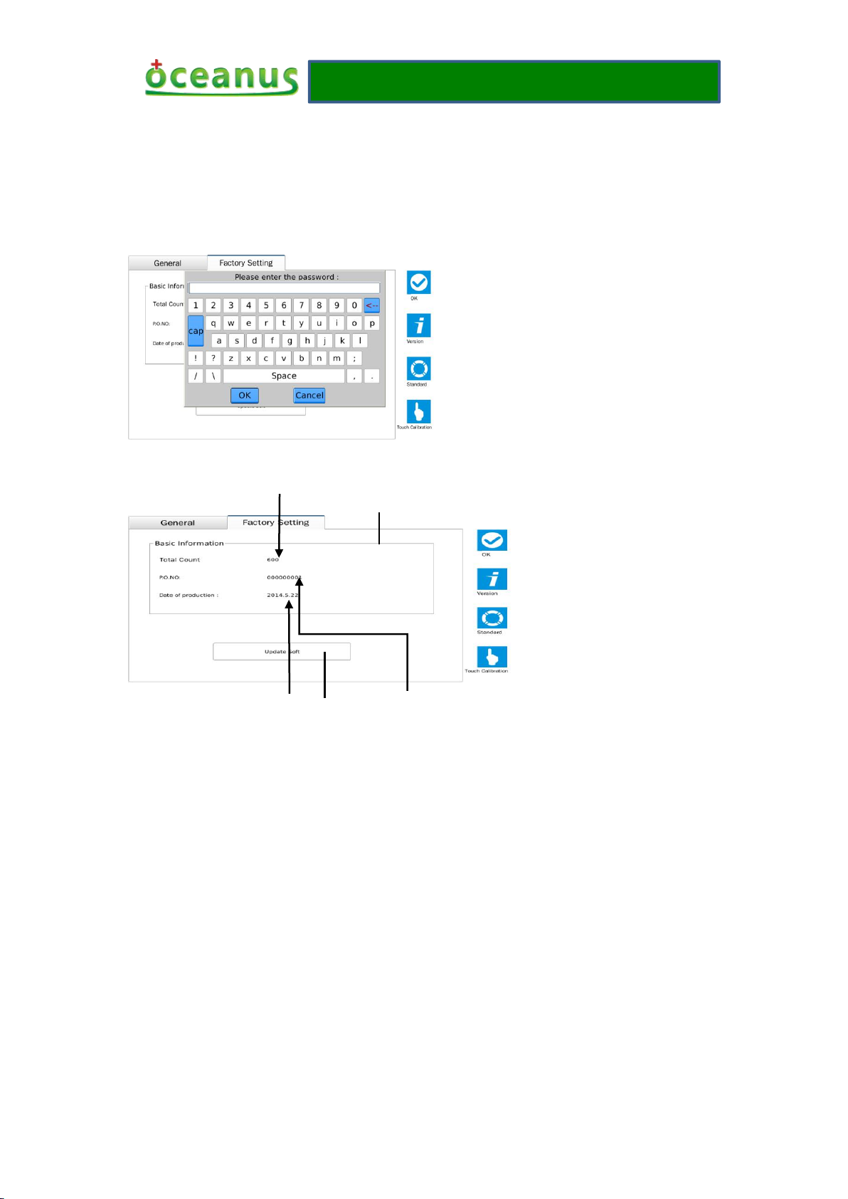
●1-Basic information box: it displays some key information of this product. If you click on this
box, it will pop up the following password dialog box: the operation authorization of this dialog
box belongs to manufacturer owned, is use for monitoring the product and be closed to visitors.
●2-“Update software” button, is use for updating software, usually by the manufacturer to use.
●3-Counter, summarizing the working grand total data of the product.
●4-SN number, the product SN brings into correspondence with machine SN.
●5-Date of manufacture
3)Treatment interface
interface.
1.3)Factory settings
Factory settings view

Operating manual
- 6 -
13
12
11
10
9
8
7
6
5
4
3
2
1
18
17
16
14
15
Remarks:
●1-“Scheme” button: click on this icon, the display screen will jump to the scheme interface.
●2-“Therapy” button: click on this icon, the display screen will jump to the treatment interface.
●3-“RAM” button: click on this icon, the display screen will jump to the RAM interface.
●4-“Return” button: click on this icon, the display screen will jump to the working interface.
●5-“Homepage” button: click on this icon, the display screen will jump to the beginning interface.
●6-Frequency display bar: adjust the knob on the shell; the frequency of display value will
change.
●7-“Save” button: click on this icon, it will pop up a dialog box to save the current treatment data.
●8-“Count direction” button: click on this icon, the count value will become display value of the
maximum or minimum.
●9-Count direction
●10-“Reset” button: click on this icon, when the count direction displays upward, the value is 0;
when displays down of setting value.
●11-Handle working state bar
●12-Energy display bar: adjust knob on the shell can display current energy value.
●13-Energy display bar: adjust knob on the shell can display with energy to change the graphics.
●14-Treatment scheme title: with the change in treatment programs to change themselves.
●15-Current count value: it records the current number of strokes of handle. If the number of
strokes equal to the setting value, the handle will stop work, and the current count value will
flash all the time.
●16-Setting value: the maximum value is 10,000 times number of strokes, such as display “-” and
it represents the current setting value is 10,000 times.

Operating manual
- 7 -
●17-Settings treatment data box: click on this box, it will pop up a dialog box to set the treatment
data.
●18- Working mode button: click on this box, it will pop up a dialog box to choose a working
mode.
3)Scheme interface
5
4
3
2
1
7
6
Remarks:
●1-“Scheme” button: click on this button, the display screen will jump to the scheme interface,
after entering the scheme interface, this button will automatically become grey and it cannot
operate for the moment. You can enter the next level menu to operate. The following 2/3 items are
same as it.
●2-“Therapy” button: click on this button, the display screen will jump to the treatment interface.
●3-“RAM” button: click on this button, the display screen will jump to the RAM interface.
●4-“Return” button: click on this button, the display screen will jump to the working interface.
●5-“Homepage” button: click on this button, the display screen will jump to the beginning
interface.
●6-“Treatment” button: click on this button, the display screen will jump to the treatment interface;
setting value, frequency, mode these parameters will also be transfer to the working interface.
●7-Treatment scheme selected menu: as the reference choose of treatment scheme, you can select
by yourself according to different schemes.
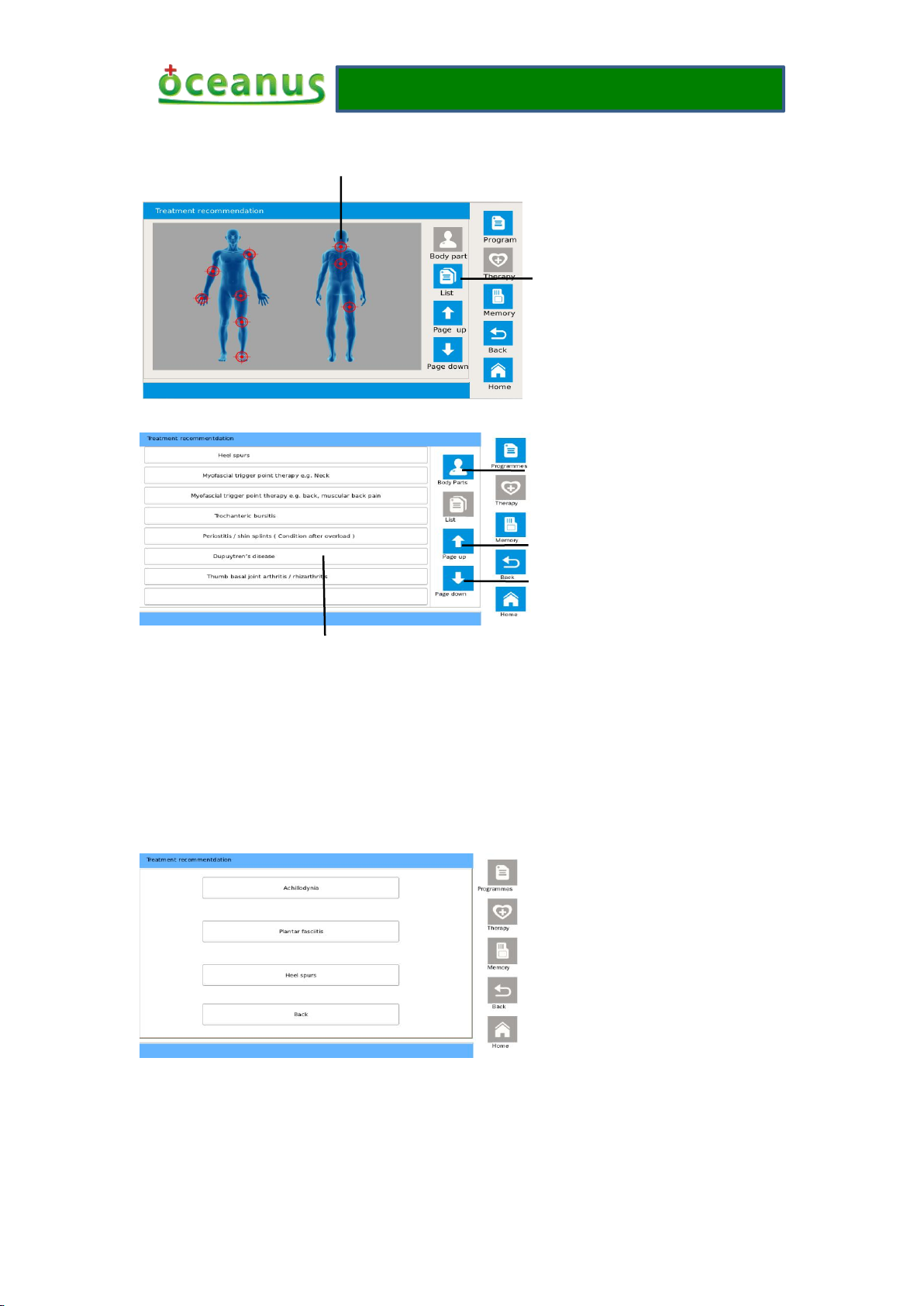
4)Therapy interface
Body parts view:
Operating manual
- 8 -
List view:
3
4
6
●1-“List” button: if press this button, the treatment part will display in form of the list.
●2-One of treatment part: if press this button, the display screen will jump to an interface, this
interface will display the detailed description of this treatment part. In additional, a part may be
several diseases, the screen will pop up the following dialog box that what kind of disease let you
choose, the picture as shown:
2
1
Remarks:
Click on other buttons expect “Return”, the display screen will jump to an interface, and this
interface will display the detailed description of this treatment part. If press the “Return” button
that the dialog box will be cancelled.
●3-Body parts button: if press this button, the body treatment part will display by means of the
picture.

Operating manual
- 9 -
●4-“Previous page” button: if press this button, it will turn to the content of the front page in the
list.
●5-“Next page” button: if press this button, it will turn to the content of the rear page in the list.
●6-Body parts of disease button: if press the button, the display screen will jump to an interface,
this interface will display the detailed description of this treatment part.
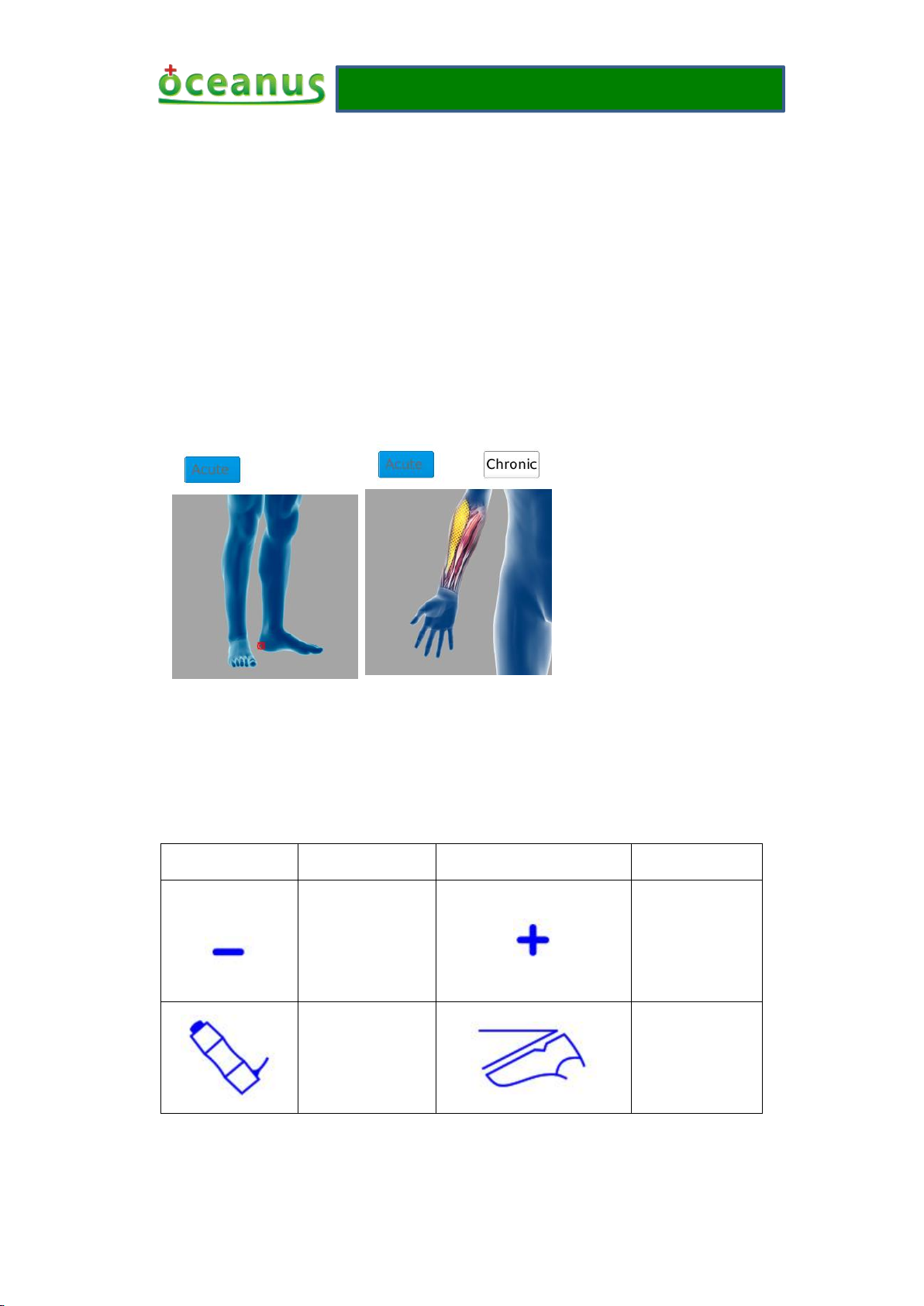
5)Treatment described interface
Remarks:
●1-“Treatment” button: if press this button, the display will jump to the treatment interface;
frequency, energy, setting value these will also be transfer to the working interface.
●2-“Cancel” button: if press this button, this dialog box will be cancelled.
●3-“Acute disease” button: if you are a patient with acute disease, you can click on this button;
this interface will give an only treatment suggestion for you. If the button is blue that represents
the button has been selected and cannot click again.
●4-“Chronic disease” button: if you are a patient with chronic disease, you can click on this button;
this interface will give an only treatment suggestion for you. If the button is blue that represents
the button has been selected and cannot click again.
4
3
1
5
2
1
2
3
4
6)RAM interface
Remarks:
●1-“Delete” button: if press this button, it will delete the selected item.

Operating manual
- 10 -
●2-“Treatment button”: if press this button, the display screen will jump to the treatment interface,
1)Booting
After plugging in the power wire, foot switch and therapeutic handle, the power switch to the
“ON” position, the device is booting, about 17 seconds into the beginning interface.
2) Shutdown
Dial the power switch to the "off" position, the device off, automatic shutdown, but the power
wire must pull out after the device is completely shut down.
3) Normal work
The detection before normal work
Click on the Settings icon into the general settings interface, check the sound and luminance bar,
is the sound in the open mode, is the display luminance suitable for operator, and it can be
adjusted.
1 Handle connection examination
The handle status bar is mainly used to displaying the connection state of handle, normal display
is white, handle is not found shown in blue, and please check handle plug connection
2 Foot switch and handle test
the data saved by yourselves will be selected and that will be read and transmitted to the working
interface, including energy, setting value, mode and frequency.
●3-“Previous page” button: if press this button, it will turn to the content of the front page in the
list.
●4-“Next page” button: if press this button, it will turn to the content of the rear page in the list.
●5-Option item: the data saved by yourselves in the selected one.
6.2 Product specific operating method

Operating manual
- 11 -
Click on the handle test button, frame color will become dark, if the handle will work once (heard
snapped), said the handle with a normal working condition, otherwise the handle will not work.
Depress the foot switch, foot switch test bar becomes blue, indicating that the foot switch is
operating normally, such as discoloration need to check the connection plug connection is good.
3 Into the treatment interface
Click on the "Confirm" button to return to the beginning interface, then click on the "Boot" button
to enter treatment interface, if not treatment interface, you can click on the "Return" button to
enter treatment interface.
4 Start work
If the energy value is 0, you need to adjust the energy knob on the left side of the shell to change
its value, while clicking count dialog box to set the number of treatment which you want and save
it. As shown below:
Then attaching the therapeutic head of handle to the site in need of treatment, foot switch is
depressed to begin treatment, as follows:
5 User-defined choice
Before starting work, you can also change the settings value, frequency and mode to choose your
favorite way for treatment. For detailed operation, please refer to the 6.1 treatment interface
description.
4) Interface switching

Operating manual
- 12 -
There are 3 situations about the jump between interfaces:
1 Jump directly between interfaces
Under this situation, you need to click on the button associated with the interface. For example: in
the treatment of screen, click the "program" button, you can jump directly to the scheme interface.
2 Jump from the beginning interface to the intended interface.
You can set the value of booting screen interface as the intended interface in the settings interface.
For example, set the value of the booting screen is "RAM"; click on the "Start" button will jump to
the RAM interface. Of course, do not do the above settings, click on the "Start" button, if you did
not enter a intended interface can also jump to a intended interface according to situation ①.
3 Fixed direction Jump
The settings interface jump to the other interfaces can only be through the "Confirm" button to the
booting screen, and then do the next jump. Treatment description interface via the "Cancel" button
to jump to the therapy interface, through the "treatment" button to jump to the treatment interface.
5)Save and read data
Only in the working interface, you can save the data. Click on the "Save" button in the working
interface, the screen will pop up a dialog box in this dialog box, you must enter a name for the
data you want to save, and then click on the "Save" and you will complete the preservation of data.
Jump to the RAM interface, you can see the names of all the data you saved, select one you want
to read out, click on the "treatment" button, the display screen will jump to the treatment interface,
the energy, settings value, frequency, and mode will be transmitted to the treatment interface, now
you can use them to work.
6)The use of scheme
In the scheme interface, select one you want, then clicking on the "treatment" button, the display
screen will jump to the treatment interface. In the treatment interface, if the energy value is 0, you
must adjust the housing knob to change its value, and then depressing the foot switch.
7) View the treatment recommendations and use for treatment
First, jump to the treatment interface, you can click the button in the list view or click on parts of
the body inside view. In addition, if a site may have several diseases, the screen will pop up a
dialog box that allows you to go by clicking on the button above to select one of them. After
clicking, you will see on this site for a detailed description of the treatment of selected diseases.
Finally, you can click on the "treatment" button to jump to the working interface, frequency, power,
mode and setting values of these parameters will be passed to the working interface.
Now, you can depress the foot switch, and use them to go to work.
6.3 Product precautions for use

Operating manual
- 13 -
6.3.1 Error message
●Error temperature
The temperature alarm appears that the current handle temperature exceeds the settings parameter
of software, must be stopped until cooling fan stops running, and then starting up. The description
of appeared position:
The picture is at the bottom of the treatment interface (handle work status bar).
●Handle is not found
The occurrence of handle is not found, the alarm represents that the device cannot scan the handle,
pull out the handle and re-insert the handle and check whether you can easily pull out it, if they
cannot pull out and the alarm signal to eliminate said the handle has a good connection. Appeared
position has a same wrong with “error temperature”.
●SD card is not found
The occurrence of SD card is not found the alarm represents that the SD card cannot insert or
damaged, if the card had been in the slot but still has this problem, you can reboot the device to
solve, you cannot find the SD card after rebooting, it may mean this card is damaged, it is
recommended to replace another one to continue to use. The description of appeared position:
The picture appears in the factory setting of settings interface, only occur when upgrading
software.
●The new software cannot be found
This alarm indicates that the software is not downloaded to the SD card or incorrect download way.
Re-download the new software to the SD card images directory can solve this problem. Appeared
position is the same as "NO SD-card found".
●The service life of handle is expired
This alarm indicates that the current life of the handle has expired, you can replace the new handle,
to avoid because of the handle using a maturity not been promptly replaced, the proposed operator
checked regularly in use, inspection methods: Click the Settings button --- select factory mode ---
Check the total value can be. Appeared position is the same as "temperature error".
6.3.2 Operating interface icon introductions

Operating manual
- 14 -
Icon
Introduction
Icon
Introduction
Icon
Introduction
Icon
Introduction
Version
information
Back to the
previous level
Love treatment
recommendation
s
Downward
Save
Back to the
booting interface
Treatment list
Settings
Standard or
default
Increase
Delete
Body parts
Click and touch
by hand
Decrease
Confirm
Up and down
direction
RAM
management
Start up
Cancel
Selected work
head 1
Scheme detailed
description
Treatment
Upward
Selected word
head 2
6.3.3 Sing information explanation
●Working interface of count
There are 3 situations in the working interface of count value; the following three pictures
represent three cases:
f
g
h
In the case of f, the set value is 100, and the current count is 10, which means the current count
before reaching 100, the handle can also be hit 90 times.
In the case of g, the set value displays "-" and indicates a value of 10,000, the current count
displays 100, the handle can be worked until 9,900 of the current count is displayed.
In the case of h, the set value displays 100, and the current count displays 100, then the value of
the count value will always blink. At this point the handle will not work, said that it has completed
the designated. Release the foot switch, reset the data, or is cleared and then set the data.
Operating manual
- 15 -
●Count direction on the working interface
If the value of the count direction is displayed as "up", the current count value will increase from
zero to the set value. When it reaches the set value, the current count will flash, and the handle
does not work.
If the value of the count direction is displayed as "down", the current count value from the set
value will start decreasing until it is 0, when is 0, the current count will flash, and the handle does
not work.
●Treatment description interface of button colors
There are 3 colors on the treatment description interface of button colors: blue, grey and white.
For example is the following view.
As shown in this interface icon of background is blue, has defaulted as the treatment mode by the
software. If this interface icon of background is grey that represents this function cannot use at the
same time. If this interface icon of background is white that represents this function can switch
work from blue background icon.
●silk-screen shell
Silk-screen
Explanation
Silk-screen
Explanation
Minus
identification of
frequency/energy
adjusting knob on
the O-wave I
Plus
identification of
frequency/energy
adjusting knob
on the O-wave I
The Therapeutic
headle port label
of O-wave I
Foot switch
identification of
foot switch on
the O-wave I

Operating manual
- 16 -
7 Product installation and trouble removal
7.1 Product installation
Please check the power outlet should have a good grounding wire before installing, and this
machine is strictly prohibited without ground power to use. The machine requires away from
water installation.
The instrument has its own embedded software, and the software has been installed at the factory.
Machine installation does not require professionals to delegate user at installation.
7.2 Common trouble removal
1) Fault phenomenon: it is unable to boot.
Solution:
Check whether the power wire has been properly connected, the interface is loose.
Check the power switch whether is already appropriated for "open" position.
Check whether the fuse has burned out, and replace the same specification as burned fuse.
If the cause of the above checks still cannot boot, please replace the power wire of the same
interface.
Tip: After power on the device, you can see the logo information on the display screen at least 5~7
seconds.
2) Fault phenomenon: touch inaccurate
Solution:
Click on the "Touch Calibration" button on the Settings interface, and in once to recalibrate the
touch screen.
3) Fault phenomenon: the therapeutic handle does not work
3.1 )If in the treatment interface, the therapeutic handle does not work after treading the foot
switch, the solution is:
●The therapeutic handle is not connected, or not even close.
You can see the blue state bar will show “not found the therapeutic handle” at the bottom of
working interface, check the connector to therapeutic handle whether connect well, after
unplugging reinstall expressed readiness has been connected properly. If the handle is still not
found or the therapeutic handle is problem, need to replace the handle.
●Temperature
If the handle temperature is too high, the handle will not work. Blue status bar at the bottom of the
working interface will show "temperature error", because the handle temperature exceeds the set
temperature, it can be continue to use until the fan operation stops on its own. Otherwise, the

Operating manual
- 17 -
temperature is not the cause of the problem.
●The energy on the working interface
In the working interface, if the energy is shown as "0", the handle cannot work. You must adjust
the knob on the housing to change its value, and then depress the foot switch. If the handle can
work, and the energy that is causing this problem, otherwise it is not.
●The current count value on the working interface
In the working interface, if the current count keeps flashing, the handle also does not work. You
can click the "Reset" button or change the setting value to solve this problem. Otherwise, it is not
the cause of the problem.
●Mode on the working interface
If you choose the other one mode expect the “continuous” mode, the handle can only hit four
times or 8 or 12 times after treading the foot switch. If you want to continue to handle the work,
you must release the foot switch and foot switch is treaded again. Otherwise, it is not the reason.
●Other reasons
If the described above you have been checked on and without any problems, please skip to the
settings interface and tread the foot switch to see the color of its information display bar whether
turns blue, if there is no discoloration, need to replace the foot switch.
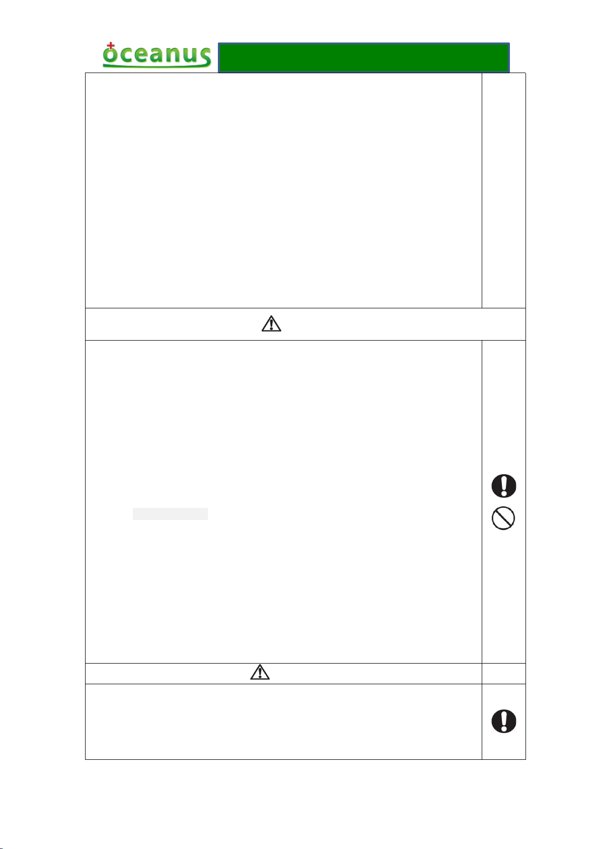
8 Safety precautions
■The manual said that the purpose of warning sign and legend is safe and proper using the product
Warning sigh
Meaning
using
contraindication
It shows that it will appear the dangerous of casualties or serious injury in the error
use.
warning
It shows that it will appear the possibility of casualties or serious injury in the
error use.
attention
It shows that it will appear the possibility of personal injury or damaged goods in
the error use.
Warning
① The therapeutic apparatus cannot be used with the HF apparatus to avoid burns or damaged
apparatus
② If the patient himself uses the therapeutic apparatus and HF apparatus at the same time, the
part of massage plate may be cause burns on apparatus, it may also damage the apparatus; If
by yours, and prevents the harm to you and others.
■The warning sign and legend as well as their meaning is as follows:
Operating manual
- 18 -
use the apparatus near (1 meter) the short wave or microwave therapeutic apparatus, the output
of apparatus may be instability.
③ It will increase a danger of heart fibrillation by using electrode close to the chest.
④ Do not modify this equipment without authorization of the manufacturer
⑤ Serious twist injury within 24 hours, prohibiting the use of treatment of shock wave.
⑥The product will produce certain heat when used(when in the process of ultimate working,
The safe working temperature has built-in 68℃, and the therapeutic head’s temperature will
Reach to 68℃),please always pay attention to monitor patient's condition.
⑦ All accessories and replaceable parts of the products (silicone cap, therapeutic
head/therapeutic handle and foot switch) are not belong to interchangeable part, any change
you must contact manufacturer to purchase.
⑧ When operating this product, the operators use therapeutic handle to treat patients but
they must be medical staff and need to wear nosocomial medical gloves.
Contraindication
●General factors:
1) Serious heart attack, arrhythmia and high blood pressure;
2) The patient with a cardiac pacemaker;
3) Not curative hemorrhagic disease of coagulation disorders of patient;
4) The use of immunosuppressants;
5) All kinds of cancer patients;
6) Patient with thrombosis;
7) Pregnant woman.
8) Growing children
●Local factors:
1) The patient with local infection and skin burst;
2) Tendon and fascia of acute injury;
3) The patient with synovial fluid leakage;
4) The therapeutic parts in the brain/lung and spinal cord organizer;
5) Atrophy and infectious nonunions;
6) Massive defective bone nonunions.
Precautions
1) Before treatment, you should tell patients the feeling during treatment, eliminating the
patients’ concerns and obtaining cooperation.
2) Before treatment, ask and check the skin of therapeutic parts has or not the hypaesthesia,

Operating manual
- 19 -
large scar or damaged.
3) Treatment should be removing metal items of therapeutic parts, such as wrist watch,
hairpin, jewelry, etc.
4) Please turn off the power when not in use.
5) The product cannot be used in any location for treatment head.
6) It is not allowed to use the therapeutic head direct contact with the skin treat in the
treatment.
7) The product will produce certain noise and heat during use, please pay attention to the
surroundings whether fitness for use.
8) For security reasons, the energy and frequency of the device will not reach the maximum
at the same time.
9) The product will produce feeble electromagnetic field during use, please keep away from
strong magnetic environment.
10) There is a long term effect on the device and therapeutic handle, the handle for a
long-term use can cause ballistic wear, may wear out ballistic and cause internal short
circuit. The device components for a long-term use will be aging phenomenon.
11) The device cannot squeeze, may cause display screen broken when drop; the device does
not receive any data input in the working state, can avoid artificial misoperation harm to
patients in the work.
12) When connecting the device, the connector of work handle and the connector of foot
switch are different (one is 2PIN, one/two are 10PIN), there will be no fault phenomena;
the plug has hooks structure, not loose to slide.
13) Please use the matching handwriting pen when device operation on the touch screen, click
on the touch screen are not allowed to use other sharp object.
14) When device is abnormal, if they cannot handle by themselves, please contact our
after-sales service; it is not allowed to take apart shell privately or flash other software,
the resulting damage will be borne by the customers themselves.
9 Product maintenance and nursing
●Energy conservation
Operating manual
- 20 -
After treatment, please shutdown the power, save the energy and protect the device.
●Cleaning
With a clean cloth and 75% alcohol to clean the host shell, the interior does not require cleaning. It
requires that with a paper or cloth to clean surface coupling agent after completed at the same time.
Please use 75% medicinal alcohol to clean the surface of treatment caps before pre-treatment
again.
●Consumables
All accessories and replaceable parts of the product are not belong to general parts, if need to
replace, you must contact the manufacturer to buy.
●Coupling agent
In the treatment, use the coupling agent and special medical coupling agent of ultrasonic
transducer.
●Calibration
The basic operation of the product is by means of touch screen, it may cause touching off normal
because of a long term operation, and the recalibrate can by means of touching calibration
function of settings interface, then can continue to use.
●Service life
The minimum service life of the complete machine is 2,000,000 times (calculation according to
the number of strokes)
The minimum service life of each therapeutic head is 150,000 times (calculation according to the
number of strokes)
●Scrap processing
After confirming the product has been scrapped, the product cannot be thrown away and by the
hospital or nursing institutions unified scrap processing.
10 EMC declarations
1、This product needs special precautions regarding EMC and needs to be installed and put into
service according to the EMC information provided, and this unit can be affected by portable and
mobile RF communications equipment.
2、* Do not use a mobile phone or other devices that emit electromagnetic fields, near the unit.
This may result in incorrect operation of the unit.
3、Caution: This unit has been thoroughly tested and inspected to assure proper performance and
operation!
Operating manual
- 21 -
4、* Caution: this machine should not be used adjacent to or stacked with other equipment and
that if adjacent or stacked use is necessary, this machine should be observed to verify normal
operation in the configuration in which it will be used.
Warning The use of ACCESSORIES, transducers and cables other than those specified,
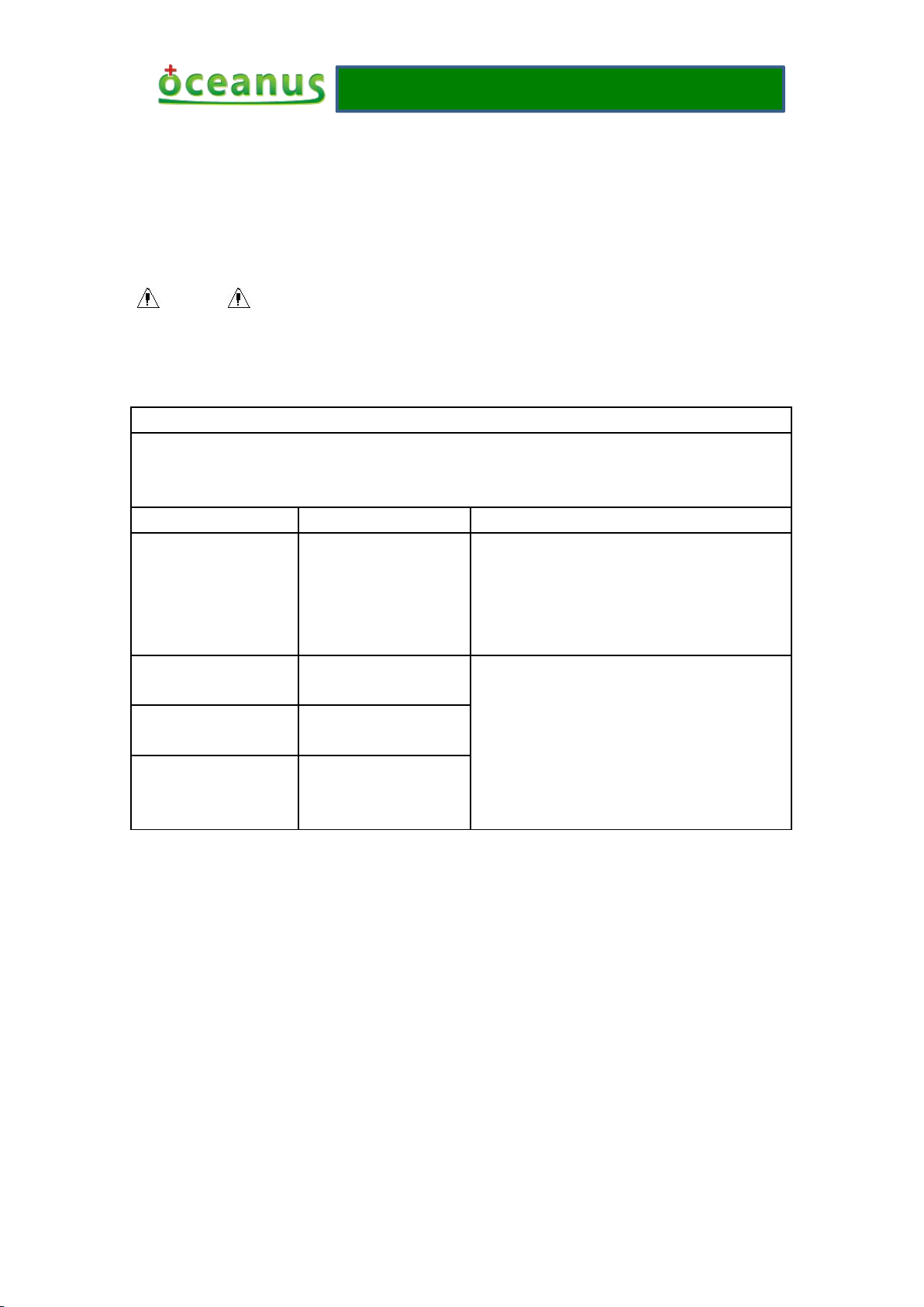
Guidance and manufacture’s declaration – electromagnetic emission
The OCE-ESWT-002 O-wave I is intended for use in the electromagnetic environment specified
below. The customer of the user of the OCE-ESWT-002 O-wave I should assure that it is used in
such an environment.
Emission test
Compliance
Electromagnetic environment – guidance
RF emissions
EN 55011
Group 1
The OCE-ESWT-002 O-wave I use RF energy
only for its internal function. Therefore, its RF
emissions are very low and are not likely to
cause any interference in nearby electronic
equipment.
RF emission
EN 55011
Class A
The OCE-ESWT-002 O-wave I is suitable for
use in all establishments, including domestic
establishments and those directly connected to
the public low-voltage power supply network
that supplies buildings used for domestic
purposes.
Harmonic emissions
EN 61000-3-2
Class A
Voltage fluctuations/
flicker emissions
EN 61000-3-3
Complies
with the exception of transducers and cables sold by the MANUFACTURER of the
AMBULATORY O-wave I as replacement parts for internal components, may result in increased
EMISSIONS or decreased IMMUNITY of the O-wave I.

Operating manual
- 22 -
Guidance and manufacture’s declaration – electromagnetic immunity
The OCE-ESWT-002 O-wave I is intended for use in the electromagnetic environment specified below. The customer or the
user of OCE-ESWT-002 O-wave I should assure that it is used in such an environment.
Immunity test
IEC 60601 test level
Compliance level
Electromagnetic environment -
guidance
Electrostatic discharge
(ESD)
EN 61000-4-2
±6 kV contact
±8 kV air
±6 kV contact
±8 kV air
Floors should be wood, concrete
or ceramic tile. If floor are
covered with synthetic material,
the relative humidity should be at
least 30%.
Electrical fast
transient/burst
EN 61000-4-4
±2 kV for power supply
lines
±1kV for input/output
lines
±2kV for power supply
lines
±1kV for input/output
lines
Mains power quality should be
that of a typical commercial or
hospital environment.
Surge
EN 61000-4-5
± 1kV differential mode
± 2kV common mode
± 1kV differential mode
± 2kV common mode
Mains power quality should be
that of a typical commercial or
hospital environment.
Voltage dips, short
interruptions and
voltage variations on
power supply input
lines
EN 61000-4-11
<5% U
T
(>95% dip in UT)
for 0.5 cycle
40% U
T
(60% dip in UT)
for 5 cycles
70% U
T
(30% dip in UT)
for 25 cycles
<5% U
T
(>95% dip in UT)
for 5 sec
<5% U
T
(>95% dip in UT)
for 0.5 cycle
40% U
T
(60% dip in UT)
for 5 cycles
70% U
T
(30% dip in UT)
for 25 cycles
5% U
T
(>95% dip in UT)
for 5 sec
Mains power quality should be
that of a typical commercial or
hospital environment. If the user
of theOCE-ESWT-002 O-wave I
requires continued operation
during power mains interruptions,
it is recommended that the
OCE-ESWT-002 O-wave I
be
powered from an uninterruptible
power supply or a battery.
Power frequency
(50/60Hz)
magnetic field
EN 61000-4-8
3A/m
3A/m
Power frequency magnetic fields
should be at levels characteristic
of a typical location in a typical
commercial or hospital
environment.
NOTE UTis the a.c. mains voltage prior to application of the test level.
Operating manual
- 23 -
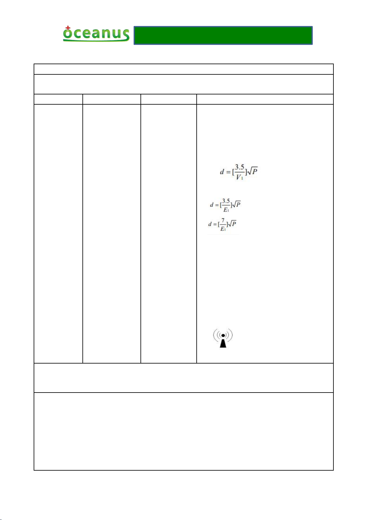
Guidance and manufacture’s declaration – electromagnetic immunity
The OCE-ESWT-002 O-wave I is intended for use in the electromagnetic environment specified below. The customer or the
user of OCE-ESWT-002 O-wave I should assure that it is used in such an environment.
Immunity test
EN 60601 test level
Compliance level
Electromagnetic environment - guidance
Conducted RF
EN 61000-4-6
3 V
rms
150 kHz to 80 MHz
3 V
Portableand mobile RF communications equipment
should be used no closer to any part of the
OCE-ESWT-002 O-wave I , including cables, than
the recommended separation distance calculated from the
equation applicable to the frequency of the transmitter.
Recommended separation distance
Radiated RF
EN 61000-4-3
3 V/m
80 MHz to 2.5 GHz
3 V/m
80 MHz to 800 MHz
800 MHz to 2.5 GHz
Where P is the maximum output power rating of the
transmitter in watts (W) according to the transmitter
manufacturer and d is the recommended separation
distance in metres (m).
b
Field strengths from fixed RF transmitters, as determined
by an electromagnetic site survey,ashould be less than the
compliance level in each frequency range.
b
Interference may occur in the vicinity of equipment
marked with the following symbol:
NOTE 1 At 80 MHz and 800 MHz, the higher frequency range applies.
NOTE 1 These guidelines may not apply in all situations. Electromagnetic propagation is affected by absorption and reflection
from structures, objects and people.
a
Field strengths from fixed transmitters, such as base stations for radio (cellular/cordless) telephones and land mobile radios,
amateur radio, AM and FM radio broadcast and TV broadcast cannot be predicted theoretically with accuracy. To assess the
electromagnetic environment due to fixed RF transmitters, an electromagnetic site survey should be considered. If the
measured field strength in the location in which the OCE-ESWT-002 O-wave I is used exceeds the applicable RF
compliance level above, the OCE-ESWT-002 O-wave I should be observed to verify normal operation. If abnormal
performance is observed, additional measures may be necessary, such as reorienting or relocating the OCE-ESWT-002
O-wave I
b
Over the frequency range 150 kHz to 80 MHz, field strengths should be less than 3 V/m.
Operating manual
- 24 -
Recommended separation distances between
portable and mobile RF communications equipment and the OCE-ESWT-002 O-wave I.
The OCE-ESWT-002 O-wave I is intended for use in an electromagnetic environment in which radiated RF disturbances are
controlled. The customer or the user of the OCE-ESWT-002 O-wave I can help prevent electromagnetic interference by
maintaining a minimum distance between portable and mobile RF communications equipment (transmitters) and the
OCE-ESWT-002 O-wave I as recommended below, according to the maximum output power of the communications
equipment.
Rated maximum
output power of
transmitter
W
Separation distance according to frequency of transmitter
m
150 KHz to 80 MHz
80 MHz to 800 MHz
800 MHz to 2.5 GHz
0.01
0.12
0.12
0.23
0.1
0.38
0.38
0.73
1
1.2
1.2
2.3
10
3.8
3.8
7.3
1001212
23
For transmitters rated at a maximum output power not listed above, the recommended separation distance d in metres (m) can be
estimated using the equation applicable to the frequency of the transmitter, where P is the maximum output power rating of the
transmitter in watts (W) according to the transmitter manufacturer.
NOTE 1 At 80 MHz and 800 MHz, the separation distance for the higher frequency range applies.
NOTE 2 These guidelines may not apply in all situations. Electromagnetic propagation is affected by absorption and reflection
from structures, objects and people.

Operating manual
- 25 -
11 The paraphrase of graphic symbol
12 Executive standards
EN 60601-1 : 2006/A1:2013 Medical electrical equipment — Part 1: General requirements for
basic safety and essential performance
EN 60601-1-2:2007 /AC:2010 Medical electrical equipment — Part 1-2: General requirements
for safety — Collateral standard: Electrom-agnetic compatibility — Requirements and tests
Label
Explanation
Label
Explanation
Serial number
This symbol is used to direct the use
r to refer to documentation for additi
onal information regarding the syste
m use or description.
The name and address of the
manufacturer
Keep dry
Date of manufacture
CE identification + noticed code
Contact its local authorities to dete
rmine the proper method of dispos
al of potentially bio hazardous part
s and accessories.
Anti-electromagnetic radiation
Type BF anti-shake
The name and address of the EU
representative
Fragile
The product conforms to the following standards and laws:

Operating manual
- 26 -
13 Accessories and parts
No.
Object
Material code
Quantity
Picture
01
Host
OCE-ESWT-002-01
1
02
Therapeutic
handle
OCE001010101Z
1
03
Foot switch
OCE001020102Z
1
04
Therapeutic
head
OCE001010101Z-07
OCE001010101Z-08
OCE001010101Z-09
Diameter of 6/15/25mm each 1
05
Power line
OCE00102040401
1
06
Handle
pedestal
OCE001010101Z-04
1
07
Handwriting
pen
OCE00101010405
1
08
Silicone cap
OCE001010101Z-06
10
09
Aluminium
alloy suitcase
OCE00103040101
1
10
Product
manual
OCE00103040402
1
Omit
14 Guarantee card

Operating manual
- 27 -
Warranty card
1. First of all thank you for choose our products, for more convenient for you, please carefully
2. The card is the warranty certificate, the user for safe keeping, if lost, will not be returned.
3. This product is only entitled to one year free warranty to the host, within a year, if the host go
4. The host failure caused by man-made accidents, misuse, abuse or irresistible natural factors,
5. Before the host maintenance, please back up your data yourself, the Company has no
6. Unauthorized change and disassemble, the company is not under warranty.
7. Other issues shall be negotiated between the parties to resolve, the final interpretation of the
Customer name: Contact number:
Address:
Product name: Product model:
Date of purchase: year month day
Warranty regulations:
read the regulations.
wrong, the product can be sent to the manufacturer will repair free of charge rely on this card,
other parts can contact the manufacturer to purchase a replacement.
the Company does not assume warranty obligations.
obligation for you to back up your data; if cause data loss in the process of maintenance, the
company does not undertake any responsibility.
Company.
Signed by the manufacturer:
Name: Shenzhen Oceanus Medical Device Co., Ltd Contact number: +86.755.8659-9459
Aftermarket address: No.2,East side,Floor 2,Yinjin Building, Liuxian Road 3,Xin'an Zone 71 ,
Xin'an Subdistrict,Baoan District,Shenzhen,China
For more information about the product or accessories, please consult the manufacturer, or please
visit the website: http://www.oceanuswave.com
 Loading...