

Ocean TV Ocean O37M, Ocean O45M Installation And User Manual
Ocean TV Ocean Series Antennas
OCEAN TV 1 www.oceantv.com.au
OCEAN TV
Satellite Antennas
www.oceantv.com.au
Ocean Series O37M and O45M
Installation and User Manual
Version 1.34
© Ocean TV 2010
Ocean TV Ocean Series Antennas
OCEAN TV 2 www.oceantv.com.au
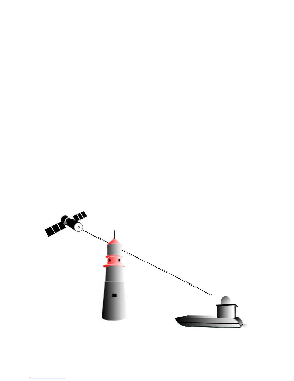
Blocked !
Figure 1-2 Satellite Blockage
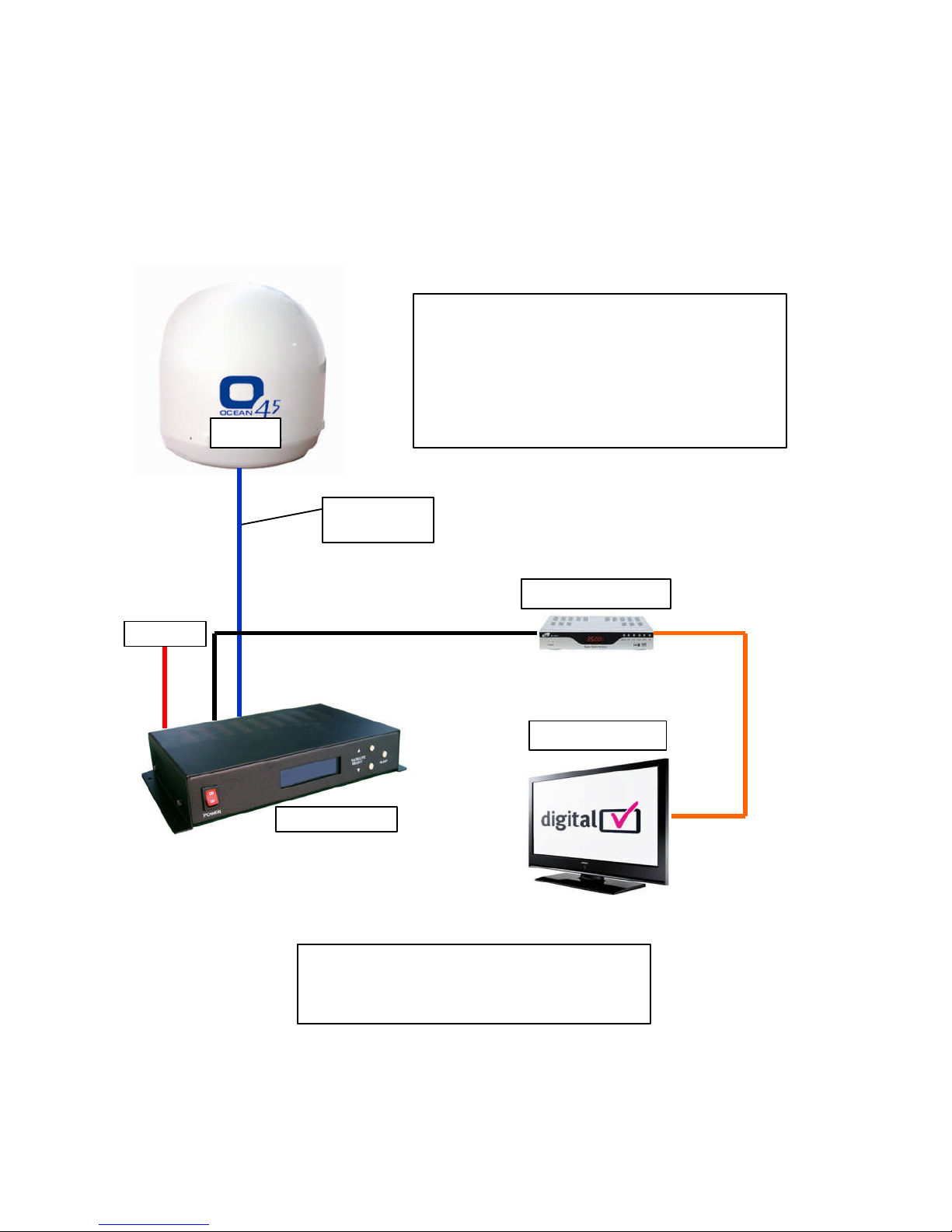
Antenna System Overview
A complete satellite TV system, illustrated in Figure 1-1, includes the O45M antenna connected
to a IDU, a satellite TV receiver, and a television set.
Direct Broadcast Satellite Overview
Direct Broadcast Service (DBS) satellites broadcast audio, video and data information from satellites located 22,000 miles in space. A receivingstation, such as the O45M antenna, should include a dish and satellite receiver to receive the signals and process them for use by the consumer audio and video equipment. The system requires a clear view of the satellite to maximize
the signal reception.
Objects such as tall lighthouse, bridges and big ship that block this view will cause a loss of signal. The signal will be quickly restored once the antenna has a clear line of sight again. Heavy
rain, cloud, snow or ice may also interfere with the signal reception quality. If the satellite signal
is lost due to blockage or severe weather condition, services from the receiver will be lost
(picture will freeze frame and may disappear). When the satellite signal strength is again high
enough, then the receiver will resume providingdesired programming services.
Ocean TV Ocean Series Antennas
OCEAN TV 3 www.oceantv.com.au
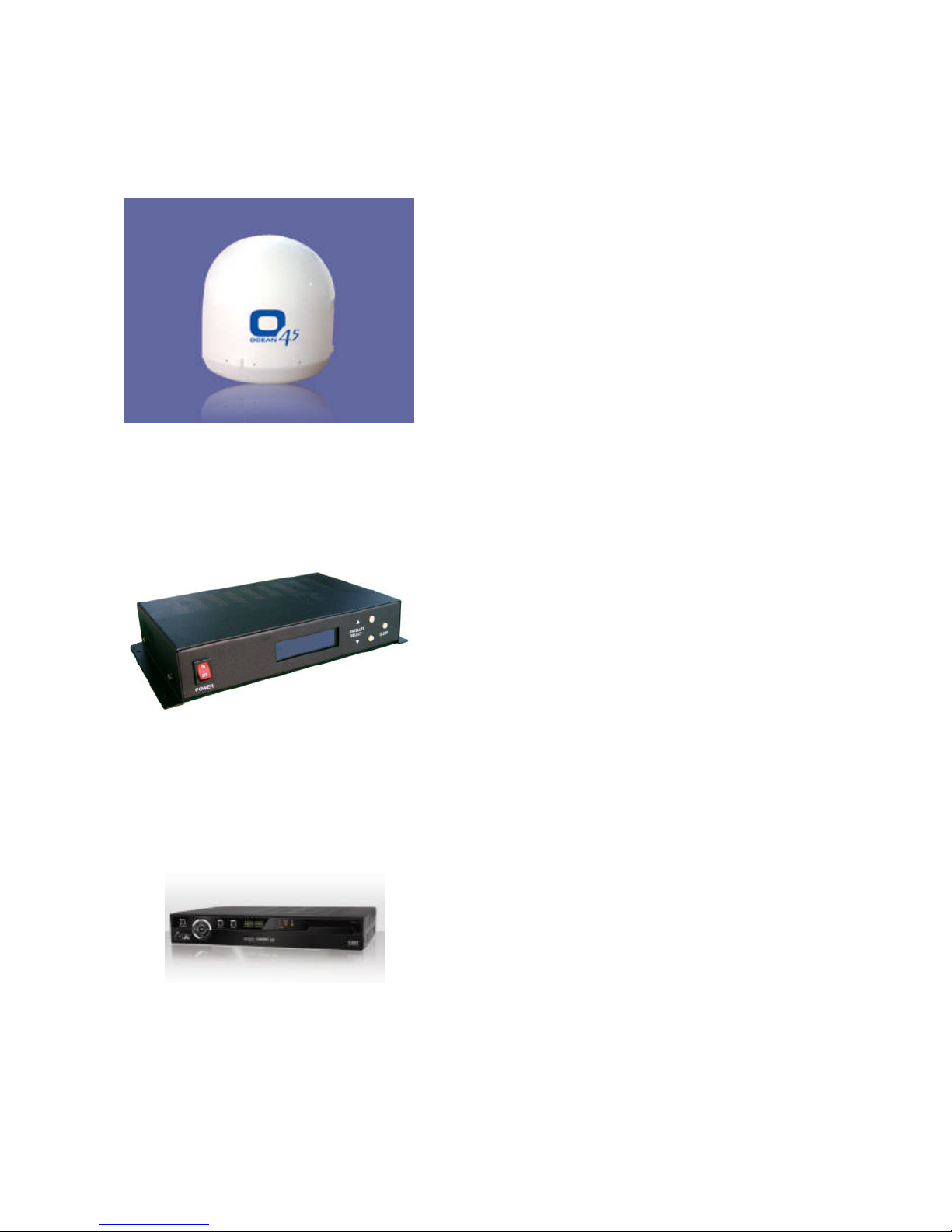
System Components
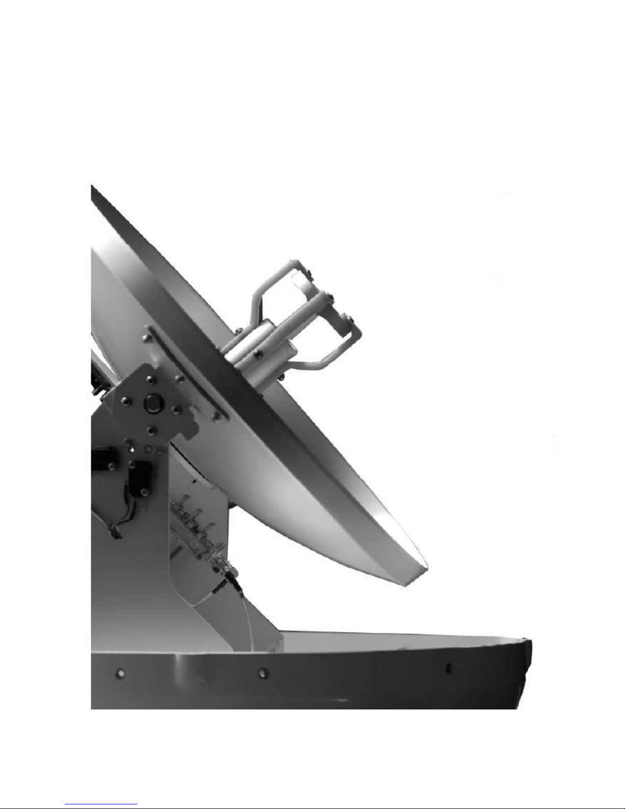
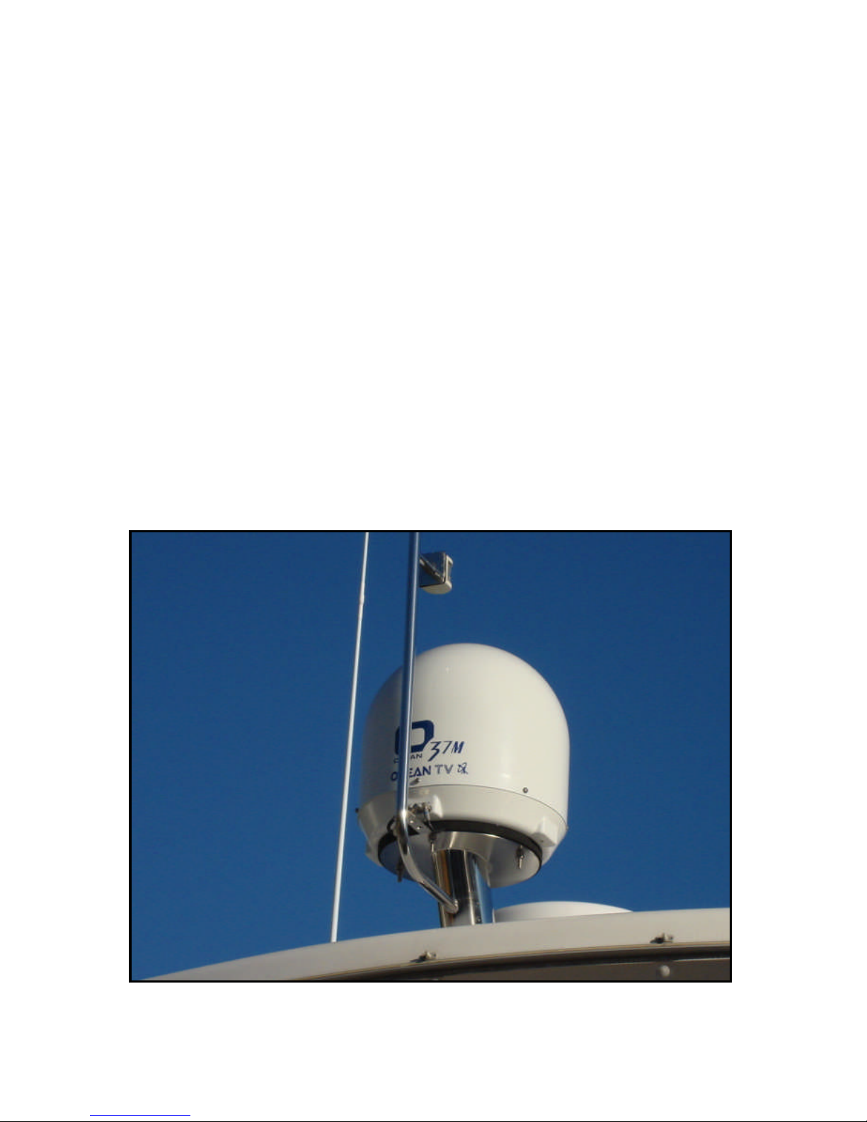
Antenna Unit
The antenna unit houses the antenna positioning
mechanism, LNB (low noise block), and control elements within a n enclosed weatherproof dome.
Weather tight connectors join the power, signal, and
control cabling from the below decks units.
IDU (InDoor Unit)
The IDU is the system’s user interface, providing
access to the system and its functions through an
LCD and three buttons.
The IDU also serves as the vessel’s junction box,
allowing the system to use vessel power, and supply
and receive data to/from the antenna unit.
Satellite Receiver
The Satellite Receiver is a Set Top Box that allows
the Satellite Signals to be displayed on the
Television.
Satellite Receivers are supplied by the end user or
under contract by a Subscription Satellite TV
Provider.
Figure 1 – 3 Sys tem Components
Ocean TV Ocean Series Antennas
OCEAN TV 4 www.oceantv.com.au
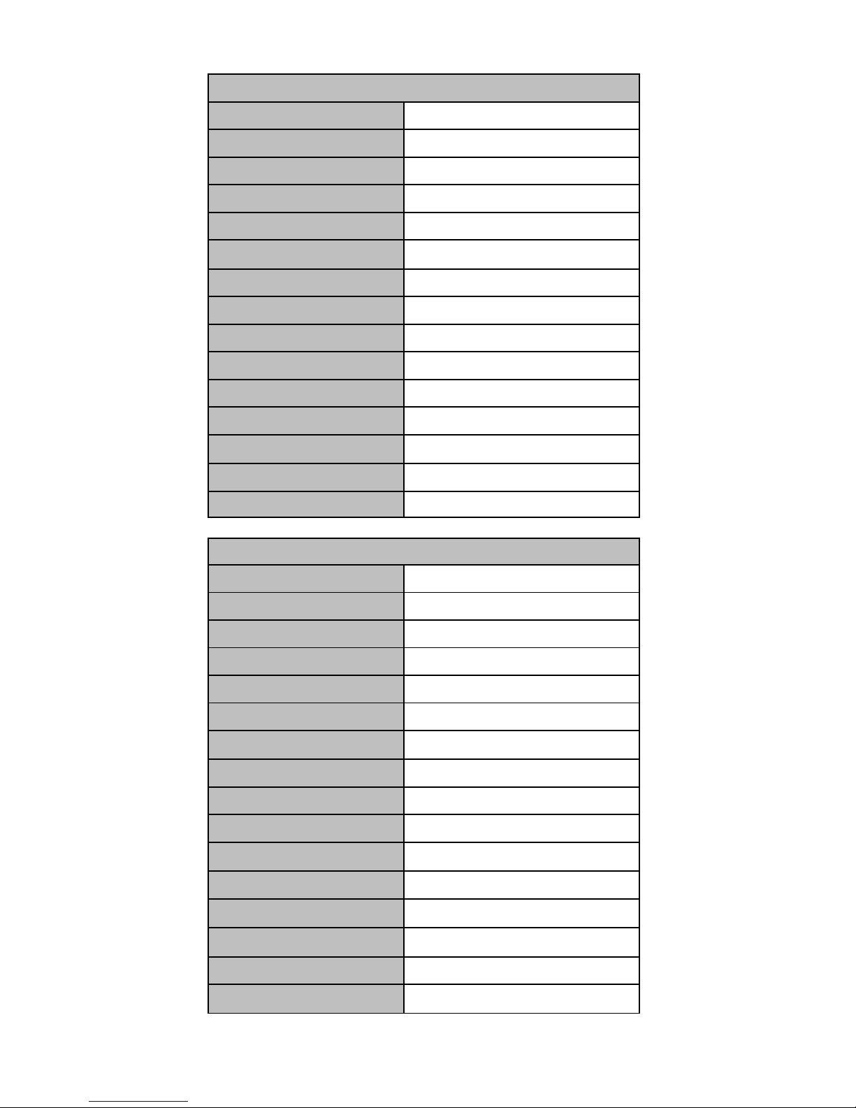
Antenna Type Parabola
Frequency Band Ku Band
OperatingFrequency 10.7GHz to 12.75GHz
Dish Dimension 450mm
RadomeDimension 550x580mm
Antenna Weight 15kg
Antenna Gain 33dBi
MinimumEIRP 49-48dBW
Polarization V/H or RHCP/LHCP
Type of Stabilization 2-Axis Step Motor
Elevation Range
5° to 90°
Azimuth Range
400°
TrackingRate
50°/sec
Temperate Range
-20° to 70°
Power 12~24VDC (24w at 12vdc)
Auto Skew Range
-90° to 90°
Ocean O45M
Antenna Type Parabola
Frequency Band Ku Band
OperatingFrequency 10.7GHz to 12.75GHz
Dish Dimension 370mm
RadomeDimension 440x430mm
Antenna Weight 9kg
Antenna Gain 31dBi
MinimumEIRP 50dBW
Polarization V/H or RHCP/LHCP
Type of Stabilization 2-Axis Step Motor
Elevation Range
5° to 90°
Azimuth Range
400°
TrackingRate
50°/sec
Temperate Range
-20° to 70°
Power 12~24VDC (19w at 12vdc)
Ocean O37M
Ocean TV Ocean Series Antennas
OCEAN TV 5 www.oceantv.com.au
SD SatelliteReceiver
Ocean TV System Overview
Setup 1
1 Television with SD Satellite Receiver
Antenna
12-24v DC
IDU Indoor Unit
Televisions
Coaxial Control
Cable
NOTE:.
Further Installation Options are available in Appendix E
Antenna System Overview
Figure 1 –1 System Diagram

Ocean TV Ocean Series Antennas
OCEAN TV 6 www.oceantv.com.au
1 Introduction
Specification………………….………………………………………………………………. 4
Antenna System Overview……………………………………………………………….. 5
Direct Broadcast Satellite Overview………………………….………………………. 6
Sy stem Components……………………………………………………………………..… 7
2 Installation
Unpacking the Unit………………………………..……………………...................... 9
Preparing for the installation…………………………………………………………. 10
Selecting the location………….………………………………………………….……… 11
Equipment and cable installation…………..…………………………………….…. 12
Setting the LNB Skew Angle (Manual Skew version only)…………………. 13
3 Operation
Receiving Satellite TV Signals…………….………………………………………….. 15
Turning the System On/Off…………..………………..……………………………... 16
Changing Channels………………………….…………………...…..……………….…. 17
Watching TV…………………………………………………………..…………….…..…. 17
Switching between Satellites……………………………………………….…………. 17
Operating th e IDU……………………………………….……………………………….. 18
Choosing the Correct Satellite to Track……………………...……………….... 19
4 Troubleshooting
Simple Check……………………………………………..………………….……………. 21
Causes and Rem edies……………………………….……..……………………...……. 22
i Appendix A
How to set the skew angle………………………………………………….....……. 23
ii Appendix B
Satellite Cov erage Map…………………..…………………………..………..……. 26
iii Appendix C
Firmware Upgrade…………………….……………………………………..…………. 27
iv Appendix D
O37M Antenna Drawing..…………………….…..………...…………………..…. 31
O45M Antenna Drawing..…………………….…..……………………………....….32
v Appendix E
Sy stem Diagram s..…………………….…..………...……………………..……..…. 33
vi Appendix F
Satellite Coverage Maps……………….…..………...…………………….……..…. 40
5 Accessories
Installation and User Accessories…………………………………………………. 42
Contents

Ocean TV Ocean Series Antennas
OCEAN TV 7 www.oceantv.com.au
Notes, Cautions, and Warnings
Caution - Improper handling by unqualified personnel can cause serious
damage t o this equipment. Unqualified personnel who tamper with this
equipment may be held liable for any resultant damage to the equipment.
Install un der DRY condition ONLY. Do not install this system in the rain, or
under w et conditions. Moisture may effect the electronics and v oid warranty.
Warning - Two people are needed to install the antennas onto the roof. Do
not try to install the antenna by y ourself.
Note - Beforey ou begin, carefully read each of the procedures in this manual. If y ou have not perform ed similar operations on similar equipment, do
not attempt to perform these procedures.
Welcome
Congratulations on purchasingthe Ocean TV Marine Satellite Antenna System.
The Ocean Series O37M and O45M satellite antenna system is a innovative and technologically
advanced satellite In-Motion system. The O37M/O45M has a unique combination of state-of-the
art components with the most sophisticated satellite acquisition and tracking programs to provide
the followingfeatures:
■ Fast satellite acquisition
■ Gyro and Signal Stabilised smooth tracking
■ Compatible with any Satellite Receiver
■ Compatible with all Direct Broadcast Satellites (DBS)
■ Built-in Digital Broadcast Receiver (DVB)
■ Capable of High Definition receiving
■ Multi Output as standard (Foxtel IQ and AustarMyStar Compatible)
Ocean TV Antennas have been designed to be simple to operate and provideyears of trouble free
performance.
Welcome to the Ocean TV family.
OCEANTV
Ocean TV Ocean Series Antennas
OCEAN TV 8 www.oceantv.com.au
This section offers a general explanation of how properly to install the O37M and O45M
antenna. Installation of the O37M or O45M antenna must be accomplished by or under the
supervision of an authorized dealer for the Limited Warranty to be valid and in force. The steps
in the installation and setup process are as follows:
Unpacking the unit……………….……………………………………………….……………………. 9
Preparing for the installation…………………………………………….…………………………. 10
Selecting the location………….……………………………………….……………………………….. 11
Equipment an d cable installation…………..……………………………………………………… 12
Installation
Ocean TV Ocean Series Antennas
OCEAN TV 9 www.oceantv.com.au
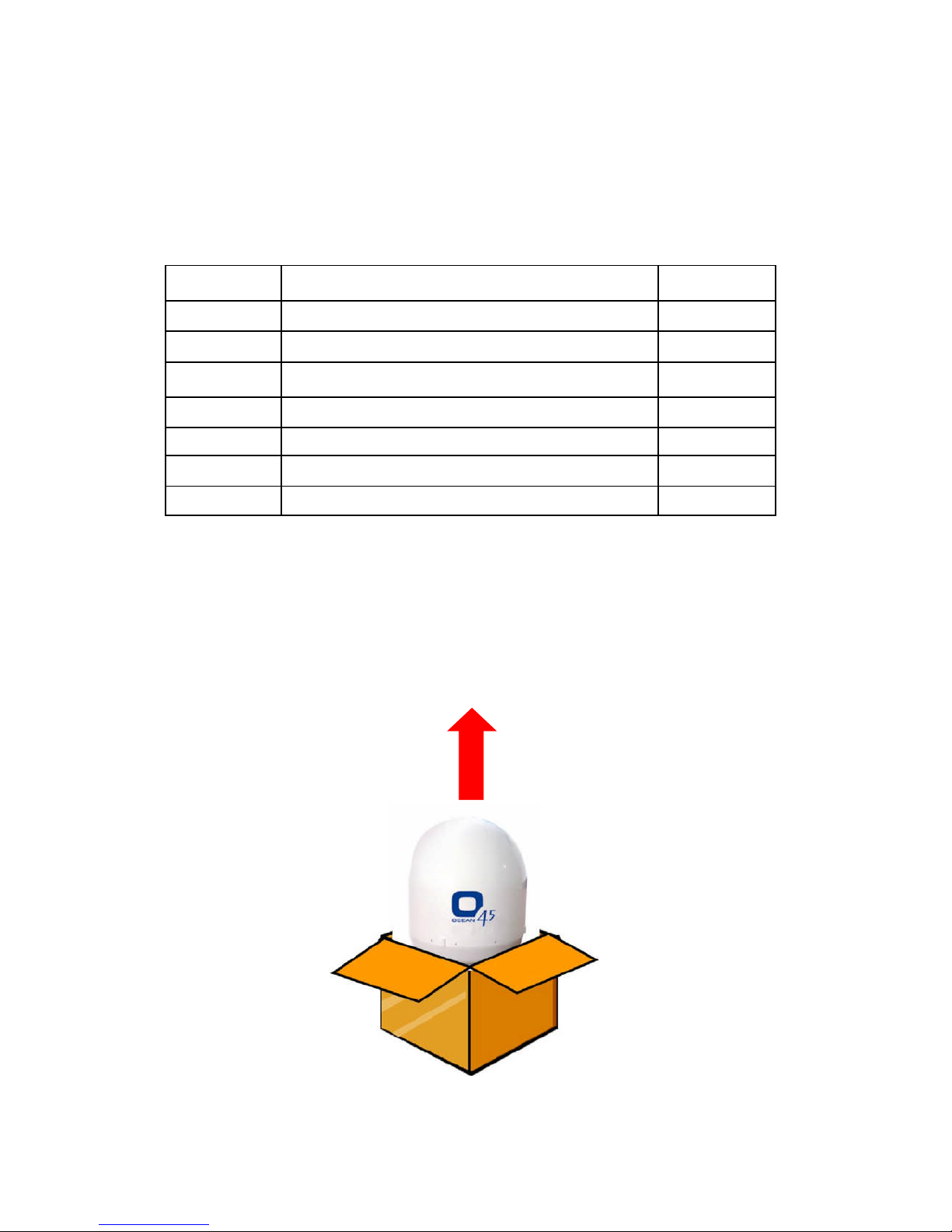
Unpacking the unit
1. Open box and remove packing material.
The following items are included in the packagingof the O37M and O45M antenna.
Item Description Quantity
1 O37M or O45M Antenna Unit 1 each
2 IDU (In Door Unit) 1 each
3 Power Cable 1 each
4 Coaxial Cable (10m) 1 each
5 Coaxial Cable (1m) 1 each
6 Installation & User Manual 1 set
7
CableRight Hand Connectors (O37M Only) 1 Set of 6
Table 2-1 Parts included
2. Lift dome out of box vertically. Do not turn box and “roll” out, or turn upside down to
remove.
Lift Unit straight u p
out of the cart on!
Figure 2-1 Unpacking the unit
Note: Optional approved Cables and accessories are available from Ocean TV.

Ocean TV Ocean Series Antennas
OCEAN TV 10 www.oceantv.com.au
Preparing for the installation
Install Tools and Materials
The O37/45M antenna system is designed for simple installation and setup. However, the following list of equipment or items should be available during installation of the O37/45M antenna.
■ Electric drill and drill bits
■ Socket wrench
■ Silicon sealant
■ Fastener suitable for specific application
1. Verification of the Vessel’s PowerSupply.
■ Confirm that the vessel’s power supply is 12VDC~24VDC.
2. Verification of the Satellite Receiver and IDU’s attachment and the electricity supply
■ Attach Satellite Receiver and IDU in the interior of the vessel or the trunk.
■ Connect thepower of Satellite Receiver and IDU.
■ Once thepower of Satellite Receiver and IDU is verified, it confirms that both Satellite
Receiver and IDU are workingnormally.
3. Procedure of the satellite’s attachment and installation.
■ Attach the satellite on the flat surface area of the vessel’s roof.
■ Connect each end of the Coaxial antenna cable to the satellite’s terminal and the IDU.
■ Connect the IDU and the Satellite Receiver boxtogether through the coaxial cable.
■ Make sure that the satellite is working normally, once the power is supplied.
Warning : Things to consider when installing the antenna.
■ Turn off the power when attachingor detachingthe antenna.
■ Make sure that the attached satellite is fixed on the flat surface.
■ When attaching, ensure that all the products are adhered properly.
■ Ensure that all the cables are connected properly.

Ocean TV Ocean Series Antennas
OCEAN TV 11 www.oceantv.com.au
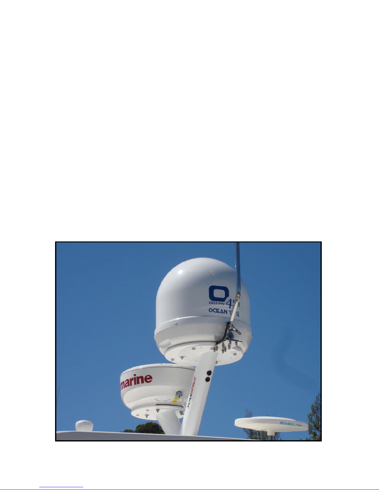
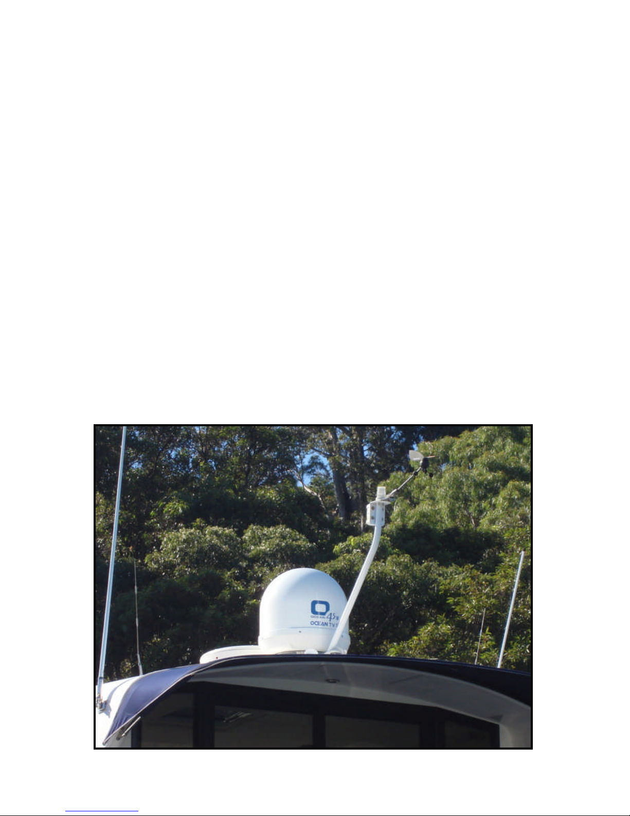
Selecting the location
Determine the optimum mounting location for the antenna radome assembly. It should be
installed where :
1. The antenna has a clear line-of-sight view to as much of the sky as is practical. Choose
a location where masts or other structures do not block the satellite signal from the dish
as the vessel turns.
2. The antenna is at least 5 feet away from other transmitting antennas (HF, VHF and radar) that may generate signals that may interfere with the O37/45M antenna. The further away the O37/45M antenna is from these other antennas, the less impact their operation will have on it.0
3. Direct radiation into the antenna from vessels radar, especially high power surveillance
radar arrays, is minimized. The radome should be as far away from the vessels Radar
as possibleand should NOT be mounted on the same plane as the vessels Radar.
4. The antenna radome assembly should be rigidly mounted to the vessel. If necessary, reinforcethe mounting area to assure that it does not flex due to the vessel motion or vibration.
If these conditions cannot be entirely satisfied, the site selection will inevitably be a “best”
compromise between the various considerations.
Perform a through site inspection on the roof for the antenna to be mounted.
1. The antenna musthave a clear view of the sky and the horizon at all the directions to avoid blockage of thesatellite signal.
2. The antenna should be on the topof the vessel.
Good Location
Best Location
Poor Location
Figure 2-2 Selecting the location
Ocean TV Ocean Series Antennas
OCEAN TV 12 www.oceantv.com.au
Equipment and cable installation
This offers a general explanation of how to install the IDU and satellite receiver properly to the
inside of vessel connectingwith coaxial cable.
1. The Coaxial cable is routed from the antenna to the IDU inside the vessel.
2. After Once deciding where to place the IDU and satellite receiver, make sure that both
units areplaced in a dry and protected area.
3. The IDU and satellite receiver should be placed away from any heat source and in an area
with proper ventilation.
4. Ensure that there areat least 3cm of space around both units for ventilation and connection of cables. Do not stack the units on topof each other.
5. The followingdescribes the basicwiring configurations for the O45M antenna system.
■ Connect the Coaxial cable to the O37/45M antenna port on the back of the IDU
■ Connect one end of the supplied coaxial cable to the receiver port on the back of the
IDU
■ Connect the other end of the coaxial cable to the satellite receiver
Ocean TV Ocean Series Antennas
OCEAN TV 13 www.oceantv.com.au
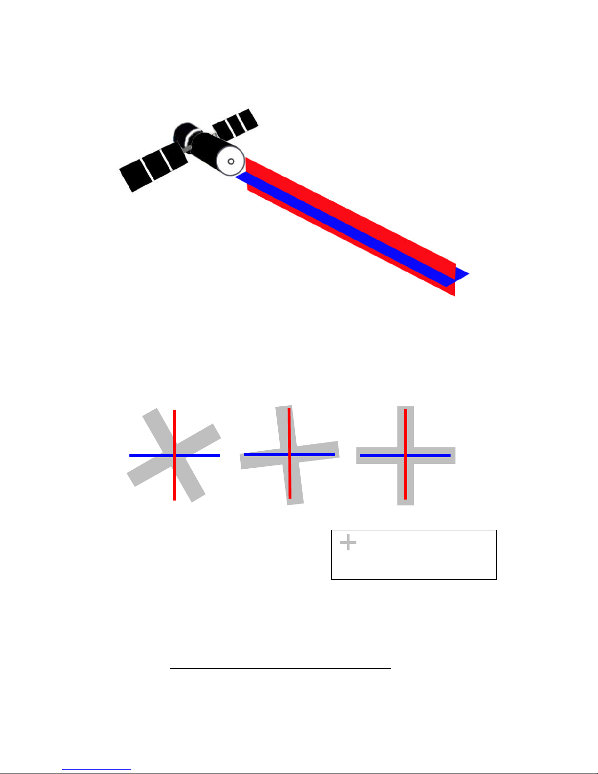
Setting the LNB skewangle (O37M Antenna Only)
Figure 2-3 Satellite signals
Signals transmitted in vertical (red) and horizontal (blue) wave offset exactly 90º from each
other. Since linear satellite signals are oriented in a precise cross pattern, the O45M antenna’s
receiving element, called an LNB (low-noise block) must be oriented in the same way to optiize
reception. This orientation adjustment is referred to as the LNB’s “skew angle.” Figure 2-4
illustrates how skew determines the amount of signal the LNB collects. The more signal, the better the reception.
Figure 2-4 Bes t Skew Angle
Bad skew Good skew Best skew
: LNB “signal collector”
The correct skew setting varies depending on your geographic location, since the orientation of
your antenna to the satellite changes as you move. For complete details about adjusting the
LNB’s skew angle, see “AppendixA– Howto Set theSkewAngle”
All Ocean O37MSkewAngles are preset forAustralian East Coast orNew Zealand
Ocean TV Ocean Series Antennas
OCEAN TV 14 www.oceantv.com.au
The O37M/O45M antenna system is easy to use. Under normal conditions, operation of the
O37M/O45M antenna requires no intervention from the user. Antenna unit initialization and satellite acquisition is completely automatic.
Receiving Satellite TV Signal….……………………………………………………………….. 15
Turning the System On/Off…………………………………………………………….………. 16
Changing Channels…………….……………………………………….………………………….... 17
Watching TV…………………………….…………..……………………………………………….… 17
Switching between Satellites…………………..…………………………………………………. 17
Operating the IDU…..…………………………..…………………………………………………… 18
Operation

Ocean TV Ocean Series Antennas
OCEAN TV 15 www.oceantv.com.au
Receiving Satellite TVSignals
Television satellites are located in fixed positions above the Earth’s equator and beam TV signals
down to certain regions of the planet. To receive TV signals from a satellite, you must be located
within that satellite’s unique coverage area. To check it, see “Appendix B – Satellite Coverage
Map” In addition, since TV satellites are located above the equator, the O37/45M antenna must
have a clear view of the sky to receive satellite TV signals. Anythingthat stands between the antenna and the satellite can block the signal, resulting in lost reception. Common causes of blockage include lighthouses, boat masts, trees, buildings, and bridges. Heavy rain, ice, or snow might
also temporarily interrupt satellite signals.
Turning the System On/Off
Since power to the O37/45M system is controlled by the IDU,you can turn the antenna on or
off by applying/removingoperatingpower to the IDU.
Turning on the System
Follow the steps below to turn on your O37M/45M System.
1. Make sure the antenna has a clear view of the sky.
2.Apply operatingpower to the IDU.
3. Wait one minute for system startup.The IDU will display theTracking Satellite
screen after system testingis complete.
4. Turn on the Satellite TV Receiver Set Top Box (Provided by your Pay TV Provider)
Turning off the System
Follow the steps below to turn offyour O37/45M System.
1. Remove operatingpower from the IDU.
2. Turn offyour satellite TV receiver and TV.
Auto-Sleep
Both the O37M and O45M have an auto sleep mode,. This mode is fully automatic and will
usually happen at the dock after 10 minutes of no movement of the vessel. Occasionally,
when the antenna comes out of auto sleep due to vessel movement, the satellite signal may
be interrupted for a few seconds while the antennas startstrackingthe correct satellite again.
IMPORTANT
It is important to following the following steps in the correct order.
Failure to do so may lead to the satellites not being tracked correctly,
or not tracking at all.
 Loading...