


The Tower™
With Avid Xpress DV
Quick Setup Guide
Document includes:
• Setting up your Tower
• Connecting a digital video deck or camera to your Tower
• Connecting an analog video deck or camera to your Tower
© 2000 Ocean Systems
800-253-7516
www.oceansystems.com
Tower Setup Guide
Setting up your Tower System
Page 1
1.
2.
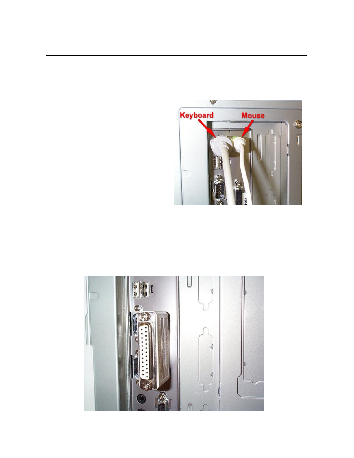
ATTACH MOUSE AND
KEYBOARD
The PS-2 ports are specific.
Be sure to attach the mouse
and keyboard to the ports as
shown in Fig. 1.
ATTACH THE AVID XPRESS
DV HARDWARE LOCK
Fig. 1
The hardware lock (dongle)
attaches to the parallel port as
shown in Fig. 2.
Fig. 2
Tower Setup Guide
Setting up your Tower System
Page 2
3.
4.
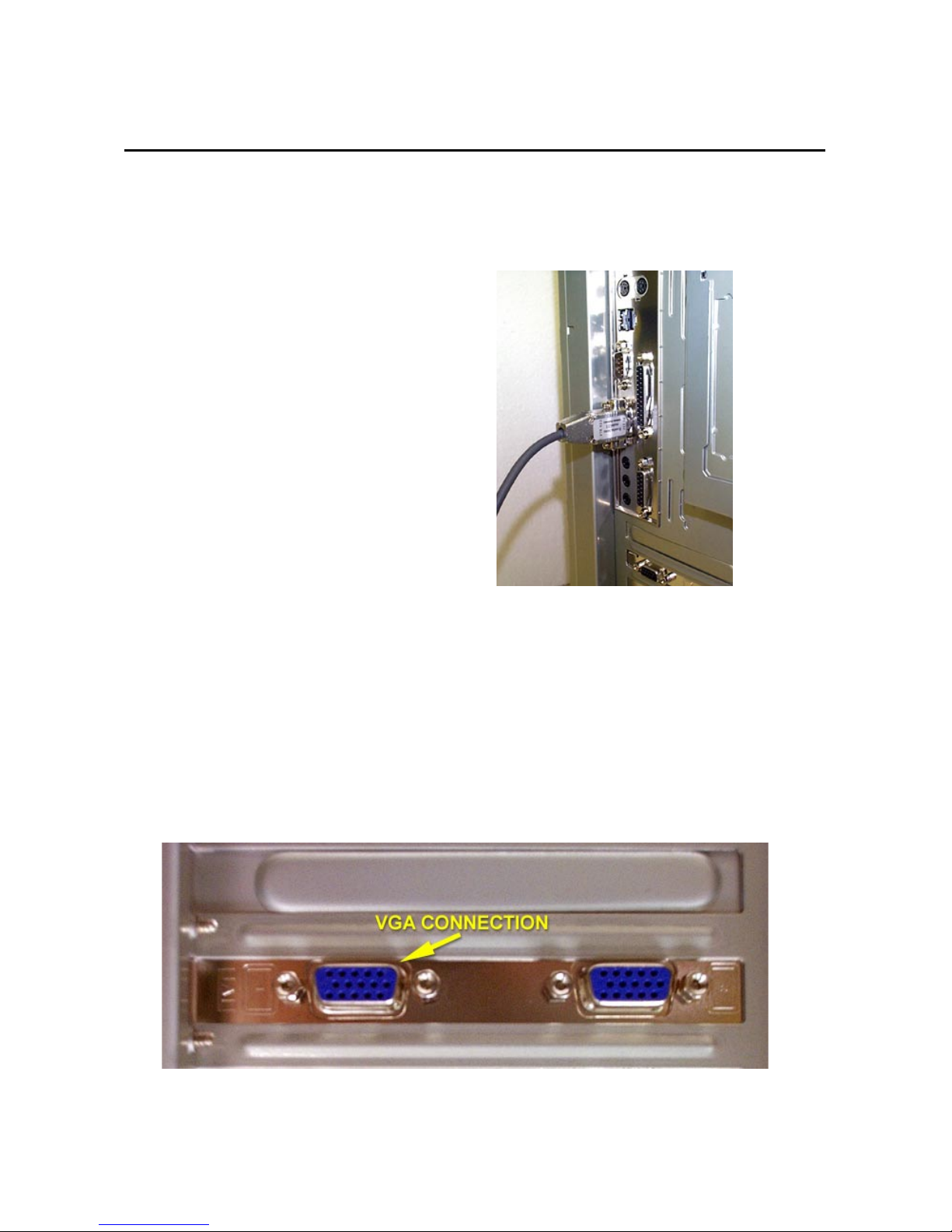
CONNECT YOUR 422/232
CABLE. (FOR ANALOG
DECKS ONLY)
If you are connecting a 422
controllable deck, attach the
422 converter to com1, then
attach the 232 cable from the
converter to your deck. Make
sure the 232 side (silver) is
connected to the tower and the
422 side (grey) is connected to
the deck. This cable is for
analog decks. If you are
utilizing a DV camera or deck,
use your IEEE DV cable for
deck control.
ATTACH THE MONITOR TO
THE VGA CONNECTOR
Fig. 3
Your VGA monitor plugs into the
connection labeled “1” as shown
in Fig. 4.
Fig. 4
Tower Setup Guide
Setting up your Tower System
Page 3
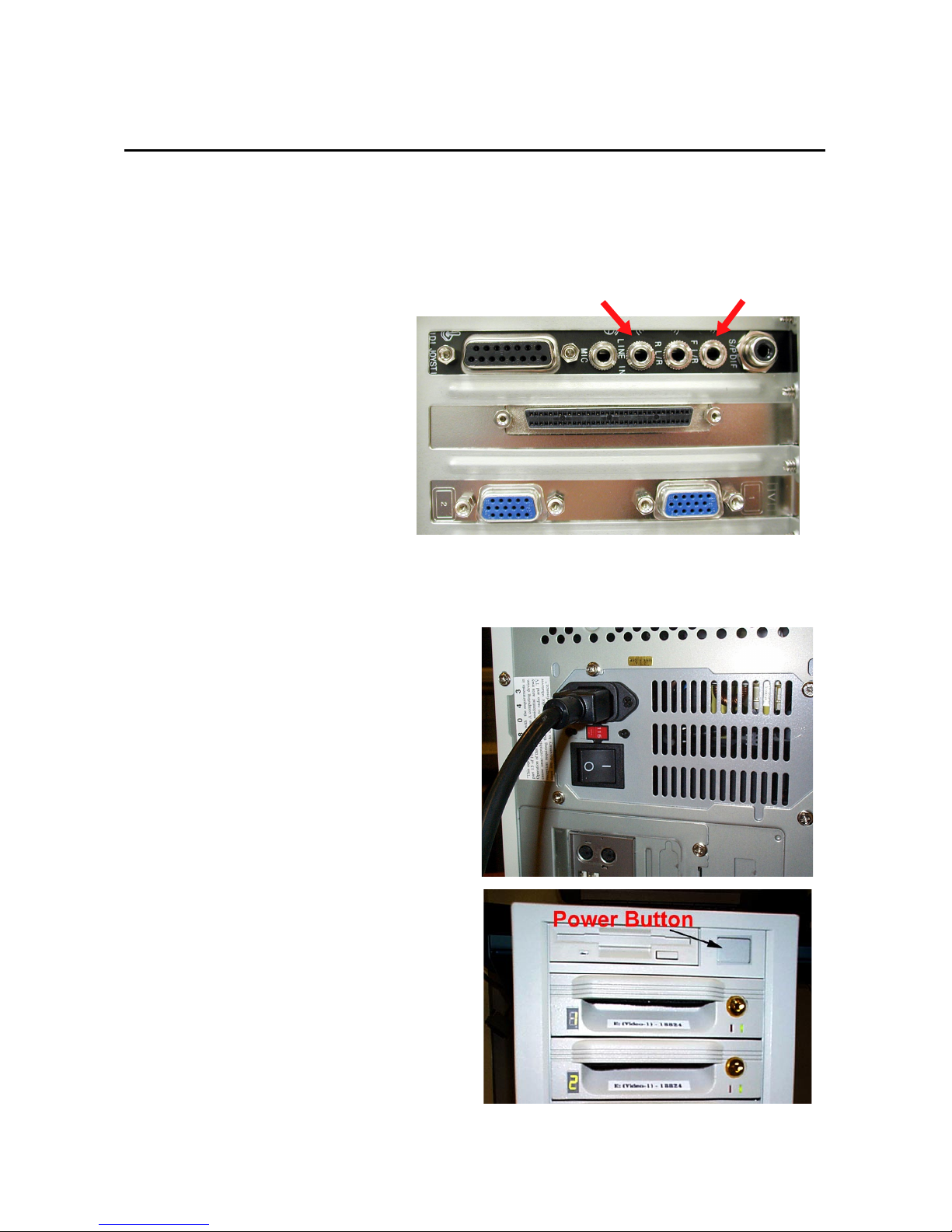
CONNECT YOUR
5.
AUDIO I/O
Fig 5 shows the audio
connections both in and out of
the system. Use the port
labeled “F L/R” to connect audio
to your speakers. To bring
audio into your system (from a
deck, camera, or transcoder),
use the port labeled “Line In”.
You must have audio going
into the system through the
“Line In” port to monitor any
audio you are digitizing.
PLUG IN THE SYSTEM AND
6.
TURN IT ON.
Plug the power cable in as
shown in Fig. 5.
Connect audio from playback
device (deck, transcoder) to the
“Line In” Port to monitor audio as
it’s digitized
Connect speakers to
the F L/R port
Fig. 5
Fig. 6
Fig 5A shows the power button
on the front of The Tower.
Fig. 5A

Tower Setup Guide
Page 4
Connecting a Digital Video Deck or Camera
To connect a digital video deck or camera, you need to have the
provided A/V cables from your digital video deck or camera and the
capture board available. Follow each step and make sure to connect
both the DV and the analog cables.
Step Description
1.
Connect the DV cable from the digital
deck or camera to the capture board.
Connect a 4-pin to 4-pin DV-to-DV cable
from the digital deck or camera to the DV
port on the capture board. This provides DV
video and audio to and from the capture
board. This cable must remain connected to
use the hardware codec in the camera for
display during editing.

Tower Setup Guide
Page 5
Connecting a Digital Video Deck or Camera
Step Description
2.
2a
2b
Connect the analog video from the digital
deck or camera to the capture board.
Connect an RCA-to-RCA cable from the
camera to the in1 port on the capture
board.
Connect an S-Video-to-S-Video cable
from the camera to the in2 port on the
capture board.
Connect the analog signal with either an
RCA cable (step 2a) or an S-Video cable
(step 2b). Perform step 2a or step 2b, not
both.
Provides a composite analog signal from
the hardware codec of the camera to the
In1 port on the capture board. The signal is
looped to the Out1 port and used as a
composite output of the capture board to
the client monitor (your TV or NTSC monitor).
Same as step 2a except the signal uses the
In2 and Out2 ports.

Tower Setup Guide
Page 6
Connecting a Digital Video Deck or Camera
Step Description
3.
3a
3b
Connect the capture board to the
optional Client monitor.
Connect an RCA cable to the Out1 port
on the capture board.
Attach the other end of the cable to the
Client monitor.
Connect a cable with an S-Video
connector to the Out2 port on the
capture board.
Attach the other end of the cable to the
Client monitor.
Connect the Client monitor with either an
RCA cable (step 3a) or S-Video cable (step
3b).
Provides composite analog video from the
Out1 port, looped from the In1 port
connection, to the Client monitor. You can
see the incoming video during the record
process and when you play a clip, as
explained in step 2a.
Same as step 3a except the signal uses the
In2 and Out2 ports.

Tower Setup Guide
Page 7
Connecting a Digital Video Deck or Camera
Step Description
4
Connect the audio Out of your camera or
deck to the Audio in at the rear of your
Ocean Systems Xpress DV editing
system.
Provides audio output to the speakers
during the record process or when you are
playing a clip.
Make sure you have already connected your
provided speakers.

Tower Setup Guide
Page 8
Connecting an Analog Video Deck or Camera
An analog video deck connects to the Sony transcoder, and the
transcoder connects to the Ocean Systems editing system. You need
the cables from your camera and the capture board available.
Step Description
1.
Connect the video and audio cables from
an analog video deck to the input of the
Sony transponder.
Provides an analog signal to be recorded
and used as DV data. It also allows the
composite video signal and analog audio
signal to be sent from the transcoder back to
the deck when you output the edited file.

Tower Setup Guide
Page 9
Connecting an Analog Video Deck or Camera
Step Description
2
Connect the DV cable from the Sony
transcoder to the capture board.
Connect a 4-pin to-4-pin DV-to-DV cable
from the Sony transcoder to the DV port on
the capture board. This provides DV video
and audio to and from the capture board.
This cable must remain connected to use
the hardware codec in the Sony transcoder
for display during editing.

Tower Setup Guide
Page 10
Connecting an Analog Video Deck or Camera
Step Description
3
3a
3b
Connect the analog video from the
transcoder to the capture board
Connect an RCA-to-RCA cable from the
Sony transcoder to the In1 port on the
capture board.
Connect an S-Video to S-Video cable
from the Sony transcoder to the In2 port
on the capture board.
Connect the analog signal with either an
RCA cable (step 3a) or an S-Video cable
(step 3b), not both.
Provides a composite analog signal from the
hardware codec of the transcoder to the In1
port on the capture board. The signal is
looped to the Out1 port and used as a
composite output of the capture board to the
Client monitor.
This signal will also loop through via the DV
connection as a VGA overlay.
Same as step 3a except the signal uses the
In2 and Out2 ports.

Tower Setup Guide
Page 11
Connecting an Analog Video Deck or Camera
Step Description
4
4a
4b
Connect the Client monitor to the capture
board.
Connect an cable with an RCA connector
to the Out2 port on the capture board.
Attach the other end of the cable to the
Client monitor.
Connect a cable with an S-Video
connector to the Out2 port on the
capture board.
Attach the other end of the cable to the
Client monitor.
Connect the Client monitor with either an
RCA cable (step 4a) or S-Video cable (step
4b).
Provides composite analog video from the
Out1 port, looped from the In1 port
connection, to the client monitor. You can
see the incoming video during the record
process and when you play a clip, as
explained in step 3a.
Same as step 4a except the signal uses the
In2 and Out2 ports.

Tower Setup Guide
Page 12
Connecting an Analog Video Deck or Camera
Step Description
5
Connect the Audio Out of your Sony
transcoder to Audio In at the rear of the
Ocean Systems Xpress DV editing
System. You can use the cables that
came with your transcoder.
Provides audio output to the speakers
during the record process or when you are
playing a clip
 Loading...