

Q-Boat I
Assembly and
Operating
Instructions
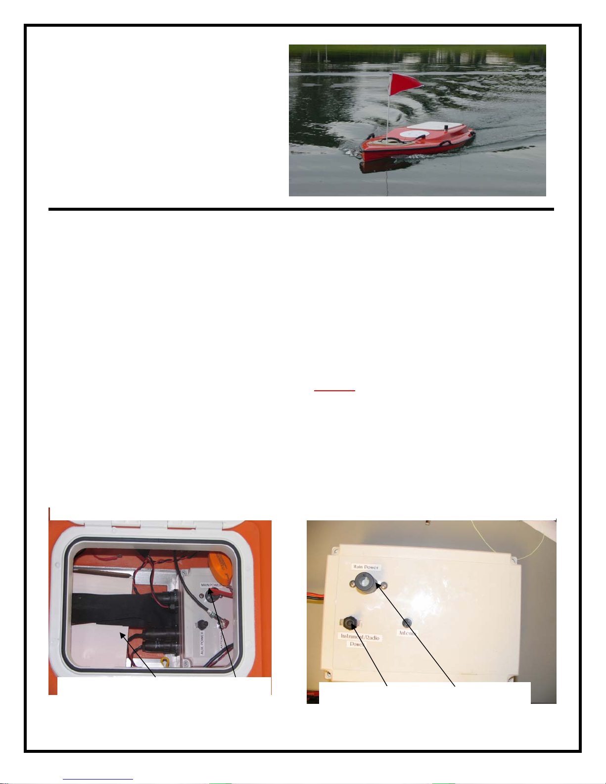
The Oceanscience Q-Boat I is a remotely
controlled electric boat designed for easy sensor
deployment. It has two 12VDC motors and a
top speed near 1.7 mps. The Q-Boat is
configured to accept optional Hydrolink radio
modems. A generous space for data electronics
is located below deck. Following are
instructions for set up and operation of the boat
with a standard ADCP.
Battery Installation
The Q-Boat I uses a single high-energy 12V
30Ah NiMH battery. The battery is nested in a
fiberglass bracket below the main deck hatch
and strapped in place with Velcro straps. Be
sure the main power switch is off when loading
and unloading the battery (See Figure 1).
Control Electronics
The QB-I is operated using a commercial offthe-shelf Futaba transmitter/receiver or the
Oceanscience Vessel Control System. Please
refer to the controller manual for instruction.
The onboard Vessel Control Unit (VCU, see
Figure 2) holds a speed controller and control
radio receiver. The VCU also provides a 12VDC
auxiliary power port for powering standard
instrumentation equipment (including data
transmission radios).
Operation
Caution:
There is extreme danger of injury if they are
touched or otherwise contacted while operating.
Always stay clear of the propellers when
batteries are onboard.
Oceanscience recommends that you familiarize
yourself with the control system operation before
deployment.
The propellers turn at over 1500 RPM.
Figure 1. Battery(s) Power Switch
Q-Boat Assembly and Operating Instructions
August, 2008
The Oceanscience Group
760 754 2400
www.oceanscience.com
Figure 2 Auxiliary Power Main Power

Controller Range Test
Before deploying the boat, test the controller
range by powering up, confirming operation,
and then walking away from the boat while an
observer at the boat confirms continuous
contact. Be sure to check onboard antenna
connections and to fully extend the handheld
controller antenna.
Other Tips
Before deploying in fast rivers or dangerous
situations, thoroughly familiarize yourself with
the way the boat responds to the controls.
When the boat is outbound, it will respond to
control signals much as expected. When
inbound (heading towards the handheld unit)
the same control signals create an opposite
response. During inbound transit, it will help to
leave the settings unchanged and to hold your
attention constantly on the boat.
Without sufficient practice, the usual first
response in an emergency inbound maneuver is
likely to be opposite the desired direction.
Make small changes with the throttle and
steering controls. They are sensitive and gentle
operation is all that’s needed to make the boat
respond.
To prolong the life of the motors and propulsion
system, accelerate slowly and gently. The
rudder servo consumes a lot of power;
minimizing rudder use will extend the power
endurance.
Power Up Process & Deployment
Caution: Follow the correct power-up process
to avoid mishaps. Always activate the handheld
controller first. Activating the on-board power
switches with the handheld controller turned off
could instantly activate the rudders and props to
pre-set speeds. This is potentially dangerous.
Step 1. Before powering the boat, confirm that
Q-Boat Assembly and Operating Instructions
August, 2008
The Oceanscience Group
760 754 2400
www.oceanscience.com
the handheld controller/wireless helm is turned
on, the props are clear, no one is standing near
the boat, and that the control sticks are in
neutral.
Step 2. Turn on the on-board power switches.
Note the two switches on the lid of the
electronics box in Figure 2: Main Power and
Auxiliary Power switch (forward). The main
power switch does not have to be on for the auxiliary
switch to provide power to the auxiliary port.
Step 3. Before launching the boat, test forward
and reverse propeller operation to ensure
correct function. Move the rudder control (left
joystick) back and forth to make sure that the
rudder is working and that it doesn’t bind at
either lock. When ready to deploy, we
recommend backing the boat away from the
shore to minimize the potential for prop
damage.
Installing the ADCP
With the ADCP looking downward and sitting
on its cap, install the ¼-20 x 3”mounting studs:
insert the studs from above and install a lock
washer and standard nut on the bottom, leaving
no more thread than necessary protruding from
the bottom of the nut. (see Figure 4). Install a
hex nut from the top, using wrenches to snug
both nuts against the instrument flange. This
will leave about ¾” of thread protruding
upwards to pass through the instrument
mounting plate and receive the wing nuts and
lock washers.
Attach the mounting plate to the instrument,
and place instrument with mounting plate
attached into the well on the Q-Boat. Adjust for
height with standoffs if needed and secure the
mounting plate to the boat. Connect the
instrument cable to the ADCP and internally to
the modem.

Driveline Maintenance
The Q-Boat is shipped with prop shafts fully
greased. For optimum performance and leak
prevention it is important that they remain so.
The shafts have grease fittings for regular
service. Replenish the grease at least once a
week when the boat is being used, and before
any deployment following an inactive period.
Use lithium trailer axle grease (a grease kit is
included; replacement grease may be obtained
at a marine supply store).
Battery Charging
The Q-Boat 1 uses a 12V 30Ah NiMH battery to
provide three sources of power: 12V propulsion,
12V instrumentation, and 4.8/6V power for onboard radio controller/rudder servo power.
The 30 AH battery uses a specialized charger
and the charging instructions should be
followed closely. NOTE: At no time can the
battery be charged with the 3-1 discharge cable
attached. The charger should require a minimum
of 15 hours to charge with the charger rate
selector switch in the 1.9A position. Spare
propulsion batteries may be purchased from any
local battery distributor. A 12V AGM battery
with between 30 and 40 AH capacity is an
acceptable alternative.. Chargers for these
batteries may also be purchased locally.
Hand-held Controller
The handheld controller/wireless helm uses its
own batteries that need to be maintained and
properly charged. Batteries and charger are
provided. Please refer to the controller manual.
Figure4.ADCPwithmountingboltsinstalled.
Q-Boat Assembly and Operating Instructions
August, 2008
The Oceanscience Group
760 754 2400
www.oceanscience.com

Q-Boat Assembly and Operating Instructions
August, 2008
The Oceanscience Group
760 754 2400
www.oceanscience.com
 Loading...