

OceanSat AIS User Manual

bVcjVa

Thank you for purchasing this AIS Class A transceiver / Inland AIS.
This product has been engineered to offer you the highest level of performance and
durability and we hope that it will provide many years of reliable service. We constantly
strive to achieve the highest possible quality standards, should you encounter any
problems with this product, please contact your dealer who will be pleased to offer any
assistance you require.

Page 3
Contents
1 Notices..............................................................................................7
1.1 Safety warnings ............................................................................................................................ 7
1.2 General notices............................................................................................................................. 7
1.3 Revision information ..................................................................................................................... 8
2 Introduction......................................................................................9
2.1 About AIS...................................................................................................................................... 9
2.2 Static and dynamic vessel data .................................................................................................. 10
2.3 AIS operation licensing ............................................................................................................... 10
3 Operation........................................................................................11
3.1 Display and controls.................................................................................................................... 11
3.2 Turning the transceiver on .......................................................................................................... 12
3.3 Display layout.............................................................................................................................. 12
3.4 Main operating screens............................................................................................................... 13
3.5 Target list .................................................................................................................................... 14
3.6 Own vessel and voyage data...................................................................................................... 14
3.7 Own dynamic data ...................................................................................................................... 15
3.8 Received messages.................................................................................................................... 16
3.9 Alarms screen ............................................................................................................................. 17
3.10 Target plot screen ....................................................................................................................... 18
3.11 Working with AIS text and Safety Related Messages (SRMs).................................................... 18
3.12 Handling alarms .......................................................................................................................... 20
3.13 Entering text................................................................................................................................ 21
3.14 Long range messages ................................................................................................................ 22
3.15 Passwords and security .............................................................................................................. 24
3.16 The configuration menu .............................................................................................................. 24
3.17 Inland AIS ................................................................................................................................... 29
4 Installation......................................................................................31
4.1 What’s in the box? ...................................................................................................................... 32
4.2 Preparing for installation ............................................................................................................. 33
4.3 Installation procedures................................................................................................................ 33
4.4 Connecting the equipment.......................................................................................................... 39
4.5 Configuring the AIS-100 transceiver ........................................................................................... 46
4.6 Changing the password .............................................................................................................. 49
4.7 Confirming correct operation....................................................................................................... 49
4.8 Regional area settings ................................................................................................................ 49
4.9 Inland AIS ................................................................................................................................... 51
5 Technical Specifications...............................................................55
5.1 Applicable equipment standards................................................................................................. 55
5.2 Physical ...................................................................................................................................... 55
5.3 Environmental ............................................................................................................................ 55
5.4 Electrical .................................................................................................................................... 55
5.5 Display and user interface ......................................................................................................... 56

Page 4
5.6 Internal GPS .............................................................................................................................. 56
5.7 TDMA transmitter ....................................................................................................................... 56
5.8 TDMA receivers .......................................................................................................................... 56
5.9 DSC receiver............................................................................................................................... 57
5.10 RF connections ........................................................................................................................... 57
5.11 Data interfaces............................................................................................................................ 57
5.12 Power and data connector information ....................................................................................... 58
6 Technical reference.......................................................................59
6.1 Interface sentences..................................................................................................................... 59
6.2 Transmission intervals ................................................................................................................ 60
6.3 Sensor data input port................................................................................................................. 60
6.4 Bi-directional data ports .............................................................................................................. 61
6.5 Output drive capability of bi-directional ports ..............................................................................61
6.6 DGPS port................................................................................................................................... 61
6.7 RS232 port.................................................................................................................................. 61
6.8 Input data sentence formats ....................................................................................................... 61
6.9 Output data sentence formats..................................................................................................... 70
7 Drawings ........................................................................................74
7.1 AIS transceiver overall dimensions............................................................................................. 74
7.2 Junction box overall dimensions ................................................................................................. 74
7.3 Dash mount bracket fixing holes (drill drawing) (not to scale) .................................................... 75
7.4 GPS antenna drawing (not to scale)...........................................................................................75
8 Annex A - ERI Ship types..............................................................76
9 Installation record .........................................................................79
10 Warranty .........................................................................................83

Page 5
List of figures
Figure 1 The AIS network ................................................................................................................. 9
Figure 2 Transceiver front panel ..................................................................................................... 11
Figure 3 Display layout ................................................................................................................... 12
Figure 4 Selection of main operating screen .................................................................................. 13
Figure 5 Target list screen and vessel details view ........................................................................ 14
Figure 6 Own vessel and voyage data screen................................................................................ 14
Figure 7 Own dynamic data screen ................................................................................................ 15
Figure 8 Received messages screen.............................................................................................. 16
Figure 9 Message details view........................................................................................................ 16
Figure 10 Alarms screen................................................................................................................... 17
Figure 11 Alarm details view............................................................................................................. 17
Figure 12 Target plot screen............................................................................................................. 18
Figure 13 Target plot symbols .......................................................................................................... 18
Figure 14 Safety Related Message notification ................................................................................ 19
Figure 15 Message composition....................................................................................................... 19
Figure 16 Alarm notification screen .................................................................................................. 20
Figure 17 Text entry.......................................................................................................................... 22
Figure 18 Long range interrogation notification; automatic response mode enabled ....................... 23
Figure 19 Long range interrogation notification; manual response mode enabled ........................... 23
Figure 20 Long range message list and details views ...................................................................... 23
Figure 21 Password entry screen ..................................................................................................... 24
Figure 22 Main menu structure ......................................................................................................... 25
Figure 23 Main menu screen ............................................................................................................ 26
Figure 24 The voyage data menu ..................................................................................................... 26
Figure 25 The messages menu ........................................................................................................ 27
Figure 26 The user settings menu .................................................................................................... 27
Figure 27 The installation menu........................................................................................................ 28
Figure 28 The maintenance menu .................................................................................................... 28
Figure 29 Diagnostics menu ............................................................................................................. 29
Figure 30 Typical AIS transceiver connection................................................................................... 31
Figure 31 What’s in the box .............................................................................................................. 32
Figure 32 AIS transceiver dimensions .............................................................................................. 34
Figure 33 Mounting the AIS transceiver............................................................................................ 34
Figure 34 Panel mounting the AIS transceiver ................................................................................. 35
Figure 35 Junction box dimensions .................................................................................................. 36
Figure 36 Mounting the junction box................................................................................................. 36
Figure 37 GPS antenna location....................................................................................................... 37
Figure 38 GPS antenna connection.................................................................................................. 37
Figure 39 VHF antenna installation................................................................................................... 38
Figure 40 VHF antenna connection .................................................................................................. 39
Figure 41 Connecting the junction box to the transceiver................................................................. 39
Figure 42 Junction box connections ................................................................................................. 41
Figure 43 Example connection to external display equipment.......................................................... 43
Figure 44 Line termination options.................................................................................................... 43
Figure 45 Power connection ............................................................................................................. 44
Figure 46 PC data (RS232) connection............................................................................................ 45
Figure 47 Vessel dimensions measurement..................................................................................... 47
Figure 48 Regional areas list screen ................................................................................................ 49
Figure 49 Regional area editing screen ............................................................................................ 50
Figure 50 Regional area settings confirmation screen...................................................................... 50
Figure 51 Blue sign switch connection.............................................................................................. 53
Figure 52 Input port schematic ......................................................................................................... 60
Figure 53 Data output port schematic............................................................................................... 61

Page 6
Notices
Page 7
1 Notices
When reading this manual please pay particular attention to warnings marked with the
warning triangle symbol shown on the left. These are important messages for safety,
installation and usage of the transceiver.
1.1 Safety warnings
1.2 General notices
1.2.1 Position source
All marine Automatic Identification System (AIS) transceivers utilise a satellite based location system such as
the Global Positioning Satellite (GPS) network.
The general term for satellite based location systems is Global Navigation Satellite System or GNSS. This
manual refers to either GNSS or GPS depending on context.
1.2.2 Compass safe distance
The compass safe distance of this transceiver is 0.3m or greater for a 0.3° deviation.
1.2.3 Product category
This product is categorised as ‘protected’ in accordance with the definitions provided in IEC 60945.
The accuracy of a GPS position fix is variable and affected by factors such as the antenna
positioning, how many satellites are used to determine a position and for how long satellite
information has been received.
This equipment must be installed in accordance with the instructions provided in this manual. Failure
to do so will seriously affect its performance and reliability. It is strongly recommended that a trained
technician installs and configures this product.
This equipment is intended as an aid to navigation and is not a replacement for proper navigational
judgement. Information provided by the equipment must not be relied upon as accurate. User
decisions based upon information provided by the equipment are done so entirely at the users own
risk.
Do not install this equipment in a flammable atmosphere such as in an engine room or near to fuel
tanks.
Do not attempt to service this equipment as doing so may cause fire, electric shock or malfunction and
will invalidate the warranty. If any malfunctions are detected contact your supplier or service agent.
Do not install the transceiver where rain or water may leak onto the equipment. This product has been
designed for installation and use in an environment protected from moisture.
NOT ALL SHIPS CARRY AIS. The Officer of the Watch (OOW) should always be aware that other
ships and, in particular, leisure craft, fishing vessels and warships may not be fitted with AIS. Any AIS
equipment fitted on other ships as a mandatory carriage requirement may also be off based on the
Master’s professional judgement.
It is recommended that this product is not installed in direct sunlight or under a windshield where it can
be subjected to excessive solar heating.

Notices
Page 8
1.2.4 Disposal of the transceiver and packaging
Please dispose of this AIS transceiver in accordance with the European WEEE Directive or with the applicable
local regulations for disposal of electrical equipment. Every effort has been made to ensure the packaging for
the transceiver is recyclable. Please dispose of the packaging in an environmentally friendly manner.
1.2.5 Accuracy of this manual
This manual is intended as a guide to the installation, setup and use of this product. Every effort has been made
to ensure the accuracy of this manual, however due to continuous product development this manual may not
be accurate in all respects, therefore no guarantee is offered. If you are in any doubt about any aspect of this
product, please contact your dealer.
Manual version number: 1.0
1.2.6 Marine Equipment Directive
The Oceansat transceiver complies with international standards and is type approved in accordance with the
European Marine Equipment Directive. The EU Declaration of Conformity is provided at the rear of this manual
and lists the relevant approval standards.
1.3 Revision information
This manual applies to the following transceiver hardware and software versions:
● Transceiver software version 030200.05.00.00
● Display software version 030400.02.00.00
● Hardware version 4.0
Notified Body No: 0168
Year: 2010
Introduction
Page 9
2Introduction
2.1 About AIS
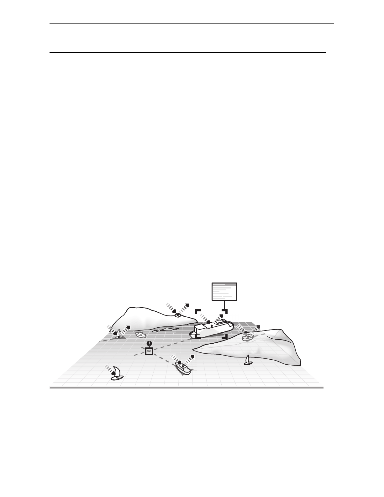
The marine Automatic Identification System (AIS) is a location and vessel information reporting system. It
allows vessels equipped with AIS to automatically and dynamically share and regularly update their position,
speed, course and other information such as vessel identity with similarly equipped vessels. Position is derived
from the Global Positioning System (GPS) and communication between vessels is by Very High Frequency
(VHF) digital transmissions.
There are a number of types of AIS device as follows:
● Class A transceivers. These are designed to be fitted to commercial vessels such as cargo ships
and large passenger vessels. Class A transceivers transmit at a higher VHF signal power than class
B transceivers and therefore can be received by more distant vessels, and also transmit more
frequently. Class A transceivers are mandatory on all vessels over 300 gross tonnes on international
voyages and certain types of passenger vessels under the SOLAS mandate.
● Inland AIS stations. Similar to class A transceivers with additional features for use on Inland
waterways.
● Class B transceivers. Similar to Class A transceivers in many ways, but are normally lower cost due
to the less stringent performance requirements. Class B transceivers transmit at a lower power and at
a lower reporting rate than Class A transceivers.
● AIS base stations. AIS base stations are used by Vessel Traffic Systems to monitor and control the
transmissions of AIS transceivers.
● Aids to Navigation (AtoN) transceivers. AtoNs are transceivers mounted on buoys or other
hazards to shipping which transmit details of their location to the surrounding vessels.
● AIS receivers. AIS receivers receive transmissions from Class A transceivers, Class B transceivers,
AtoNs and AIS base stations but do not transmit any information about the vessel on which they are
installed.
The Oceansat transceiver is a combined Class A transceiver / Inland AIS.
Figure 1 The AIS network

Introduction
Page 10
2.2 Static and dynamic vessel data
Information transmitted by an AIS transceiver is in two categories: static and dynamic data.
The vessel's dynamic data which includes location, speed over ground (SOG) and course over ground (COG) is
calculated automatically using the internal GPS receiver.
Static data is information about the vessel which must be programmed into the AIS transceiver. This includes:
● Maritime Mobile Service Identity (MMSI)
● Vessel name
● Vessel call sign (if available)
● Vessel type
● Vessel dimensions
2.3 AIS operation licensing
In most countries the operation of an AIS transceiver is included under the vessel's marine VHF licence provisions. The
vessel on to which the AIS transceiver is to be installed must therefore possess a current VHF radiotelephone licence
which lists the AIS system, vessel Call Sign and MMSI number. Please contact the relevant authority in your country for
further information regarding ship’s radio licensing requirements.

Operation
Page 11
3Operation
This section assumes that the Oceansat transceiver has been installed in accordance with the instructions
provided in the Installation section of this manual.
Please read the warning notices at the front of this manual before operating the AIS transceiver.
3.1 Display and controls
Figure 2 Transceiver front panel
The front panel of the transceiver is shown in Figure 2 with each control marked.
Menu key
This key provides access to the transceiver set up and configuration menu from any operating screen.
Back key
This key cancels the current operation, moves to the previous menu level or acts as a backspace key
depending on the operation being carried out.
Scroll wheel
The scroll wheel is used to select information presented on the display, select menu items and edit text and
numeric information shown on the screen. The scroll wheel can also be pressed to confirm data entry or select
information presented on the display.
Right and left function keys
The function of these keys is shown in the display area directly above each key. The function depends on the
operation being carried out.
Sounder
The Sounder provides an audible ‘beep’ when a key is pressed. Key beeps can be activated or deactivated via
the User Settings menu.
Pilot Plug
The Pilot Plug provides an AIS connection for pilots using the IMO standard Pilot Plug connector.
Display
The display shows essential AIS operating information and allows for configuration of the transceiver. It is
recommended that the transceiver is connected to a compatible Radar or Electronic Chart Display System
(ECDIS) for monitoring of AIS vessels during navigation.
Display
Sounder
Menu key
Back key
Scroll wheel
Right function key
Pilot plug (behind protective cover)
Left function key
Operation
Page 12
3.2 Turning the transceiver on
The Oceansat transceiver does not have a power switch and is designed to be permanently powered. When
power is first applied the display will show a splash screen followed by software version information. Each
screen is shown for 5 seconds before the main operating screen is shown.
3.3 Display layout
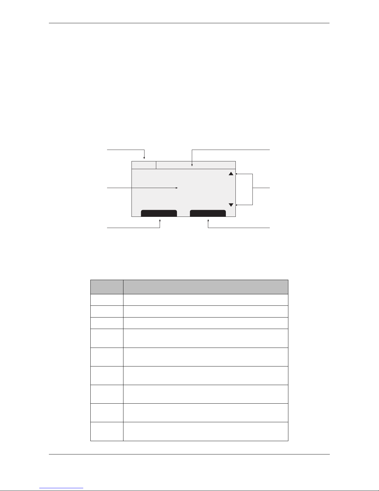
The display layout is shown in Figure 3. All operating screens show the time, status bar, scroll indicators and
relevant function keys. The time displayed is UTC time.
When no UTC time is available from the internal GNSS module the time display will show --:--:-- in place of the
time of day.
Figure 3 Display layout
3.3.1 Status bar icons
The status bar shows the current transceiver status using icons. The meaning of each icon is described in Table 1.
Icon Description
OK The transceiver is operating normally.
Tx Shown for one second following each transmission.
Rx Shown for one second following each received message.
INT
GPS
Shown when the internal GPS receiver has a valid position
fix.
EXT
GPS
Shown when a connected external GPS receiver has a valid
position fix.
INT
DGPS
Shown when the internal GPS receiver has a valid differential
position fix.
EXT
DGPS
Shown when a connected external GPS receiver has a valid
differential position fix.
NO
GPS
Shown when there is no valid internal or external position fix.
Shown when unread AIS safety related text messages are
available.
HH:MM:SS
Select Screen
Main display area
UTC time
Left function key
Scroll indicators
Status bar
Right function key
Operation
Page 13
Table 1 Status Icons
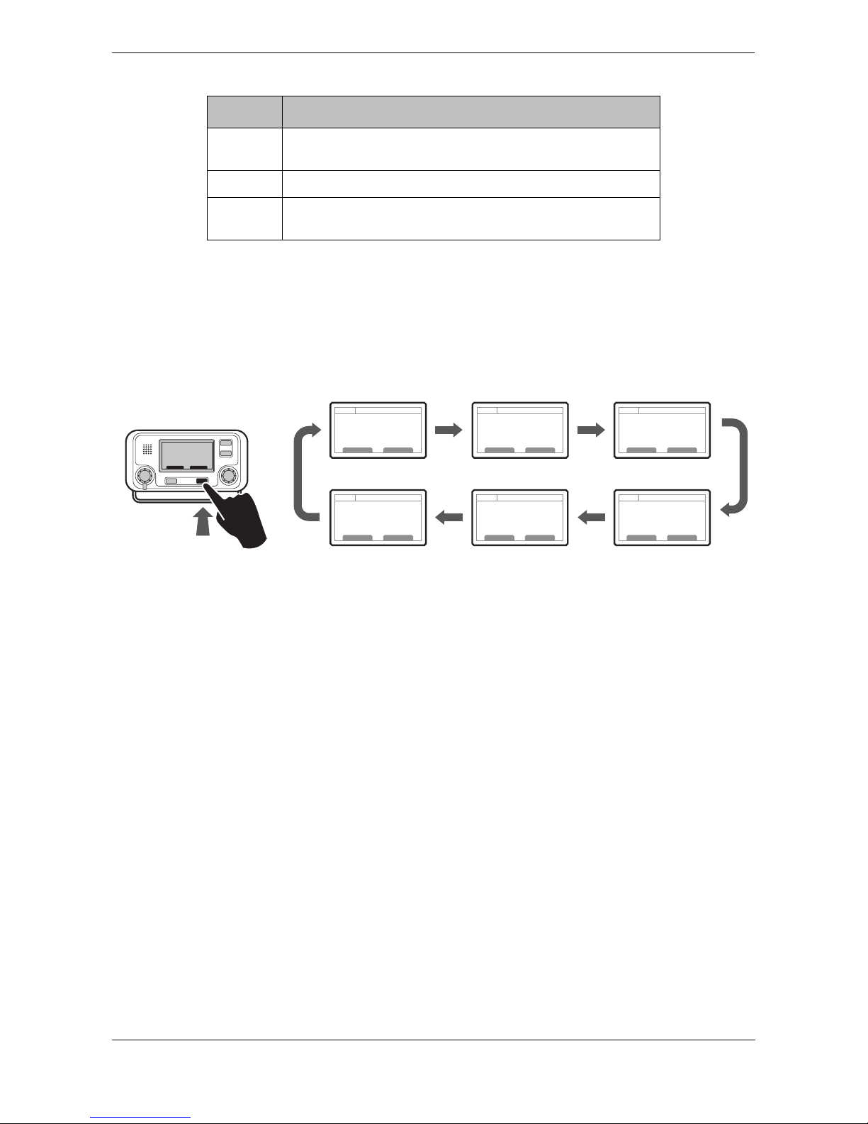
3.4 Main operating screens
In normal operation the display shows one of six main operating screens. The next screen can be selected at
any time by pressing the ‘Screen’ function key as shown in
Figure 4. The following subsections describe each
of the operating screens in more detail.
Figure 4 Selection of main operating screen
Shown flashing when an alarm is active, shown constantly
when an alarm is active, but acknowledged.
1W Shown when the transmitter is set to 1W mode.
IL Shown when the AIS transceiver is operating in ‘Inland
Waterways’ mode.
Icon Description
Target list Own vessel &
voyage data
Own dynamic
data
AlarmsTarget plot Received
messages
Operation
Page 14
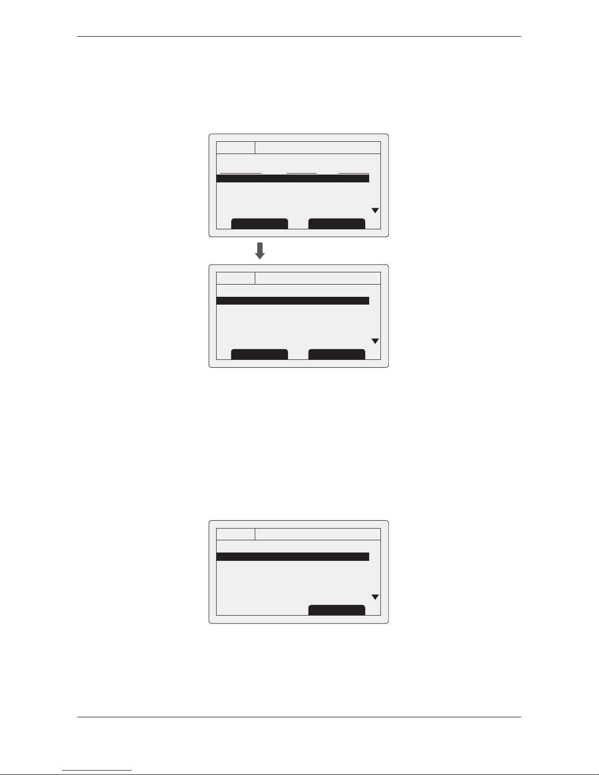
3.5 Target list
The target list screen is shown by default after power up. This screen shows the name (or MMSI), range (in
nautical miles) and bearing (in degrees) of other AIS equipped vessels. The nearest vessel is shown at the top
of the list. Only the 200 nearest vessels are shown in the target list, more distant vessels may be viewed if an
AIS enabled external display, RADAR or ECDIS is connected to the
transceiver.
Figure 5 Target list screen and vessel details view
When the target list screen is displayed the scroll wheel can be used to move through the list. Full details of
the highlighted vessel can be shown by pressing the ‘Select’ function key, or pushing the scroll wheel. To return
to the target list from the vessel details screen press the ‘Back’ key. Whilst the vessel details screen is displayed
it is possible to view details of the next and previous vessels in the vessel list using the left and right function
keys without returning to the target list screen.
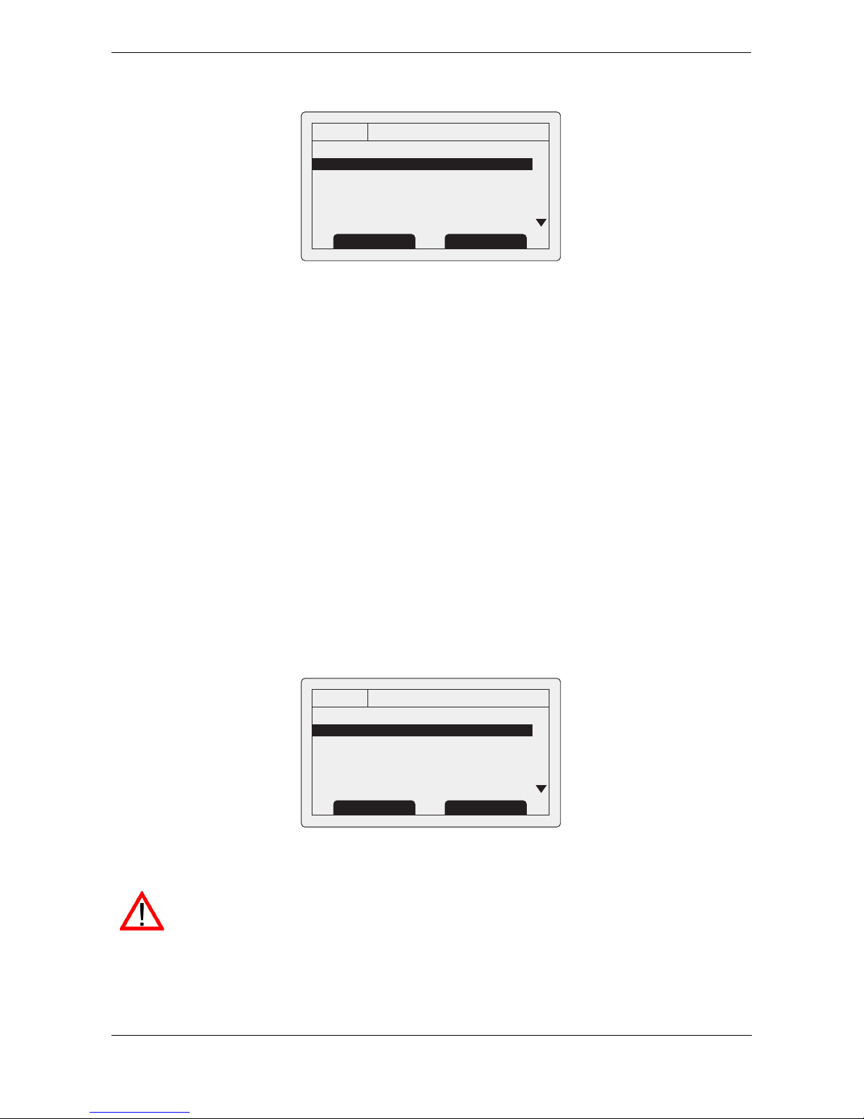
3.6 Own vessel and voyage data
This screen shows own vessel and voyage related data. This data relates to the vessel on which the transceiver
is installed.
Figure 6 Own vessel and voyage data screen
13:20:47
TARGET LIST:
NAME/MMSI RNG(NM) BRG(deg)
MARY ROSE 001.5 254.0
REGENT 003.0 013.0
ANNE GALLANT 012.5 135.5
235789543 015.0 003.0
456723557 030.0 087.5
OK
GPS
INT
ScreenSelect
13:20:47
VESSEL DETAILS:
Station type: Class A
MMSI: 235687901
Name:
>> MARY ROSE
Call Sign: MYR7A
IMO No: 4325640
OK
GPS
INT
Prev. vessel Next vessel
13:20:47
OWN VESSEL DATA:
MMSI: 375570700
Name:
>> POSEIDON
Call Sign: POS456
IMO No: 5678901
Destination: SOUTHAMPTON
OK
GPS
INT
Screen

Operation
Page 15
The information displayed on this screen includes:
● MMSI - the Maritime Mobile Service Identity for the vessel on which the transceiver is installed.
● Vessel name
● Call sign
● Destination - the current voyage destination
● IMO Number (where applicable)
● ETA - Estimated Time of Arrival at the voyage destination
● Draught
● Navigational status - At anchor, underway etc
● Dimensions for internal GNSS antenna
● Crew - number of crew on board
● Type of ship/cargo
The scroll wheel can be used to highlight an item of static or voyage data. To edit voyage or installation data see
the ‘Voyage data’ and ‘Installation’ menus in section
3.16 and also the installation information in section 4.
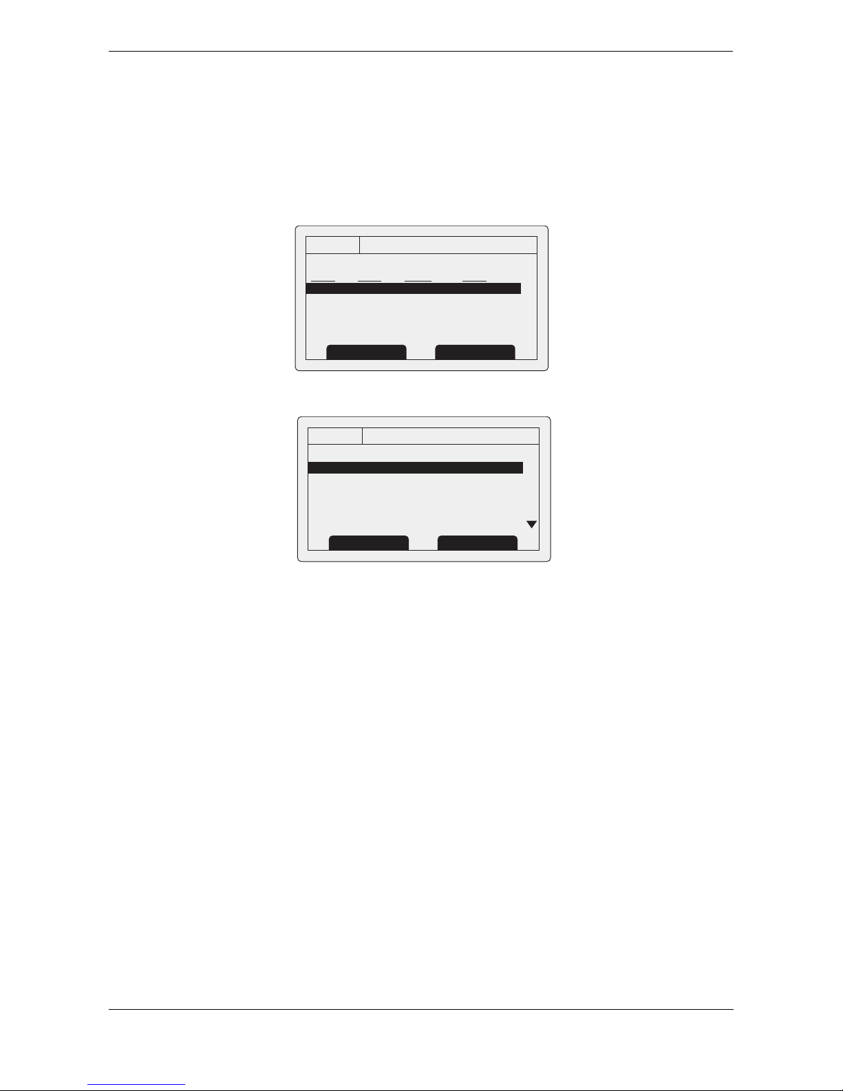
3.7 Own dynamic data
This screen shows current dynamic data from sensors connected to the transceiver and / or its built in GNSS
receiver. This is live information that is being periodically transmitted to other AIS equipped vessels.
The information displayed on this screen includes:
● Current date and time (UTC)
● Latitude
● Longitude
● SOG (Speed Over Ground)
● COG (Course Over Ground)
● Heading
● ROT (Rate Of Turn)
● Position accuracy
● RAIM status
● GNSS in use (internal or external)
Figure 7 Own dynamic data screen
13:20:47
OWN DYNAMIC DATA:
Date: 06/01/2010
Time: 13:24:04
Lat: 51°16.7904N
Long: 002°27.9458
SOG: 010.0kts
COG: 134.0°
OK
GPS
INT
Screen
Operation
Page 16
3.8 Received messages
This screen shows AIS text and Safety Related Messages (SRM) received from other AIS stations. The most
recently received message is shown at the top of the list. The date and time of reception, name or MMSI of the
sending station and type of message (text or SRM) are shown in the message list. To view the message content
select the required message using the scroll wheel, then either press the scroll wheel or the “View” function key.
The received messages screen is shown in Figure 8 and the message details screen in Figure 9. When unread
messages are available to view the message icon is shown in the status bar as described in section 3.3.1.
Figure 8 Received messages screen
Figure 9 Message details view
13:20:47
RECEIVED MESSAGES:
DATE TIME FROM TYPE
29/01 10:00 MARY R... BR Safety
29/01 09:55 556444321 AD Safety
28/01 21:45 REGENT B R Binary
OK
GPS
INT
View Screen
13:20:47
MESSAGE DETAILS:
Type: Broadcast SRM
MMSI: 235687901
NAME:
>>MARY ROSE
Channel: A
Date: 29/01/2010
OK
GPS
INT
Back Reply
Operation
Page 17
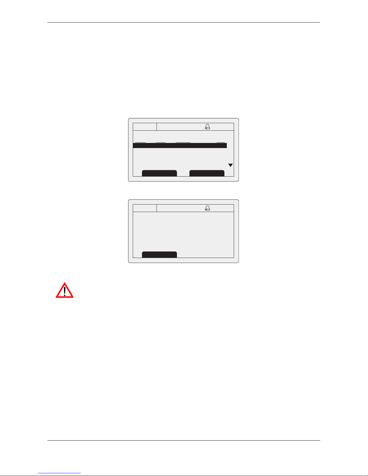
3.9 Alarms screen
This screen shows the status of AIS system alarms. If an active and not yet acknowledged alarm condition
exists the alarm icon in the status bar will flash. If an alarm condition occurs whilst not in the menu system an
acknowledgement screen will be shown immediately, this is described in section
3.12. If an alarm condition
occurs whilst editing a field in the menu system the alarm bell symbol flashes in the status bar.
The alarms screen shows the date and time of activation along with a brief description of any active alarm and
it’s acknowledge state — see
Figure 10. Alarms that are active but not acknowledged by the operator have ‘No’
in the ‘Ack’ column. Once an alarm is acknowledged by the operator ‘Yes’ is displayed in the ‘Ack’ column. An
individual alarm can be selected from the list using the scroll wheel and it’s details viewed by either pressing
the scroll wheel or the “View” function key. The alarm details view is shown in
Figure 11.
Figure 10 Alarms screen
Figure 11 Alarm details view
13:20:47
ALARMS LIST:
DATE TIME ALARM ACK
25/11 16:13 No valid ROT... Yes
25/11 16:11 Heading lost... Yes
25/11 16:11 External EPFS... Yes
OK
GPS
INT
View Screen
13:20:47
ALARM DETAILS:
ALARM: No valid ROT information
ID: 35
DATE: 25/11/2010
TIME: 16:13:30
ACK: Yes
OK
GPS
INT
Exit
While alarm conditions are active and un-acknowledged, any connected external alarm system
will remain activated.
Operation
Page 18
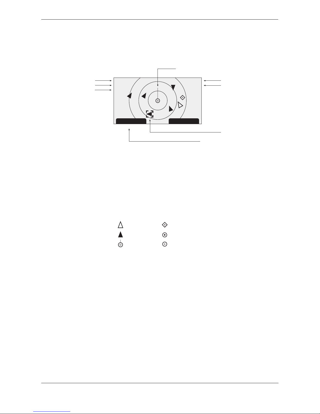
3.10 Target plot screen
The target plot screen shows the location of other AIS equipped vessels and shore stations relative to your own
vessel. The target plot screen provides a basic overview of AIS targets and should not be regarded as a
substitute for display of AIS information on a dedicated electronic chart display system (ECDIS).
Figure 12 Target plot screen
The plot range can be adjusted by pressing the ‘Range’ function key which cycles through the ranges 48, 24,
12, 6, 3, 1 and 0.5nm. The range relates to radius of the outer range ring shown on the screen.
Individual targets can be selected using the scroll wheel. When selected a square outline will appear around
the target, pressing the scroll wheel will display full vessel details. To return to the target plot screen from the
vessel details screen press the back key.
Different symbols are displayed for an AIS target depending on the type of target and its status, these are
shown in
Figure 13. The own vessel symbol is always shown at the centre of the plot.
Figure 13 Target plot symbols
3.11 Working with AIS text and Safety Related Messages (SRMs)
AIS text messages and Safety Related Messages (SRMs) can be received from other AIS equipped vessels
and also sent to specific vessels (addressed messages) or sent to all vessels in range (broadcast messages).
3.11.1 Receiving AIS text and Safety Related Messages
Reception of an AIS text message is indicated by the presence of the message icon in the status bar. This icon
is shown whenever there are unread AIS text messages. Messages can be reviewed and replied to via the
messages screen; see section
3.8.
When a Safety Related Message is received the user will be notified immediately with a screen showing the
message. Standard text messages are not displayed on receipt, however the message icon will be displayed
on the status bar.
Range Screen
Name of selected target MMSI of selected target
Heading line (points up to signify heading up)
Selected target
[HDG UP]
27 Tgts
10nm
MARY ROSE
235687901
Number of targets on display
Range selection key
heading up mode
Range selected
Lost target (vessel)
Target (vessel)
Own vessel
AtoN
Base station
SART
Operation
Page 19
Figure 14 Safety Related Message notification
3.11.2 Sending AIS Text and Safety Related Messages
To compose a new text or Safety Related Message (SRM) press the ‘Menu’ key then select the ‘MESSAGES’
sub menu followed by the ‘SEND A MESSAGE’ option. The new message screen is shown in
Figure 15. To
send a message complete the following steps:
1. Using the scroll wheel highlight the ‘TYPE’ field and select the type of message you wish to send. The
available options are ‘Broadcast text’, ‘Addressed Text’, ‘Broadcast SRM’ and ‘Addressed SRM’. Click
the scroll wheel to confirm the message type.
2. For addressed message types only select the ‘TO’ field and press the scroll wheel. Enter the MMSI of
the vessel the message should be sent to using the scroll wheel. See section
3.13 for instructions on
using the scroll wheel to enter data.
3. Select the ‘MESSAGE’ field and enter your message. Note that the length of a message is limited as
follows:
○ Addressed SRM 156 characters
○ Broadcast SRM 161 characters
○ Addressed text 151 characters
○ Broadcast text 156 characters
4. Press the ‘Send’ function key to transmit the message.
When an addressed message is sent the addressee will return an acknowledgement on receipt of the
message. If this acknowledgement is not received a warning will be displayed.
Figure 15 Message composition
Warning: Class B transceivers are permitted to receive broadcast Safety Related Messages and
broadcast text messages, however this function is not mandatory. Class B transceivers are not able
to receive addressed Safety Related or text messages. There is therefore no guarantee that text
messages or SRMs sent to a Class B transceiver will be received.
13:20:47
SAFETY RELATED MESSAGE:
Type: Broadcast SRM
MMSI: 235687901
NAME:
>>MARY ROSE
Channel: A
Date: 29/01/2010
OK
GPS
INT
Back Reply
13:20:47
NEW MESSAGE:
Type: Broadcast SRM
MMSI: Not required
Channel: Auto
Message:
OK
GPS
INT
Back/Send Edit

Operation
Page 20
3.12 Handling alarms
The Oceansat transceiver performs self checking functions continuously. If a self check fails an alarm will
occur. Possible alarm conditions are listed in
Table 2.
Table 2 Alarm conditions
A new alarm will be indicated by display of the alarm notification screen (see Figure 16). The alarm icon in the
status bar will flash whilst an alarm is active and not acknowledged by the user.
Figure 16 Alarm notification screen
Alarm condition Description
Transmitter malfunction This alarm can occur if there is a fault with the transmitter or if
the antenna VSWR exceeds allowable limits. The alarm will be
cleared if the transmitter recovers normal operation or the VSWR
measurement returns to an allowable value. If this alarm condi
-
tion persists contact your dealer or installer.
Antenna VSWR exceeds limit This alarm condition can occur if the VSWR (Voltage Standing
Wave Ratio) of the AIS antenna exceeds pre-defined limits. This
alarm is cleared if the VSWR returns to an allowable value. If this
alarm condition persists contact your dealer or installer.
Receiver channel x malfunction
This alarm occurs should the receiver hardware malfunction. The
receiver is identified by the value of x. If the receiver returns to
normal operation this alarm will be cleared. If this alarm condition
persists contact your dealer or installer.
External EPFS lost This alarm occurs if the position from the external Electronic
Position Fixing System (i.e. GNSS) is invalid or lost.
No sensor position in use This alarm occurs if the transceiver has no valid position informa-
tion from any connected sensor.
No valid COG information This alarm occurs if the transceiver has no valid Course Over
Ground information from any connected sensor.
No valid SOG information This alarm occurs if the transceiver has no valid Speed Over
Ground information from any connected sensor.
Heading lost or invalid This alarm occurs if the transceiver has no valid heading infor-
mation from any connected sensor, or if the heading is undefined.
No valid ROT information This alarm occurs if the transceiver has no Rate Of Turn informa-
tion from connected sensors or via internal calculation.
13:20:47
ALARM NOTIFICATION:
ID ALARM
35: No valid ROT information
32: Heading lost/invalid
25: External EPFS lost
OK
GPS
INT
Goto List Ack

Operation
Page 21
From the alarm notification screen you have the option to immediately acknowledge the alarm by pressing the
‘ACK’ function key, or to view the active alarms list by pressing the ‘Goto List’ function key. Once an alarm is
acknowledged it will remain in the alarms list whilst the underlying alarm condition is active. The presence of
active but acknowledged alarm conditions is indicated by continuous display of the alarm icon in the status bar.
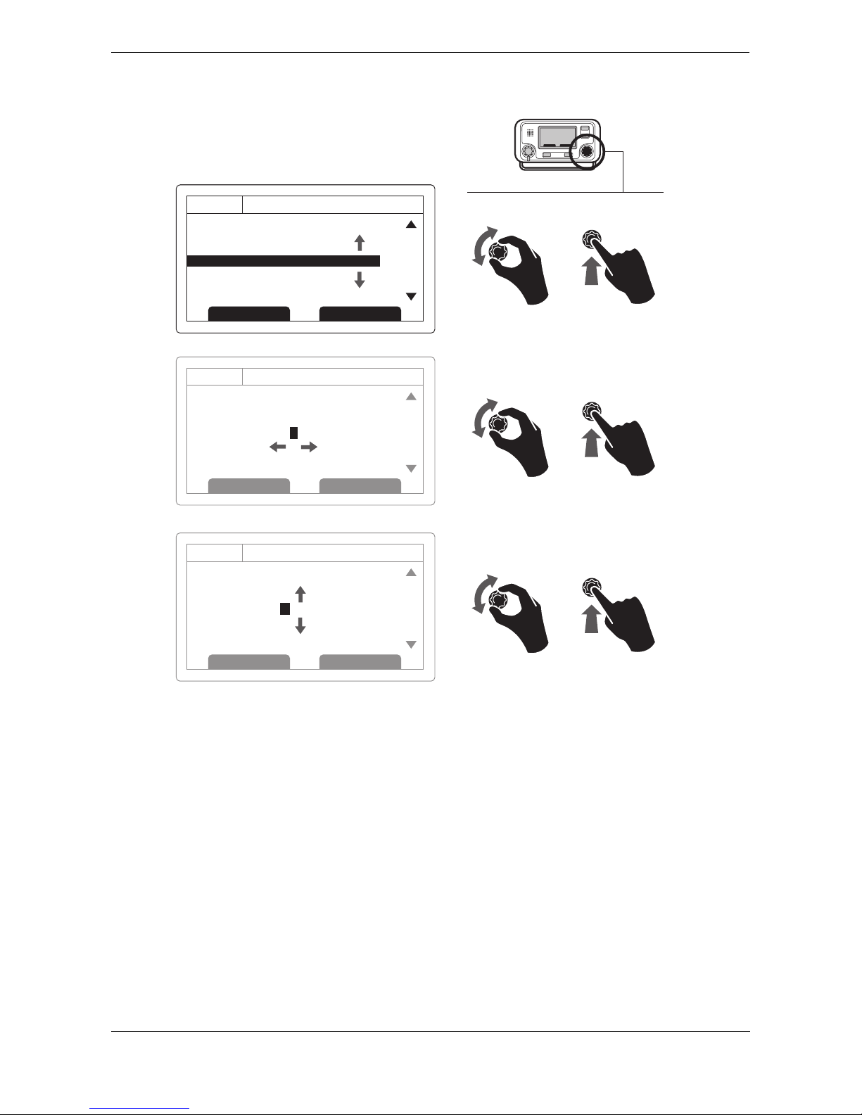
3.13 Entering text
The scroll wheel is used to enter text when updating settings or inputting new information. To enter or change
the text first select the field you wish to edit using the scroll wheel. The selected field is highlighted with white
text on a black background.
If the field is editable the ‘Edit’ function key will be shown. Either press this function key, or push the scroll wheel
to enter edit mode.
If text is already present in the field a solid block will now appear at the first character position, otherwise at the
first character position. Use the scroll wheel to move the block to the character position you wish to edit, then
press the scroll wheel. The selection will now flash, and rotating the scroll wheel will select the character for
this position. When the correct character is selected press the scroll wheel to fix the character and move to the
next character position. To ‘backspace’ (delete) a character simply press the ‘Back’ key.
Figure 17 explains the
text entry process.
When you have completed entering text press the ‘Save’ function key to save the updated information.
Operation
Page 22
Figure 17 Text entry
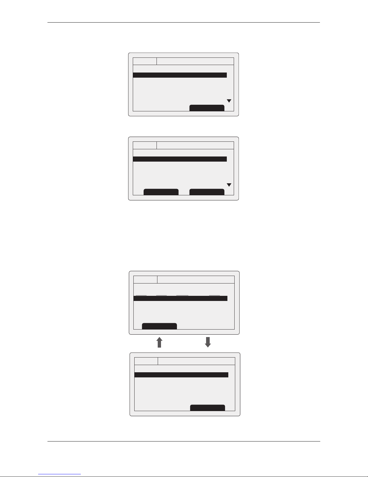
3.14 Long range messages
If the Oceansat transceiver is connected to a long range communication system via the long range
communications port then long range interrogations may be received. These are requests for information from
a distant base station beyond normal AIS operation range.
The Oceansat transceiver can be configured to automatically respond to Long range (LR) interrogations, or you
can opt to respond to any interrogation manually. Automatic response is the default setting, see section
3.16
for details of the menu option used to change this setting. Note that in automatic mode all requested information
is returned if it is available.
When a Long range interrogation is received you will be alerted by a notification screen as shown in Figure 18
(when automatic response is enabled) or Figure 19 (when manual response is enabled).
In automatic response mode simply review and acknowledge the notification screen using the ‘Acknowledge’
function key to return to the previous operating screen. In manual response mode you should review the
request and select either the ‘Respond’ or ‘Decline’ function key as appropriate.
10:05:20
Own static and voyage data:
MMSI: 123456789
NAME: POSEIDON
DESTINATION: SOUTH
ETA: 06/06/10 1400Hrs
OK
GPS
INT
Edit Screen
12
10:05:23
Own static and voyage data:
MMSI: 123456789
NAME: POSEIDON
DESTINATION: SOUT H
ETA: 06/06/10 1400Hrs
OK
GPS
INT
Cancel Save
10:05:25
Own static and voyage data:
MMSI: 123456789
NAME: POSEIDON
DESTINATION: SO U T H
ETA: 06/06/10 1400Hrs
OK
GPS
INT
Cancel Save
34
56
Q
R
S
T
U
V
W
Operation
Page 23
Figure 18 Long range interrogation notification; automatic response mode enabled
Figure 19 Long range interrogation notification; manual response mode enabled
A list of received Long range interrogation messages is available at any time via the main menu ‘Messages’
sub menu. See section
3.16 for more details. The Long range message list shows the time and date of
reception of each message along with the sending base station’s MMSI. Full details on each Long range
interrogation in the list can be viewed by pressing the ‘View’ function key. The Long range message list and
details views are shown in
Figure 20.
Figure 20 Long range message list and details views
13:20:47
Long range interrogation:
Date: 31/03/2010
Time: 13:15:39
MMSI: 001245368
OK
GPS
INT
Name:
>> RES
Response automatically sent
Acknowledge
13:20:47
Long range interrogation:
Date: 31/03/2010
Time: 13:15:39
MMSI: 001245368
OK
GPS
INT
Name:
>> RES
Set default responses
Respond
Decline
13:20:47
LONG RANGE MESSAGES:
DATE TIME FROM TYPE
08/01 15:52 002543887 Speed
08/01 15:30 002543887 Position
06/01 09:25 002564410 Course
OK
GPS
INT
View
13:20:47
MESSAGE DETAILS:
Date: 08/01/10
Time: 07:35:39
MMSI: 002543887
Response automatically sent
Name:
>> RES
OK
GPS
INT
Back Back
Operation
Page 24
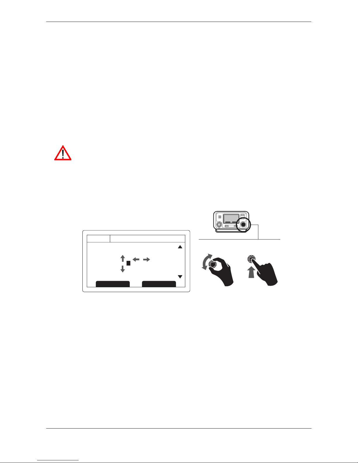
3.15 Passwords and security
Certain important information stored within the transceiver can not be changed without knowledge of the
password. The protected information includes:
● MMSI number
● Name of vessel
● Call sign
● IMO number
● Channel management settings
● Vessel dimensions and GNSS antenna locations
● Type of ship
● Data interface configuration
When trying to edit any of the above information you will be prompted to enter the password.
The password entry screen is shown in Figure 21. Use the scroll wheel to select the required digit, then push
the scroll wheel to edit the value of that digit. Entered password digits are masked by asterisks, when complete
press the scroll wheel to enter the password.
Figure 21 Password entry screen
3.16 The configuration menu
The transceiver configuration menu can be accessed at any time by pressing the ‘Menu’ key. The menu is
navigated by rotating the scroll wheel to select a sub-menu or menu item, and pressing the scroll wheel to
select that sub-menu or menu item. Pressing the ‘Back’ key will go back to the previous menu level, or exit the
menu system if you are currently viewing the top level menu.
Figure 23 shows the main menu screen.
You can return to the top level menu at any time by pressing the ‘Menu’ key, and exit the menu system at any
time by pressing and holding the ‘Back’ key for one second.
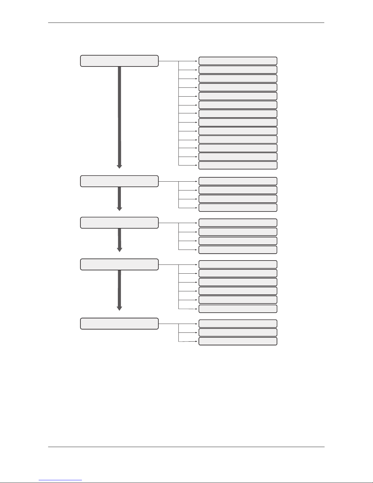
The main menu structure is shown in Figure 22. Some menu items are password protected and can only be
accessed using the password (see section 3.15).
Certain menu items are only available in Inland AIS mode. Please refer to section 3.17.
The default password is 00000000. The password may have been changed during installation.
For further information on changing the password refer to section .
10:05:21
ENTER PASSWORD:
0 . . . . . .
OK
GPS
INT
Edit Screen
12
8
9
A
B
C
Operation
Page 25
Figure 22 Main menu structure
VOYAGE DATA
NAVIGATIONAL STATUS
DESTINATION
ETA
DRAUGHT**
CARGO/SHIP TYPE**
NUMBER ON BOARD**
LOAD STATUS*
MESSAGES
NEW MESSAGE
MESSAGES INBOX
SENT MESSAGES
LONG RANGE MESSAGES
USER SETTINGS
KEY BEEP
DISPLAY
MAINTENANCE
SYSTEM INFORMATION
DIAGNOSTICS
SENSOR STATUS
INSTALLATION
SET IDENTIFICATION
DIMENSIONS
CHANGE PASSWORD
REGIONAL AREAS
SENSOR CONFIGURATION
INLAND AIS
LONG RANGE CONFIGURATION
STATIC DRAUGHT*
AIR DRAUGHT*
CREW*
PASSENGERS*
SHIPBOARD PERSONNEL*
ASSISTING TUG BOATS*
** Shown in ‘High Seas’ mode only
* Shown in ‘Inland AIS’ mode only
SET LANGUAGE
Operation
Page 26
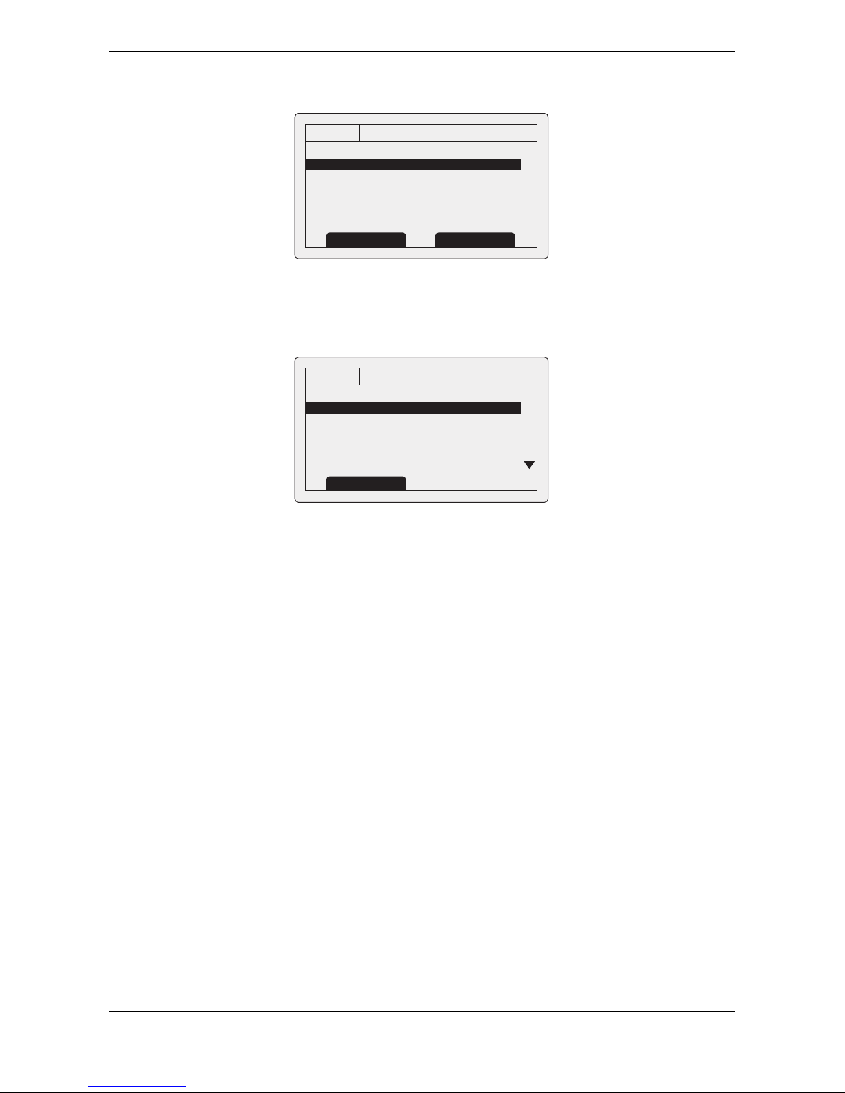
Figure 23 Main menu screen
3.16.1 Voyage data menu
The voyage data menu provides quick access to the most commonly changed AIS transceiver parameters.
Figure 24 The voyage data menu
From this menu you can set the following parameters:
● Navigational status - select the most appropriate navigational status for your vessel from the list.
○ Under way using engine
○ At anchor
○ Not under command
○ Restricted manoeuvrability
○ Constrained by her draught
○ Moored
○ Aground
○ Engaged in fishing
○ Under way sailing
○ Not defined (default)
● Destination - enter the destination for the current voyage, 20 characters maximum.
● ETA - enter the estimated time and date of arrival at the destination. The date format is DD/MM and
the time format HH:MM using a 24 hour clock and UTC time.
● Draught - enter the maximum present static draught for your vessel in metres. The format for this
value is xx.x m (e.g., 02.5m). The maximum draught is 25.5m, you should enter this value if your
draught exceeds 25.5m.
● Cargo/ship type - see section 4.5.3.
● Number on board - number of crew on board, up to 8191 maximum.
13:20:47
MAIN MENU:
VOYAGE DATA
MESSAGES
USER SETTINGS
INSTALLATION
MAINTENANCE
OK
GPS
INT
Back Select
13:20:47
VOYAGE DATA:
Nav Status:
>>(15) not defined (default)
Destination:
>>Not Available
ETA: --:--:-Draught: Not Available
OK
GPS
INT
Back
 Loading...