

OCEAN PRESENCE OPT-06SD/HD User Manual
OCEAN
PRESENCE
Technologies
Underwater IP Camera System
OPT-06SD/HD User’s Manual
Version 2.1
OceanCam
™
Models: OPT-06SD, OPT-06SDE, OPT-06HD, OPT-06HDE,
OPT-06FHD & OPT-06FHDE
Ocean Presence Technologies ©2011-2013 All Rights Reserved.

OceanCam User’s Manual Version: 1.0 7/16/13
Ocean Presence Technologies Copyright ©2011-2012 All Rights Reserved. Page 2
NOTICE TO USERS
Copyrights © 2010-2013 Ocean Presence Technologies.
All rights reserved.
This manual or the software described
herein, in whole or in part, may not be
reproduced, translated or reduced to any
machine-readable form without prior written
approval from Ocean Presence
Technologies.
OCEAN PRESENCE TECHNOLOGIES AND SONY
CORPORATION PROVIDES NO WARRANTY WITH
REGARD TO THIS MANUAL, THE SOFTWARE OR
OTHER INFORMATION CONTAINED HEREIN AND
HEREBY EXPRESSLY DISCLAIMS ANY IMPLIED
WARRANTIES OF MERCHANTABILITY OR
FITNESS FOR ANY PARTICULAR PURPOSE WITH
REGARD TO THIS MANUAL, THE SOFTWARE OR
SUCH OTHER INFORMATION. IN NO EVENT
SHALL OCEAN PRESENCE TECHNOLOGIES NOR
SONY CORPORATION BE LIABLE FOR ANY
INCIDENTAL, CONSEQUENTIAL OR SPECIAL
DAMAGES, WHETHER BASED ON TORT,
CONTRACT, OR OTHERWISE, ARISING OUT OF
OR IN CONNECTION WITH THIS MANUAL, THE
SOFTWARE OR OTHER INFORMATION
CONTAINED HEREIN OR THE USE THEREOF.
Ocean Presence Technologies reserves the right to
make any modification to this manual or the
information contained herein at any time without
notice.
The software described herein may also be governed
by the terms of a separate user license agreement.
• “UWIP,” “Underwater IP Camera”,
“OceanCam” and “OceamCam” are
trademarks of Ocean Presence
Technologies.
• “IPELA” is a trademark of Sony Corporation.
• Microsoft, Windows, Internet Explorer and
MS-DOS are registered trademarks of
Microsoft Corporation in the United States
and/or other countries.
• Java is a trademark of Sun Microsystems,
Inc. in the United States and other countries.
• Intel and Pentium are registered trademarks
of Intel Corporation or its subsidiaries in the
United States and other countries.
• Adobe, Acrobat and Adobe Reader are
trademarks of Adobe Systems Incorporated
in the United States and/ or other countries.
All other company and product names are trademarks
or registered trademarks of the respective companies
or their respective makers.
Indicates potential electrical
hazard. Please handle with care
and observe all proper operations
and warnings.
If you have any questions about this
product, you may call:
Ocean Presence Technologies at:
831-426-4678
or E-mail to: info@oceanpresence.com
or Write to:
Ocean Presence Technologies
326 Pacheco Ave.
Santa Cruz, CA 95062 USA

OceanCam User’s Manual Version: 1.0 7/16/13
Ocean Presence Technologies Copyright ©2011-2012 All Rights Reserved. Page 3
TABLE of CONTENT
1.0 SHIPPED COMPONENTS ..................... 4
2.0 QUICK START....................................... 4
2.1 Unpacking Instructions.......................... 4
2.2 Connecting the Camera ........................ 5
2.3 Configuring the Network ....................... 5
2.4 Deployment Testing.............................. 6
3.0 SYSTEM DESCRIPTION........................ 7
3.1 Hardware Assembly.............................. 7
3.2 Camera System .................................... 7
3.3 Housing ................................................ 8
3.4 Power & Network Subsystems .............. 8
3.5 Moisture Purging System...................... 9
3.6 Buoyancy Control ................................. 9
4.0 CAMERA OPERATIONS ..................... 10
4.1 Software Installation ........................... 10
4.2 Assigning IP Address.......................... 10
4.3 Configuring the Camera...................... 11
4.3.1 Video Settings........................ 11
4.3.2 Upright Mounting.................... 12
4.3.3 Home Position........................ 12
4.3.4 White Balance........................ 12
4.4 SNC Desktop Viewer .......................... 12
4.4.1 Area zoom ............................. 13
4.4.2 Vector dragging...................... 13
4.4.3 Panorama Control .................. 14
4.5 Recording Images & Video ................. 14
4.6 Media Player Software........................ 14
4.7 Free Plug-in Viewer ............................ 15
4.8 Operation Authority............................. 16
4.9 Position Presets & Tours..................... 16
4.10 Image Transmission ........................... 17
5.0 SYSTEM ACCESSORIES .................... 18
5.1 Underwater Lighting............................ 18
5.2 Hydrophone ........................................ 18
5.3 Wireless Network ................................ 19
5.4 Remote Power Systems...................... 19
5.5 Ethernet Extender ............................... 19
5.6 Smart Phone Viewer ........................... 19
6.0 PRE-DEPLOYMENT TESTING ............ 20
6.1 Camera/Network Tests ....................... 20
6.2 Final Check-out................................... 20
7.0 CARE & MAINTENANCE..................... 21
7.1 Opening the Housing .......................... 21
7.2 Closing the Housing............................ 21
7.3 Above Water Maintenance .................. 21
7.4 O-Ring Greasing Technique................ 22
7.5 Below Water Maintenance .................. 22
7.6 Periodic Maintenance.......................... 22
8.0 APPENDIX........................................... 23
8.1 Troubleshooting Guide........................ 23
8.1.1 Camera Power Light Off ......... 23
8.1.2 Camera Network Light Off ...... 23
8.1.3 Camera Not in SNC Toolbox... 23
8.1.4 DSN Error/Server Not Found .. 24
8.2 Dome Field Replacement.................... 24
8.2.1 Dome Removal....................... 24
8.2.2 Dome Installation.................... 24
8.3 Warranty ............................................. 26
8.4 Accessories (Optional) ........................ 26
8.5 Replacement Parts ............................. 26
8.6 Camera Specifications ........................ 27
8.6.1 System Requirements ............ 27
8.6.2 Camera Specifications............ 27
8.6.3 Camera Components ............. 28
8.7 Housing Specifications........................ 28
8.8 Mounting the Camera.......................... 29
8.9 Underwater Cable Wiring .................... 29
OceanCam User’s Manual Version: 2.0 7/16/13
Ocean Presence Technologies Copyright ©2011-2013 All Rights Reserved. Page 4
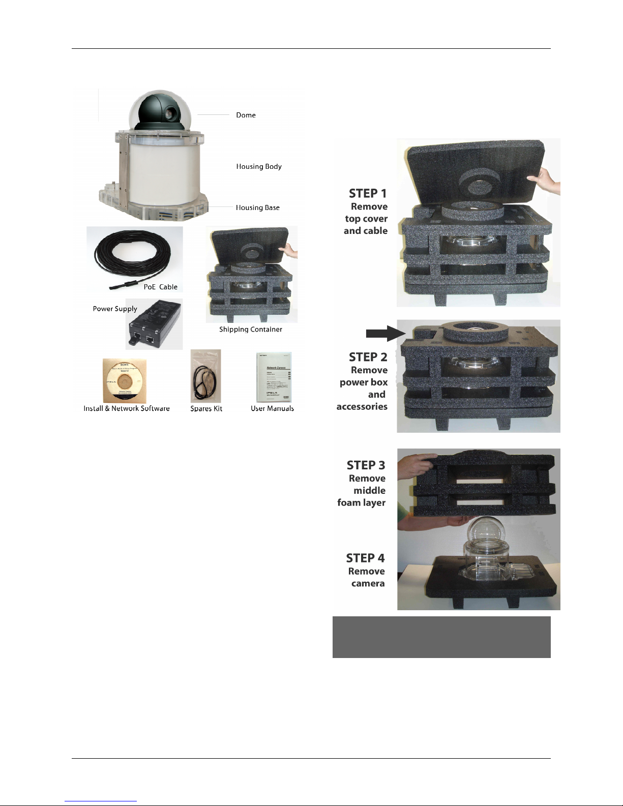
1.0 SHIPPED COMPONENTS
1) Underwater camera in housing,
2) Power-over-Ethernet (PoE) cable,
3) PoE power supply with power cord,
4) Software CD,
5) Spares kit: allen wrench, silicone
grease, silica bags and
6) Users manuals.
2.0 QUICK START
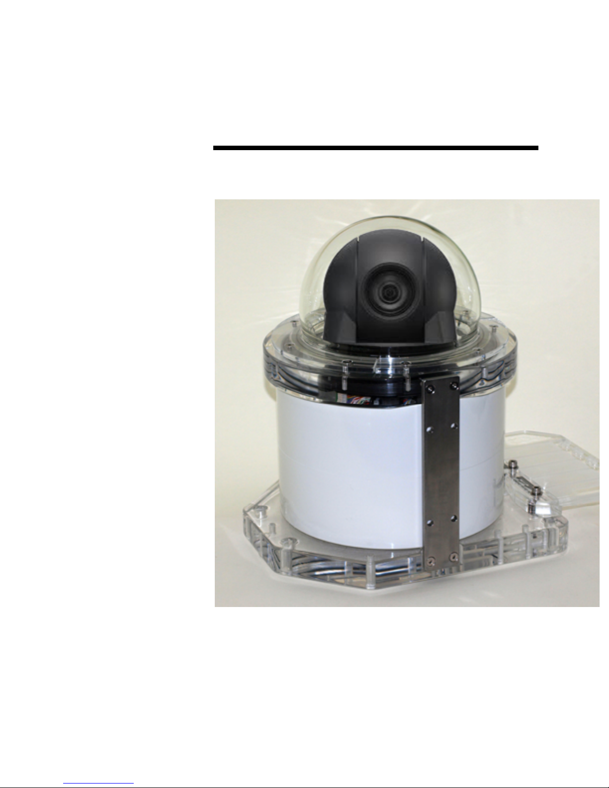
The OceanCam Underwater IP camera
system (UWIP) has been designed to
simplify installation and deployment. It
involves four simple steps:
1) Unpacking the camera
2) Connecting the camera
3) Configuring the network
4) Deployment testing
Step #4 is covered in detail in Section 6 of
this manual.
2.1 UNPACKING INSTRUCTIONS
The OceanCam is shipped in a specially
designed packing box. The camera is
packed with protective foam and is ready
to use out of the box.
THE BOX AND PACKING MATERIALS
SHOULD BE RETAINED IN THE EVENT THAT
SHIPPING IS REQUIRED
OceanCam User’s Manual Version: 2.0 7/16/13
Ocean Presence Technologies Copyright ©2011-2013 All Rights Reserved. Page 5
2.2 CONNECTING THE CAMERA
The OceanCam is ready to be used out of
the box. It employs a PTZ camera that is
network ready.
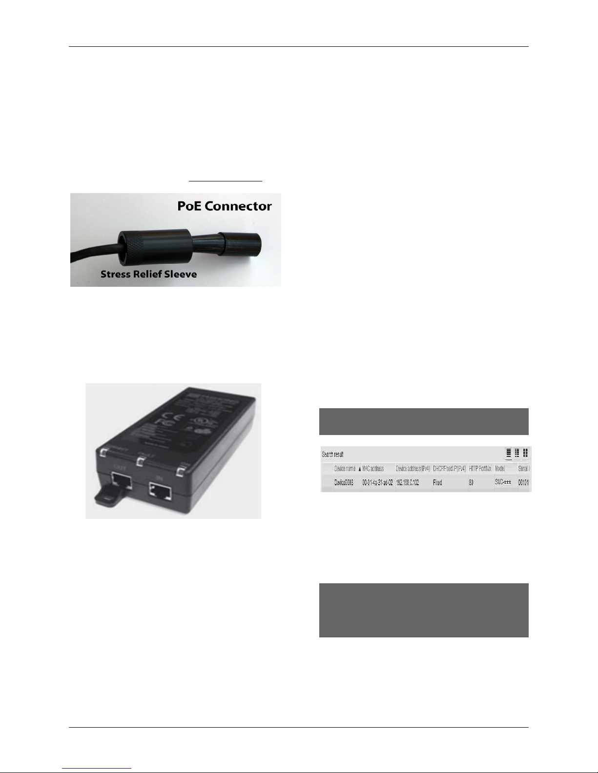
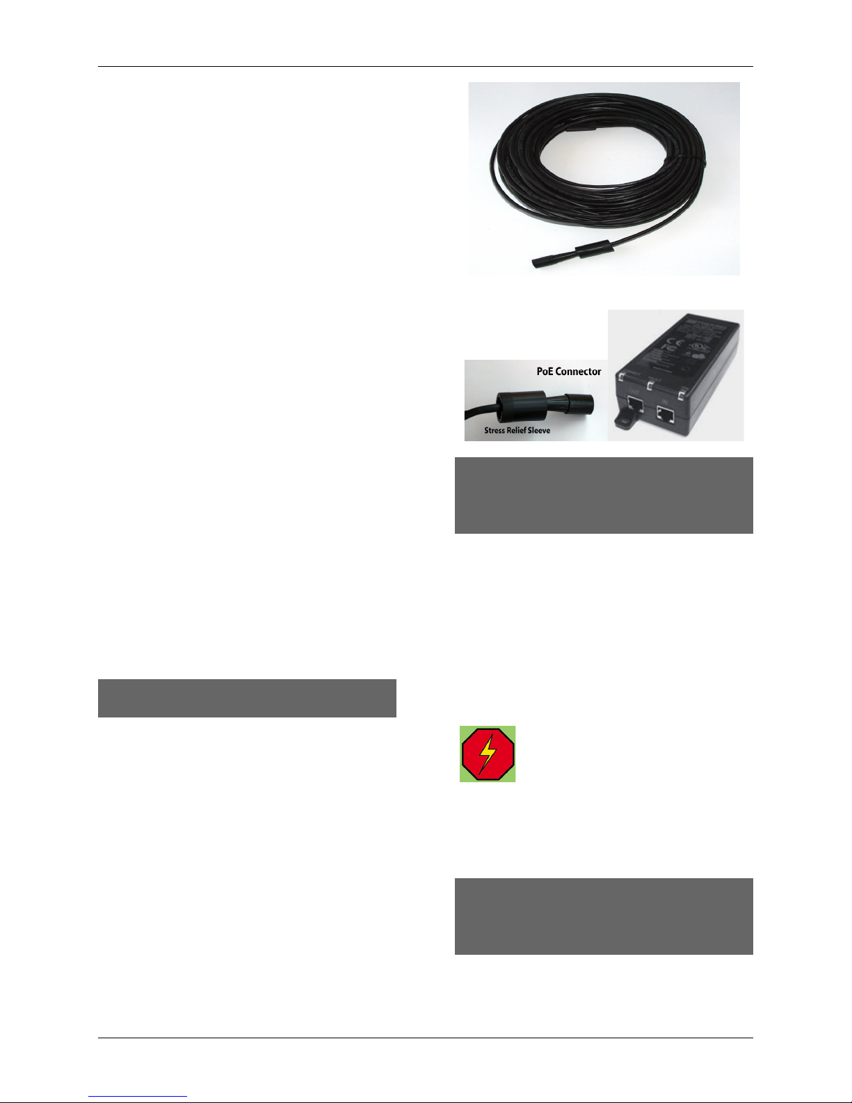
The standard system includes a power
supply and an underwater Power-overEthernet (PoE) cable. The PoE connector
should be attached to the housing and the
cable stress relief sleeve lightly tightened.
To connect to the network, attach the other
end of the PoE cable to the OUT port of
the power supply. A standard Ethernet
cable can then be attached from the IN
port of the power supply to a router,
computer or Internet modem.
A router can be used to initially configure
the camera. To connect directly to a
computer, a commercially available
network crossover cable or coupler (not
supplied) may be required.
Once all the network cables have been
attached, you can apply power to the
system.
The camera will initially blink both the
power and network lights. The power light
will stay on and the network light will blink
for two minutes at which time the turret will
realign to the home position.
The network light will illuminate, indicating
that the network connection was
successful. (If this network light is not
green or amber, see Section 8.1.2 for more
detailed instructions or troubleshooting
guide in Appendix A.
2.3 CONFIGURING THE NETWORK
The first time that you install the camera on
your computer you will need to download
the configuration software from the
Installation CD. Insert the CD in your CDROM drive. A cover page will appear. Click
the Setup icon of the SNC toolbox. The file
download dialog opens. Install the SNC
Toolbox into your Windows computer using
the wizard.
Start the SNC Toolbox and click “Search”
to detect the camera. The program will
detect any camera on the network. (See
included Sony User Manual for detailed
installation and operations.)
The camera will become visible on the
network as indicated by appearing in the
SNC Toolbox program.
THE FACTORY SETTING FOR THE CAMERA
IS SET TO DHCP.
Double-clicking on this camera will launch
the camera in a browser window. Only a
Windows operating system can be used to
administer the program, although other
operating systems can be used to view and
control the camera.
FIREFOX, SAFARI AND OTHER APPLE
BASED BROWSERS ARE SUPPORTED FOR
VIEWING AND CAMERA CONTROL.
RECORDING IS DONE USING ACTIVEX.
See Section 4.4 and Section 4.7 for details
on the operation of the two video viewers.

OceanCam User’s Manual Version: 2.0 7/16/13
Ocean Presence Technologies Copyright ©2011-2013 All Rights Reserved. Page 6
2.4 DEPLOYMENT TESTING
The camera can be deployed while the
network is operational. This will allow the
monitoring of any leakage.
DO NOT PLUG IN OR REMOVE THE
HOUSING POE CONNECTOR WHILE
UNDERWATER WHEN THE POWER
IS ON!
Weights can be added to adjust the
buoyancy. Attach 4-5 pound weights to
each corner of the housing using plastic
cable ties.
It is advisable to test the system in fresh
water prior to saltwater deployment. If this
is not possible, lower the camera into the
water with the camera pointing vertical and
the network active.
If a perfect o-ring seal has not been
obtained, fogging or condensation will soon
appear on the inside of the top of the
dome.
A submergence test can also we
performed without power applied. Lower
the system to a depth of 10 feet and then
remove it for visible inspection for leaks. If
possible, test the system again at a depth
of 30 feet for 15 minutes.
IF ANY MOISTURE IS SEEN ON THE
TOP OF THE DOME, REMOVE THE
SYSTEM FROM THE WATER
IMMEDIATELY!
If moisture is seen on the top inside of the
dome, either the O-ring was not properly
sealed or additional moisture removal may
be required. If a dry system cannot be
obtained, please contact the manufacturer
for assistance.
OceanCam User’s Manual Version: 2.0 7/16/13
Ocean Presence Technologies Copyright ©2011-2013 All Rights Reserved. Page 7
3.0 SYSTEM DESCRIPTION
3.1 HARDWARE ASSEMBLY
The camera system is shipped completely
assembled and ready for operation.
Attach the PoE cable to the camera using
the underwater connector. Lightly tighten
the stress relief sleeve. Additional plastic
cable ties can also be used.
Attach the other end of the PoE cable to
the power injector. An optional waterproof
power/wireless box may have already been
wired to the PoE cable.
Attach the Ethernet cable to the network
consisting of a router, wireless network
adapter, computer or direct Internet
modem.
Connecting to a computer may require a
crossover cable (not supplied).
Once both network connectors are
attached, plug the power into a 110/240
VAC source. Once power is supplied to the
camera, it will “boot” and move to the
“home” position.
The system provides for the removal of
moisture from inside the housing with the
use of silica bags. The housing exerts
approximately 10-16 pounds of positive
buoyancy. Weights can be attached to
either side of the housing.
Once all the network cables have been
attached, you can apply power to the
system.
The camera will initially blink both the
power and network lights. The power light
will stay on and the network light will blink
for two minutes at which time the turret will
realign to the home position.
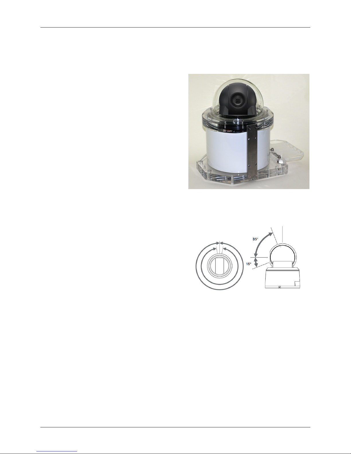
3.2 CAMERA SYSTEM
The OceanCam employs a PTZ (pan-tiltzoom) camera that has been designed for
24x7 operations.
The camera has a rotation range of 340degress or 360-degrees endless rotation
(depending on model) and can tilt 210degrees with an auto-flip feature that keeps
the image properly oriented.
Both optical and digital zoom is available
although, digital zoom is generally disabled
to obtain the sharpest underwater images.
OceanCam User’s Manual Version: 2.0 7/16/13
Ocean Presence Technologies Copyright ©2011-2013 All Rights Reserved. Page 8
3.3 HOUSING
The OceanCam housing has been
specially designed and manufactured for
select IP cameras. Model OPT-06 has
been designed for a maximum working
depth of 180 feet. Other models are
available for greater working depths.
The housing uses a specially designed
greater than hemi-sphere glass dome that
allows for greater clarity and a harder
surface capable of being cleaned
underwater. A nylon sponge can be used
on the glass dome only as other surfaces
maybe scratched.
The housing features cable stress relief.
The housing uses pairs of circular o-rings
to insure a more reliable seal. The cylinder
is free of attached components and can be
completely removed exposing the camera
and components.
The housing has been specially designed
to protect the electronics from small
amounts of water in the unlikely event of
an improperly seated o-ring.
NOTE: When underwater lighting (Section
5.1 or hydrophone (Section 5.2) is not
being used, plugs with o-rings may be
supplied. These have been tightened in the
factory and should not need any attention.
HAND TIGHTEN PLUGS ONLY!
DO NOT FLATTEN THE O-RING.
3.4 POWER & NETWORK SUBSYSTEMS
Power-over-Ethernet (PoE) has the ability
to carry both data and power over a single
Cat5 cable. The underwater PoE connector
can be attached or removed underwater. A
stress relief sleeve is also used.
DO NOT OVER TIGHTEN THE CAP AS THE
BULKHEAD MAY BE LOOSEN UPON
REMOVAL OF THE CAP. THIS MAY CAUSE
LEAKING!
The system may employ a PoE power
supply (PoE injector). A standard Ethernet
Cat5 network cable connects to a local
area network (router) and then to the
Internet. For testing purposes, a F-F
connector and crossover cable may be
needed when connecting directly to a
computer without going through a network
router.
A 110/240 VAC power supply is
used to deliver 48 VDC to the
camera through the PoE cable.
A power converter/regulator inside the
camera converts to 12 VDC used by the
camera. The camera can also be powered
from 48 VDC batteries.
DO NOT PLUG IN OR REMOVE THE
HOUSING POE CONNECTOR WHILE
UNDERWATER WHEN THE POWER
IS ON!
OceanCam User’s Manual Version: 2.0 7/16/13
Ocean Presence Technologies Copyright ©2011-2013 All Rights Reserved. Page 9
3.5 MOISTURE PURGING SYSTEM
To ensure the best operation of the
camera, moisture inside the housing needs
to be removed. This is done through the
use of silica drying bags. Bags only need
to be replaced if the housing is opened.
They can be regenerated in a warm oven.
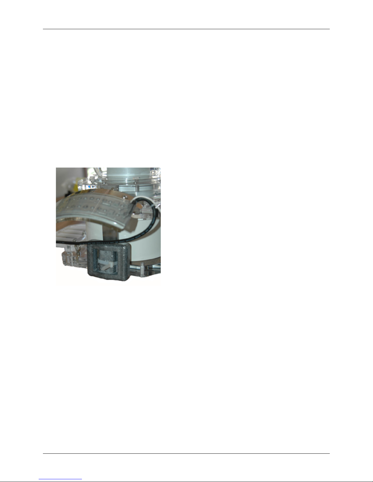
3.6 BUOYANCY CONTROL
Standard dive weights can be attached to
each side of the housing for buoyancy
control. The amount of weight is based on
the surge conditions of each deployment.
Weights should not be used for permanent
placement or in very high surge.
Weights should not be used for permanent
placement or in high surge. Standard lead
dive weights can be used instead of the
weight tray. Attach weights to the metal
bars on either side of the housing.
 Loading...