

Page 1
Breakout Box
Installation and Operation Instructions
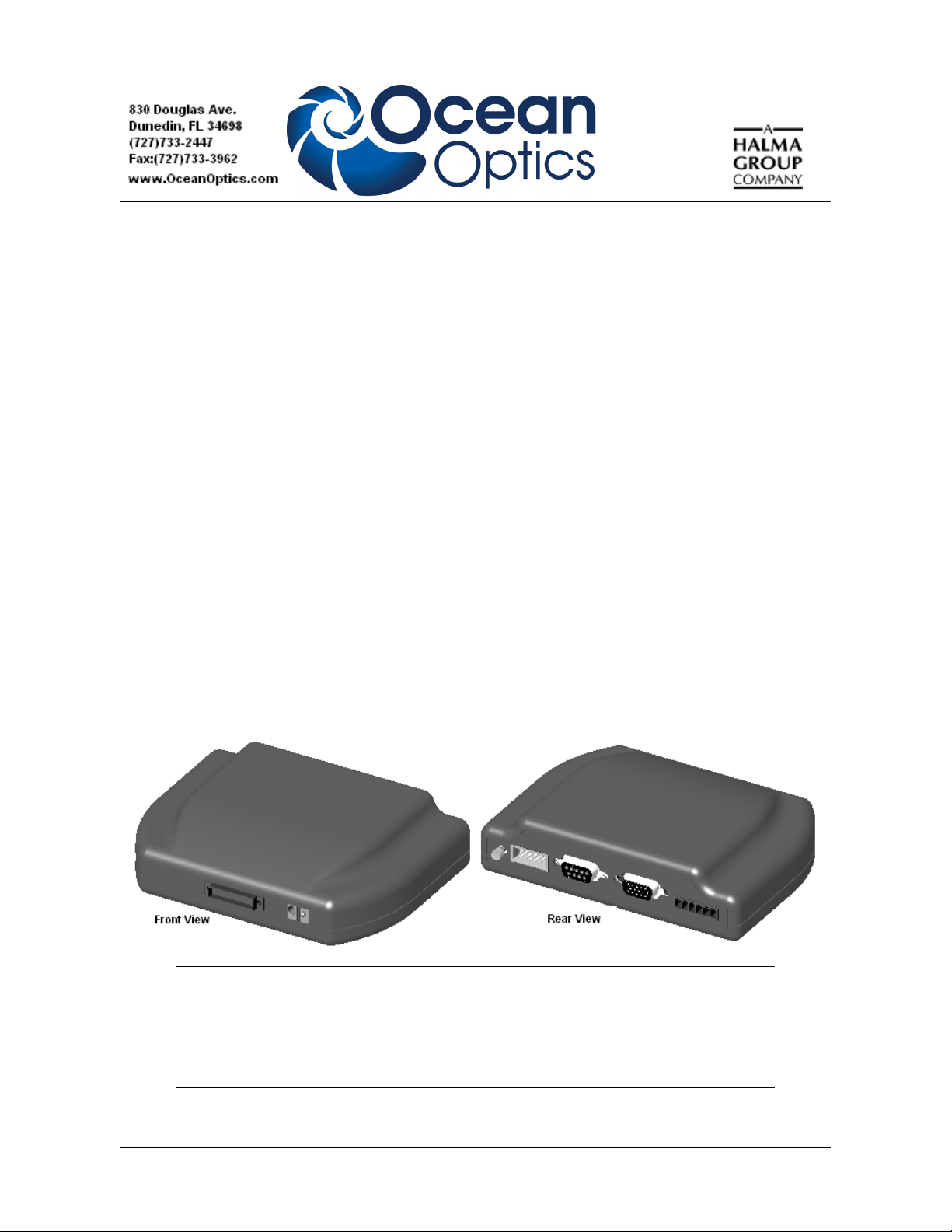
Description
The Ocean Optics Breakout Box (HR4-BREAKOUT) is a passive module that separates the signals
from their 30-pin port to an array of standard connectors and headers, enabling easy access to a variety
of features found in Ocean Optics’ HR2000+, HR4000, USB4000 (with USB-ADP-BB adapter), and
QE65000 Spectrometers. In addition to the accessory connector, the breakout box features a circuit
board based on a neutral breadboard pattern that allows custom circuitry to be prototyped on the board
itself.
The Breakout Box allows multiple interfaces to the spectrometer, such as the following:
• DB-15 light sources
• RS-232 interface
• GPIO
• External triggering
• Analog Input/Output
Note
The Breakout Box is compatible with HR4000 Spectrometers with Revision B or
greater. HR4000 Spectrometers with serial numbers beginning with HR4A are not
compatible with the HR4000 Breakout Box.
212-00000-000-01-1108 1
Page 2
HR4-BREAKOUT Installation and Operation Instructions
Parts Included
The Ocean Optics HR4000 Breakout Box ships with the following items:
• Breakout Box (HR4-BREAKOUT)
• Breakout Box Accessory Cable (HR4000-CBL-BB) - A 1-foot, 30-pin ribbon cable that
connects the spectrometer to the breakout box.
Connecting the Breakout Box
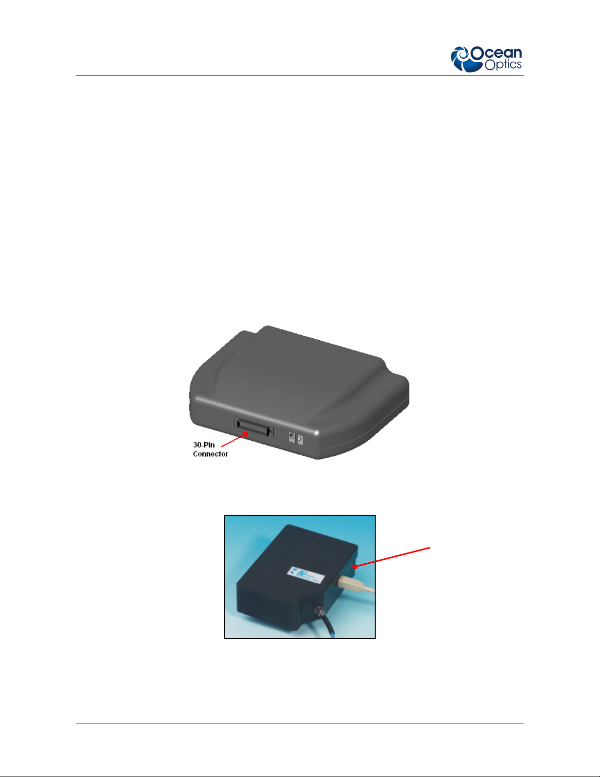
► Procedure
Follow the steps below to connect the breakout box to the spectrometer:
1. Connect the accessory cable to the 30-pin connector on the front of the breakout box. The
HR4000-CBL-BB cable is polarized so that only fits in the breakout box and spectrometer
connectors one way.
Breakout Box (Front View)
2. Connect the other end of the cable to the spectrometer.
30-Pin Connector
Spectrometer Connection
2 212-00000-000-01-1108
Page 3
HR4-BREAKOUT Installation and Operation Instructions
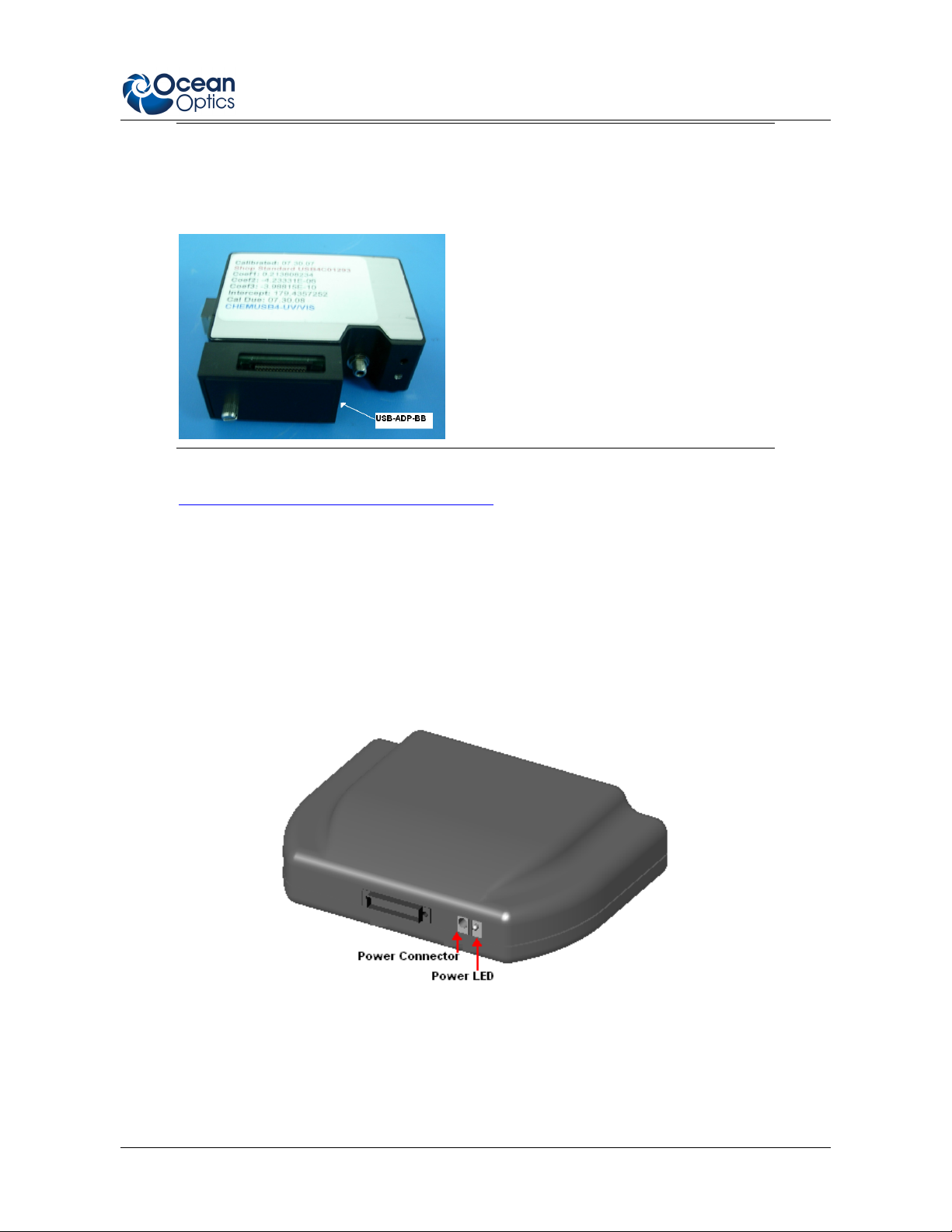
Note
If you are connecting the Breakout Box to the USB4000 Spectrometer, you must first
install the USB-ADP-BB adapter on the spectrometer as shown:
3. Connect the desired device to the appropriate pins on the Breakout Box’s circuit board (see
Circuit Board Connectors Pinout Information).
Supplying Power to the Breakout Box
The Breakout Box can be powered by
• The spectrometer via its USB port, or
• A separate 5V power supply (ADC-USB-SER). This power supply and serial cable must be
purchased separately. If you are wiring custom circuitry on the Breakout Box, you must use
the 5V power supply.
212-00000-000-01-1108 3
Page 4

HR4-BREAKOUT Installation and Operation Instructions
Accessing the Connectors on the Circuit Board
To access the connectors on the circuit board inside the breakout box, remove the four screws on the
bottom of the breakout box using a Phillips-head screwdriver.
Breakout Box (Bottom View)
Breakout Box Specifications
30-Pin Connector Pinout Information
When facing the 30-pin connector on the front of the Breakout Box, pin numbering is as follows:
29 27 25 23 21 19 17 15 13 11 9 7 5 3 1
30 28 26 24 22 20 18 16 14 12 10 8 6 4 2
30-Pin Connector Pinout Diagram
Power LED
4 212-00000-000-01-1108
Page 5

HR4-BREAKOUT Installation and Operation Instructions
Table 1: 30-Pin Connector Pinout Information
Pin # Function Input/Output Description
1 RS232 Rx Input
2 RS232 Tx Output
3 GPIO (2) Input/Output
RS232 receive signal – Communicates with a PC over DB9
Pin 3
RS232 transmit signal – Communicates with a PC over DB9
Pin 2
General purpose software-programmable, digital
input/output (channel number)
4 V5_SW Output Regulated 5 Volt power pin – Supplies 50 mA (maximum)
5 Ground Input/Output Ground
6 I2C SCL Input/Output I2C clock signal for communication to other I2C peripherals
7 GPIO (0) Input/Output
General purpose software-programmable, digital
input/output (channel number)
8 I2C SDA Input/Output I2C data signal for communication to other I2C peripherals
9 GPIO (1) Input/Output
10
Ext. Trigger
In
Input
11 GPIO (3) Input/Output
12 V
USB
Input or
Output
General purpose software-programmable, digital
input/output (channel number)
TTL input trigger signal – See External Triggering Options
document for more information
General purpose software-programmable, digital
input/output (channel number)
Input power pin for spectrometer – When operating via USB,
this pin can power other peripherals – Ensure that
peripherals comply with USB specifications
13 SPI Data Out Output
14 V
USB
Input or
Output
SPI Master Out Slave In (MOSI) signal for communication to
other SPI peripherals
Input power pin for spectrometer – When operating via USB,
this pin can power other peripherals – Ensure that
peripherals comply with USB specifications
Table 1: 30-Pin Connector Pinout Information (Continued)
Pin # Function Input/Output Description
15 SPI Data In Input
16 GPIO (4) Input /Output
17 Single Strobe Output
18 GPIO (5) Input/Output
212-00000-000-01-1108 5
SPI Master In Slave Out (MISO) signal for communication to
other SPI peripherals
General purpose software-programmable, digital
input/output (channel number)
TTL output pulse used as a strobe signal – Has a
programmable delay relative to the beginning of the
spectrometer integration period
General purpose software-programmable, digital
input/output (channel number)
Page 6

HR4-BREAKOUT Installation and Operation Instructions
Pin # Function Input/Output Description
19 SPI Clock Output SPI clock signal for communication to other SPI peripherals
20
21
22 GPIO (6) Input/Output
23
24
25 Lamp Enable Output
26 GPIO (7) Input/Output
27 Ground Input/Output Ground
28 GPIO (8) Input/Output
29 Ground Input/Output Ground
30 GPIO (9) Input/Output
Continuous
Strobe
SPI Chip
Select
Analog In
(0–5V)
Analog Out
(0–5V)
Output
Output
Input 13-bit low power, analog-to-digital input with a 0–5V range
Output 9-bit programmable output voltage with a 0–5V range
TTL output signal used to pulse a strobe – Divided down
from the master clock signal
SPI Chip/Device Select signal for communication to other
SPI peripherals
General purpose software-programmable, digital
input/output (channel number)
TTL signal driven Active HIGH when the Lamp Enable
command is sent to the spectrometer
General purpose software-programmable, digital
input/output (channel number)
General purpose software-programmable, digital
input/output (channel number)
General purpose software-programmable, digital
input/output (channel number)
Circuit Board Connectors Pinout Information
The following tables list pinout information for the J2, J3, J4, J5, J6, and J7 connectors on the
breakout box circuit board.
6 212-00000-000-01-1108
Page 7

HR4-BREAKOUT Installation and Operation Instructions
J2 Connector Pinouts
Use the J2 connector for light source accessory connection.
Pin # Description Pin # Description
J2-1 Single_strobe J2-9 GPIO-9
J2-2 ContStrobe J2-10 GND_SIGNAL
J2-3 V5_SW J2-11 SDA
J2-4 ExtTrigIn J2-12 SCL
J2-5 ExtTrigIn J2-13 LampEnable
J2-6 GPIO-8 J2-14 A_IN
J2-7 A_OUT J2-15 GPIO-7
J2-8 ExtTrigIn
J3 Connector Pinouts
Use the J3 connector for GPIO connection.
Pin # Description Pin # Description
J3-1 GPIO-0 J3-6 GPIO-5
J3-2 GPIO-1 J3-7 GPIO-6
J3-3 GPIO-2 J3-8 GPIO-7
J3-4 GPIO-3 J3-9 GPIO-8
J3-5 GPIO-4 J3-10 GPIO-9
J4 Connector Pinouts
Use the J4 connector for RS-232 connection.
Pin # Description Pin # Description
J4-1 No Connection J4-6 No Connection
J4-2 Tx J4-7 No Connection
J4-3 Rx J4-8 No Connection
J4-4 No Connection J4-9 No Connection
J4-5 GND_SIGNAL
212-00000-000-01-1108 7
Page 8

HR4-BREAKOUT Installation and Operation Instructions
J5 Connector Pinouts
Use the J5 connector for internal breakout for custom circuitry.
Pin # Description Pin # Description
J5-1 Tx J5-9 VUSB
J5-2 Rx J5-10 GND_SIGNAL
J5-3 SCL J5-11 A_OUT
J5-4 SDA J5-12 A_IN
J5-5 MOSI J5-13 No Connection
J5-6 MISO J5-14 No Connection
J5-7 SPI_CLK J5-15 No Connection
J5-8 SPICS_OUT J5-16 No Connection
J6 Connector Pinouts
Use the J6 connector for internal breakout for custom circuitry.
Pin # Description Pin # Description
J6-1 GPIO-0 J6-9 GPIO-8
J6-2 GPIO-1 J6-10 GPIO-9
J6-3 GPIO-2 J6-11 VUSB
J6-4 GPIO-3 J6-12 GND_SIGNAL
J6-5 GPIO-4 J6-13 Single_strobe
J6-6 GPIO-5 J6-14 ContStrobe
J6-7 GPIO-6 J6-15 LampEnable
J6-8 GPIO-7 J6-16 ExtTrigIn
J7 Connector Pinouts
Use the J7 connector for analog input/output connection.
Pin # Description
J7-1 VUSB
J7-2 ExtTrigIn
J7-3 GND_SIGNAL
J7-4 A_OUT
J7-5 GND_SIGNAL
J7-6 A_IN
8 212-00000-000-01-1108
Page 9

HR4-BREAKOUT Installation and Operation Instructions
Mechanical Diagrams
212-00000-000-01-1108 9
Page 10

HR4-BREAKOUT Installation and Operation Instructions
10 212-00000-000-01-1108
 Loading...