

Oceanic Systems NMEA2000 3420 User Manual
NMEA2000® AC MONITOR
Part Numbers: 3420
USER MANUAL
Revision 2.00


1 Introduction ....................................................... 2
1.1 Product Features .............................................. 2
2 Installation ......................................................... 3
2.1 Unpacking the box ............................................3
2.2 Mounting the unit .............................................3
2.3 Connecting the NMEA2000® Cable ......................3
2.4 Connecting the sensor cables to the WAGO socket.4
2.5 AC Monitor Connections .....................................5
3 Conguration ......................................................6
3.1 Conguring Circuit Type .................................... 6
3.2 Device Instance ................................................9
4 Warranty ...........................................................11
5 Technical Support ..............................................12
1 of 12

INTRODUCTION
1
The Oceanic Systems NMEA2000® 3420 AC Monitor is designed to monitor any AC source
including single-phase (phase A), single-phase (phase A,B), and three-phase (phase A,B,C)
This unit is designed to operate in a protected marine environment such as an engine room. It is
very important that it is installed and set up correctly according to this manual. Please read and
follow the installation and setup instructions carefully to achieve the best results.
1.2 PRODUCT FEATURES
The NMEA2000® 3420 AC Monitor has the following features:
● Inputs from AC voltage (Max 280 VAC), 200 Amp AC Current
Transformer
● User Settable Device Instance using rotary switches
● User Settable Circuit Type
● Heartbeat blue LED conrming NMEA transmission.
● NMEA2000® micro C interface plug
● Panel or DIN rail mounting option
● The unit reports AC Voltage, Current, Power, Frequency.
2 of 12
INSTALLATION
2
2.1 UNPACKING THE BOX
You should nd the following items in the 3420 shipping box:
1 x 3420 NMEA2000® AC Monitor
1 x 3420 User Manual (This document)
1 x 3420 200 Amp AC Current Transformer
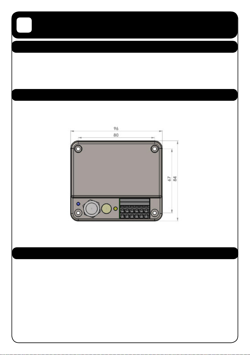
2.2 MOUNTING THE UNIT
The unit should be mounted to a at surface using 4 mounting screws. The unit dimensions and
mounting hole locations are shown on the following drawing.
Note: Mount away from sources of condensation and moisture
2.3 CONNECTING THE NMEA2000® CABLE
The unit is connected to the NMEA2000® network by the 5 way micro C socket on the front.
Carefully attach the network drop cable to this plug and hand tighten until it it is fully seated.
Take care to match the orientation of the pip inside the socket to the recess inside the drop
cable plug. The other end of the drop cable should be connected to a suitable Tee connector on
the NMEA2000® network backbone cable.
3 of 12
 Loading...