

Oceanic Systems NMEA2000 3410 User Manual
NMEA2000® DC MONITOR
Part Numbers: 3410
USER MANUAL
Document revision 2.00


1. Introduction................................................. 2
1.1 Product Features........................................... 2
2. Installation.................................................. 3
2.1 Unpacking the box........................................ 3
2.2 Mounting the unit.......................................... 3
2.3 Connecting the NMEA2000 Cable......................... 3
2.4 Connecting the sensor cables to the WAGO socket. 4
3. Calibrating the DC Current Transformer & Shunt... 6
4. Conguration.................................................... 7
4.1 Device Instance................................................. 7
4.2 Battery Type..................................................... 7
4.3 Nominal Voltage................................................ 7
4.4 Equalisation...................................................... 7
4.5 Calibrate to full battery.................................... 7
4.6 Peuker t Exponent.............................................. 7
4.7 Charge Efciency Factor..................................... 8
4.8 Battery Capacity............................................ 8
5. State of Charge Resetting................................... 9
6. Maintenance..................................................... 10
7. Technical Specication....................................... 11
8. Warranty.......................................................... 13
9. Technical Support ............................................ 14
1 of 14

INTRODUCTION
1
The Oceanic Systems NMEA2000® 3410 DC Monitor is designed to monitor any DC source
including batteries, PV Cells or Wind Generators on the NMEA2000® network.
This unit is designed to operate in a protected marine environment such as an engine room. It is
very important that it is installed and set up correctly according to this manual. Please read and
follow the installation and setup instructions carefully to achieve the best results.
1.2 PRODUCT FEATURES
The NMEA2000® 3410 DC Monitor has the following features:
● Inputs from battery voltage, 200 Amp DC Current Transformer,500 Amp
50mV Shunt, 1200 Amp 50mV Shunt
● User Settable Device Instance using rotary switch
● Heartbeat blue LED conrming NMEA transmission.
● NMEA2000 micro C interface plug
● Panel or DIN rail mounting option
The unit reports DC Voltage, DC Current and state of charge. It uses Peukart’s Constant and the
Charge Efciency Factor for the battery to ensure the most accurate state of charge reporting.
2 of 14
INSTALLATION
2
2.1 UNPACKING THE BOX
You will nd the following items in the 3410 shipping box:
1 x 3410 NMEA2000® DC Monitor
1 x 3410 User Manual (This document)
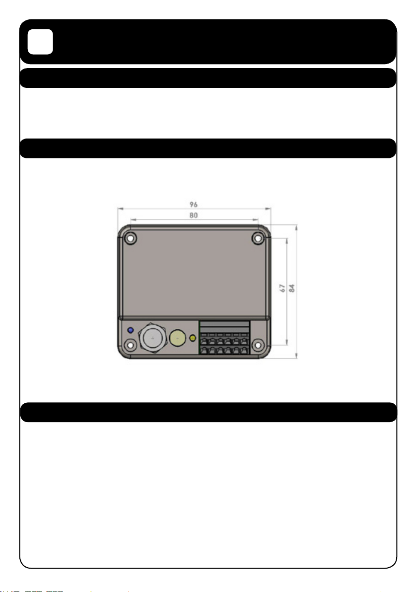
2.2 MOUNTING THE UNIT
The unit should be mounted to a at surface using 4 mounting screws. The unit dimensions and
mounting hole locations are shown on the following drawing.
Note: Mount away from sources of condensation and moisture
2.3 CONNECTING THE NMEA2000 CABLE
The unit is connected to the NMEA2000 network by the 5 way micro C socket on the front.
Carefully attach the network drop cable to this plug and hand tighten until it it is fully seated.
Take care to match the orientation of the pip inside the socket to the recess inside the drop
cable plug. The other end of the drop cable should be connected to a suitable Tee connector on
the NMEA2000 network backbone cable.
3 of 14
 Loading...