


OCEANIC SYSTEMS NMEA2000®
AC MODBUS GATWAY
Part Numbers: 3155
USER MANUAL
Document revision 1.21

1 of 59
1 Introduction ........................................................3
1.1 Product Features................................................3
2 Installation...........................................................4
2.1 Unpacking the box..............................................4
2.2 Choosing the mounting location...........................4
2.3 Mounting the unit...............................................4
2.4 Connecting the RS485 Modbus Interface................5
2.5 Connecting the NMEA2000® Interface...................5
3 Conguration........................................................6
3.1 Modbus Communication Parameters.......................6
3.2 Modbus Slave Address..........................................7
3.3 Modbus Termination Resistor................................7
3.4 NMEA Device Instance..........................................7
3.5 The Device Setup Process.....................................7
4 Front Panel Indicators and Switches.........................8
5 Fault Finding / Troubleshooting................................9
5.1 Communications error LEDs..................................9
5.2 Invalid Modbus Message Error Led..........................9
5.3 Unmarked LED – PGN became Data Not Available.....9
6 Data Naming Convention........................................10
7 Engine Instance 0 Registers....................................11
7.1 Engine Instance 0 Registers ................................12
7.2 Engine Instance 1 Registers ................................14
7.3 Engine Instance 2 Registers ................................17

2 of 59
7.4 Fuel Tank Registers ...........................................19
7.5 Fresh Water Tank Registers ................................21
7.6 Grey Waste Water Tank Registers ........................23
7.7 Oil Tank Registers..............................................25
7.8 Black Water Tank Registers ................................27
7.9 AC Instance 0 Registers .....................................29
7.10 AC Instance 1 Registers ....................................30
7.11 AC Instance 2 Registers ....................................31
7.12 AC Instance 3 Registers ....................................32
7.13 AC Instance 4 Registers ....................................33
7.14 AC Instance 5 Registers ....................................34
7.15 Battery Bank Registers ....................................35
7.16 Battery Charger Instance 0 Registers..................37
7.17 Battery Charger Instance 1 Registers..................39
7.18 Battery Charger Instance 2 Registers..................41
7.19 Battery Charger Instance 3 Registers..................43
7.20 Switch Bank Status and Control Registers............45
7.21 Switch Bank Holding Registers ..........................46
8 Maintenance .......................................................53
9 Technical Specication ........................................54
10 Technical Support ..............................................56
11 Warranty ..........................................................57
12 Oceanic System Product Map................................58

INTRODUCTION
1
3 of 59
The Oceanic Systems’ NMEA2000 to Modbus Gateway (Part No 3155) makes NMEA2000 messages
from Engine, Generators, Tanks, Batteries, AC Sources and Switch Banks available over a
Modbus interface to PLC based vessel monitoring systems.
This unit is designed to operate in a protected marine environment such as an engine room
or below decks. It is very important that it is installed and set up correctly according to this
manual. Please read and follow the installation and setup instructions carefully to achieve the
best results.
1.1 PRODUCT FEATURES
The 3155 NMEA2000 to Modbus Gateway has the following features:
• RS485 Modbus Interface RTU protocol
• NMEA2000 Interface
• DIN Rail mount enclosure
• Passes NMEA2000 messages from Engines, Generators, Batteries, AC Sources, Fuel Tanks,
Fresh Water Tanks, Grey Water Tanks, Black Water Tanks and Oil Tanks to the Modbus
Interface
• Has easy communications setup controls for the RS485 Interface
• Status and Warning lights for all data transfers
• Allows monitoring and Control of 8 switch banks of 28 switches (224 in total)
INSTALLATION
2
4 of 59
2.1 UNPACKING THE BOX
You will nd the following items in the 3155 shipping box:
1 x 3155 NMEA2000 to Modbus Gateway
1 x 3155 User Manual (This document)
2.2 CHOOSING THE MOUNTING LOCATION
1. The unit is designed to be mounted on a DIN rail in an electrical cabinet with free
air circulation in a dry location below decks.
2. The cabinet may be located in an engine room providing the ambient temperature
does not exceed 50⁰C (125⁰F).
3. The location needs to allow for connection to the NMEA2000® interface cable and
the RS485 Modbus cable.
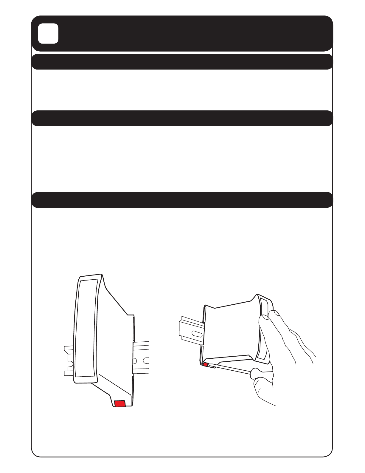
2.3 MOUNTING THE UNIT
1. The unit should be hooked over the top of the DIN rail and then pushed back into
location until the red tab at the bottom of the rear of the unit snaps behind the
lower edge of the DIN rail. (Fig.1)
2. The unit can be dismounted from the DIN rail by using a screwdriver to release the
red tab whilst lifting the unit upwards from the mounting rail. (Fig.2)
Fig.1 Fig.2
5 of 59
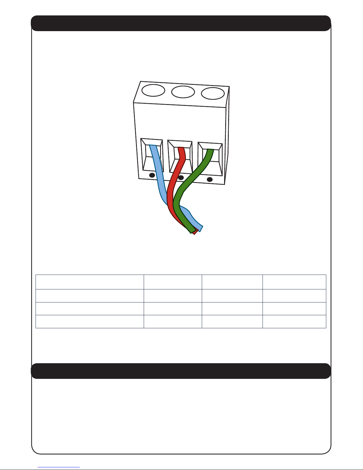
2.4 CONNECTING THE RS485 MODBUS INTERFACE
1. The RS485 Modbus cable should be connected to the terminal block on the lower
edge of the 3155 unit. Tighten the terminal block screws to grip the cable securely
ensuring that a sound electrical connection has been made.
The RS458 Modbus Interface wires are connected as follows:
2.5 CONNECTING THE NMEA2000® INTERFACE
1. The NMEA2000® interface cable on the unit should be connected to a nearby
NMEA2000® Tee connector (part number 3802).
2. The male end of the cable should be inserted into the female Tee connection
noting the position of the keyway in the plug and the socket.
3. The unit can be connected with power on or off without any damage.
4. Ensure that the locking ring is securely tightened so that
the connection remains sound.
Description EIA/TIA-485 Name Modbus Name
Transceiver Terminal 1, V1 Voltage B/B’ Data + D0
Transceiver Terminal 0, V0 Voltage A/A’ Data - D1
Signal Ground C/C’ Common Common
Fig.3 RS485 Connections
D0
D1
COM

3
CONFIGURATION
6 of 59
3.1 MODBUS COMMUNICATION PARAMETERS
The 3155 NMEA2000 to Modbus Gateway Modbus interface communications parameters are by
default set to 19,200 Baud, EVEN parity, 1 stop bit ex factory
The RS485 communications parameters can be changed at any time by setting the ADDR switch
to the following number and pressing the COM push button with power on according to the
following table:
Please note that if the chosen communications parameters are NOT set to the default then the
DefCm green led will NOT be illuminated.
The unit can be reset to the default values at any time by pressing the Set DefCom push button
when the unit has power on and the ADDR switch is set to “0”. When they are set to the default
value the DefCm green LED is illuminated.
ADDR switch position Communications Parameters
0
19,200 Baud, Even Parity, 1 stop bit (Default)
1 19,200 Baud, Odd Parity, 1 stop bit
2 19,200 Baud, No Parity, 2 stop bits
3 9,600 Baud, Even Parity, 1 stop bit
4 9,600 Baud, Odd Parity, 1 stop bit
5 9,600 Baud, No Parity, 2 stop bits
6 4,800 Baud, Even Parity, 1 stop bit
7
4,800 Baud, Odd Parity, 1 stop bit
8
4,800 Baud, No Parity, 2 stop bits

7 of 59
3.2 MODBUS SLAVE ADDRESS
• A single Modbus network may have a number of slave units attached and these
units MUST have each a unique slave address.
• The 3155 NMEA2000 to Modbus Gateway Slave Address can be set from 16 decimal
to 1 decimal by using the small rotary switch on the front panel labeled “Addr” as
per the following table:
3.3 MODBUS TERMINATION RESISTOR
Please note that this unit does NOT include any Modbus network termination resistor as the
master normally includes this. If this is not the case then a RS485 termination resistor MUST be
included in the Modbus Communication line
3.4 NMEA DEVICE INSTANCE
NMEA2000 requires a unique Device Instance for each 3155 NMEA2000 to Modbus Gateway on
a single network. This is settable from device instance 0 to Device Instance 15 using the lower
small rotary switch on the front panel labeled “Addr”. This can be set at any time regardless if
power is on or off. The switch counts from 0 – 9 then A – F being equivalent to Device Instance
0 – 15.
Please note that this switch also controls the Modbus Slave Address so a compromise address
that suits both interfaces should be chosen.
Switch Position Decimal Address Hex Address
0 16 0x10
1 17 0 x11
2 18 0x12
3 19 0x13
4 20 0x14
5 21
0x15
6 22
0x16
7 23
0x17
8 24
0x18
9 25
0x19
A 26
0x1A
B 27
0x1B
C 28
0x1C
D 29
0x1D
E 30
0x1E
F 31
0x1F
4
FRONT PANEL INDICATORS AND SWITCHES
8 of 59
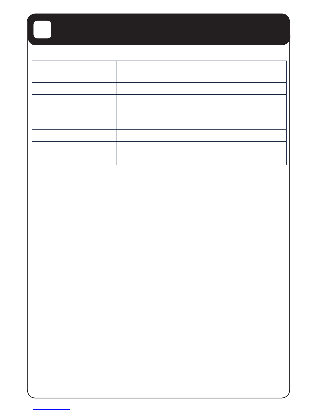
The front panel has the following LEDs:
The rotary switch is used to set the communications protocol, the Modbus Slave Device Address
and the NMEA2000 Instance. See 3.1 To 3.3 above
The pushbutton is used to capture the default communications protocol from the rotary switch.
LED Name Description
NMRx Receiving an NMEA2000® message
NMTx Transmitting an NMEA2000® message
MoRx Receiving a Modbus message
MoTx Transmitting a Modbus message
MoFlt Invalid Modbus message
CmFlt Communications error
PGN became Data Not Available
DefCm Default Communications Protocol in use

FAULT FINDING/TROUBLESHOOTING
5
9 of 59
The front panel indicators should be used to assist in fault nding as follows:
5.1 COMMUNICATIONS ERROR LEDs
If the CmFlt led is lit this means that the unit detected an error in the communications parameters being used on the Modbus interface. Please check that the transmission protocol EXACTLY
matches the Modbus Communications Parameters in section 3.1 above.
5.2 INVALID MODBUS MESSAGE ERROR LED
If the MoFlt led is lit this means that the unit received a Modbus message that it could not carry
out. This indicates that the communications protocol is probably correct but that the message
content was invalid. This could be either the wrong Modbus command or wrong data length
request.
5.3 UNMARKED LED – PGN BECAME DATA NOT AVAILABLE
This green led comes on if any PGN that has been received is not received for a period of great-
er than 10 seconds. This led will stay illuminated until the next power ff poer on cycle occurs.
This can indicate a failing or removed NMEA2000 device on the bus.

DATA NAMING CONVENTION
6
10 of 59
Because it is easy to misunderstand base numbering system it is being shown in this document
decimal / base 10 values are shown thus:10 = decimal value of ten
Hexadecimal / base 16 values are shown thus:0x10 = decimal value of sixteen.

MODBUS DATA REGISTERS
7
11 of 59
The unit can receive NMEA2000 information from
• 3 Engines
• 8 Fuel Tanks
• 8 Fresh Water Tanks
• 8 Grey Water Tanks
• 8 Black Water Tanks
• 8 Oil Tanks
• 3 Generators
• 3 AC Sources
• 8 Battery Banks
• 4 Battery Chargers
• 8 Banks each of up to 28 switches (224 switches)
The unit can also control the 8 banks of 28 switches individually or collectively
Read access to all registers can only be made using the Modbus Function Code 04 Read
Input Register command.
There is NO write access to any input registers except the Switch Bank Registers.
Note that if a NMEA2000 PGN is not available then the data elds will always read
0xFF which is the standard NMEA2000 value for “Data Not Available”
The information from the NMEA2000 connected devices is stored in 16 bit Input Registers
that can be accessed from the Modbus Interface according to the following tables:

12 of 59
7.1 Engine Instance 0 Registers
Engine Instance 0 – Single or PORT Engine
Hex
Addr
Dec
Addr
Data Field Data Type, Range and Resolution
0x0000 0000 Engine Oil Pressure Unsigned 16 bit integer
Range 0 – 6,553,200 Pa
Resolution 1x10E+2 Pa
0x0001 0001 Engine Oil Temp Unsigned 16 bit integer
Range 0 – 6,553.2 deg K
Resolution 1x10E-1 deg K
0x0002 0002 Engine Temp Unsigned 16 bit integer
Range 0 – 655.32 deg K
Resolution 1x10E-2 deg K
0x0003 0003 Alternator Voltage Signed 16 bit integer
Range ± 327.64 Volts
Resolution 1x10E-2 Volts
0x0004 0004 Fuel Rate Signed 16 bit integer
Range ± 3.2764 cu-m/hour
Resolution 1x10E-4 cu-m/hour
0x0005/
0x0006
0005/
0006
Total Engine Hours
Addr 0005 = MSW
Addr 0006 = LSW
Unsigned 32 bit integer
Range 0 – 4.295x10E+9 seconds
Resolution 1 second
0x0007 0007 Engine Coolant Pressure Unsigned 16 bit integer
Range 0 – 6,553,200 Pa
Resolution 1 x 10E+2 Pa
0x0008 0008 Fuel Pressure Unsigned 16 bit integer
Range 0 – 65,532,000 Pa
Resolution 1x10E+3 Pa
0x0009 0009 Engine Status 1
16 bit Status biteld
xxxx xxxx xxxx xxx1 = Check Engine
xxxx xxxx xxxx xx1x = Over Temperature
xxxx xxxx xxxx x1xx = Low Oil Pressure
xxxx xxxx xxxx 1xxx = Low Oil Level
xxxx xxxx xxx1 xxxx = Low Fuel Pressure
xxxx xxxx xx1x xxxx = Low System Voltage
xxxx xxxx x1xx xxxx = Low Coolant Level
xxxx xxxx 1xxx xxxx = Water Flow
xxxx xxx1 xxxx xxxx = Water in Fuel
xxxx xx1x xxxx xxxx = Charge Indicator
xxxx x1xx xxxx xxxx = Preheat Indicator
xxxx 1xxx xxxx xxxx = High Boost Pressure
xxx1 xxxx xxxx xxxx = Rev Limit Exceeded
xx1x xxxx xxxx xxxx = EGR System
x1xx xxxx xxxx xxxx = Throttle Position Sensor
1xxx xxxx xxxx xxxx = Emergency Stop
0x000A Engine Status 2 16 bit Status biteld
xxxx xxxx xxxx xxx1 = Warning Level 1

13 of 59
7.1 Engine Instance 0 Registers
xxxx xxxx xxxx xx1x = Warning Level 2
xxxx xxxx xxxx x1xx = Power Reduction
xxxx xxxx xxxx 1xxx = Maintenance Needed
xxxx xxxx xxx1 xxxx = Engine Comm Error
xxxx xxxx xx1x xxxx = Sub or Secondary Throttle
xxxx xxxx x1xx xxxx = Neutral Start Protect
xxxx xxxx 1xxx xxxx = Engine Shutting Down
xxxx xxx1 xxxx xxxx = Reserved
xxxx xx1x xxxx xxxx = Reserved
xxxx x1xx xxxx xxxx = Reserved
xxxx 1xxx xxxx xxxx = Reserved
xxx1 xxxx xxxx xxxx = Reserved
xx1x xxxx xxxx xxxx = Reserved
x1xx xxxx xxxx xxxx = Reserved
1xxx xxxx xxxx xxxx = Reserved
0x000B 0011 Percent Engine Load
Percent Engine Torque
2x Unsigned 8 bit integers
Range ± 124%, Resolution 1%
MSB = Load, LSB =Torque
0x000C 0012 Engine Speed Unsigned 16 bit integer
Range 0 – 16,383 RPM
Resolution ¼ RPM
0x000D 0013 Engine Boost Pressure Unsigned 16 bit integer
Range 0 – 6,553,200 Pa
Resolution 1x10E+2 Pa
0x000E 0 014 Engine Tilt/Trim Signed 8 bit integer (LSB)
Range ±124%
Resolution 1%
0x000F 0015 Transmission OiI Pressure
Unsigned 16 bit integer
Range 0– 6,553,200 Pa
Resolution 1x10E+2 Pa
0x0010 0016
Transmission Oil Temperature
Unsigned 16 bit integer
Range 0 – 6,553.2 deg K
Resolution 1x10E-1 deg K

14 of 59
7.2 Engine Instance 1 Registers
Engine Instance 1 – STARBOARD Engine
Hex
Addr
Dec
Addr
Data Field Data Type, Range and Resolution
0x 0011 0017 Engine Oil Pressure Unsigned 16 bit integer
Range 0 – 6,553,200 Pa
Resolution 1x10E+2 Pa
0x0012 0018 Engine Oil Temp Unsigned 16 bit integer
Range 0 – 6,553.2 deg K
Resolution 1x10E-1 deg K
0x0013 0 019 Engine Temp Unsigned 16 bit integer
Range 0 – 655.32 deg K
Resolution 1x10E-2 deg K
0x0 014 0020 Alternator Voltage Signed 16 bit integer
Range ± 327.64 Volts
Resolution 1x10E-2 Volts
0x0015 0021 Fuel Rate Signed 16 bit integer
Range ± 3.2764 cu-m/hour
Resolution 1x10E-4 cu-m/hour
0x 0 016/
0x0017
0022/
0023
Total Engine Hours
Addr 0020 = MSW
Addr 0021 = LSW
Unsigned 32 bit integer
Range 0 – 4.295x10E+9 seconds
Resolution 1 second
0x0 018 0024 Engine Coolant Pressure Unsigned 16 bit integer
Range 0 – 6,553,200 Pa
Resolution 1 x 10E+2 Pa
0x0019 0025 Fuel Pressure Unsigned 16 bit integer
Range 0 – 65,532,000 Pa
Resolution 1x10E+3 Pa
0x001A 0026 Engine Status 1
0x0 01B 0027 Engine Status 2
16 bit Status biteld
xxxx xxxx xxxx xxx1 = Check Engine
xxxx xxxx xxxx xx1x = Over Temperature
xxxx xxxx xxxx x1xx = Low Oil Pressure
xxxx xxxx xxxx 1xxx = Low Oil Level
xxxx xxxx xxx1 xxxx = Low Fuel Pressure
xxxx xxxx xx1x xxxx = Low System Voltage
xxxx xxxx x1xx xxxx = Low Coolant Level
xxxx xxxx 1xxx xxxx = Water Flow
xxxx xxx1 xxxx xxxx = Water in Fuel
xxxx xx1x xxxx xxxx = Charge Indicator
xxxx x1xx xxxx xxxx = Preheat Indicator
xxxx 1xxx xxxx xxxx = High Boost Pressure
xxx1 xxxx xxxx xxxx = Rev Limit Exceeded
xx1x xxxx xxxx xxxx = EGR System
x1xx xxxx xxxx xxxx = Throttle Position Sensor
1xxx xxxx xxxx xxxx = Emergency Stop

15 of 59
Engine Instance 1 – STARBOARD Engine
Hex
Addr
Dec
Addr
Data Field Data Type, Range and Resolution
0x 0011 0017 Engine Oil Pressure Unsigned 16 bit integer
Range 0 – 6,553,200 Pa
Resolution 1x10E+2 Pa
0x0012 0018 Engine Oil Temp Unsigned 16 bit integer
Range 0 – 6,553.2 deg K
Resolution 1x10E-1 deg K
0x0013 0019 Engine Temp Unsigned 16 bit integer
Range 0 – 655.32 deg K
Resolution 1x10E-2 deg K
0x0 014 0020 Alternator Voltage Signed 16 bit integer
Range ± 327.64 Volts
Resolution 1x10E-2 Volts
0x0015 0021 Fuel Rate Signed 16 bit integer
Range ± 3.2764 cu-m/hour
Resolution 1x10E-4 cu-m/hour
0x 0 016/
0x0017
0022/
0023
Total Engine Hours
Addr 0020 = MSW
Addr 0021 = LSW
Unsigned 32 bit integer
Range 0 – 4.295x10E+9 seconds
Resolution 1 second
0x0 018 0024 Engine Coolant Pressure Unsigned 16 bit integer
Range 0 – 6,553,200 Pa
Resolution 1 x 10E+2 Pa
0x0019 0025 Fuel Pressure Unsigned 16 bit integer
Range 0 – 65,532,000 Pa
Resolution 1x10E+3 Pa
0x001A 0026 Engine Status 1
16 bit Status biteld
xxxx xxxx xxxx xxx1 = Check Engine
xxxx xxxx xxxx xx1x = Over Temperature
xxxx xxxx xxxx x1xx = Low Oil Pressure
xxxx xxxx xxxx 1xxx = Low Oil Level
xxxx xxxx xxx1 xxxx = Low Fuel Pressure
xxxx xxxx xx1x xxxx = Low System Voltage
xxxx xxxx x1xx xxxx = Low Coolant Level
xxxx xxxx 1xxx xxxx = Water Flow
xxxx xxx1 xxxx xxxx = Water in Fuel
xxxx xx1x xxxx xxxx = Charge Indicator
xxxx x1xx xxxx xxxx = Preheat Indicator
xxxx 1xxx xxxx xxxx = High Boost Pressure
xxx1 xxxx xxxx xxxx = Rev Limit Exceeded
xx1x xxxx xxxx xxxx = EGR System
x1xx xxxx xxxx xxxx = Throttle Position Sensor
1xxx xxxx xxxx xxxx = Emergency Stop
0x0 01B 0027 Engine Status 2 16 bit Status biteld
xxxx xxxx xxxx xxx1 = Warning Level 1
xxxx xxxx xxxx xx1x = Warning Level 2

16 of 59
xxxx xxxx xxxx x1xx = Power Reduction
xxxx xxxx xxxx 1xxx = Maintenance Needed
xxxx xxxx xxx1 xxxx = Engine Comm Error
xxxx xxxx xx1x xxxx = Sub or Secondary Throttle
xxxx xxxx x1xx xxxx = Neutral Start Protect
xxxx xxxx 1xxx xxxx = Engine Shutting Down
xxxx xxx1 xxxx xxxx = Reserved
xxxx xx1x xxxx xxxx = Reserved
xxxx x1xx xxxx xxxx = Reserved
xxxx 1xxx xxxx xxxx = Reserved
xxx1 xxxx xxxx xxxx = Reserved
xx1x xxxx xxxx xxxx = Reserved
x1xx xxxx xxxx xxxx = Reserved
1xxx xxxx xxxx xxxx = Reserved
0x0 01C 0028 Percent Engine Load
Percent Engine Torque
2x Unsigned 8 bit integers
Range ± 124%, Resolution 1%
MSB = Load, LSB = Torque
0x0 01D 0029 Engine Speed Unsigned 16 bit integer
Range 0 – 16,383 RPM
Resolution ¼ RPM
0x0 01E 0030 Engine Boost Pressure Unsigned 16 bit integer
Range 0 – 6,553,200 Pa
Resolution 1x10E+2 Pa
0x0 01F 0031 Engine Tilt/Trim Signed 8 bit integer (LSB)
Range ±124%
Resolution 1%
0x0020 0032 Transmission OiI Pressure Unsigned 16 bit integer
Range 0– 6,553,200 Pa
Resolution 1x10E+2 Pa
0x0021 0033 Transmission Oil Tempera-
ture
Unsigned 16 bit integer
Range 0 – 6,553.2 deg K
Resolution 1x10E-1 deg K

17 of 59
7.3 Engine Instance 2 Registers
Engine Instance 2 – THIRD Engine
Hex
Addr
Dec
Addr
Data Field Data Type, Range and Resolution
0x0022 0034 Engine Oil Pressure Unsigned 16 bit integer
Range 0 – 6,553,200 Pa
Resolution 1x10E+2 Pa
0x0023 0035 Engine Oil Temp Unsigned 16 bit integer
Range 0 – 6,553.2 deg K
Resolution 1x10E-1 deg K
0x0024 0036 Engine Temp Unsigned 16 bit integer
Range 0 – 655.32 deg K
Resolution 1x10E-2 deg K
0x0025 0037 Alternator Voltage Signed 16 bit integer
Range ± 327.64 Volts
Resolution 1x10E-2 Volts
0x0026 0038 Fuel Rate Signed 16 bit integer
Range ± 3.2764 cu-m/hour
Resolution 1x10E-4 cu-m/hour
0 x 0 0 27/
0x0028
0039/
0040
Total Engine Hours
Addr 0035 = MSW
Addr 0036 = LSW
Unsigned 32 bit integer
Range 0 – 4.295x10E+9 seconds
Resolution 1 second
0x0029 0041 Engine Coolant Pressure Unsigned 16 bit integer
Range 0 – 6,553,200 Pa
Resolution 1 x 10E+2 Pa
0x002A 0042 Fuel Pressure Unsigned 16 bit integer
Range 0 – 65,532,000 Pa
Resolution 1x10E+3 Pa
0x002B 0043 Engine Status 1 16 bit Status biteld
xxxx xxxx xxxx xxx1 = Check Engine
xxxx xxxx xxxx xx1x = Over Temperature
xxxx xxxx xxxx x1xx = Low Oil Pressure
xxxx xxxx xxxx 1xxx = Low Oil Level
xxxx xxxx xxx1 xxxx = Low Fuel Pressure
xxxx xxxx xx1x xxxx = Low System Voltage
xxxx xxxx x1xx xxxx = Low Coolant Level
xxxx xxxx 1xxx xxxx = Water Flow
xxxx xxx1 xxxx xxxx = Water in Fuel
xxxx xx1x xxxx xxxx = Charge Indicator
xxxx x1xx xxxx xxxx = Preheat Indicator
xxxx 1xxx xxxx xxxx = High Boost Pressure
xxx1 xxxx xxxx xxxx = Rev Limit Exceeded
xx1x xxxx xxxx xxxx = EGR System
x1xx xxxx xxxx xxxx = Throttle Position Sensor
1xxx xxxx xxxx xxxx = Emergency Stop
 Loading...