

Page 1

PRODUCT IMAGE
Oceanic Ltd, Pountney Street, Wolverhampton, WV2 4HX
Phone: 01902 450 550 [email protected] www.oceanic-saunas.co.uk
Sauna & Steam
SAUNA HEATER
with OCSB/LB CONTROLLER
Assembly and operating manual
31.06.16
Page 2

Sauna & Steam
Oceanic Saunas 01902 450 550 sales@oceanic-saunas.co.uk www.oceanic-saunas.co.uk
2
Sauna Heater Manual
Table of contents
1. Introduction . . . . . . . . . . . . . . . . . . . . . . . . . . . . . . . . . . . . . . . . . . . . .3
2. Important Notes . . . . . . . . . . . . . . . . . . . . . . . . . . . . . . . . . . . . . . . . . . . 3
3. Safety Precautions . . . . . . . . . . . . . . . . . . . . . . . . . . . . . . . . . . . . . . . . .3
4. Electrical connection . . . . . . . . . . . . . . . . . . . . . . . . . . . . . . . . . . . . . . . . 3
4.1. Installation overview . . . . . . . . . . . . . . . . . . . . . . . . . . . . . . . . . . . . . . 4
4.2. Circuit Diagram . . . . . . . . . . . . . . . . . . . . . . . . . . . . . . . . . . . . . . . . . . 4
5. Sauna Heater Parameters . . . . . . . . . . . . . . . . . . . . . . . . . . . . . . . . . . . . . 5
5.1. Sauna Heater Parts Description . . . . . . . . . . . . . . . . . . . . . . . . . . . . . . . . 5
5.2. Controller parameters . . . . . . . . . . . . . . . . . . . . . . . . . . . . . . . . . . . . . . 5
5.3. Control Box Circuit Diagram . . . . . . . . . . . . . . . . . . . . . . . . . . . . . . . . . . 6
5.4. Single Phase connection upto 9kw . . . . . . . . . . . . . . . . . . . . . . . . . . . . . 7
5.5. Controller Parts Description . . . . . . . . . . . . . . . . . . . . . . . . . . . . . . . . . . 8
5.6. Control Box Frame and Parts . . . . . . . . . . . . . . . . . . . . . . . . . . . . . . . . . 9
6. Temperature Sensor . . . . . . . . . . . . . . . . . . . . . . . . . . . . . . . . . . . . . . . 10
6.1. Parts Description . . . . . . . . . . . . . . . . . . . . . . . . . . . . . . . . . . . . . . . . 10
6.2. Temperature Sensor Parameters . . . . . . . . . . . . . . . . . . . . . . . . . . . . . . 10
7. Installation . . . . . . . . . . . . . . . . . . . . . . . . . . . . . . . . . . . . . . . . . . . . . 11
7.1. Minimum Clearances . . . . . . . . . . . . . . . . . . . . . . . . . . . . . . . . . . . . . 12
7.2. Installation for sauna heater . . . . . . . . . . . . . . . . . . . . . . . . . . . . . . . . . 13
7.3. Installation for controller . . . . . . . . . . . . . . . . . . . . . . . . . . . . . . . . . . 13
7.4. Installing the temperature sensor . . . . . . . . . . . . . . . . . . . . . . . . . . . . . 14
8. Sauna heater, controller and temperature sensor connection drawing . . . . . . . 14
9. Testing and Operation . . . . . . . . . . . . . . . . . . . . . . . . . . . . . . . . . . . . . . 15
9.1. Testing . . . . . . . . . . . . . . . . . . . . . . . . . . . . . . . . . . . . . . . . . . . . . . 15
9.2. Setting time and temperature: . . . . . . . . . . . . . . . . . . . . . . . . . . . . . . . 16
9.3. Door Interlock . . . . . . . . . . . . . . . . . . . . . . . . . . . . . . . . . . . . . . . . . 16
10. Trouble shooting Guide . . . . . . . . . . . . . . . . . . . . . . . . . . . . . . . . . . . . . 17
11. Maintenance . . . . . . . . . . . . . . . . . . . . . . . . . . . . . . . . . . . . . . . . . . . . 18
11.1. Sauna Heaters & Sauna Cabins Maintenance . . . . . . . . . . . . . . . . . . . . . . 18
11.2. Sauna Maintenance . . . . . . . . . . . . . . . . . . . . . . . . . . . . . . . . . . . . . . 18
11.3. Maintenance Checks . . . . . . . . . . . . . . . . . . . . . . . . . . . . . . . . . . . . . 18
11.4. Sauna Heater: . . . . . . . . . . . . . . . . . . . . . . . . . . . . . . . . . . . . . . . . . . 18
11.5. Sauna Cabin . . . . . . . . . . . . . . . . . . . . . . . . . . . . . . . . . . . . . . . . . . . 19
12. Warranty & After Sales . . . . . . . . . . . . . . . . . . . . . . . . . . . . . . . . . . . . . . 19
Page 3

Sauna & Steam
Oceanic Saunas 01902 450 550 sales@oceanic-saunas.co.uk www.oceanic-saunas.co.uk
3
Sauna Heater Manual
1. Introduction
Thank you for choosing to buy our Oceanic sauna heater, please take the time to read these
instructions before you begin as they contain important information about the installation and
maintenance requirements.
Depending upon the size of cabin heaters from 3kW to 9kW can be used in single or three phase.
2. Important Notes
• Read the manual before installation and operation.
• This equipment is intended for indoor use only
• This equipment is not intended for marine use
• This Equipment must be installed by competent person.
• This equipment must be connected to an RCD protected all pole isolator.
• Disconnect the power supply before exposing electrical connections.
• The sauna heater should not be used for any other purpose
• Do not cover the sauna heater or allow contact with ammable materials such as toweling –
Risk of re.
• Do not operate sauna heater without sauna stone
• Do not touch the heater when operational as it is very hot
3. Safety Precautions
• Elderly persons, pregnant women, or these suering heart disease, high blood pressure,
diabetes or not in good health are advised to seek medical opinion before using a sauna room;
• Do not smoke in the sauna room;
• Avoid using the sauna room immediately after strenuous exercise;
• Do not use the sauna room when under the inuence of alcohol;
• Leave the sauna room at once if you feel sleepy, sick or uncomfortable;
• Ensure there is good ventilation for the sauna room
• We do not recommend this product is used by children under 16 years old unless they are
supervised by an adult
• This appliance is not intended for use by persons including children with reduced physical,
sensory or mental capabilities or lack of experience unless they have been given supervision
or instruction concerning the use by a person responsible for their safety
• Commercial operators should post a notice of these precautions in a prominent position
4. Electrical connection
A qualied electrician will have no problem installing this system with the provided wiring
schematic and with the help of the circuit diagram mounted inside the respective control unit.
According to the valid regulations, the electrical connection of the sauna and the control box has
to be carried out by an authorised electrician. In case of a warranty claim, you are kindly requested
to present a copy of the invoice from the electrician.
Page 4
Sauna & Steam
Oceanic Saunas 01902 450 550 sales@oceanic-saunas.co.uk www.oceanic-saunas.co.uk
4
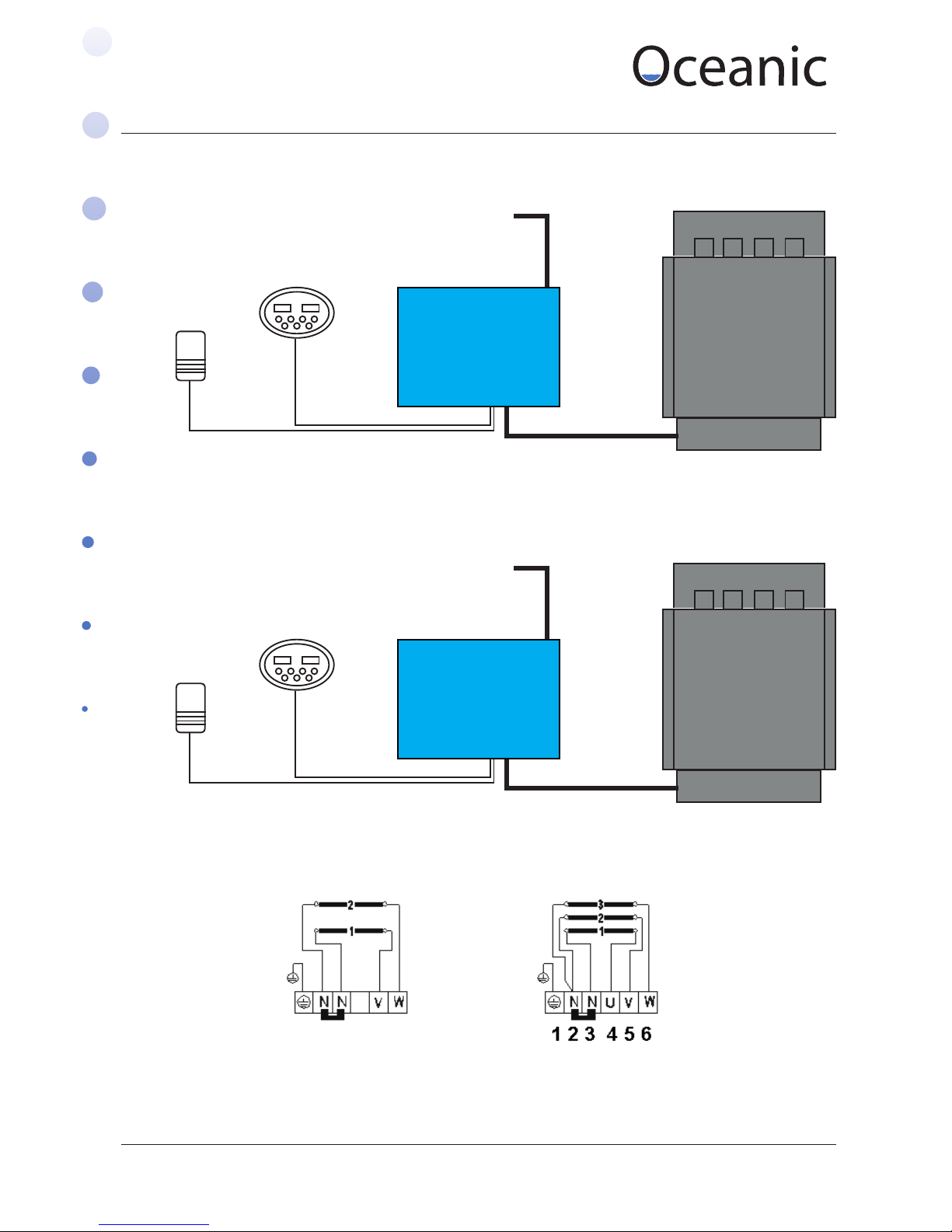
OCSB Keypad
5V DC
OCSB Keypad
5V DC
Temperature
Sensor
Temperature
Sensor
OC Wall Hung
Heater 3 - 4kW
OC Wall Hung
Heater 6 - 9kW
Mains Power
240 1N~
Mains Power
240 1N~ / 400V 3N~
OCSB/LB Contol Box
OCSB/LB Contol Box
4 core heat proof silicon cable
5 core heat proof silicon cable
Sauna Heater Manual
OCS60B~OCS90B Circuit diagram
4.1. Installation overview
4.2. Circuit Diagram
OC30~OC40 Circuit diagram
Use 4 core cable Use 5 core cable
1 2 3 4 5 6
Page 5
Sauna & Steam
Oceanic Saunas 01902 450 550 sales@oceanic-saunas.co.uk www.oceanic-saunas.co.uk
5
Sauna Heater Manual
5. Sauna Heater Parameters
OSC Series Sauna Heater Parameter
Model Power
(KW)
Voltage
(V)
Phase
(N~)
Current
(A)
Heater
Elements
Sauna
Stone (kg)
Dimensinos
LxWxH (mm)
OCS30 3 230 1 13 2 12-14
410 x 280 x 570
OCS40 4 230/400 1/3 17 2 13-15
OCS45 4.5 230/400 1/3 19/6.5 3 14-16
OCS60 6 230/400 1/3 26.4/8.7 3 16-18
OCS80 8 230/400 1/3 34.8/13 3 18-20
OCS90 9 230/400 1/3 39/14 3 18-20
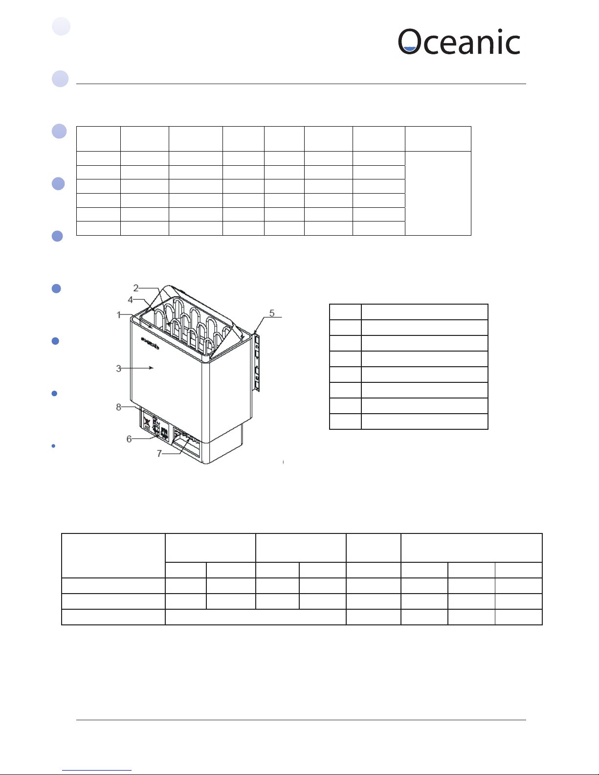
5.1. Sauna Heater Parts Description
No. Parts
1 Inner shell
2 Stone bracket
3 Shell
4 Heat element
5 Fix bracket
6 Cover Panel
7 Terminal
5.2. Controller parameters
Model Input Output Load
power
Size (mm)
1N~ 3N~ 1N~ 3N~ (Kw) L W H
OCSB Control box 230V 400v 230V 400v 2.5~8kw 310 260 70
OCSB Control box 400v 400v 9kw 310 260 70
OCSB Keypad Voltage:DC5V 2.5~20kw 150 92 22
Page 6
Sauna & Steam
Oceanic Saunas 01902 450 550 sales@oceanic-saunas.co.uk www.oceanic-saunas.co.uk
6
Sauna Heater Manual
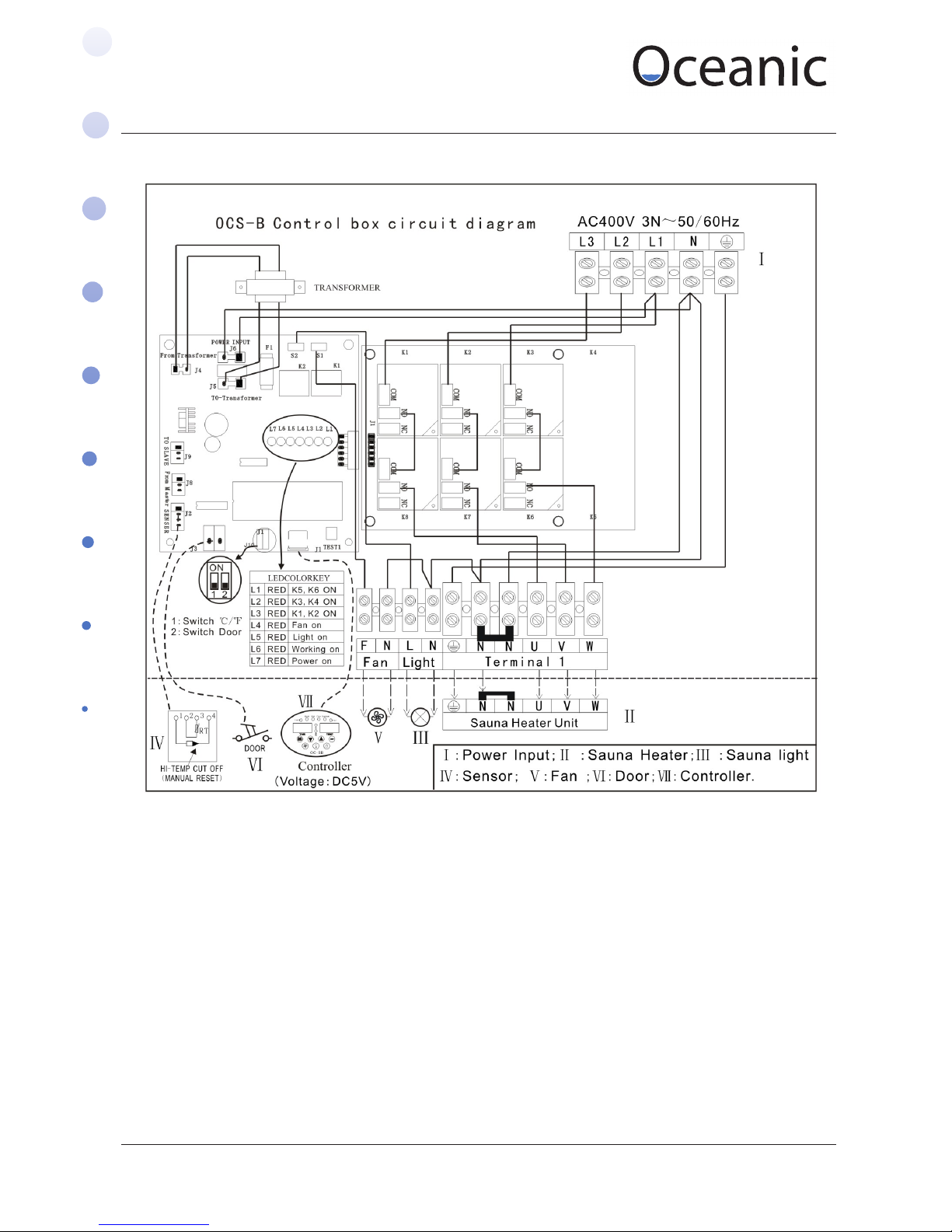
5.3. Control Box Circuit Diagram using three phase connection
Page 7
Sauna & Steam
Oceanic Saunas 01902 450 550 sales@oceanic-saunas.co.uk www.oceanic-saunas.co.uk
7
Sauna Heater Manual
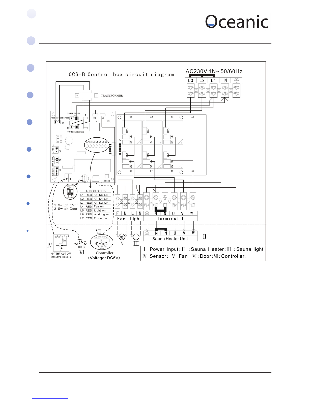
5.4. Control Box Circuit Diagram using single connection
Page 8
Sauna & Steam
Oceanic Saunas 01902 450 550 sales@oceanic-saunas.co.uk www.oceanic-saunas.co.uk
8
Sauna Heater Manual
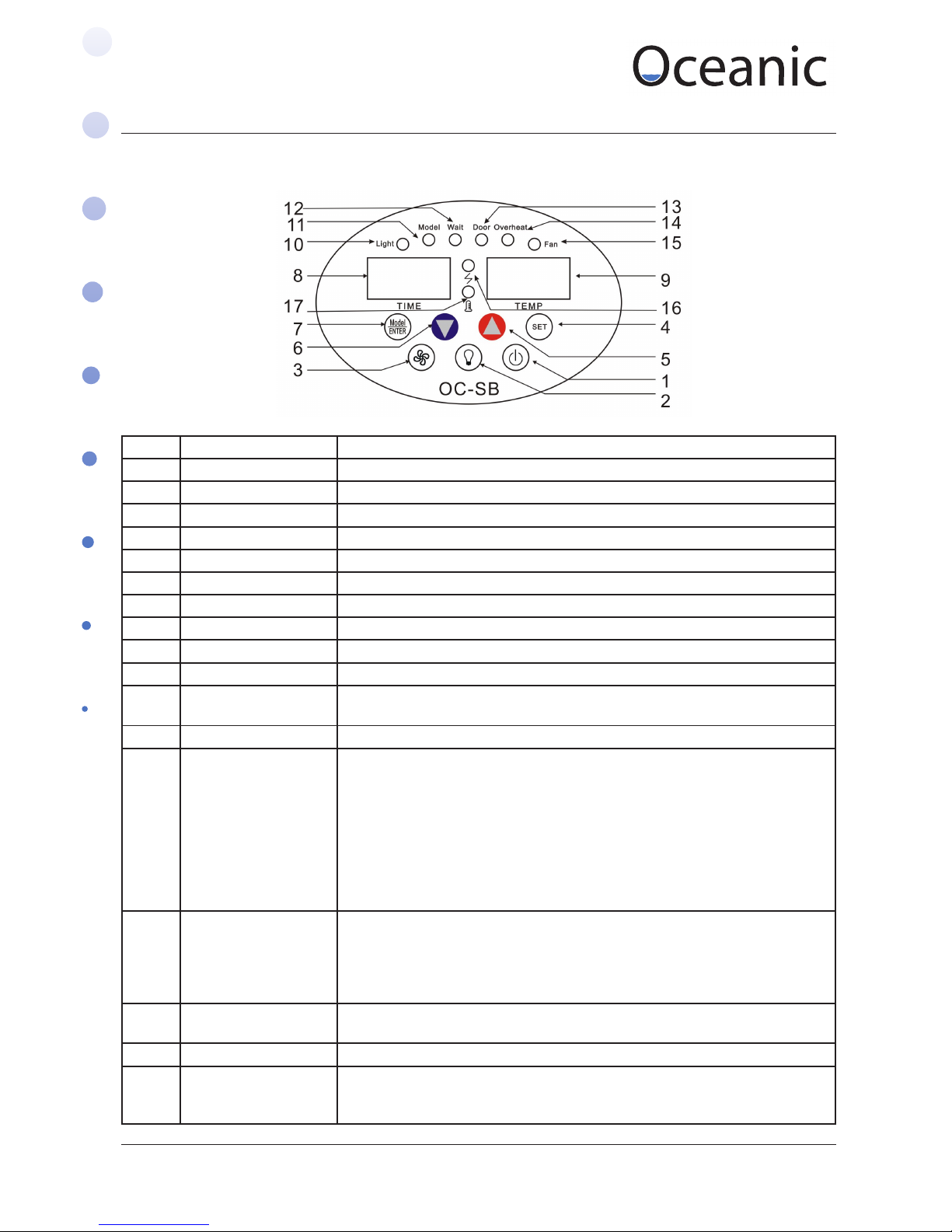
5.5. Controller Parts Description
No. Description Function instruction
1 On/o button Push to operate
2 Light button Push to operate for sauna room light
3 Fan button Push to operate for control box fan
4 Setting button Preset time and temperature and the setting conrmation
5 Increase button Press to increase
6 Increase button Press to decrease
7 Mode button Change working mode
8 Time display Display working time or waiting time to work
9 Temp. display Display temperature
10 Light LED Indictor Led for sauna room lamp
11 Model LED Indictor LED for working mode, on mean under A model ,sauna heater is
working
12 Wait LED Indicator LE D for working mode, on mean under B waiting to work
13 Sauna room
Door(interlock)
indicator LED
indicator LED is on: the sauna heater stop working ,there is control signal
to control box main circuit board when the door is open , the default is the
connection switch is downward (opposite side of ON), when the door is open ,
there is on signal to circuit board , the LED is on and sauna heater stop work.
Such as on sauna room door install a switch connect to circuit board , the switch
‘s on or o signal can control sauna heater work or stop. when you need the
switch send o signal to working , the default is ok, when you need the sauna
heater under the on signal to work , just push the switch circuit board to “on”
side”
14 High temperature LED indicator LED is on , sauna heater stop work . the sauna room temperature
higher then 120 centigrade . high temperature cut o switch works, when the
temperature in sauna room down to 100 centigrade , and nd out the high
temperature problem then preset the switch by hand
15 Fan LED Fan is on - not used in any Oceanic Saunas
16 Heating LED On means the heat element is working
17 Stop working LED indicator LED for stop working , the sauna room temperature exceed the preset
temperature , the heat element pause(when temperature 2 centigrade lower
than preset temperature ,sauna heater will work again,
Keypad Buttons and LEDS
Page 9
Sauna & Steam
Oceanic Saunas 01902 450 550 sales@oceanic-saunas.co.uk www.oceanic-saunas.co.uk
9
Sauna Heater Manual
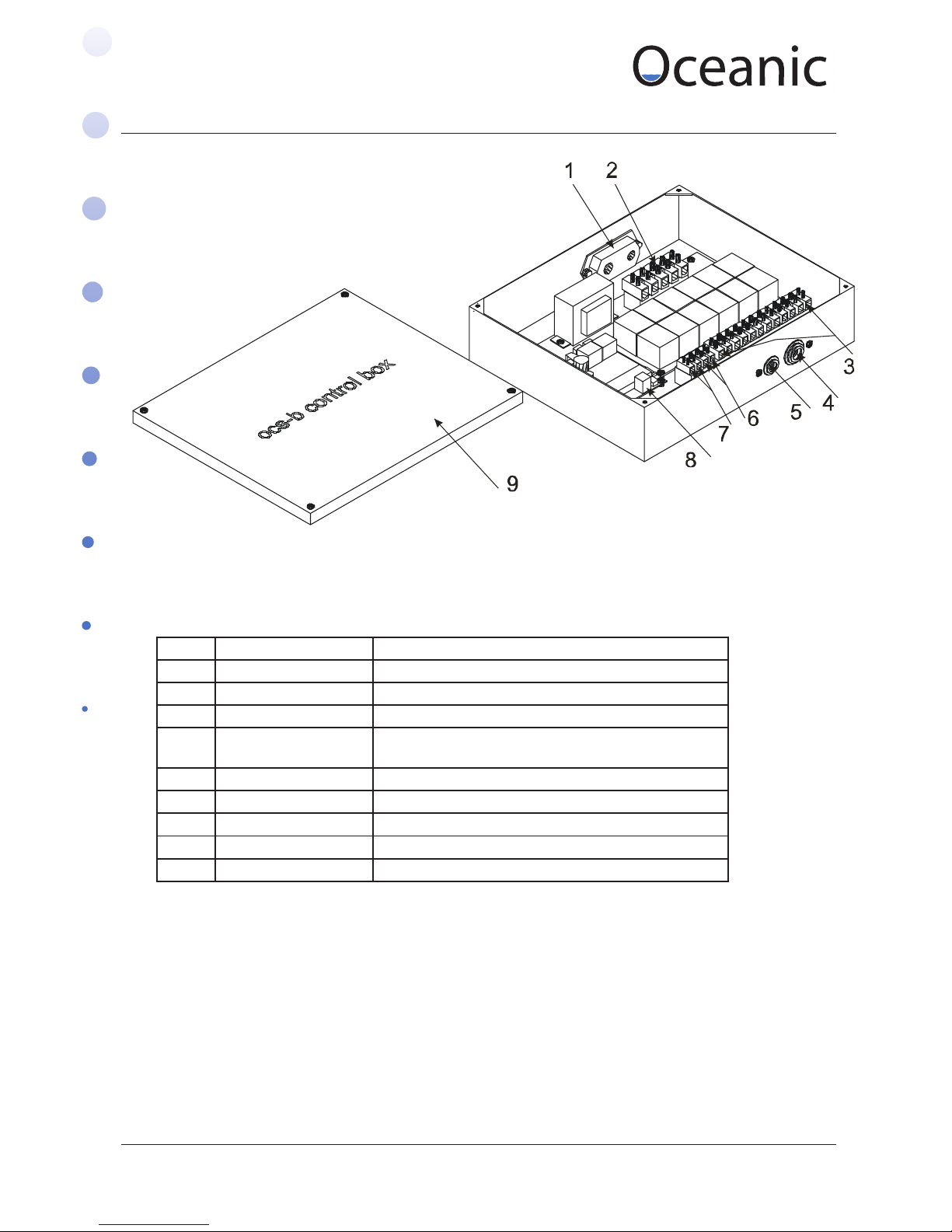
5.6. Control Box Frame and Parts
Control box instruction
No. Description Function instruction
1 Wire anchorage Route of wire entry and fasten wires
2 terminal Connect to the power supply
3 Terminal Connect to heater
4 Heater ,light and fan
output
Outlet of wires to heater ,light and fan and fasten wires
5 Control cable entry The entry of control cable
6 Light terminal Connect to light wire
7 Fan terminal Connect to fan wire
8 Control panel terminal Connect to control cable
9 Cover cover
Page 10
Sauna & Steam
Oceanic Saunas 01902 450 550 sales@oceanic-saunas.co.uk www.oceanic-saunas.co.uk
10
Sauna Heater Manual
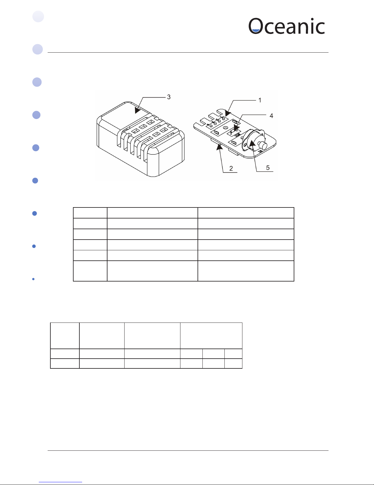
6. Temperature Sensor
6.1. Parts Description
Model Detected
scope
Cut o on high
temperature
Size
oC oC L W H
OC-S 0~110 120 76 42 27
6.2. Temperature Sensor Parameters
No. Parts Description
1 Circuit board Circuit board
2 Bracket Bracket
3 Cover Protects the electronics
4 Heat resistance Detects temperature
5 High Temp cut of switch When temperature in
sauna room exceed 120 oC
Page 11

Sauna & Steam
Oceanic Saunas 01902 450 550 sales@oceanic-saunas.co.uk www.oceanic-saunas.co.uk
11
Sauna Heater Manual
7. Installation
Conrm the model you have selected is suitable for your sauna room, please refer to the table
below.
i. Ensure the power supply is suitable for the sauna heater
ii. Isolate the power supply before installation. The sauna heater will be controlled via the
iii. The installation position must comply with the minimum distance in the table below and in
the diagrams on the following page
iv. The minimum height of your sauna room must be 1900mm, please refer diagrams on
following page
v. Do not install the sauna heater on the oor or in a cabinet
vi. Do not cover the sauna heater back with asbestos cement or similar material
vii. The wire which enters the sauna room must be type 60245 IEC 66 HO7RN-F (BSEN 6141) please
refer to table below
viii. Do not install two or more sauna heaters in one sauna room.
ix. The sauna heater becomes very hot when operating and must be guarded to protect incase of
accidental contact, please see the sizes in g D and also refer to charts below and on following
page
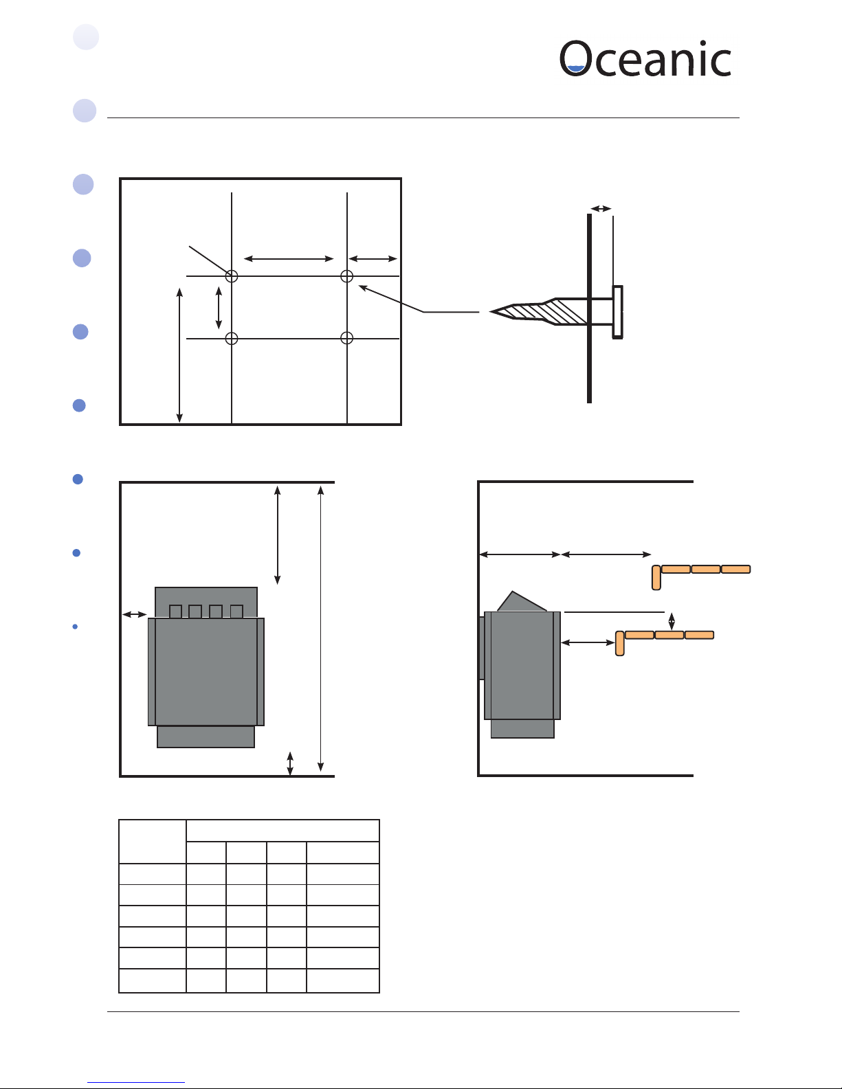
x. The upper supporting screws must be xed tightly, there is a 3mm gap between the screw
head and wall (refer g A, g B), additional retaining screws should be inserted into the round
holes to prevent the heater being lifted.
xi. The stauna controller can be mounted inside or outside of the cabin using the wiring panel
provided.
xii. The controller should be kept at a height of between 1200MM-1500MM so that it is easily
controlled and operated
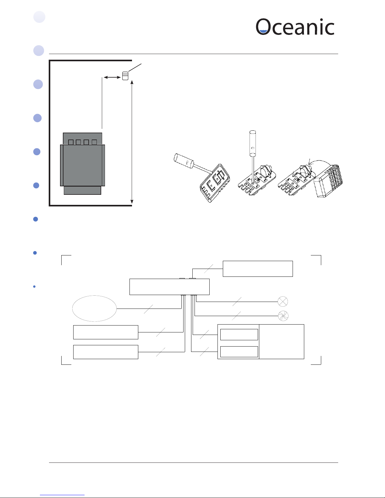
xiii. Temperature sensors should be installed in sauna room but not directly above sauna heater,
the height should be 1500-1800mm from oor. The horizontal distance to sauna heater should
exceed 500mm
Model Sauna Room Min Distance from Sauna
(mm)
Current (A) Fuse (A)
Volume (m3) Min
height
Distance to shelf
over 500mm
above the oor
Ceiling Floor 230V
1N~
400V
3N~
230v
1N~
400V
3N~
Min Max
0CS30 2 4 1900 50 1100 180 16 / 20 /
0CS40 3 5 1900 50 1100 180 20 10 25 /
OCS45 4 6 1900 80 1100 180 20 10 25 10
OCS60 5 8 1900 150 1100 180 32 16 40 16
OCS80 7 11 1900 200 1100 180 45 16 60 20
OCS90 8 12 1900 200 1100 180 45 20 60 20
Page 12
Sauna & Steam
Oceanic Saunas 01902 450 550 sales@oceanic-saunas.co.uk www.oceanic-saunas.co.uk
12
Sauna Heater Manual
370
B
Min 1900
C D
50
20
Min 180
Min 1100
A
3mm gap between
screw head and wall
All sizes in mm
Supporting Screw
6mm x 40mm
(4pcs)
3.5
150
600
7.1. Minimum Clearances
Fig. A Fig. B
Fig. C Fig. D
Model
Minimum Distance (mm)
A B C D
OCS30 50 70 280 100
OCS40 50 70 280 100
OCS45 80 100 280 100
OCS60 100 120 280 150
OCS80 130 150 280 200
OCS90 130 150 280 200
Page 13
Sauna & Steam
Oceanic Saunas 01902 450 550 sales@oceanic-saunas.co.uk www.oceanic-saunas.co.uk
13
Sauna Heater Manual
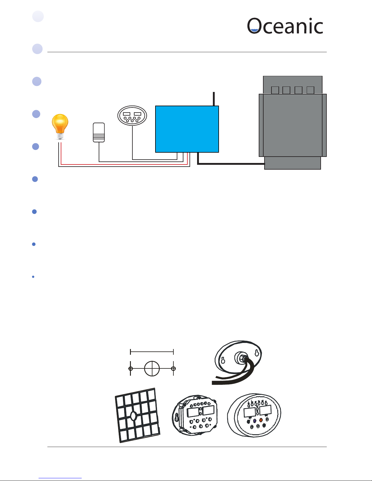
7.2. Installation for sauna heater
i. Refer the installation drawings on the previous page, Fix screws and hang sauna heater on
wall
ii. Remove the cover panel & connect power supply wire & control cable through the knock-
out holes to the Terminal as in the diagram above and replace the cover panel.
7.3. Installation for controller
Ideally the control box should be installed at a height of approximately 1200mm for ease of use.
Installation method:
• Drill a 40mm diameter hole through the wall.
• Pull the front o the keypad, you may nd it easier with a small at electrical screw driver.
• Pin the control cable (6 cores) to the relevant ports.
• Install the control so it sits at on the wall. Fix using the screw holes 118mm apart.
• Put the keypad cover back on, check the cover is completely on so that all the buttons click
when pushed.
OCSB Controller
5V DC
Temperature
Sensor
Lighting
OC Wall Hung
Heater
OCSB/LB Contol Box
Mains Power in
If using single phase link
across L1, L2, L3 with copper
bridges or pieces of cut wire
5 core (or 4 core for 3kw and 4kw units) heat proof
silicon cable must be used between the controller and
heater unit. This is because the controller heats three
elements individually when the temperature in the
room is reached two will turn o.
240 V AC mains power
supply for the lights
LN
118mm
Page 14
Sauna & Steam
Oceanic Saunas 01902 450 550 sales@oceanic-saunas.co.uk www.oceanic-saunas.co.uk
14
Sauna Heater Manual
8. Sauna heater, controller and temperature sensor connection drawing
1800
Temperature Sensor
500
7.4. Installing the temperature sensor
i. Install the temperature sensor as in the
diagram opposite
ii. Open the cover with a screwdriver
iii. Fix the bottom of the temperature
sensor on to wall with screw
iv. Replace the cover.
OC-SB
Controller
6
2
5
Terminal 1
Sauna heater
2
Fan
Door InterLock Switch
INPUT POWER
400V 3N~ 50/ 60Hz
OCS-B Control BOX
Temperature Sensor
lamp
Terminal 2
5
2
4
5
INPUT POWER
400V 3N~ / 230V 1N~
OCSB/LB Control Box
Page 15
Sauna & Steam
Oceanic Saunas 01902 450 550 sales@oceanic-saunas.co.uk www.oceanic-saunas.co.uk
15
Sauna Heater Manual
9. Testing and Operation
9.1. Testing
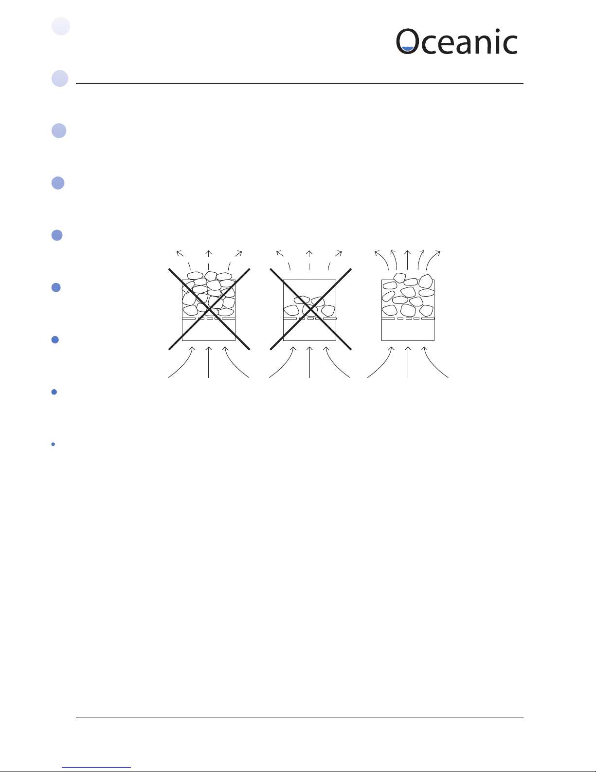
i. After checking that the sauna heater installation is correct, put the sauna stone in place (note
we recommend washing the stones thoroughly in water to remove any dust before the rst
use). Put the larger stones at the bottom and smaller stones on top. Take care not to pack the
stones too tightly other wise the air will not be able to circulate around the elements which can
cause premature failure, but do make sure to cover the elements completely. Note that it will
be necessary to change the stones from time to time as they will gradually crumble with use.
For commercial users this is probably every year, for domestic users once every several years,
depending upon use.
ii. Before connecting to the power supply check the sauna heater and make sure there are
no ammable items on or around the heater, please note that on the rst use the elements
and stones may smoke slightly and give o a smell – please ensure the sauna cabin is well
ventilated.
iii. Connect to power supply, press “ON/OFF “, temp and time windows will display data, LED
shows the sauna’s heating status when the light is on, the temperature of sauna room will rise
and will achieve the preset temperature (the default settings are 75 oC/187oF, work time is 2
hours) see chart on the following page.
iv. When the time has nished counting down and the time window displays “0”, the controller
and heater will shut down automatically.
v. The sauna heater has a sequential heating function so that the heater can work economically.
When the heater is rst turned on all the elements will work together to reach the target
temperature, when the target is reached one element will be left working to keep the
target temperature constant (for OCS30, OCS40 ,one bank will stop ). When sauna room
temperature goes 2oC/ 4 oF above the target temperature all heat elements will stop. When
the temperature of the sauna goes below the target temperature, one bank heat element
will work again, when the temperature goes 2oC/ 4 oF below the target temperature, all heat
elements will work again.
vi. Light button: Turns sauna light on/o
vii. Use temperature switch button to change the temperature display between centigrade and
Fahrenheit
viii. The Controller has a timing device so you can set a time when you want the heater to power
up, this can be set from 0~12 hours as shown in the chart below. When the controller is in
B Mode (Timer mode) the heater can’t operate, but when B Mode reaches “0” or the “Mode
Button” is pressed the heating function will start (A Mode).
Page 16
Sauna & Steam
Oceanic Saunas 01902 450 550 sales@oceanic-saunas.co.uk www.oceanic-saunas.co.uk
16
Sauna Heater Manual
9.2. Setting time and temperature:
The default settings for temperature are: 75oC/187oF. For preset operation time: 2 hours. These can
be adjusted easily, if the electricity supply is lost the controller will return to default settings.
• When the sauna is turned on the time settings will work under A mode (A mode LED is on),
the time window will display the last time that was set. Press” SET” key the time display window
will ash. press “p ” or “q ” to adjust the time, every press the time will increase or reduce 10
minutes. once the desired setting is reached press “ MENU/ENTER” the window will stop ashing.
You can adjust from the time from 10 minutes to 8 hours. Note the controller has a memory
function, if the power supply is not cut o the next time you turn on steam generator the time you
selected will be the default time.
• To set your heater to come on at a certain time (for example: if you plan to watch a lm and
want the sauna to start heating up half way through so its ready at the end of the lm) you can
use the B mode setting which can be set if you press the “MENU/ENTER”” and the time window
will display 4:00, now Press” SET” key the time display window will ash. press “p ” or “q ” to
adjust the time, every press the time will increase or reduce 10 minutes. once the desired setting is
reached press “MENU/ENTER ” the window will stop ashing., when it reaches “0” it will switch over
to A Mode and the heater will turn on. (Remember to set the time you want the heater on for on A
Mode before setting B Mode)
• For quick time adjustment: hold the “p ” or “q ” and it will count continuously up or
down, when it reaches the time you want release and it will stop.
• Temperature: switch button you can switch between centigrade and Fahrenheit.
• To adjust temperature: Press “SET ” once after you nish setting the time or otherwise
twice the temperature window will ash, enter the required temperature by pressing “p ” or “q
” to adjust - every press will increase or reduce 1OCor 2OF.you can adjust from 50oC-110oC 122oF230oF once the required temperature has been set press “ MENU/ENTER” key the window will stop
ashing.
9.3. Door Interlock
When used in commercial situations such as public buildings where the countdown timer is set to come on
in advance a door interlock switch must be connected as described in the circuit diagram on page 6 7 and
14. Before B mode can be activated the sauna room must be checked by the responsible person to ensure
there is no hazard such as combustible material left over the sauna stove etc – then the sauna cabin door
must be closed before the setting can be made. Once the advance timer begins the countdown sequence
the timing will stop if the door is opened and will not restart again until it is reset.
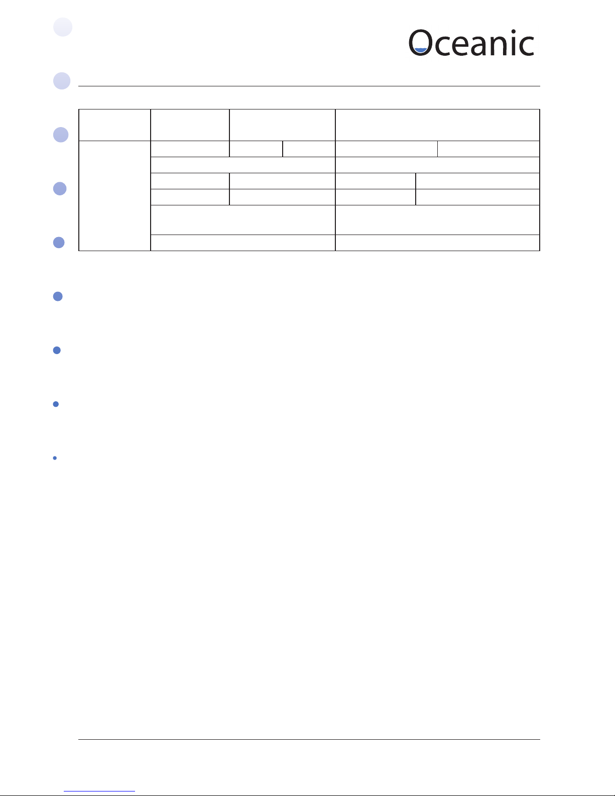
Default Controller Settings
Model Default Mode Default Temp oC/oF Temperature adjust scope oC
OCSB/LB
A 75 oC 187 oF 50-110 oC 122-230 oF
Default Time Time adjust scope
Working time Waiting Work time Wait time
2hrs 4hrs 10mins - 8hrs 0-12 hrs
Time adjustment per button press Temperature adjustment per button
press
10 mins 1oC /2 oF
Page 17

Sauna & Steam
Oceanic Saunas 01902 450 550 sales@oceanic-saunas.co.uk www.oceanic-saunas.co.uk
17
Sauna Heater Manual
10. Trouble shooting Guide
Please Note that we recommend a suitably qualied person carries out all repairs.
Trouble description Cause Solutions
There is no display on the
control panel when the on/o
switch is pressed
There is a problem with;
1.Power supply or
2. Circuit board transformer or
3. Fuse
1. Chck the power supply. If
the power supply indicator
LED L1 (red) is on check the
wire.
2. Change the controller
The controller is on but the
sauna heater doesn’t work
1 .The sauna heater hasn’t
been connected
2. There is a problem with the
controller
1. Check the connection, refer
to page 6 and 12.
2. Change the controller
OverHeat LED is on 1. The temperature sensor
hasn’t been connected
correctly
2. The high tempeature cut o
switch is turned o
1. Check the connection to the
temperature sensor.
2. Check if the high
temperature cut o switch is
turned o, i yes, reset by hand
Door LED is on During the advance timer
countdown sequence ,the
sauna room door has been
opened , the timing stoped
and will not restart again until
it is reset.
Reset counter down timer
Wait LED is on red Sauna heater is under B mode Press the Mode button to
change to A mode (heating
Mode)
Temperature windows display
- - Lo or - -H
o
1. Thermometer isn’t
connected or cable is broken
2. The temperature is lower
than 0oC .
3. The temperature is higher
than 115oC
1. -- LoC means temperature
sensor hasn’t connected or the
temperature is lower than 0oC
check the connection, cable or
change sensor
2. --HoC means there is a short
circuit in the temperature
sensor or the temperature is
higher than 115oC check the
connection,cable or change
sensor.
3.Change controller.
Page 18

Sauna & Steam
Oceanic Saunas 01902 450 550 sales@oceanic-saunas.co.uk www.oceanic-saunas.co.uk
18
Sauna Heater Manual
11. Maintenance
We recommend that you inspect the sauna heater on a regular basis for any signs of deterioration
of the condition, pay particular attention to both the fastenings, the condition of the wiring and the
electrical elements.
Note if the rocks have started to crumble this can cause the elements to overheat and they should be
changed for new rocks. We recommend commercial operators to change the rocks at least once very
12 months.
11.1. Sauna Heaters & Sauna Cabins Maintenance
All Sauna products supplied by Direct Saunas Limited and Oceanic Saunas are for use in an indoor
environment such as a domestic house or a club building and should not be used in any other
circumstances.
11.2. Sauna Maintenance
Dependant upon how regularly the sauna cabin is being used a series of maintenance checks should
be performed on the sauna cabin and sauna heater to ensure that they are kept in a good state of
repair.
For commercial users we recommend these inspections be conducted on a monthly basis by a
member of the maintenance sta and detailed records kept.
For domestic use these checks should be carried out every 6 months.
Any obvious deterioration should be noted immediately if noticed in between maintenance checks
and should be resolved before continuing use of the products.
Under no circumstances do we recommend operating the sauna cabin if any electrical wiring
is considered to be hazardous, please contact your electrician or our technical department for
assistance.
11.3. Maintenance Checks
Please note all maintenance checks should be preformed whilst the sauna cabin and sauna heater
are cold.
11.4. Sauna Heater:
Ensure the heater has been correctly disconnected from the mains electricity before these checks are
conducted
1) Check sauna elements for signs of deterioration. Report any signs of deterioration to the
supplier
2) Make sure all rocks are placed correctly onto the heater elements to ensure an adequate
airow around the elements. Note that the rocks will gradually crumble and settle around the
elements which can then cause overheating, this may lead to early failure or even melting of the
elements.
For commercial operators an electrician must periodically inspect and ensure all the wiring is in a
good condition and all connections are good and tight – a good idea would be to have this carried
out annually as for PAT testing.
Page 19

Sauna & Steam
Oceanic Saunas 01902 450 550 sales@oceanic-saunas.co.uk www.oceanic-saunas.co.uk
19
Sauna Heater Manual
11.5. Sauna Cabin
i. Ensure all signage (safety and usage) is in place and in a readable condition.
ii. Check the benches are secure and have no signs of deterioration, if benches have become
loose ensure they are tightened correctly.
iii. If there are any splinters on the bench sand over lightly until they have been removed.
iv. Any major damage to the benches should be reported to the supplier and further advice will
be given.
v. Ensure the timbers surrounding the heater have not become charred. Any oending timber
slats should be replaced in a reasonable time period.
vi. Ensure that the heater guard is in place and conforms to the clearance distances stated in
the sauna heater manual. Check for any signs of charring and replace the heater guard if it is
showing signs of disrepair.
vii. The sauna cabin should be kept in a clean and hygienic state at all times. It is recommended
that the benches in the sauna are wiped down with a weak solution of disinfectant and water
after each use we especially recommend this in commercial divisions. The oor in the sauna
should be mopped regularly.
12. Warranty & After Sales
All Oceanic Sauna Heaters are guaranteed for 12 months from the date of purchase against faulty
materials or workmanship. The guarantee excludes consumable items such as the electrical
elements and faults arising from misuse or abuse of the appliance.
Elements last for 2500 hours, after this time has passed you should be expecting to buy new ones,
premature failure can be caused by:
- A half lled rock basket.
- Rocks forced against elements from bad lling
- Customers throwing large amounts of water over the rocks, for heavy duty places we
recommend screwing the bucket to the bench this prevents this from happening.
- Incorrectly wired heater.
For warranty claims and after sales service outside or the guarantee please contact your local
Oceanic dealer.
If you encounter any diculty with this assembly procedure or think we could have explained
anything more clearly we would welcome your comments, please call 01902 655425 or 01902
871127 technical help line.
 Loading...