

Ocean Aire AIR BOSSR410A, AIR BOSS PAC60, AIR BOSS PAC12 User Manual
ENGINEERING, INSTALLATION AND SERVICE MANUAL
PAC60
PAC12
AIR BOSS
Portable Air-Cooled Spot Cooler
R410A Models

TABLE OF CONENTS PAGE
GENERAL DESCRIPTION …................................. 1
PRODUCT DATA AND SPECIFICATIONS............ 2
UNIT DESCRIPTION
Standard Features.................................. 3
Applications / Operation.......................... 4
Electrical.................................................. 5
Condensate............................................. 6
Accessories………................................... 7 - 13
Installation................................................ 14
Thermostat............................................... 15
SERVICE
Replacement Parts Procedure................. 16
Troubleshooting Guide............................. 17
Preventive Maintenance........................... 18
DIAGRAMS
Unit Interior................................................ 19
Piping Schematic....................................... 20
Wiring Diagrams......................................... 21 - 26
Use of Extension Cords............................. 27
Three Phase Monitor................................. 28
FORWARD
This manual provides the user with basic details for the installation
and operation of the Oceanaire Air Boss spot cooler. It is recommended to read and fully understand the instructions outlined within
this manual, before operating the Air Boss unit.
As with all commercial air conditioning equipment, it is recommended
to have the Air Boss sized and installed by a licensed specifying
engineer and contractor, in accordance with all local and state codes.
The length of service received can be extended by following the
installation and preventive maintenance instructions.
NOTICE
In our ongoing process of continuous improvement, the items and
procedures described in this manual are subject to change without
notice. Please note model and serial number of the Air Boss unit
when contacting the factory
.
NOMENCLATURE
P AC 24 1 2
PORTABLE VOLTAGE
AIR-COOLED PHASE 1 or 3
NOMINAL CAPACITY
CAPACITY RATING
NOMINAL CAPACITY 12..........12,000 BTU/HR
18..........18,000 BTU/HR
24..........24,00 BTU/HR
36..........36,000 BTU/HR
60……...60,000 BTU/HR
GENERAL DESCRIPTION
The Oceanaire AIRBOSS is a portable air-cooled spot cooler designed for
permanent or temporary cooling applications. The entire air conditioning
unit has been built in an attractive sheet metal cabinet, equipped with heavy
-duty casters for mobility. All Air Boss models come with a 10-foot power
cord for electrical connection and added mobility in service. These spotcoolers are designed to direct air to specific areas or objects through a discharge grill located on the upper-front of the unit, while rejecting heat from
the top of the unit. The Air Boss models range in cooling capacities from
12,000 BTU/HR to 60,050 BTU/HR to satisfy most space cooling
requirements.
The Air Boss is a self-contained unit with the entire cooling system,
evaporator and condenser fan motors and electrical components neatly
arranged in a gray polyester powder coated metal cabinet. When connected to the proper source of electrical power, a 24-volt thermostat controls
the Air Boss unit to provide the desired level of comfort and cooling.
A wide variety of accessories and factory installed options are available for
the Air Boss units allowing for improved performance and versatility.
WARRANTY CARD
It is important that the warranty card be filled out completely and
returned to the factory within fourteen (14) days of installation of the
unit in order to receive the benefits of the warranty.
1
2
AirBos
s
Deluxe Air-Cooled Portable Air Conditioners
Specifications subject to change without notice
MODEL: PAC
121 1
1811
2412 3612 3632 3634 6012 6032 6034
Cooling Capacity
1
11,800
16,800
24,020 36,050 36,050 36,050 60,050 60,050 60,050
Voltage (V/Phase) at 60Hz 115/1
208-230/1 208-230/1 208-230/3 460/3 208-230/1 208-230/3 460/3
Cooling Amps
6
10.4
14.1
14.9 18.1 17.2 8.7 32.0 20.4 14.8
Cooling Watts
6
1180
1670
2700 3620 3620 3620 6000 6000 6000
In Rush Current (Amps)
77.5
100.5
90 140 122 122 169 140 140
Plug Type
5-15P
5-20P
6-20P 6-30P L15-30P L16-20P 6-50P L15-30P L16-20P
EER
3
10.0
10.0
8.9 10.0 10.0 10.0 10.0 10.0 10.0
Compressor HP
1
1 1/2
2333555
Compressor RLA
9.5
12.3
10.5 13.6 8.8 5.0 27.6 18.1 9.0
Compressor LRA
50
63
48 83 77 35 158 137 62
Evap CFM
4
400
600
810 1310 1310 1310 1950 1950 1950
Evap Motor HP
1/8
1/8
1/3 1/3 1/3
1/3
111
Evap Motor Watts
200
210
350 375 375 375 550 550 550
Condenser CFM
580
930
1010 1390 1390 1390 2200 2200 2200
Condenser Motor HP
1/8
1/8
1/3 1 1 1 1 1 1
Condenser Motor Watts
280
450
330 460 460 460 750 750 750
Condensate 5 Gallon Condensate Tank - STANDARD (Pump Optional) Pump -STANDARD (20 ft. Lift)
Sound Level
5
54 60
65 69 78
R-410A Charge Oz.
18 40
37 66 80
(A) Height with Casters (in.)
37
44 1/2
51
52
(B) Width (in.)
20 24
27
(C) Depth (in.) 25 30
35 39
(D) Height w/o Casters (in.) 32 1/2
39 1/2 45
46
Net Weight (lb.)
180
260
260
365
485 485 515
Shipping Weight (lb.)
200
285
285
405
525 525 555
Shipping Volume (cu. ft.)
19
28 40 48
380
420
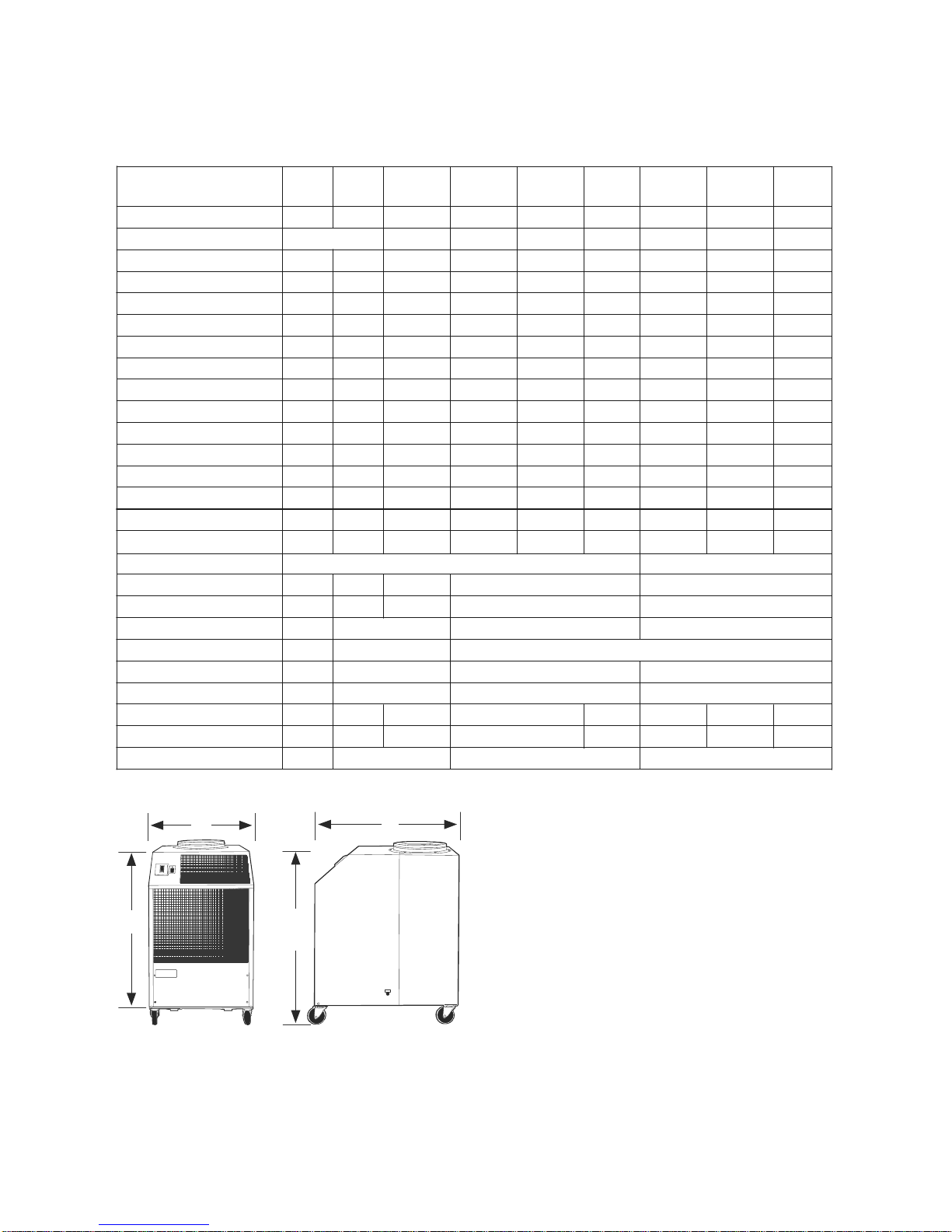
SPECIFICATIONS
1. Cooling Capacity is total BTUH at 80ºDB/67ºWB return air,
95ºF Outdoor at high fan speed
2. Time Delay fuses/circuit breakers are recommended
3. EER is determined at high fan speed, with condenser
discharge air ducted into another area
4. CFM with free discharge
5. Sound Pressure, dB at 5 feet, commercial operation
6. Amps & Watts at 208 Volts
May operate down to 55º if equipped with hot gas bypass
(Factory installed)
Ambient operating range 65º to 105º
50 Hz MODELS AVAILABLE - CONSULT FACTORY
Note: Condenser inlet air plenum adds
13 inches to dimension “C”
D
B
A
C

STANDARD FEATU RES
CABINET
The AirBoss Series cabinet is constructed of 18 gauge steel with a gray polyester powder
coated finish that will compliment any decor. The entire cabinet is insulated with a soundabsorbing insulation for cool, quiet comfort. All units come equipped with handles and
swivel casters for portability and convenient set-up.
ELECTRONIC THERMOSTAT
All Air Boss unit are equipped with a non-programmable electronic thermostat. When
power is connected to the unit, the thermostat will control the Air Boss to cool a space to
the desired temperature. The thermostat is also capable of controlling the fan to operate
automatically (when needed) or continuously. To protect the compressor from shortcycling, there is a built-in, 4-minute time delay in the thermostat.
FAN SPEED CONTROL
A two position rocker switch, located next to the thermostat, provides the user with the
option of running the evaporator fan in high-speed or low-speed.
CONDENSATE RESERVOIR/PUMP
Air Boss units come equipped with a means for handling the condensate generated dur-
ing the cooling process. All models except the 5-ton models come equipped with a
Condensate Reservoir Tank, that captures the condensate from cooling. The tank can
then be easily removed from the unit and emptied as required.
The 5-ton Air Boss models come equipped with an Automatic Condensate Pump that
disposes of the condensate. The pump comes with a 25 foot long vinyl hose that allows
for the disposal of the condensate water to a drain. The automatic pump is capable of a
20ft lift, to handle just about any installation requirement.
CONDENSATE ALARM LIGHT
On the front of all Air Boss models, there is a Condensate Alarm Light (RED) located near
the thermostat. For models less than 5-tons, the light indicates that the condensate tank
is full and needs to be emptied. In the 5-ton Air Boss units (model PAC60) the light indicates a condensate pump over-flow condition where the pump is either disabled, or incapable of rejecting the condensate water, and must be serviced.
FILTERS
All Air Boss units are equipped with washable filters at the air intakes. 1/8” mesh air filters
located behind the evaporator return air grill serve to filter the air before it is cooled. A
1/2” aluminum mesh filter serves to protect the condenser coil from dust build-up. Both
filters can be easily removed and cleaned.
HIGH PRESSURE SAFETY SWITCH
Located on the back of the Air Boss unit is a manual re-set high pressure switch, used for
the protection of the compressor. If the condensing pressure exceeds the limit setting, the
cut-out shuts down the compressor, while the evaporator fan remains running. The compressor can be re-started, once the condensing pressure has lowered, by depressing the
“RESET” button.
POWER CORDS
All Air boss units come with power cords, convenient connection and portability. All units
except the 5-ton models, and 3-phase models are equipped with LCDI for added safety
devices.
3
4
APPLICATIONS
SPOT COOLER
The Air Boss can be used in an open environment to cool specific objects or "spots".
Spot Cooling is a convenient and economical way to provide air conditioning where
cooling the entire space is impractical. Cool air is discharged from the unit and is directed
where it is needed. Nozzle kits can be used to improve direction of the cooling airflow.
AREA COOLER
When the Air Boss is installed in an area that is not totally enclosed, the condenser hot air
exhaust duct directs condenser air out of the area, allowing the evaporator air to cool the
specific space.
ROOM AIR CONDITIONER
When ducted, the OceanAire AirBoss can be used as a room air conditioner to cool an
enclosed space. Using the condenser return air plenum (DCP) and ceiling discharge kit
(CK) and ceiling panel kits CK-PL accessories, the Air Boss can operate as a room air
conditioner with the condenser air isolated form the conditioned space.
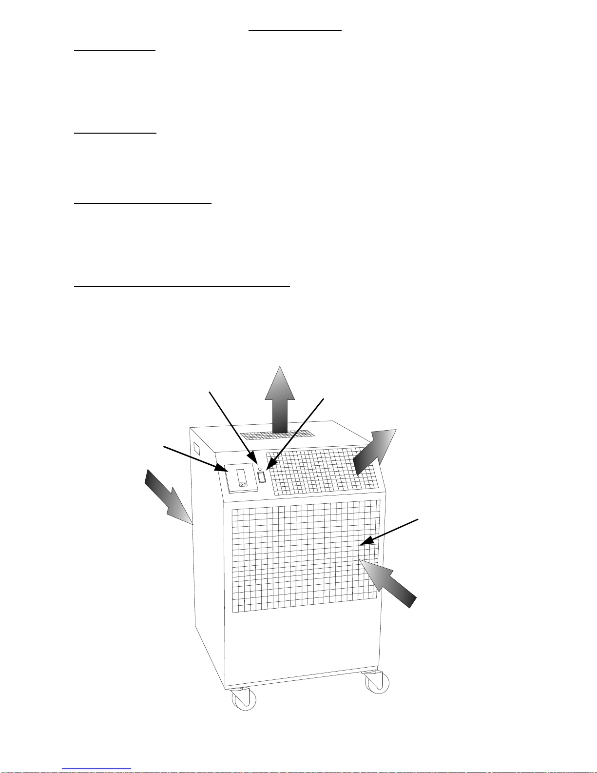
AIR BOSS—OPERATION / DESCRIPT ION
CONDENSER
AIR INLET
(Back of Unit)
CONDENSER FAN DISCHARGE
“HOT”
EVAPORATOR
FAN DISCHARGE
“COOL”
RETURN AIR
GRILL
AND FILTER
CONDENSATE
ALARM LIGHT
FAN SPEED
SWITCH
ELECTRONIC
THERMOSTAT
AIR BOSS—FRONT VIEW
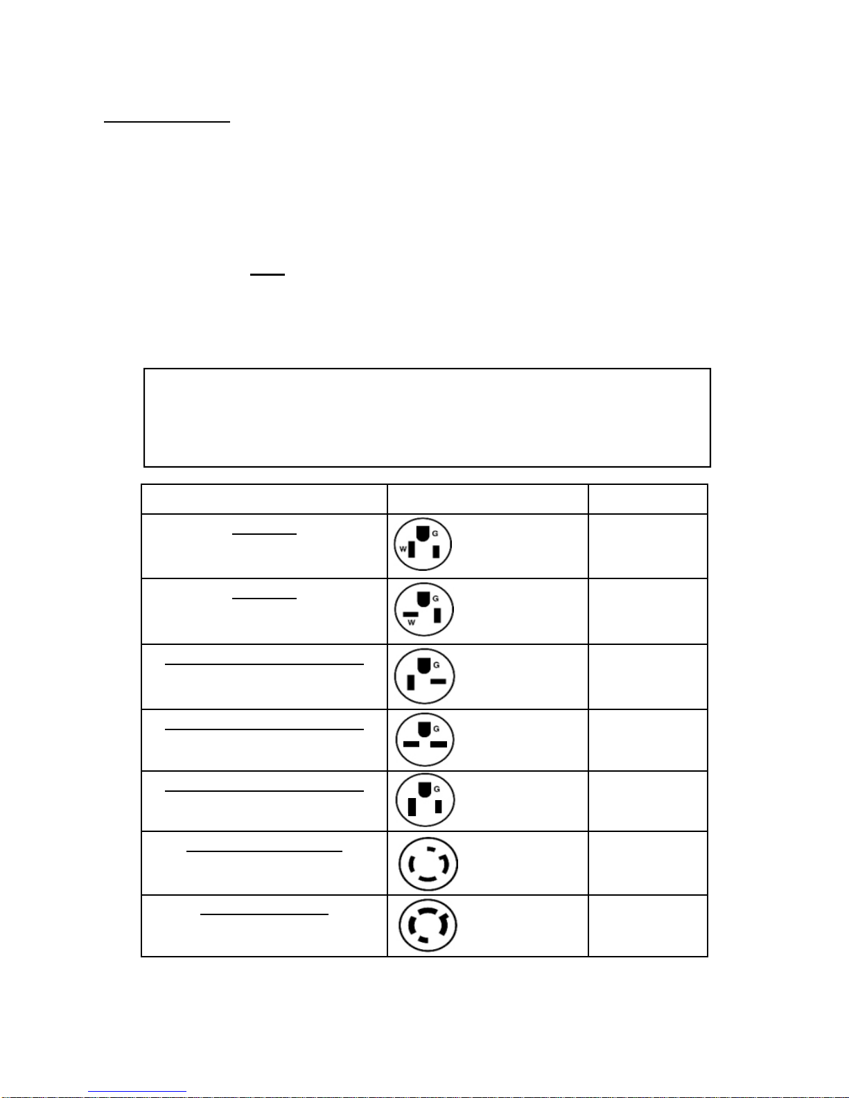
SERVICE CORD
All AirBoss Series units are equipped with the standard ten foot long service cord with
plug configurations and receptacle requirements as shown in this chart. PAC1211,
PAC1811, PAC2412 and PAC3612 units come with LCDI (Leakage Current Detection
& Interruption) devices that serve as a means of electrical protection.
CAUTION—DO NOT
USE THE LCDI AS AN ON/OFF SWITCH FOR THE UNIT
All 3-phase models are equipped with locking plugs for added connection reliability.
Refer to the chart below for plug and receptacle details for all Air Boss models.
A DAMAGED LCDI POWER SUPPLY CORD MUST BE
REPLACED WITH A NEW POWER SUPPLY CORD
OBTAINED FROM OCEANAIRE, AND NOT REPAIRED
UNIT/MODEL PLUG CONFIGURATION RECEPTACLE
115 VOLT
PAC1211
115 VOLT
PAC1811
208-230 VOLT SINGLE PHASE
PAC2412
208-230 VOLT SINGLE PHASE
PAC3612
208-230 VOLT SINGLE PHASE
PAC6012
208-230 VOLT 3-PHASE
PAC3632
PAC6032
460 VOLT 3-PHASE
PAC3634
PAC6034
15A-125 VOLT
NEMA 5-15P
20A-125 VOLT
NEMA 5-20P
20A-250 VOLT
NEMA 6-20P
30A-250 VOLT
NEMA 6-30P
50A-250 VOLT
NEMA 6-50P
30A-250 VOLT
NEMA L15-30P
20A-460 VOLT
NEMA L16-20P
NEMA-5-15R
NEMA 5-20R
NEMA 6-20R
NEMA 6-30R
NEMA 6-50R
NEMA L15-30R
NEMA L16-20R
5
6
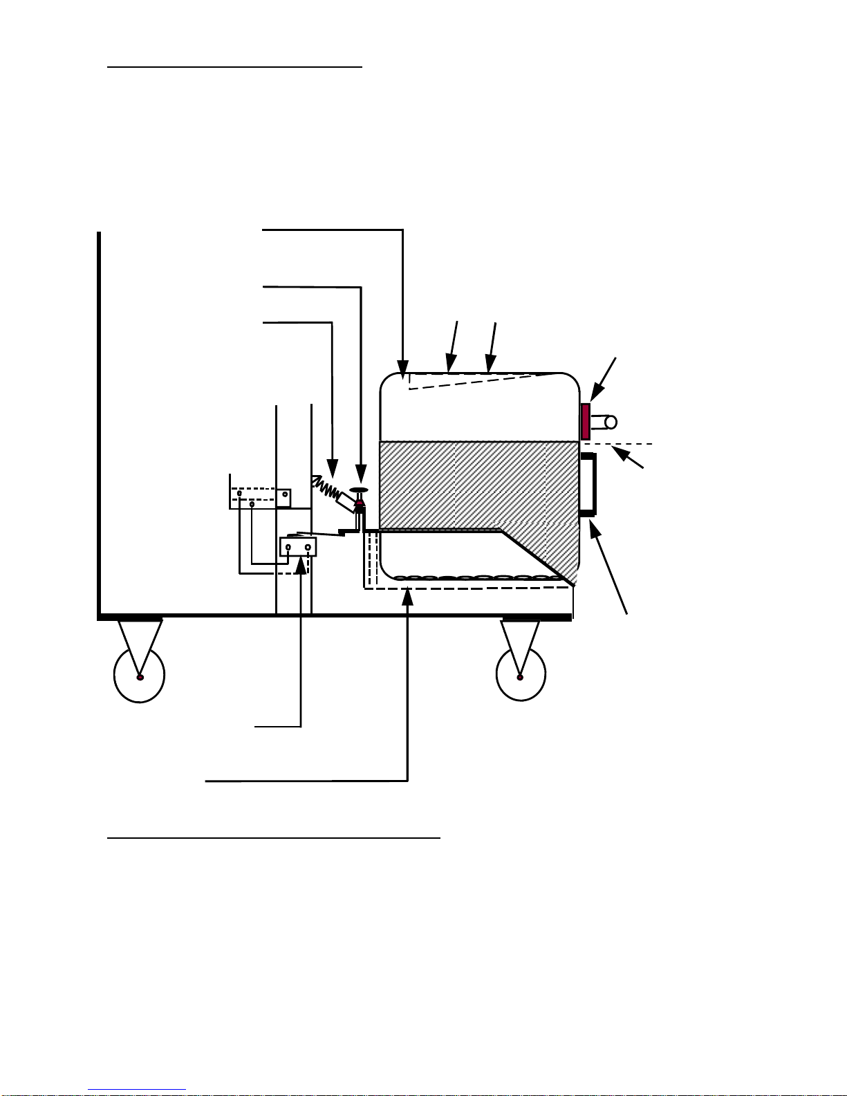
CONDENSATE RESERVOIR TANK
For Air Boss Models PAC12, PAC18, PAC24 and PAC36, a 5-gallon polyethylene tank is
provided standard, to collect condensate. The tank is located in the lower, front section
of the unit. A high water level cut-out switch is used to stop the compressor and
condenser fan automatically when the tank's pre-set water level has been reached. The
evaporator fan will continue to run, circulating air.
TANK LEVEL ADJUSTMENT INSTRUCTIONS
An adjustment screw is provided to vary the cut-off of the tank full switch. If a lighter (less
weight) level of water is desired, turn the adjusting screw clockwise. Do not exceed 6 full
turns counter-clockwise.
CAUTION, TURN UNIT OFF: BEFORE ADJUSTING SET SCREW
BEFORE REMOVING TANK TO EMPTY CONDENSATE
Turn screw clockwise to lower water level. Less water makes tank lighter and easier to
remove.
NOTE: Max. and Min. water levels shown are those at which the unit will shutdown and
not restart until the condensate tank has been drained.
Condensate Tank
*Tank Water Level
Adjusting Screw
Spring
Handle
For PAC36 —
Condensate
drains
through a
corrugated
hose into
tank cap
High Water Level
Cut-Out Switch
Condensate
Tank Tray
Max W ater
Level
4" From Top
For PAC12, PAC18
and PAC24 —
Condensate water
drops from drain pan
into trough on tank
7
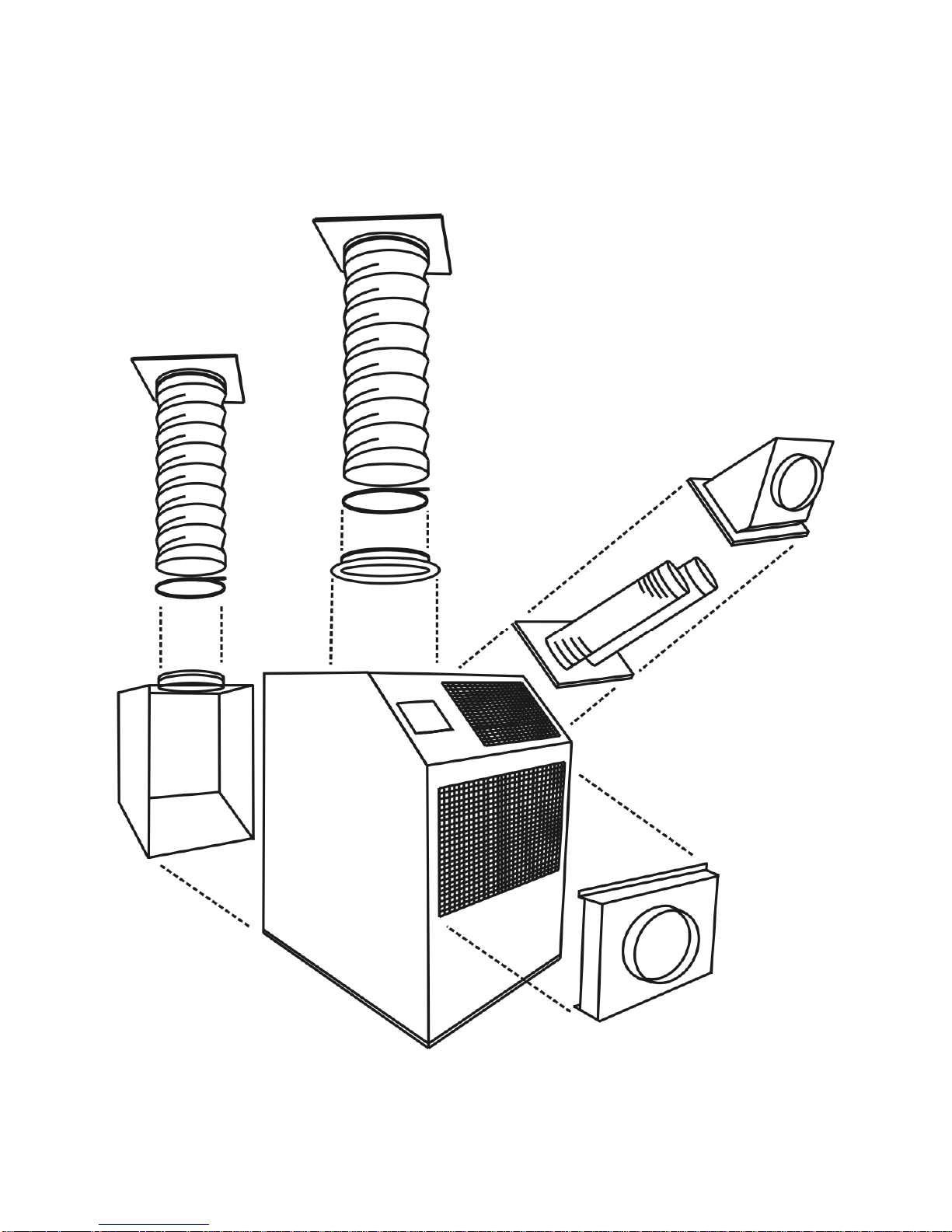
CK-12PL
(2 Req’d for
2DCP-4
CK-12
CK-16
2DDA-6
2DDA-10
2DDA-16
2NK-1
2NK-2
2NK-3
DEP-10
2DEP-12
DEP-16
2DCP-1
2DCP-2
2DCP-4
AIR BOSS UNIT
ACCESSORIES
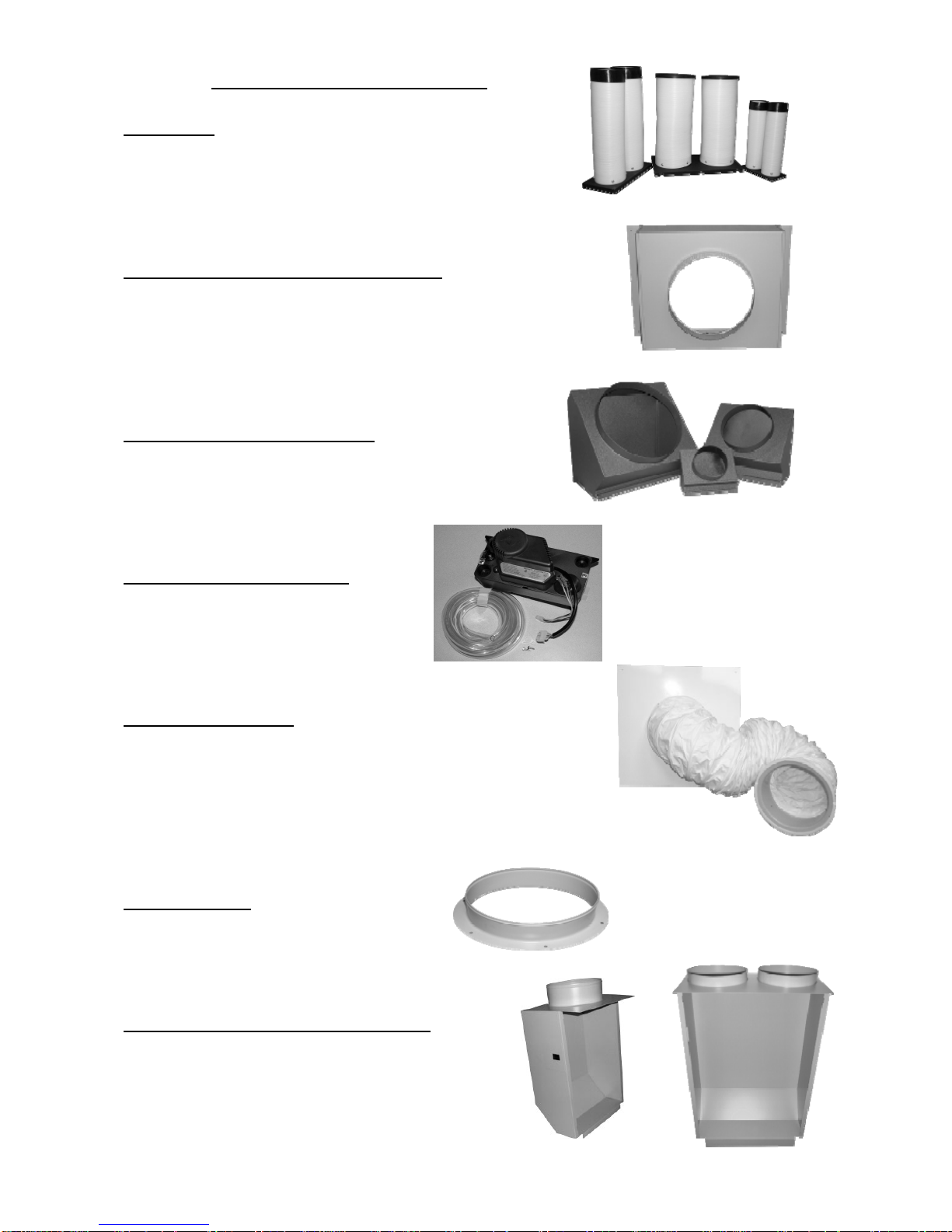
PAC – AIR BOSS ACCESSORIES
NOZZLE KIT
2NK-1 (2 X 4-Inch) PAC12
2NK-2 (2 X 6-Inch) PAC18, 24
2NK-3 (2 X 8-Inch) PAC36, 60
EVAPORATOR RETURN AIR PLENUM
DEP-10 (10-Inch Round) PAC12
2DEP-12 (12-Inch Round) PAC18, 24
DEP-16 (16-Inch Round) PAC36, 60
DISCHARGE DUCT ADAPTER
2DDA-6 (6-Inch Round) PAC12
2DDA-10 (10-Inch Round) PAC18, 24
DDA-16 (16-Inch Round) PAC36, 60
CONDENSATE PUMP KIT *
PC-1P 115V Models
PC-2P 230V Models
* Not Required for PAC60’s
CEILING PANEL KIT
CK-12 PAC12, 18, 24
CK-16 PAC36, 60
CK-12PL CK-12 without Duct Flange
CKP-12 2 X 2 Ceiling Panel w/12-Inch Dia. Flange
CKP-16 2 X 2 Ceiling Panel w/16-Inch Dia. Flange
DUCT FLANGE
DF-12 12-Inch Duct Flange
DF-16 16-Inch Duct Flange
CONDENSER RETURN AIR PLENUM
2DPC-1 PAC12
2DCP-2 PAC18, 24
2DCP-4 PAC60
8
 Loading...