


Océ User manual
Océ VarioStream 8000
Continuous Printing System

Océ Printing Systems GmbH
Copyright
Copyright
Copyright
All rights reserved, including rights of translation, reprinting, reproduction by
copying or any other method, of this document as a whole or parts thereof.
Offenders will be liable for damages.
All rights, including rights created b y patent grant or registration of a utility model
or design, are reserved.
Delivery subject to availability; right of technical modifications reserved.
Trademark protection
The designations Océ ColorStream
Web Buffer
TonerSafe
All hardware and software names used are trademarks of their respective owners.
©
2004 - 2008 Océ
®
, Océ VarioStream®, Océ VarioPrint®, Océ
®
, Océ PRISMA®production, Océ CustomTone®, and Océ
TM
are protected by trademark.
Training
We also offer courses in our Training Center for Océ VarioStream 8000.
Information:
Phone +49 8121 72 3940
Fax +49 8121 72 3950
Océ Printing Systems GmbH
ITC
Postfach 1260
85581 Poing
Germany
Order number A29246-X29-X-5-7680
Edition 2008-05
US

Table of Contents
Table of Contents
Chapter 1
Notes on printing system documentation. . . . . . . . . . . . . . . . . . . . . . . . . . . . . . 11
Notes on documentation for the printing system — overview . . . . . . . . . 12
Documentation signposts. . . . . . . . . . . . . . . . . . . . . . . . . . . . . . . . . . . . . 13
Notes on Help . . . . . . . . . . . . . . . . . . . . . . . . . . . . . . . . . . . . . . . . . . . . . 15
Notes on the Help - Overview. . . . . . . . . . . . . . . . . . . . . . . . . . . . . . . 15
Opening Help . . . . . . . . . . . . . . . . . . . . . . . . . . . . . . . . . . . . . . . . . . . 16
Navigating in Help. . . . . . . . . . . . . . . . . . . . . . . . . . . . . . . . . . . . . . . . 18
Contents. . . . . . . . . . . . . . . . . . . . . . . . . . . . . . . . . . . . . . . . . . . . . 18
Index . . . . . . . . . . . . . . . . . . . . . . . . . . . . . . . . . . . . . . . . . . . . . . . 19
Search . . . . . . . . . . . . . . . . . . . . . . . . . . . . . . . . . . . . . . . . . . . . . . 20
Opening Direct Help . . . . . . . . . . . . . . . . . . . . . . . . . . . . . . . . . . . . . . 21
Symbol conventions. . . . . . . . . . . . . . . . . . . . . . . . . . . . . . . . . . . . . . . . . 24
Symbols in the text . . . . . . . . . . . . . . . . . . . . . . . . . . . . . . . . . . . . . . . 24
Symbols in illustrations . . . . . . . . . . . . . . . . . . . . . . . . . . . . . . . . . . . . 25
Other documents . . . . . . . . . . . . . . . . . . . . . . . . . . . . . . . . . . . . . . . . . . . 26
Manufacturer of the printing system. . . . . . . . . . . . . . . . . . . . . . . . . . . . . 27
Statutory requirements. . . . . . . . . . . . . . . . . . . . . . . . . . . . . . . . . . . . . . . 28
Chapter 2
Security . . . . . . . . . . . . . . . . . . . . . . . . . . . . . . . . . . . . . . . . . . . . . . . . . . . . . . . . . 29
Security — overview . . . . . . . . . . . . . . . . . . . . . . . . . . . . . . . . . . . . . . . . 30
Intended Purpose . . . . . . . . . . . . . . . . . . . . . . . . . . . . . . . . . . . . . . . . . . 31
Flagging of safety directives . . . . . . . . . . . . . . . . . . . . . . . . . . . . . . . . . . 32
Warning and information signs . . . . . . . . . . . . . . . . . . . . . . . . . . . . . . . . 33
Accident and damage prevention . . . . . . . . . . . . . . . . . . . . . . . . . . . . . . 35
Accident and damage prevention — overview . . . . . . . . . . . . . . . . . . 35
Personal Representations. . . . . . . . . . . . . . . . . . . . . . . . . . . . . . . . . . 36
Operation . . . . . . . . . . . . . . . . . . . . . . . . . . . . . . . . . . . . . . . . . . . . . . 37
Transportation, assembly and installation, repair . . . . . . . . . . . . . . . . 40
Fire, disposal. . . . . . . . . . . . . . . . . . . . . . . . . . . . . . . . . . . . . . . . . . . . 41
Safety regulations and standards . . . . . . . . . . . . . . . . . . . . . . . . . . . . . . 42
Safety regulations and standards — overview . . . . . . . . . . . . . . . . . . 42
CE Mark . . . . . . . . . . . . . . . . . . . . . . . . . . . . . . . . . . . . . . . . . . . . . . . 44
Chapter 3
Description of the printing system . . . . . . . . . . . . . . . . . . . . . . . . . . . . . . . . . . . 45
Description of the printing system — overview . . . . . . . . . . . . . . . . . . . . 46
Device overview. . . . . . . . . . . . . . . . . . . . . . . . . . . . . . . . . . . . . . . . . . . . 47
Equipment - overview . . . . . . . . . . . . . . . . . . . . . . . . . . . . . . . . . . . . . 47
3

Table of Contents
Front view of the printing system. . . . . . . . . . . . . . . . . . . . . . . . . . . . . 48
Rear view of the printing system and main switch . . . . . . . . . . . . . . . 50
Operating elements . . . . . . . . . . . . . . . . . . . . . . . . . . . . . . . . . . . . . . . . . 52
Operating elements - overview . . . . . . . . . . . . . . . . . . . . . . . . . . . . . . 52
Key control panel on the paper transporter. . . . . . . . . . . . . . . . . . . . . 53
Additional operator panel . . . . . . . . . . . . . . . . . . . . . . . . . . . . . . . . . . 54
Operator Attention Light (OPAL) (optional) . . . . . . . . . . . . . . . . . . . . 57
Operating elements in the printing system . . . . . . . . . . . . . . . . . . . . . 59
Paper specifications. . . . . . . . . . . . . . . . . . . . . . . . . . . . . . . . . . . . . . . . . 60
Paper feed options. . . . . . . . . . . . . . . . . . . . . . . . . . . . . . . . . . . . . . . . . . 62
Chapter 4
Operator panel description. . . . . . . . . . . . . . . . . . . . . . . . . . . . . . . . . . . . . . . . . . 65
Description of the Operator Panel — Overview . . . . . . . . . . . . . . . . . . . . 66
Toolbar. . . . . . . . . . . . . . . . . . . . . . . . . . . . . . . . . . . . . . . . . . . . . . . . . . . 67
Toolbar - overview. . . . . . . . . . . . . . . . . . . . . . . . . . . . . . . . . . . . . . . . 67
Buttons and displays in the left-hand area . . . . . . . . . . . . . . . . . . . . . 68
Buttons and displays in the center area . . . . . . . . . . . . . . . . . . . . . . . 70
Frame toolbar . . . . . . . . . . . . . . . . . . . . . . . . . . . . . . . . . . . . . . . . . . . 74
Menu tree. . . . . . . . . . . . . . . . . . . . . . . . . . . . . . . . . . . . . . . . . . . . . . . . . 75
Menu tree — overview . . . . . . . . . . . . . . . . . . . . . . . . . . . . . . . . . . . . 75
'General' menus . . . . . . . . . . . . . . . . . . . . . . . . . . . . . . . . . . . . . . . . . 77
'General' menus — overview . . . . . . . . . . . . . . . . . . . . . . . . . . . . . 77
'User management' menus. . . . . . . . . . . . . . . . . . . . . . . . . . . . . . . 78
'User' menus. . . . . . . . . . . . . . . . . . . . . . . . . . . . . . . . . . . . . . . . . . 79
'Security' menus . . . . . . . . . . . . . . . . . . . . . . . . . . . . . . . . . . . . . . . 80
VarioStream menus. . . . . . . . . . . . . . . . . . . . . . . . . . . . . . . . . . . . . . . 81
'VarioStream' menus — overview. . . . . . . . . . . . . . . . . . . . . . . . . . 81
'Displays' menus. . . . . . . . . . . . . . . . . . . . . . . . . . . . . . . . . . . . . . . 83
'Configuration' menus. . . . . . . . . . . . . . . . . . . . . . . . . . . . . . . . . . . 84
'Setup' menus. . . . . . . . . . . . . . . . . . . . . . . . . . . . . . . . . . . . . . . . . 85
'Replace consumables ' me nu s. . . . . . . . . . . . . . . . . . . . . . . . . . . . 86
Menu display . . . . . . . . . . . . . . . . . . . . . . . . . . . . . . . . . . . . . . . . . . . . . . 88
Chapter 5
Working with the operator panel . . . . . . . . . . . . . . . . . . . . . . . . . . . . . . . . . . . . . 89
Working with the operator panel — overview. . . . . . . . . . . . . . . . . . . . . . 90
Managing user settings (Key Operator) . . . . . . . . . . . . . . . . . . . . . . . . . . 91
Manage user settings (Key Operator) — overview . . . . . . . . . . . . . . . 91
Advanced password protection (optional extra for the Variostream 9000)
. . . . . . . . . . . . . . . . . . . . . . . . . . . . . . . . . . . . . . . . . . . . . . . . . . . . . . 93
'Add user'. . . . . . . . . . . . . . . . . . . . . . . . . . . . . . . . . . . . . . . . . . . . . . . 94
'Delete user'. . . . . . . . . . . . . . . . . . . . . . . . . . . . . . . . . . . . . . . . . . . . . 95
Setting password/'General' tab . . . . . . . . . . . . . . . . . . . . . . . . . . . . . . 96
Releasing and blocking menus and elements/'User rights' tab. . . . . . 97
4

Table of Contents
Setting language/'User profile' tab . . . . . . . . . . . . . . . . . . . . . . . . . . . 98
Managing user settings (Operator) . . . . . . . . . . . . . . . . . . . . . . . . . . . . . 99
Manage user settings (Operator) — overview . . . . . . . . . . . . . . . . . . 99
Log on as user and request an access ticket . . . . . . . . . . . . . . . . . . 100
Changing password/'Password' tab . . . . . . . . . . . . . . . . . . . . . . . . . 101
Changing language/'User profile' tab . . . . . . . . . . . . . . . . . . . . . . . . 102
Log off as user . . . . . . . . . . . . . . . . . . . . . . . . . . . . . . . . . . . . . . . . . 103
Selecting settings and entering values . . . . . . . . . . . . . . . . . . . . . . . . . 104
Applying or resetting settings. . . . . . . . . . . . . . . . . . . . . . . . . . . . . . . . . 105
Configuring operation mode. . . . . . . . . . . . . . . . . . . . . . . . . . . . . . . . . . 106
Working with setups. . . . . . . . . . . . . . . . . . . . . . . . . . . . . . . . . . . . . . . . 107
Working with setups — overview . . . . . . . . . . . . . . . . . . . . . . . . . . . 107
Creating a new setup or changing a setup . . . . . . . . . . . . . . . . . . . . 108
Importing a setup . . . . . . . . . . . . . . . . . . . . . . . . . . . . . . . . . . . . . . . 110
Exporting a setup . . . . . . . . . . . . . . . . . . . . . . . . . . . . . . . . . . . . . . . 112
Managing resources . . . . . . . . . . . . . . . . . . . . . . . . . . . . . . . . . . . . . . . 114
Managing resources — overview . . . . . . . . . . . . . . . . . . . . . . . . . . . 114
Resource installation. . . . . . . . . . . . . . . . . . . . . . . . . . . . . . . . . . . . . 115
Delete resources. . . . . . . . . . . . . . . . . . . . . . . . . . . . . . . . . . . . . . . . 116
Editing 'Replace consumables' menus on the operator panel . . . . . . . . 117
Chapter 6
Operating the printing system . . . . . . . . . . . . . . . . . . . . . . . . . . . . . . . . . . . . . . 121
Operating the printing system — overview . . . . . . . . . . . . . . . . . . . . . . 122
Powering on the printing system . . . . . . . . . . . . . . . . . . . . . . . . . . . . . . 123
After printing has stopped, switch the printing system back to 'Ready' . 125
Inserting the paper web on single printing systems. . . . . . . . . . . . . . . . 126
Inserting the paper web on single printing systems - overview. . . . . 126
Preparing to insert the paper web. . . . . . . . . . . . . . . . . . . . . . . . . . . 127
Preparing to insert the paper web - overview. . . . . . . . . . . . . . . . 127
Stopping the printing system and opening the doors. . . . . . . . . . 128
Preparing the paper transporter. . . . . . . . . . . . . . . . . . . . . . . . . . 129
Preparing the paper web . . . . . . . . . . . . . . . . . . . . . . . . . . . . . . . 132
Inserting the paper web. . . . . . . . . . . . . . . . . . . . . . . . . . . . . . . . . . . 133
Inserting the paper web - overview . . . . . . . . . . . . . . . . . . . . . . . 133
Inserting paper web in paper input. . . . . . . . . . . . . . . . . . . . . . . . 134
Inserting paper web in vacuum box and paper transporter . . . . . 136
Completing the insertion of the paper web . . . . . . . . . . . . . . . . . . . . 140
Completing the insertion of the paper web - overview . . . . . . . . . 140
Close flaps, units, etc. . . . . . . . . . . . . . . . . . . . . . . . . . . . . . . . . . 141
Settings for different paper properties . . . . . . . . . . . . . . . . . . . . . 143
After inserting the paper web. . . . . . . . . . . . . . . . . . . . . . . . . . . . 147
Inserting the paper web in twin and triplex printing systems . . . . . . . . . 148
Inserting the paper web in twin and triplex printing systems - overview .
. . . . . . . . . . . . . . . . . . . . . . . . . . . . . . . . . . . . . . . . . . . . . . . . . . . . . 148
5

Table of Contents
Preparing to insert the paper web on twin or triplex printing systems 149
Paper guide in the inline turn bar . . . . . . . . . . . . . . . . . . . . . . . . . . . 150
Paper guide in the turning platform. . . . . . . . . . . . . . . . . . . . . . . . . . 156
Synchronization and positioning . . . . . . . . . . . . . . . . . . . . . . . . . . . . . . 163
Synchronization and positioning - overview . . . . . . . . . . . . . . . . . . . 163
Synchronization - Page integrity marks (PIM) for perforated paper . 164
Synchronization - Barcode synchronization mark for unperforated paper
. . . . . . . . . . . . . . . . . . . . . . . . . . . . . . . . . . . . . . . . . . . . . . . . . . . . . 166
Positioning mark sensor. . . . . . . . . . . . . . . . . . . . . . . . . . . . . . . . . . . . . 171
Positioning mark sensors - overview. . . . . . . . . . . . . . . . . . . . . . . . . 171
Positioning upper mark sensor . . . . . . . . . . . . . . . . . . . . . . . . . . . . . 172
Positioning lower mark sensor . . . . . . . . . . . . . . . . . . . . . . . . . . . . . 173
Calibrating mark sensor. . . . . . . . . . . . . . . . . . . . . . . . . . . . . . . . . . . . . 176
Calibrating mark sensor - overview. . . . . . . . . . . . . . . . . . . . . . . . . . 176
Calibrating upper mark sensor . . . . . . . . . . . . . . . . . . . . . . . . . . . . . 177
Calibrate lower mark sensor . . . . . . . . . . . . . . . . . . . . . . . . . . . . . . . 179
Paper change settings on the printing system. . . . . . . . . . . . . . . . . . . . 181
Paper change settings on the printing system - overview. . . . . . . . . 181
Possible dirt after paper change . . . . . . . . . . . . . . . . . . . . . . . . . . . . 182
Set rear paper web guide . . . . . . . . . . . . . . . . . . . . . . . . . . . . . . . . . 183
Set pressure roller. . . . . . . . . . . . . . . . . . . . . . . . . . . . . . . . . . . . . . . 184
Set loop puller force . . . . . . . . . . . . . . . . . . . . . . . . . . . . . . . . . . . . . 186
Setting the position of the brake roller. . . . . . . . . . . . . . . . . . . . . . . . 187
Paper change settings on the operator panel . . . . . . . . . . . . . . . . . . . . 194
Paper change settings on the operator panel - overview . . . . . . . . . 194
Settings on the operator panel: 'Setup' . . . . . . . . . . . . . . . . . . . . . . 195
Settings on the operator panel: Paper with/without perforation. . . . . 196
Settings on the operator panel: Paper dimensions . . . . . . . . . . . . . . 197
Settings on the operator panel: Paper brake. . . . . . . . . . . . . . . . . . . 198
Settings on the operator panel: Fusing . . . . . . . . . . . . . . . . . . . . . . . 199
Synchronized roll change during a print job (twin/triplex). . . . . . . . . . . . 200
Replacing paper roll during a print job (twin/triplex) - overview. . . . . 200
Automatic start of roll replacement . . . . . . . . . . . . . . . . . . . . . . . . . . 201
Manual roll replacement before paper end or without external paper end
Paper guide in the inline turn bar - overview . . . . . . . . . . . . . . . . 150
Paper guide for reverse-side printing . . . . . . . . . . . . . . . . . . . . . . 151
Paper guide for front-side printing . . . . . . . . . . . . . . . . . . . . . . . . 154
Changing paper width in the inline turn bar . . . . . . . . . . . . . . . . . 155
Paper guide in the turning platform - overview. . . . . . . . . . . . . . . 156
Paper guide for reverse-side printing . . . . . . . . . . . . . . . . . . . . . . 157
Paper guide for front-side printing . . . . . . . . . . . . . . . . . . . . . . . . 160
Setting the position of the brake roller - overview. . . . . . . . . . . . . 187
Paper web runs to the rear in the printer . . . . . . . . . . . . . . . . . . . 188
Paper web runs to the front in the printer. . . . . . . . . . . . . . . . . . . 190
The brake roller setting has been lost . . . . . . . . . . . . . . . . . . . . . 192
6

Table of Contents
light barrier . . . . . . . . . . . . . . . . . . . . . . . . . . . . . . . . . . . . . . . . . . . . 203
Activate/deactivate function 'Automatic start' . . . . . . . . . . . . . . . . . . 204
Affixing the paper web. . . . . . . . . . . . . . . . . . . . . . . . . . . . . . . . . . . . 205
Printing with another color . . . . . . . . . . . . . . . . . . . . . . . . . . . . . . . . . . . 209
Printing with another color - overview. . . . . . . . . . . . . . . . . . . . . . . . 209
Replacing the toner feed. . . . . . . . . . . . . . . . . . . . . . . . . . . . . . . . . . 210
Replacing the toner feed - overview. . . . . . . . . . . . . . . . . . . . . . . 210
Removing toner feed . . . . . . . . . . . . . . . . . . . . . . . . . . . . . . . . . . 211
Installing toner feed . . . . . . . . . . . . . . . . . . . . . . . . . . . . . . . . . . . 214
Replacing the developer station . . . . . . . . . . . . . . . . . . . . . . . . . . . . 217
Replacing the developer station — overview. . . . . . . . . . . . . . . . 217
Preparations for removing the developer station . . . . . . . . . . . . . 219
Removing the developer station. . . . . . . . . . . . . . . . . . . . . . . . . . 222
Final tasks for removing the developer station. . . . . . . . . . . . . . . 226
Preparations for installing the developer station . . . . . . . . . . . . . 228
Installing the developer station. . . . . . . . . . . . . . . . . . . . . . . . . . . 230
Final tasks for installing the developer station . . . . . . . . . . . . . . . 234
Converting the printing system . . . . . . . . . . . . . . . . . . . . . . . . . . . . . . . 237
Converting the printing system - overview . . . . . . . . . . . . . . . . . . . . 237
Select configuration. . . . . . . . . . . . . . . . . . . . . . . . . . . . . . . . . . . . . . 239
Start conversion . . . . . . . . . . . . . . . . . . . . . . . . . . . . . . . . . . . . . . . . 240
Replacing the toner feed. . . . . . . . . . . . . . . . . . . . . . . . . . . . . . . . . . 241
Replacing developer station . . . . . . . . . . . . . . . . . . . . . . . . . . . . . . . 242
Changing the photoconductor drum . . . . . . . . . . . . . . . . . . . . . . . . . 243
Replace fuser roller. . . . . . . . . . . . . . . . . . . . . . . . . . . . . . . . . . . . . . 244
Complete conversion . . . . . . . . . . . . . . . . . . . . . . . . . . . . . . . . . . . . 245
Powering off the printing system . . . . . . . . . . . . . . . . . . . . . . . . . . . . . . 246
Chapter 7
Cleaning the printing system. . . . . . . . . . . . . . . . . . . . . . . . . . . . . . . . . . . . . . . 249
Cleaning the printing system — overview . . . . . . . . . . . . . . . . . . . . . . . 250
Cleaning agents and devices, cleaning intervals. . . . . . . . . . . . . . . . . . 252
Clean the paper path . . . . . . . . . . . . . . . . . . . . . . . . . . . . . . . . . . . . . . . 255
Clean transfer roller . . . . . . . . . . . . . . . . . . . . . . . . . . . . . . . . . . . . . . . . 261
Clean plastic strips. . . . . . . . . . . . . . . . . . . . . . . . . . . . . . . . . . . . . . . . . 262
Clean fuser station. . . . . . . . . . . . . . . . . . . . . . . . . . . . . . . . . . . . . . . . . 264
Clean soft fuser roller. . . . . . . . . . . . . . . . . . . . . . . . . . . . . . . . . . . . . . . 270
Clean the developer station. . . . . . . . . . . . . . . . . . . . . . . . . . . . . . . . . . 273
Cleaning the sensors. . . . . . . . . . . . . . . . . . . . . . . . . . . . . . . . . . . . . . . 277
Cleaning the sensors — overview. . . . . . . . . . . . . . . . . . . . . . . . . . . 277
Cleaning the toner mark sensor . . . . . . . . . . . . . . . . . . . . . . . . . . . . 278
Cleaning the toner dust sensor. . . . . . . . . . . . . . . . . . . . . . . . . . . . . 279
Cleaning the paper edge sensor in the fuser station. . . . . . . . . . . . . 281
Clean paper edge monitoring sensor (with inserted paper) . . . . . . . 283
Cleaning the toner suction system. . . . . . . . . . . . . . . . . . . . . . . . . . . . . 284
7

Table of Contents
Clean corotrons . . . . . . . . . . . . . . . . . . . . . . . . . . . . . . . . . . . . . . . . . . . 288
Clean LED print head. . . . . . . . . . . . . . . . . . . . . . . . . . . . . . . . . . . . . . . 289
Cleaning the filter. . . . . . . . . . . . . . . . . . . . . . . . . . . . . . . . . . . . . . . . . . 290
Clean screen . . . . . . . . . . . . . . . . . . . . . . . . . . . . . . . . . . . . . . . . . . . . . 293
Cleaning the printing system generally . . . . . . . . . . . . . . . . . . . . . . . . . 294
Chapter 8
Replacing consumables . . . . . . . . . . . . . . . . . . . . . . . . . . . . . . . . . . . . . . . . . . . 295
Replacing consumables — overview. . . . . . . . . . . . . . . . . . . . . . . . . . . 296
Order numbers and packaging units for consumables. . . . . . . . . . . . . . 297
Monthly requirement for consumables. . . . . . . . . . . . . . . . . . . . . . . . . . 299
Toner bottle identification with Océ TonerSafeTM. . . . . . . . . . . . . . . . . 302
Replacing the developer . . . . . . . . . . . . . . . . . . . . . . . . . . . . . . . . . . . . 306
Replacing the developer — overview . . . . . . . . . . . . . . . . . . . . . . . . 306
Empty developer station . . . . . . . . . . . . . . . . . . . . . . . . . . . . . . . . . . 308
Fill developer. . . . . . . . . . . . . . . . . . . . . . . . . . . . . . . . . . . . . . . . . . . 312
Completing the replacement of the developer. . . . . . . . . . . . . . . . . . 318
Replacing the fuser oil bottle . . . . . . . . . . . . . . . . . . . . . . . . . . . . . . . . . 319
Replacing the fuser oil bottle - overview . . . . . . . . . . . . . . . . . . . . . . 319
Removing the fuser oil bottle. . . . . . . . . . . . . . . . . . . . . . . . . . . . . . . 320
Inserting the fuser oil bottle. . . . . . . . . . . . . . . . . . . . . . . . . . . . . . . . 322
Replacing waste oil container . . . . . . . . . . . . . . . . . . . . . . . . . . . . . . . . 324
Replacing the waste oil container — overview . . . . . . . . . . . . . . . . . 324
Removing waste oil container . . . . . . . . . . . . . . . . . . . . . . . . . . . . . . 325
Installing waste oil container . . . . . . . . . . . . . . . . . . . . . . . . . . . . . . . 326
Change toner bottle . . . . . . . . . . . . . . . . . . . . . . . . . . . . . . . . . . . . . . . . 327
Filling toner box . . . . . . . . . . . . . . . . . . . . . . . . . . . . . . . . . . . . . . . . . . . 331
Replacing the waste toner bottle . . . . . . . . . . . . . . . . . . . . . . . . . . . . . . 332
Replacing the waste toner bottle - overview . . . . . . . . . . . . . . . . . . . 332
Removing the waste toner bottle. . . . . . . . . . . . . . . . . . . . . . . . . . . . 333
Inserting the waste toner bottle. . . . . . . . . . . . . . . . . . . . . . . . . . . . . 335
Chapter 9
Replacing expendables. . . . . . . . . . . . . . . . . . . . . . . . . . . . . . . . . . . . . . . . . . . . 337
Replacing expendables — overview . . . . . . . . . . . . . . . . . . . . . . . . . . . 338
Order numbers and packaging units for expendables . . . . . . . . . . . . . . 339
Monthly requirement for expendables . . . . . . . . . . . . . . . . . . . . . . . . . . 341
Replacing the active filter. . . . . . . . . . . . . . . . . . . . . . . . . . . . . . . . . . . . 345
Replacing the active filter - overview. . . . . . . . . . . . . . . . . . . . . . . . . 345
Remove active filter. . . . . . . . . . . . . . . . . . . . . . . . . . . . . . . . . . . . . . 346
Insert active filter. . . . . . . . . . . . . . . . . . . . . . . . . . . . . . . . . . . . . . . . 348
Replacing the pressure roller . . . . . . . . . . . . . . . . . . . . . . . . . . . . . . . . . 351
Replacing the pressure roller - overview. . . . . . . . . . . . . . . . . . . . . . 351
Remove pressure roller. . . . . . . . . . . . . . . . . . . . . . . . . . . . . . . . . . . 352
Install pressure roller. . . . . . . . . . . . . . . . . . . . . . . . . . . . . . . . . . . . . 356
8

Table of Contents
Replacing the corotron s. . . . . . . . . . . . . . . . . . . . . . . . . . . . . . . . . . . . . 360
Replacing the corotrons - overview. . . . . . . . . . . . . . . . . . . . . . . . . . 360
Preparing corotron replacement . . . . . . . . . . . . . . . . . . . . . . . . . . . . 361
Remove charge corotrons. . . . . . . . . . . . . . . . . . . . . . . . . . . . . . . . . 362
Install charge corotrons . . . . . . . . . . . . . . . . . . . . . . . . . . . . . . . . . . . 363
Remove torn charge corotron . . . . . . . . . . . . . . . . . . . . . . . . . . . . . . 364
Remove discharge corotrons . . . . . . . . . . . . . . . . . . . . . . . . . . . . . . 366
Install discharge corotrons . . . . . . . . . . . . . . . . . . . . . . . . . . . . . . . . 367
Remove torn discharge corotron. . . . . . . . . . . . . . . . . . . . . . . . . . . . 368
Complete corotron replacement . . . . . . . . . . . . . . . . . . . . . . . . . . . . 370
Replacing the heating element . . . . . . . . . . . . . . . . . . . . . . . . . . . . . . . 371
Replacing the heating element - overview . . . . . . . . . . . . . . . . . . . . 371
Remove heater . . . . . . . . . . . . . . . . . . . . . . . . . . . . . . . . . . . . . . . . . 372
Installing the heating element . . . . . . . . . . . . . . . . . . . . . . . . . . . . . . 376
Replacing the fine filter . . . . . . . . . . . . . . . . . . . . . . . . . . . . . . . . . . . . . 380
Replacing the fine filter - overview . . . . . . . . . . . . . . . . . . . . . . . . . . 380
Remove fine filter . . . . . . . . . . . . . . . . . . . . . . . . . . . . . . . . . . . . . . . 381
Install fine filter . . . . . . . . . . . . . . . . . . . . . . . . . . . . . . . . . . . . . . . . . 383
Replacing the fuser roller. . . . . . . . . . . . . . . . . . . . . . . . . . . . . . . . . . . . 385
Replacing the fuser roller - overview. . . . . . . . . . . . . . . . . . . . . . . . . 385
Preparing to replace the fuser roller and removing the heating element
. . . . . . . . . . . . . . . . . . . . . . . . . . . . . . . . . . . . . . . . . . . . . . . . . . . . . 386
Remove fuser roller. . . . . . . . . . . . . . . . . . . . . . . . . . . . . . . . . . . . . . 390
Install fuser roller. . . . . . . . . . . . . . . . . . . . . . . . . . . . . . . . . . . . . . . . 393
Installing the heating element and completing replacement of the fuser
roller . . . . . . . . . . . . . . . . . . . . . . . . . . . . . . . . . . . . . . . . . . . . . . . . . 395
Replacing the photoconductor drum . . . . . . . . . . . . . . . . . . . . . . . . . . . 399
Replacing the photoconductor drum - overview . . . . . . . . . . . . . . . . 399
Removing the photoconductor drum. . . . . . . . . . . . . . . . . . . . . . . . . 400
Install photoconductor drum . . . . . . . . . . . . . . . . . . . . . . . . . . . . . . . 403
Running in the photoconductor drum. . . . . . . . . . . . . . . . . . . . . . . . . . . 406
Replacing the cleaning brush. . . . . . . . . . . . . . . . . . . . . . . . . . . . . . . . . 407
Replacing the cleaning brush — overview . . . . . . . . . . . . . . . . . . . . 407
Remove cleaning brush . . . . . . . . . . . . . . . . . . . . . . . . . . . . . . . . . . 408
Inserting the cleaning brush . . . . . . . . . . . . . . . . . . . . . . . . . . . . . . . 411
Replacing the cleaning belt . . . . . . . . . . . . . . . . . . . . . . . . . . . . . . . . . . 413
Replacing the cleaning belt - overview . . . . . . . . . . . . . . . . . . . . . . . 413
Remove cleaning belt . . . . . . . . . . . . . . . . . . . . . . . . . . . . . . . . . . . . 414
Install cleaning belt . . . . . . . . . . . . . . . . . . . . . . . . . . . . . . . . . . . . . . 416
Replacing the transfer rol ler. . . . . . . . . . . . . . . . . . . . . . . . . . . . . . . . . . 418
Replace/clean transfer roller - overview . . . . . . . . . . . . . . . . . . . . . . 418
Remove transfer roller. . . . . . . . . . . . . . . . . . . . . . . . . . . . . . . . . . . . 419
Install transfer roller. . . . . . . . . . . . . . . . . . . . . . . . . . . . . . . . . . . . . . 421
Replacing the waste col l ec tor . . . . . . . . . . . . . . . . . . . . . . . . . . . . . . . . 423
Replacing the dirt bin - overview. . . . . . . . . . . . . . . . . . . . . . . . . . . . 423
9

Table of Contents
Remove dirt bin. . . . . . . . . . . . . . . . . . . . . . . . . . . . . . . . . . . . . . . . . 424
Install dirt bin. . . . . . . . . . . . . . . . . . . . . . . . . . . . . . . . . . . . . . . . . . . 426
Chapter 10
Correcting problems . . . . . . . . . . . . . . . . . . . . . . . . . . . . . . . . . . . . . . . . . . . . . . 429
Correcting problems — overview. . . . . . . . . . . . . . . . . . . . . . . . . . . . . . 430
Processing messages on the operator panel. . . . . . . . . . . . . . . . . . . . . 431
Permitting or blocking remote access . . . . . . . . . . . . . . . . . . . . . . . . . . 435
Correct fusing errors . . . . . . . . . . . . . . . . . . . . . . . . . . . . . . . . . . . . . . . 436
Clogged toner suction . . . . . . . . . . . . . . . . . . . . . . . . . . . . . . . . . . . . . . 437
Clogged toner suction - overview . . . . . . . . . . . . . . . . . . . . . . . . . . . 437
Vacuum out the toner feed . . . . . . . . . . . . . . . . . . . . . . . . . . . . . . . . 438
Remove toner from the clogged toner feed hose . . . . . . . . . . . . . . . 439
Substandard print quality . . . . . . . . . . . . . . . . . . . . . . . . . . . . . . . . . . . . 443
Substandard print quality - overview. . . . . . . . . . . . . . . . . . . . . . . . . 443
Substandard print quality Cause and correction . . . . . . . . . . . . . . . . 444
Chapter 11
Technical data . . . . . . . . . . . . . . . . . . . . . . . . . . . . . . . . . . . . . . . . . . . . . . . . . . . 447
Technical data - Overview . . . . . . . . . . . . . . . . . . . . . . . . . . . . . . . . . . . 448
Technology and printing speed . . . . . . . . . . . . . . . . . . . . . . . . . . . . . . . 449
Paper . . . . . . . . . . . . . . . . . . . . . . . . . . . . . . . . . . . . . . . . . . . . . . . . . . . 451
Electrical values. . . . . . . . . . . . . . . . . . . . . . . . . . . . . . . . . . . . . . . . . . . 452
Mechanical conditions . . . . . . . . . . . . . . . . . . . . . . . . . . . . . . . . . . . . . . 453
Environmental conditions. . . . . . . . . . . . . . . . . . . . . . . . . . . . . . . . . . . . 454
Appendix A
Your comments on this user guide . . . . . . . . . . . . . . . . . . . . . . . . . . . . . . . . . . 455
Your comments on this user guide. . . . . . . . . . . . . . . . . . . . . . . . . . . . . 456
10

Chapter 1
Notes on printing system
documentation
11

Notes on documentation for the printing system — overview
Notes on documentation for the printing system — o verview
Introduction
The purpose of this documentation is to ensure that all printing system-related work
is carried out safely and correctly. It contains safety directives that must be strictly
observed.
Each section is divided into small, easy-to-understand subject areas. Overviews at
the beginning of th e sections help you to f ind the precise information you are looking
for quickly.
Overview
Here, you will find information on the following topics:
■ Documentation signposts on page 13
■ Notes on the Help - Overview on page 15
■ Symbols in the text on page 24
■ Symbols in illustrations on page 25
■ Other documents on page 26
■ Manufacturer of the printing system on page 27
■ Statutory requirements on page 28
12 Chapter 1 Notes on printing system documentation

Documentation signposts
Introduction
Documentation available to you on the Océ VarioStream 8000 includes a printed
user guide and help on the operator panel. This help is updated with every new
version of the operator panel software.
Security
This section gives you all necessary information on how to safely and efficiently
operate the printing syst em.
Description of the printing system
This section shows the structure of the printing system, describes the operating
elements and explains the printing principle. Y ou will also f ind information on paper
types and how to handle the paper.
Documentation signposts
Operator panel description
This section describes the individual areas of the operator panel with the most
important menus, buttons and icons.
Working with the operator panel
This section explains how you manage all user settings, how you select or enter
parameters on the operator panel, how you collect special settings for frequently
recurring print jobs using setups, how you manage resources for printing operation
and how you replace consumables and expendables using the operator panel.
Operating the printing system
This section describes ho w to power the printing system on and of f and the procedure
for inserting, affixing and removing the paper web, and also contains all other
information that you will need to operate the printing system.
Cleaning the printing system
This section shows you how often to clean the different components and how to carry
out this cleaning.
13

Documentation signposts
Replacing consumables
This section describes in detail all the steps required to replace consumables. It also
provides the order numbers and package units for all consumables.
Replacing expendables
This section describes in detail all the steps required to replace expendables. It also
provides the order numbers and package units for all expendables.
Correcting errors
This section shows you how to locate and remedy errors using the messages
displayed on the operator panel. It also describes ho w you ca n enable remote access
to allow remote diagnosis by Service during print operation. You will also find
information on how to correct any fusing errors.
Technical data
This section contains the most important technical data for the printing system.
You can use the ruler for controlling the paper path synchronization to assign the
marks on the paper input to certain form lengths.
14 Chapter 1 Notes on printing system documentation

Notes on Help
Notes on the Help - Overview
Introduction
This section shows you how you can quickly and easily access the information that
you currently require for your wo rk with the printing system.
There are two ways you can access help topics:
■ Help button on the toolbar and subsequent navigation via contents, index or
search
■ Direct Help via the F1 key
Overview
Notes on the Help - Overview
Here, you will find information on the following topics:
■ Opening Help on page 16
■ Opening Direct Help on page 21
Navigating in the Help:
■ Contents on page 18
■ Index on page 19
■ Search on page 20
Symbol conventions
■ Symbols in the text on page 24
■ Symbols in illustrations on page 25
15

Opening Help
Opening Help
To open Help
[1]
Proceed as follows:
1. Click on the following button in the frame toolbar:
[1]
The Help window opens. The navigation area is displayed initially:
[2]
The width of the navigation area can be changed with the mouse.
16 Chapter 1 Notes on printing system documentation

Function of the buttons in the Help window
[2]
Button Function
[3]
Hides or displays the navigation area with the following tabs:
[4]
■ Contents on page 18
■ Index on page 19
■ Search on page 20
When the navigation area is hidden, more space is available to
view the help topics.
[5]
Switches between the last help topics (backwards or forwards).
[6]
Switches from any help topic directly to the Help start page.
[7]
Closes Help.
Opening Help
17

Contents
Navigating in Help
Contents
Structuring in main groups
The Help is divided into separate main groups:
■ 'General'
■ 'VarioStream'
■ 'Paperpath Manager'
■ Any devices for paper post-print processing
To call up Help topics via the contents
[3]
Proceed as follows:
1. Click on the 'Contents' tab.
2. Click on the buttons for specific help levels to fade them in and out
[8]
3. Click on a help topic
18 Chapter 1 Notes on printing system documentation

Index
Introduction
Entries on the 'Index' tab are sorted alphabetically. Any number of secondary
keywords can be attached to a primary keyword.
To select information via the Index
[4]
Proceed as follows:
1. Click on the "Index" tab.
2. Scroll through the index entries
or
enter text (including partial words) into the 'Search' field and press Enter.
Example:
[9]
Index
3. Click on a help topic
19

Search
Search
Introduction
You can access the full text search function via the "Search" tab. The full text search
is used to find one or more specific words in the entire Help. Uppercase or lowercase
is not relevant for the search. Partial words cannot be found.
To call up information via the full text search
[5]
Proceed as follows:
1. Click on the 'Search' tab.
2. Enter the text in the 'Search' input field.
3. Press Enter.
The search results are listed by the title of the corresponding help topic, and
are sorted by lev el of matches and the frequency in which the w ord appears
in the help topic. Example:
[10]
The circle in the first column indicates the level of matching. The more
filled the circle is, the better the result matches the te xt that was searched for .
The number in the second column of the search result indicates how often
it occurs in the Help topic.
4. Click on a help topic
20 Chapter 1 Notes on printing system documentation

Opening Direct Help
Introduction
Context-sensitive Direct Help provides detailed information on all:
■ Menus
■ Operating elements in me nus
■ Errors and warnings
[6]
[11]
Note
When calling up the Direct Help, ensure that you ha v e selected the element
for which you wish to call up the Help text.
The selected element can be identified by the blue frame. In the following
example, the 'Edit user' menu in the fi rst illustration is only highlighted, b ut
has not been selected for the use of Direct Help. In the second illustration it
is selected.
If the element is not selected correctly, pressing the F1 button will only display the start page instead of the respective Help page.
Opening Direct Help
Selected element without a blue frame:
[12]
Selected element with a blue frame:
[13]
21

Opening Direct Help
To call up the Direct Help
[7]
Proceed as follows:
[14]
1.
Select menu
or
[15]
[16]
2. Press F1.
The Help window opens. The navigation area is initially hidden, e. g.:
[17]
select operating element
or
select message
22 Chapter 1 Notes on printing system documentation

Function of the buttons in the Help window
[8]
Button Function
[18]
Hides or displays the navigation area with the following tabs:
[19]
■ Contents on page 18
■ Index on page 19
■ Search on page 20
When the navigation area is hidden, more space is available to
view the help topics.
[20]
Switches between the last help topics (backwards or forwards).
[21]
Switches from any help topic directly to the Help start page.
[22]
Closes Help.
Opening Direct Help
23

Symbols in the text
Symbol conventions
Symbols in the text
Display of operating elements on the operator panel
The operating element description is shown in inverted commas on the operator
panel, e.g.
'Configuration' menu.
Notes
Note:
This symbol indicates notes - tips for operating the Océ VarioStream 8000.
Safety directives
Symbols are used for the safety directives, as well as different alert words depending
on the degree of danger: see Flagging of safety directives on page 32.
24 Chapter 1 Notes on printing system documentation

Symbols in illustrations
Introduction
If not otherwise indicated, diagrams and illustrations of actions depict the starting
position of the respective component for the described action.
T o ease understandin g, the illustrations on ly depict the components t hat are directly
relevant to the immediate context.
Arrows
Arrows denote the positions where you should perform an action or observe
something in particular. The colors of the arrows denote t he type of acti ons and t he
sequence in which they are performed:
[9]
Arrow Meaning
[23]
[24]
[25]
[26]
Black arrow: Direction arrow
Perform this action first
Grey arrow: Direction arrow
Perform this action next
If further actions are depicted in an illustration, the numbers
on the arrows indicate the sequence of these further actions.
Symbols in illustrations
[27]
White arrow: Note arrow
An action should be performed in this area.
25

Other documents
Other documents
In addition to the user guide
Unless otherwise indicated, the following documents are also provided for ev e ry
printing system, in addition to the user guide:
[10]
Title Order number
Safety information A29246-X30-X-n-79 (multi-lingual)
Paper specification German: A29249-X4-X-n-59
Note:
The respective edition of the document is indicated in the order number by the digit
"n", for example:
Edition 3: n = 3.
English: A29249-X4-X-n-7659
26 Chapter 1 Notes on printing system documentation

Manufacturer of the printing sy stem
Océ VarioStream 8000
The printing system Océ VarioStream 8000 was manufactured by:
Océ Printing Systems GmbH
Postfach 1260
85581 Poing
Germany
Manufacturer of the printing system
27

Statutory requirements
Statutory requirements
Technical changes
The information, data and instructions in this documentation were up-to-date at the
time of going to press. The right of technical modifications due to further
development of the printing system is reserved. For this reason, the information,
illustrations and descriptions in this documentation cannot gi ve rise to any cla ims for
modifications or additions to printing systems that have already been shipped and
accepted.
Liability
No liability is accepted for damages resulting from:
■ Failure to comply with the doc umentation
■ Errors due to improper handling
■ Work performed incorrectly on the printing system
■ Use of non-original expendable parts, replacement parts and accessories
■ Use of non-original consumables
■ Unauthorized modification and retrofitti ng of the printing system by the agent or
the agent’s personnel.
28 Chapter 1 Notes on printing system documentation

Chapter 2
Security
29

Security — overview
Security — overview
Security
This section gives you all necessary information on how to safely and efficiently
operate the printing system.
Safety directives
In addition to the safety directives in the section Accident and damag e pre vention —
overview on page 35, the safety directives in the contin uous text of this
documentation must also be observed.
Please also observe the safety directiv es in the documentation for any pre-processing
and post-processing devices that may be connected.
Overview
You will find information on the following topics:
■ Intended Purpose on page 31
■ Flagging of safety directives on page 32
■ Warning and information signs on page 33
■ Accident and damage prevention — overview on page 35
■ Safety regulations and standards — overview on page 42
30 Chapter 2 Security

Intended Purpose
Océ VarioStream 8000
The printing system shall only be considere d as being use d for its intended purpose
if the notices and instructions in this documentation are strictly observed Océ
VarioStream 8000:
■ The printing system is intended solely for printing materials that comply with the
paper specification (see Other documents on page 26).
■ The printing system must only be operated with the recommended consumables
(see Order numbers and packaging units for consumables on page 297).
■ The printing system must only be operated under the presc ribed conditions of use
(see Technical data - Overview on page 448).
Any use of the printing system that does not comply with the above requirements can
cause damage to the printing system or property as well as injury to persons.
Intended Purpose
31

Flagging of safety directives
Flagging of safety directives
Definition
The following notational con v entions are use d for the safety directi ves in the text of
the manual:
[11]
Symbol Alert word
Type or source of danger and consequences of failure to observe the
safety directives
Instructions on avoiding danger
Different alert words are used for the safety directives, depending on the degree of
danger.
Two classes of safety directives
Caution:
Wa rns against dangers that could lead to injuries.
Attention:
Warns against situations that could lead to damage to the printing system or
disruptions to operation.
Example of a safety directive
Attention:
Fluid can get inside the printing system. This could cause irreparable damage to
the electrical and mechanical components.
Do not place cleaning fluids on top of or in the immediate vicinity of the printing
system. Take care to prevent fluids from seeping into the printing system.
32 Chapter 2 Security

Warning and information signs
Flagging of danger points
The following signs are af fi xed inside the pr inting system at pote ntial danger points:
[12]
Sign Meaning
[28]
Wa rning: Live electric parts
There are live e lectric pa rts behi nd protective covers bearing
this sign. These protective covers may only be removed by
authorized Océ Service personnel.
Warning and information signs
[29]
Warning: Rotating parts
In these areas, body parts (especially fingers), unprotected
long hair and loose hanging clothing (e. g. ties, jewelry , loose
belts...) can be pulled in by the rotating parts of the printing
system, trapped and pinched.
[30]
Warning: Hot components
In order to preven t burns, you must observe the cooling periods and other directives specified in the documentation for all
work in these areas.
[31]
Observe documentation
For all work in this area, you must observe the relevant instructions in the documentation.
[32]
Disposal
This icon means that separate, prop er disposa l of the co mponents at the end of the product service life is obligatory in the
EU Member States. The black bar shows that the regulation
enters into force at midnight on August 13, 2005. Directive:
Directive/2002/96/EC.
[33]
The "Environmental Protection Use Period (EPUP)", applicable in the People's Republic of China, amounts to 20 years
for the printing system.
Through this EPUP, consumables and expendables are not recorded according to regulations, th e liability for defects is not
affected and no special written guarantee is given for the
printing system.
33

Warning and information signs
Additional warning and information signs on the Océ VarioStream 8000
[13]
Sign Meaning
[34]
Warning regarding crushing
In these areas there is a risk of crushing limbs.
[35]
Warning of turning parts
In these areas, body parts (especially fingers), unprotected
long hair and loose hanging c lothing (e. g. ties, jewelry , loose
belts...) can be pulled in by the rotating parts of the printing
system, trapped and pinched.
[36]
The PC drum is light-sensitive
Store the PC drum away from direct exposure to light and
sunlight.
[37]
Wear gloves
Always wear the gloves provided when working with the
photoconductor drum.
[38]
Do not touch the photoconductor drum surface.
When working with the photocondu ctor drum, never touch its
surface.
[39]
34 Chapter 2 Security
Only grasp the PC drum by the inside.
When working with the photoconductor drum, only hold it on
the inside.

Accident and damage prevention — overview
Accident and damage prevention
Accident and damage prevention — overview
Overview
You will find information on the following topics:
■ Personal Representations on page 36
■ Operation on page 37
■ Transportation, assembly and installation, repair on page 40
■ Fire, disposal on page 41
35

Personal Representations
Personal Representations
Agent
An agent is any individual or legal entity (corporate body) that uses or commissions
the use of the printing system.
Operator
The Operator
■ is trained directly on the printing system as to how to operate it and has been
instructed on the tasks assigned to them. They are familiar with the contents of
the documentation.
■ is aware of the potential dangers of improper handling of the printing system.
■ has been informed about necessary safety installations, safety precautions and
operating conditions.
■ has been instructed or commissioned by the agent to operate the printing system.
■ can load defined setups.
Key Operator
The Key Operator
■ is an operator with a higher qualification assigned additional tasks b y the owner
■ can also display or hide menus for the diff erent operators and accordin gly adapt
■ can compile defined printing syste m configurations to create setups.
Service
Service are specialist staff from Océ who carr y out all work on and with the printing
system, which may not be carried out by the operator (e. g. work on the printing
system electrics).
(e. g. assignment of user rights and passwords).
the menu structure to the respective requirements.
36 Chapter 2 Security

Operation
Introduction
Observe the following instructions when operating the printing system:
Service personnel
Only operators, key operators and Service personnel may operate the printing
system.
The printing system must not be operated by persons under the influence of alcohol
or drugs, or by persons taking certain types of medication, such as psychotropic
drugs.
Before operating the printing system, carefully read through the documentation.
Please ask if you do not understand anything in the documentation (e. g. regarding
Service).
Operation
In cases of emergency, power off the printing system of f immediately with the mai n
switch. In the event of damage to the casing, power cable or operating elements, or
penetration of fluids or foreign bodies, call the appropriate Service representative.
Do not wear any loose hanging clothing (e. g. ties, sleeves, scarves), necklaces and
bracelets, loose belts, rings and unprotected long hair. These can catch in the drive
mechanisms or moving parts of the printing system and cause injury.
Safety covers
Do not attempt to remove safety covers yourself; do not manipulate safety
equipment such as the switches monitoring the safety covers, fuses etc., and do not
perform any work not intended to be performed by operators. Such action can cause
accidents and may also damage the printing system.
Safe operation of the printing system is guaranteed only when the outer paneling is
fully mounted. Only properly and fully affixed casing ensures:
■ Protection from electrical shocks
■ Protection against injury from mechanical parts, e.g. cuts, drawing in, crushing
■ Protection against the spread of fire
■ Sufficient cooling of the printing system.
Keep all doors, trims, flaps and cov ers closed while the printing system is in
operation. This ensures that limit values for electromagnetic co mpatibility are not
exceeded. Noise emission is also minimized.
37

Operation
Cleaning
Always use an industrial vacuum cleaner with a grounded suction tube, rubber
nozzle and filter set for f ine dust. An explosion-proof ind ustrial vacuum cleaner must
be used for large toner quantities because there can be a high build-up of static
charge when draining toner spill.
When cleaning the printing system, observe the instructions in the following sections
as well:
■ Cleaning the printing system — overview on page 250
■ Cleaning agents and devices, cleaning intervals on page 252
Foreign bodies, noises
Ensure that no objects (e. g. necklaces, paper clips or staples, coins, etc.) or liquids
enter the printing system, as this could cause electrical shocks or short circuits. Do
not place objects on the printing system, and especially do not place containers with
fluid, such as drinking bottles, glasses, cups or vases on top of or in the immediate
vicinity of the printing system.
Should the printing system emit any unusual or noticeable noises or smells, power
off the printing system and contact your Service engineer.
Cooling, heat, emissions
Do not obstruct the cooling ducts. Failure to do so may result in overheating or
combustion while the device is in operation.
Ensure that there is an adequate supply of cool and fresh air in the printing system
assembly room (see Cooling and fresh air, air purity on page 454).
Do not obstruct the operating and service clearance areas in any way by means of
other devices or objects.
During operation, the inner area of the fuser module in the printing system becomes
very hot (greater than 500°C/932°F). Before doin g an y w ork on or aro und the fu ser
module always allow it to cool down for the specified length of time. Failure to
observe the directives in this documentation could result in burns.
The ozone produced when the photoconductor and transfer belts are loaded is
suctioned off within the printing system and then transformed into oxygen through
a catalytic filter system. The life c ycle of the f ilter system is designed so that it does
not have to be replaced during the lifetime of the printing system.
In print operation the ozone concentration is
concentration (MAC) of 0.1 ppm (0.2 mg/m3). With proper ventilation, harmful
below the maximum allo wable work place
38 Chapter 2 Security

concentrations do not occur even if the f ilter system fails entirely . For ventilation, see
Cooling and fresh air, air purity on page 454.
Consumables and expendables
Observe the safety directives given in the manual for:
■ Toner
■ Developer
■ Fine filter
■ Photoconductor drum
■ Fuser station and fuser oil
■ Cleaning agents
Keep all consumables for the printing system out of the reach of children. Store
consumables away from containers used for food and drink.
Optical wave guide
Operation
If your printing system has an optical wave guide connection:
Never look directly down a glass fiber cable or glass fiber cable connection. The
laser beams in fiber optic devices can injure your eyes.
Laser
If the printing system includes a laser:
Never look directly into a la ser beam or laser opti cs. Nev er mov e a tool into the area
of the laser beam so that you do not unintentionally dif fract the laser beam. The laser
beams in fiber optic devices can injure your eyes.
Remote control via LAN
If you operate the printing system from a remote operator panel:
The access ticket ensures that only one user at a time can access the printing system.
Warning and information signs
Observe all warning and information signs on and in the printing system (see
Warning and information signs on page 33).
39

Transportation, assembly and installation, repair
Transportation, assembly and installation, repair
Transport
The printing system may only be transported by Service personnel or author ized
transport companies.
Assembly and installation
Observe the following instructions when assembling and installing the printi ng
system:
■ The printing system may only be assembled and installed by Service personnel.
■ The printing system must have a dedicated electrical connection or type B plug
connection (complying with VDE directives, EN 60950).
■ Do not route the lines and cables in such a way that they can be stepped on or
tripped over.
■ All printing system accessories and options must comply with statutory
regulations and directives for safety, electromagnet ic compatibi lit y,
telecommunications terminal devices as well as with the specifications published
by Océ Printing Systems GmbH.
■ The installation of other accessories may constitute a violation of these
requirements and directives, and may also damage the printing system.
■ Consult Service personnel for details on which accessories and options are
permitted for the printing system.
■ With the exception of optical wave guide connections, all data, signaling,
process, measurement and control lines mapping the printing system with other
devices must be properly grounded.
■ Data transmission lines should neither be connected nor disconnected during
electrical storms.
Repairs
Repairs to the printing system must only be carried out by Service personnel. Access
to locked areas and areas which can only be opened with special tools is reserv ed for
Service personnel. Opening the device without authorization and improperly
effected repairs may put operators at considerable risk.
The access ticket used by the Service technician ensures that the printing system
cannot be used via an LAN from a remote operator panel during repair work.
40 Chapter 2 Security

Fire, disposal
Fire
Observe the following instructions:
■ As is the case in any fire, toxic gaseous emissions can occur in the event of fire
in the printing system.
■ Self-contained breathing apparatus must be worn when fighting fire or smoke
emission. Instructions to this effect should be deposited at the fire alarm center
and with the local fire department.
■ Fire can cause toxic arsenic gas to develop on the photoconductor drum.
■ These security measures apply particularly in case of fire in locations where a
number of photoconductor drums are stored.
Disposal
Océ operates a system by which expendables and consumables can be returned for
environmentally sound disposal.
■ Keep all used parts and consumables that are to be returned for disposal for
collection by Service or the contracted shipping company . These will be recycled
or disposed of appropriately by Océ Printing Systems GmbH or a contracted
disposal company.
Fire, disposal
When disposing of a photoconductor drum, please observe the following:
■ Before touching the drum, always put on the gloves provided with the drum.
■ Should flaking of the photosensiti v e coating on the drum occur , carefully collect
the flakes or fragments of the coating.
■ Store the photoconductor drum and any flakes of coating in the original drum
packaging.
■ The drums and coating are hazardous waste and require special disposal. They
should be disposed of by Service or a contracted shipping company. Keep this
carton and its contents out of the reach of children.
■ Wash you r hands afterwards.
41

Safety regulations and standards — overview
Safety regulations and standards
Safety regulations and standards — overview
Introduction
The printing system Océ VarioStream 8000 complies with the relevant safety
requirements for information technology equipment. It meets the following national
and international safety regulations and standards:
Applicable guidelines
[14]
EN 60721 - Part 1 - Environment al conditions for products
- Climatic environmental conditions
- Use, transport and storage conditions
- Test criteria
EN 60721 - Part 2 - Environment al conditions for products
EN 60721 - Part 3 - Environment al conditions for products
ISO 2784 - Continuous paper for data processing
Safety standards
[15]
73/23/EEC Low Voltage Directive
IEC 60950 Safety of information technology equipment including
- Mechanical environmental conditions
- Use, transport and storage conditions
- Test criteria
- Permitted noise emissions from devices
- Dimensions
- Guide holes
EC directive for ha rmonization of the legal require ments
of member states regarding electrical equipment for use
within certain voltage limits (modified by EC Directive
93/68/EEC)
electrical business equipment
EN 60950 (Europe) Safety of information technology equipment, including
42 Chapter 2 Security
office devices, in connection with the CE mark

Safety regulations and standards — overview
UL 60950 (USA) Safety of information technology equipment including
electrical business equipment
CAN-CSA Standard
C22.2 No. 60950
(Canada)
General device safety is verified by:
■ VDE/GS
■ TÜV/GS
■ BG/GS
Electromagnetic Compatibility
[16]
89/336/EWG EMVDirective
EN 55024 Europe
EN 55022 / Class A
FCC Part 15 Subpart B
Class A
Standard for safety of information technolog y equipment
including electrical business equipment
EC Directive for harmonizatio n of the legal requirements
of member states regarding Electromagnetic Compati bility (modified b y Directi v e 91/263 /EEC, 92/31/EEC, a nd
Directive 93/68/EEC)
USA
C108.8-M1983 (Class A)Canada
Environmental Standards
[17]
2002/95/EC RoHS Directive
2002/96/EC WEE Directive
Overview
You will find information on the following topics:
■ CE Mark on page 44
EC directive on the restriction of the use of certain hazardous substances in electrical and electronic equipment
= RoHS Directive (binding since 06/30/2006)
EC directive on waste electrical and electronic equipment = WEEE Directive (binding since 06/30/2006)
43

CE Mark
CE Mark
Océ VarioStream 8000
[40]
The printing system Océ VarioStream 8000 fulfills the requirements of the EC
directives 89/336/EWG, "Electromagnetic Compatibility" and 73/23/EWG "Low
Voltage Directive".
The CE Mark indicates that the printing system complies with these EC directives.
The printing system is a Class A product (EN 55022). This product may cause radio
interference in a domestic environment. In this case, the agent may be required to
take appropriate meas ures to correct the interference at his or her own expense.
The printing system can cause the po wer supply to fluctuate if the po wer network is
not in order. According to EN 61000-3-11, the printing system should only be used
on premises that have a network with a continuous current-carrying capacity of 100
A per phase or are supplied by a distribution network of 400/230 V.
The agent must ensure that the printing system is operated in a power supply network
that meets these requirements. If necessary, consult the power company to ensure
that the continuous current-carrying capacity of the power system at the connection
point to the public power grid is sufficient to connect the device.
44 Chapter 2 Security

Chapter 3
Description of the printing
system
45

Description of the printing system — overview
Description of the printing system — overview
Description of the printing system
This section shows the structure of the printing system, describes the operating
elements and explains th e printing principle. You will also find information on paper
types and how to hand le the paper.
Overview
You will find information on the following topics:
■ Equipment - overview on page 47
■ Operating elements - overview on page 52
■ Paper specifications on page 60
46 Chapter 3 Description of the printing system

Device overview
Equipment - overview
Introduction
This section describes all the assemblies that are relevant to the operator.
Overview
Here you will find information on the following topics:
■ Front view of the printing system on page 48
■ Rear view of the printing system and main switch on page 50
Equipment - overview
47

Front view of the printing system
Front view of the printing system
Front view
[41]
1 2 3 4
12
11
10
5
9
78
[18]
6
Number Description
1 Front door of fuser station
2 Cover hood
3 Operator Attention Light (OPAL) (optional)
4 Screen
5ON button
6 Keyboard and mouse
7 Right door
8 Left door
9 Front door of paper tension unit
10 Flap of paper tension unit
11 Additional operator panel
12 Side door of fuser station
48 Chapter 3 Description of the printing system

Internal view of front side
[42]
1 2 43
Front view of the printing system
5
6
[19]
Assembly Description
1 Fuser station
2Heating saddle
3 Discharge corotron cartridge
4 Buttons for paper transport
5 Cleaning brush
6 Charge corotron cartridges
7 Photoconductor drum
8 Developer station
9 Paper transporter
10 Vacuum box
8 7910
49

Rear view of the printing system and main switch
Rear view of the printing system and main switch
Back view
[43]
[20]
Number Description
1Main switch
2 Left door
3 Center door
4 Right door
50 Chapter 3 Description of the printing system

Rear view of the printing system and main switch
Internal view of rear side and main switch
[44]
9
8
1
2 3
[21]
Assembly Description
1 Waste oil container
2 Fuser oil container
3 Fuser station
4 Container for toner supply bottle
5 Container for fine filter
6 Toner dust indicator
7 Container for waste toner bottle
8Main switch
9 Paper feed
67 5 4
51

Operating elements - overview
Operating elements
Operating elements - overview
Overview
This section contains information on the following topics:
■ Key control panel on the paper transporter on page 53
■ Additional operator panel on page 54
■ Operator Attention Light (OPAL) (optional) on page 57
■ Operating elements in the printing system on page 59
52 Chapter 3 Description of the printing system

Key control panel on the paper transporter
Key control panel on the paper transporter
Manual paper web transport
This key control panel can be accessed after opening the printing system cover hood.
It has three keys for manual transport of the paper web.
Note:
To be able to transport the paper web by pressing the button, the printing system
must be in the 'Stop' status.
[22]
Button Function
EJECT Moves the paper web at print speed while the key is pressed. The pa-
per web is not printed.
ADVF (ADV anced F orward)
Moves the paper slowly forwards while the button is being pressed.
The paper speed increases the longer you press the button.
ADVR (ADV anced R everse)
Moves the paper slo wly backwards while the b utton is being pressed.
The paper speed increases the longer you press the button.
53

Additional operator panel
Additional operator panel
Additional operator panel position
The additional operator panel is located on the pa per output side at the tension rolle r
unit.
[45]
The buttons and LEDs on the additional operator panel
[46]
54 Chapter 3 Description of the printing system

Additional operator panel
[23]
Button Function LED display
READY Switches the printing system to ready
for operation from the 'Stop' or error
states.
Note:
F or twin or triple x operation,
all printing systems are
ready to operate after pressing this button on one of the
printing systems.
EJECT Transports the paper web in the relevant
printer forward at print speed while the
button is pressed. The paper web is not
printed. Already printed pages will still
be fused.
Depending on how long this button is
pressed, single or several pages can be
advanced. The paper path always stops
at the beginning of the pap er, depend ing
on the selected form length.
The button can only be pressed in the
'Stop' status.
The green LED lights up
after pressing the READY
button.
The yellow LED lights up
while the key is pressed.
Note:
F or twin or triple x operation,
the paper web can tear if the
EJECT button on the se cond
or third printer is pr essed for
too long and insufficient paper was transported fr om the
first or second printer respectively.
C-EJECT Executes a Common-EJECT in twin
and triplex operation on all printers in
the printing system.
No LED display
55

Additional operator panel
Button Function LED display
[47]
Switches the tension rollers on. Pressing
the key again switches them off.
After a running time of approx. 10 seconds, the tension rollers are automatically switched off (not during paper
insertion).
This key has no function during the
preparation phase of the printing system.
The button can only be pressed in the
'Stop' status.
No LED display
STOP Switches the printing system to the
'Stop' status or cancels a current function.
The operator panel displays the 'Stop'
status.
Before the printing system stops, the
pages prepared on the PC drum are
transferred to the paper. The paper stops
at the start of a page.
Characters on the paper between paper
transporter and fuser station are not yet
fused.
The printing system is made operational
again by pressing the READY button.
Note:
F or twin or triple x operation,
pressing the STOP b utton on
one of the printing systems
stops all printing systems. If
a stop condition also appears
on another printing system,
the STOP LED also lights up.
The red LED lights up.
56 Chapter 3 Description of the printing system
Operator Attention Light (OPAL) (optional)
Operator Attention Light (OPAL) (optional)
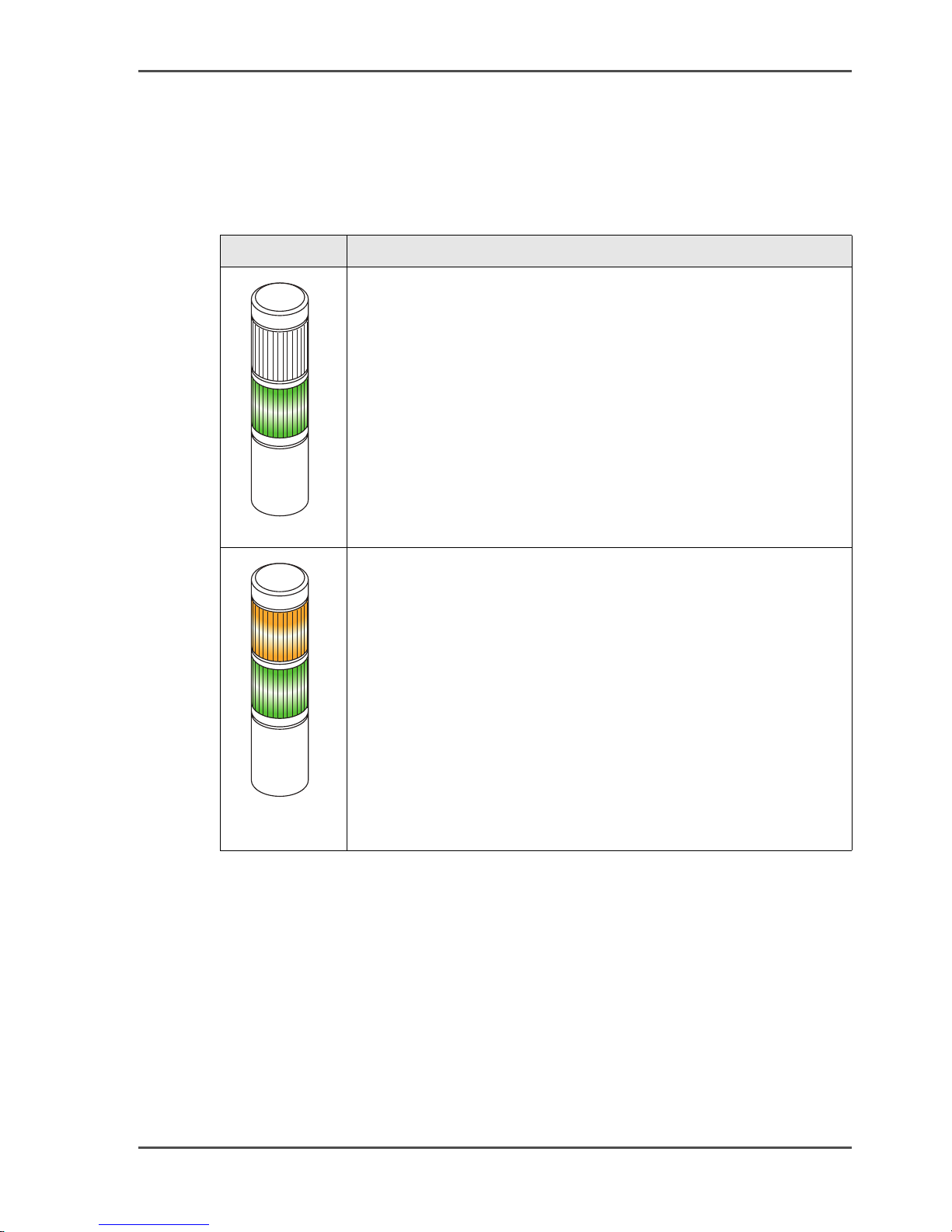
Displays
The most important displays are summarized in the following table:
[24]
Display Meaning
[48]
The printing system is in the 'Ready' status.
Service can set the printing system so that the Operator Attention
Light (OPAL) only lights up green in the 'Printing' status.
There is no warning.
(green)
[49]
(flashing
green/orange)
There is a warning in the 'Ready' status.
57

Operator Attention Light (OPAL) (optional)
Display Meaning
[50]
The printing system is in the 'Stop' st atus.
(orange)
[51]
An error occurred in the 'Ready' status
or the printing system has stopped because there is a warning.
(flashing orange)
58 Chapter 3 Description of the printing system

Operating elements in the printing system
Operating elements in the printing system
Example
All operating elements for normal, incident-free printing operation are designed in
blue-green, e.g.:
[52]
59

Paper specifications
Paper specifications
General information
The paper should comply with the paper specification for continuous printing
systems (see Other documents on page 26) and must be stored according to climatic
regulations in order to achieve higher availability of the printing system.
Non-compliance with the paper specifications can cause damage to the printing
system and may also result in the release of substances from the paper that can
contaminate the environment or have a detrimental effect on health. Océ Printing
Systems GmbH accepts no liability for such damages.
The printing system is designed to process a wide range of paper types. Ho wever , the
operational properties of the printing system and the print quality also depend on
factors such as:
■ Paper quality
■ Grammage
■ Moisture content
■ Dimensional stability
■ Smoothness, etc.
Before using new media, ensure that they comply with the paper specifications. If in
doubt, please contact the paper laboratory at:
Océ Printing Systems GmbH
SWS SI 4
Postfach 1260
85581 Poing
Germany
Paper types
All media that comply with the requirements of the electrophotographic printing
method can be used in all specified formats and paper weights.
Using other paper qualities may result in reduced operational results, lower
availability and possibly also higher usage of consumables and expendables.
Paper handling
The climate (temperature and relative humidity) of the storeroom and processing
room is of major importance in ensuring optimum paper processing. Unsuitable
conditions can, for example, giv e the paper an excessive curl, make it bumpy , or alter
its electrical resistance.
60 Chapter 3 Description of the printing system

Paper specifications
Observe the following guidelines to ensure that the original high quality of the paper
is not impaired in any way.
■ Store the paper in its packaging until it is used.
■ Do not store paper on the floor or next to walls, or in the vicinity of water pipes,
radiators, ventilators, windows (sunlight) etc.
■ Do not store paper in rooms in which the ambient conditions are subject to
constant change.
■ Before you use the paper, store it (in its packaging) near the printing system for
a few days if possible, or at least for 24 hours, to equalize temperature between
paper and room temperature.
■ Do not unpack more paper than you need.
■ Always use opened boxes of paper first. If you have to store open packs over a
longer period of time, cover the paper with protective film, so that no
climate-related changes occur.
61

Paper feed options
Paper feed options
Introduction
A floor-level paper feed to the paper web from the right or left is available for the
Océ VarioStream 8000 as an optional extra in addition to the standard paper feed.
Paper track with standard paper feed
[53]
62 Chapter 3 Description of the printing system

Paper track with floor-level feed (optional)
[54]
Paper feed options
[54] Floor-level feed from the right
[55]
[55] Floor-level feed from the left
63

Paper feed options
64 Chapter 3 Description of the printing system

Chapter 4
Operator panel description
65

Description of the Operator Panel — Overview
Description of the Operator Panel — Overview
Operator panel description
This section describes the individual areas of the operator panel with the most
important menus, buttons and icons.
The areas of the operator panel
The operator panel is divided into the following areas:
[56]
1
2 3
Description
[25]
Area Description
1 Toolbar - overview on page 67
2 'VarioStream' menus — overview on page 81
3 Menu display on page 88
66 Chapter 4 Operator panel description

Toolbar
Toolbar - overview
Overview
The toolbar can be used to access important functions in the printing system quickly
and to switch directly to frequently used menus.
[57]
123
Toolbar - overview
[26]
Area Description
1 Buttons and displays in the left-hand area on page 68
2 Buttons and displays in the center area on page 70
3 The buttons in the frame toolbar can be used to quickly access su-
perordinate functions for the complete printi ng system and to
switch directly to frequently used menus.
For more information on the buttons in this frame toolbar, see
Help on the 'General' menus
67

Buttons and displays in the left-hand area
Buttons and displays in the left-hand area
Function of the buttons
[27]
Button Function
[58]
[59]
[60]
Switches the printing system to ready for operation from the
'Stop' or error states.
Prerequisites:
■ No errors present
■ Controller and system control are ready
Switches the printing system to the 'Stop' status or cancels a current function.
N on P rocess R un O ut expels the last printed pages from the
printing system. The pages already printed are fused.
Prerequisite:
■ This function can only be executed in 'Stop' status.
Display for Océ VarioStream 8000 single
[28]
Display Function
[61]
Indicates that print data has been transferred from the host to a
printing system.
[62]
Standard display (no current print data from the host).
Display for Océ VarioStream 8000 twin
[29]
Display Function
[63]
Indicates that the print data has been transferred from the host to
both printers.
[64]
Indicates that print data has only been transferred from the host to
printer 1.
[65]
Indicates that print data has only been transferred from the host to
printer 2.
[66]
Standard display (no current print data from the host).
[67]
Indicates that the controller is performing a restart.
If this display appears, the print data transmission from the host
must be repeated, as proper printing or fusing of the last pages i s
no longer guaranteed against errors.
68 Chapter 4 Operator panel description

Display Function
[68]
Standard display (no controller restart).
[69]
Indicates that printers 1 and 2 are operating synchronously for a
twin printing system.
Buttons and displays in the left-hand area
69

Buttons and displays in the center area
Buttons and displays in the center area
Introduction
You can use the buttons in the cent er area of the toolbar to switch to frequently used
menus.
Buttons
[30]
Button Function
'Job control' Switches to the buttons under 'Job control' in the 'Emula-
tions' menu.
'Channel control' Switches to the 'Channels' menu.
The following buttons are available here:
[70]
Activates the channel. The connecting icon is closed.
[71]
deactivates the channel. The connecting icon is opened.
During the time required to activate or deactiv ate a channel, the connecting icon is displayed in yellow.
[72]
If a message was also transmitted by the data stream, this
icon is displayed.
Click here to switch directly to the 'Job preparation' tab
in the 'Job setup' menu. The complete message will be
displayed there.
[73]
If there is a new message from another user, this icon is
displayed.
Click here to switch directly to the 'Notes' menu. This is
where all notes or messages are displayed.
[74]
Flashes when there is an error message.
[75]
Flashes when there is a warning.
[76]
Flashes when there is information.
When there is no error message, warning or information,
this button is hidden.
Clicking this b utton switches to the 'Errors and warnings'
menu.
70 Chapter 4 Operator panel description

Button Function
[77]
Indicates that remote access is activated. The Service
center can use this to perform remote diagnostics during
print operation.
Clicking the button deactivates remote access directly
without having to go through the menu.
[78]
Also indicates that remote access is acti vated.
[79]
Indicates that remote access is not activated.
Clicking the button acti vates remot e access directly without having to go through the menu.
[80]
Switches to the 'Consumable counter' menu.
In this menu the current counter values and their respective limit values are displayed for all consumables and
expendables of the printing system.
Buttons and displays in the center area
'Service ticket' Switches to the 'Service ticket' menu.
Status displays
The current printer status is displayed on the centre of the toolbar. The individual
status displays have different background colors:
■ Green: The printing system is printing or is ready to print. If the printing of data
integrity marks is turned off for the current conf iguration, an additi onal message
to this effect will appear.
■ Red: The printing system is stopped, operator intervention is necessary.
■ Gray: all other printer states
This menu displays all the data required to notify the relevant Service center.
71

Buttons and displays in the center area
Status displays with green background
[31]
Display Meaning
'Ready' The printing system is ready to print, there are no error
messages.
'Printing' Normal print operation.
'Preparation' The printing system switches from the 'Stop' status to the
'Ready' status.
'Pre-/post-processing
not ready'
The printing system is ready to print, but the
pre/post-processing unit is not.
Status displays with red background
[32]
Display Meaning
'Operator intervention
necessary'
An error message is displayed. The error must be correct-
ed, otherwise printing cannot continue.
All current messages are also displayed in the 'Errors and
warnings' menu.
Status displays with gray background
[33]
Display Meaning
'Initialization' The printing system is being initialized and is not yet
ready for printing.
'Insert paper' The paper web can be inserted.
'Powering off' The printing system is being prepared to power off. A
shut-down setup is be ing wri tten, all components are be-
ing exited.
'Setup' A setup is being loaded or saved.
'Special functions' Consumables are being replaced or the printing system is
being cleaned.
'Stop' The printing system has stopped.
'Preparation' The printing system is switched on, device control is be-
ing prepared.
'Pre-/post-processing
not ready'
Printing is interrupted because the paper
pre/post-processing unit has stopped. The printing proc-
ess will continue when the paper pre/post-processing unit
is ready.
72 Chapter 4 Operator panel description

Display of error messages
As soon as an error occurs on the printing system, it is displayed within the status
display with black text on a white background. The same applies for warnings.
Buttons and displays in the center area
73

Frame toolbar
Frame toolbar
Buttons
The buttons in the frame toolbar can be used to quickly access superordinate
functions for the complete printing stream and to switch directly to frequently used
menus.
[34]
Button Function
[81]
[82]
[83]
[84]
[85]
[86]
[87]
[88]
Switches to the 'User profile' menu.
The language of the operator panel can be changed in this menu.
Indicates that the presently logged-on user possesses the access
ticket.
Clicking releases the access ticket dire ctly without going through
the menu.
Indicates that the access ticket is released for other users.
Clicking requests the access ticket directly without going through
the menu.
Opens the Help window.
Switches to the 'Change user' menu.
Users can be registered or canceled in this menu.
Displays the user currently logged on.
Powers down the entire printing system if the 'Do you really want
to power off the printing system?' query is confirmed.
Changes from each sub-menu directly to the main menu of the
printing system or the Paper Path Manager.
74 Chapter 4 Operator panel description

Menu tree
Menu tree — overview
Note:
The menus displayed in the menu tree depend on the different rights for the
individual user categories.
This documentation describes all menu options normally set up for the user
categories "Operator" and "Key operator".
Information on the P aper Path Manager can be found in Help in the printing system
operator panel. Information on the Web Buffer can be found in Help in the printing
system operator panel and in the Océ Web Buffer user guide.
Main groups
All menus can be accessed via the menu tree. The menus are structured into main
groups, for example:
Menu tree — overview
■ [00] 'General'
■ [02] 'VarioStream'
■ [BU] 'Web Buffer'
■ [FF] 'Paperpath Manager'
■ [xx] Any additional device for paper pre-print processing and/or post-print
The numbers before the main groups (= 'Paper sequence ID') are required to identify
the devices in the print processing unit.
Navigation
In these menus, you can define user settings valid for the entire print processing
unit.
In these menus, you can set the relevant parameters for the VarioStream 9000
printing system.
In these menus, you can set the relevant parameters for the paper web buffer
required to operate the multi-color printing systems.
In these menus, you can gain an overvie w of all UP3I-capable devices of the print
processing unit.
processing.
Clicking the switches in the menu tree let s you show or hide other menu leve ls, e. g.:
75

Menu tree — overview
[89]
Y ou can switch direct ly to the main menu from any menu. Click the following button
in the toolbar for this purpose:
[90]
Overview
Here you will find information on the following topics:
■ 'General' menus — overview on page 77
■ 'VarioStream' menus — overview on page 81
76 Chapter 4 Operator panel description

'General' menus
'General' menus — overview
Overview
You can define the user settings valid for the entire printing system in the 'General'
menus.
Note:
Menus that can only be opened by t he "Key Operator" user by default are shown in
bold in the table.
[35]
Menu Description
'General' menus — overview
'User management'
The sub-menus contain the user settings relating to the Key
Operator.
'User' The sub-menus contain the user settings relating to the Oper-
ator.
'Security' The sub-menus contain security-related settings and displays.
77

'User management' menus
'User management' menus
Overview
Note:
The menus listed in the table can only be accessed by the"Key Operator" user.
The menus under 'User management' contain the user settings relating to the Key
Operator.
[36]
Menu Description
'Add user' Add new users or user templates
'Delete user' Delete users or user templates
'Edit user' Settings for:
■ Password
■ User rights for menus and elements
■ Language
78 Chapter 4 Operator panel description

'User' menus
Overview
The menus under 'User' contain the user settings relating to the Operator.
[37]
Menu Description
'Change user' Log a user on or off
'User profile' Select the operator panel language and change the password
'Tools' Two different functions are combined into this menu:
'User' menus
■ Facilitate screen cleaning during printing
■ Also write an error log when the 'Operator trace' me nu can
no longer be started.
'Emergency display for error'
Display of current error and warning messages and information in the event that the printing system-spec ific menus and
consequently the 'Errors and warnings' menu cannot be
opened.
79

'Security' menus
'Security' menus
Overview
The menus under 'Security' contain security-related settings and displays.
[38]
Menu Description
'Access ticket' Requesting or releasing the access ticket for a specific op-
erator panel in the printing system.
'Network management LAN A/LAN B'
Overview of the computer connected to the printing system.
'Safety violations' Display of any security violations.
80 Chapter 4 Operator panel description

VarioStream menus
'VarioStream' menus — overview
Display of basic information
The following basic information on the printing system is displayed in the
'VarioStream' menu:
[39]
Display Description
'VarioStream' menus — overview
'User counter
(total)'
'Print job:' Current print job
'Job setup:' Currently loaded job setup
'Color setup:' Currently loaded color setup
'Printing system:'
'Serial No.:' Serial number of the printing system
'Emulation:' Currently selected mode
'VarioStream' menus
Number of all 12" pages previously printed in user operation
Further counters are displayed in the 'General counters' menu.
The job name will be displayed at the same time as data transfer
to the printing system. As up to 256 pages can be saved in the
page buffer, the job name will no longer be displayed for a short
time before printing the last pages.
In addition to the name, the Color Setup Verification ID (CSVID)
is also displayed.
Description of the printing system
The sub-menus contain all settings and displays relating to the Océ VarioStream
8000 printing system.
'Displays' menus
The sub-menus contain displays on current error and warning messages and the
various counters on the printing system.
'Configuration' menus
The sub-menus contain the parameters relevant for setting the printing system.
81

'VarioStream' menus — overview
'Setup' menus
In setups, special settings for frequently recurring print requests can be grouped
together and saved. By loading a setup, the printing system can be configured
quickly with the right parameters for a print request.
If the printing system is powered up and it is not possible to load a setup, then the
settings from before the printing system was po wered down continue to apply.
'Changing consumables' menus
The sub-menus contain the procedures for replacing consumables and expendab les
and for cleaning the printing system. A menu for identifying the toner used is al so
available.
82 Chapter 4 Operator panel description

'Displays' menus
Introduction
The sub-menus contain displays on curre nt error and warning messag es and v arious
counters on the printing system
'Errors and warnings' menu
Displays the current error and warning messages and information.
'General counters' menu
Displays page counters, warm-up time, user counters and toner types.
'Consumable counter' menu
'Displays' menus
Displays the current counter values and the rele vant limit values for all c onsumables
and expendables for the printing system.
'Consumable history' menu
Displays replacement procedures for all replaced consumables and expendables,
each with time and counter reading.
'Notes' menu
Display and input of notes or messages. The entries are stored for 3 months.
83

'Configuration' menus
'Configuration' menus
Introduction
The menu shows the current configuration of the printing system.
The printing system can be configured with the help of the parameters in the
sub-menus.
'Paper' menu
The sub-menus contain the parameters for the paper webs to be printed.
'Printing system' menu
Using the sub-menus, it is possible to set the operating mode, configure the paper
path, convert the printing system and set the inline turn bar fan.
'Print parameters' menu
The sub-menus contain specific parameters for the printing system.
'Color' menu
The sub-menus contain all parameters relevant for printing with color (or black).
'Emulations' menu
Displays the emulations, and buttons for job control, restarting, and the PCL settings.
'Channels' menu
Display and setting of parameters for coupling the printing system to the network.
'Special functions' menu
The sub-menus contain the settings and displays for superordinate parameters and
procedures for configuring and converting the printing system.
84 Chapter 4 Operator panel description

'Setup' menus
'Setup' menus
In setups, special settings for frequently recurring print requests can be grouped
together and saved. By loading a setup, the printing system can be configured
quickly with the right parameters for a print request.
If the printing system is powered up and it is not possible to load a setup, then the
settings from before the printing system was powered down continue to apply.
'Overview of loaded setups'
Displays all currently loaded setups. If the current settings have been changed since
the time when the setup was loaded, this is also displayed.
On the 'Color setup', the Color Setup Verification ID ('CSVID') is displayed in
addition to the name. Whether or not the 'CSVID' is displayed decimally or
hexadecimally depends on the setting in the 'Emulations' - 'General' menu under
'Display of CSVID'.
'Setup' menus
If the relevant channel is available, information on the channel setup is also
displayed.
'Job setup' menu
Display and editing of generally valid print job parameters.
'Color setup' menu
Display of parameters for the colors currently used in the printing system (including
black).
In color setups, parameters for the colors currently used in the printing system can
also be loaded and saved. The color setups are independent of the job setups.
Menu 'Setup channel A' / 'Setup channel B' / 'Setup channel C'
Display of setups for 'Channel A', 'Channel B' or 'Channel C'.
Channel-specific settings for frequently rec urring print jobs can be combined into a
channel setup and saved under a name. By loading a setup of this type, the printing
system is automatically set up with the corresponding parameters for the print job.
85

'Replace consumables' menus
'Replace consumables' menus
'Replace consumables' menus
The sub-menus contain the procedures for replacing consumables and expendab les
and for cleaning the printing system. A menu for identifying the toner used is al so
available.
'Replace active filter' menu
Procedure for replacing the active filter.
'Replace pressure roller'
Procedure for replacing the pressure roller.
'Replace corotrons'
Procedure for replacing the charge and discharge corotrons.
'Change developer'
Procedure for draining or filling the developer in the developer station
'Fill developer'
Procedure for filling the developer in the developer station
'Replace heater'
Procedure for replacing the heating element.
'Replace the fine filter'
Procedure for replacing the fine filter.
'Replace fusing oil bottle'
Procedure for replacing the fuser oil bottle.
'Replace fuser roller'
Procedure for replacing the fuser roller.
86 Chapter 4 Operator panel description

'Replace photoconductor drum'
Procedure for replacing the photoconductor drum.
'Rotate photoconductor drum'
Procedure for inserting the photoconductor drum.
'Replace cleaning brush'
Procedure for replacing the cleaning brush.
'Replace cleaning belt'
Procedure for replacing the cleaning belt.
'Replace toner bottle'
'Replace consumables' menus
Procedure for replacing the toner bottle
'Fill toner box'
Procedure for filling the developer in the toner box.
'Replace waste toner bottle'
Procedure for replacing the waste toner bottle
'Toner bottle identification'
Displays information on the toner used for the main color.
'Replace/clean transfer roller'
Procedure for replacing or cleaning the transfer roller.
87

Menu display
Menu display
Introduction
This area shows the menu selected in the menu tree.
Direct help via the F1 key
Detailed information on all menus and operating controls is av ailable direc tly in the
operator panel via the context-sensitive direct help. The context-sensitive help
system can be called up by selecting the relev ant menu or operating element and then
pressing the F1 key.
If necessary , all the requirements for setting the respective parameters are also listed
in the context-sensitive direct help. Specified standard settings and values are
denoted in bold.
88 Chapter 4 Operator panel description

Chapter 5
Working with the operator
panel
89

Working with the operator panel — overview
Working with the operator panel — overview
Working with the operator panel
This section explains how you manage all user settings, how you select or enter
parameters on the operator panel, how you collect special settings for frequently
recurring print jobs using setups, how you manage resources for printing operation
and how you replace consumabl es and expendables using the operator panel.
Overview
Here you will find information on the following topics:
■ Manage user settings (Key Operator) — overview on page 91
■ Manage user settings (Operator) — overview on page 99
■ Selecting settings and entering values on page 104
■ Applying or resetting settings on page 105
■ Configuring operation mode on page 106
■ Working with setups — overview on page 107
■ Managing resources — overview on page 114
■ Editing 'Replace consumables' menus on the operator panel on page 117
90 Chapter 5 Working with the operator panel

Manage user settings (Key Operator) — overview
Managing user settings (Key Operator)
Manage user settings (Key Operator) — overview
Introduction
By default, 3 user groups are pre-def ined: Operator, Key Operator and Service. Any
changes made to their associated user profiles will be reset when a new operator
panel version is installed.
However, changes to profiles of self-created users will be unaffected by the
installation of a new operator panel version.
Pre-defined user for VarioStream 9000
Four users are pre-defined within the Operator user group in the VarioStream 9000
printing system:
■ Sample operator 1-1
(for single color bilevel printing)
■ Sample operator 1-1 ML
(for single color multilevel printing)
■ Sample operator color
(for multicolor bilevel printing)
■ Sample operator color ML
(for multicolor multilevel printing)
The following table indicates which color menus are displayed for each user:
91

Manage user settings (Key Operator) — overview
[40]
Menu Sample op-
erator
1-1
'Contrast' yes yes yes yes
'Default values' yes yes yes yes
'Raster' no yes no yes
'Tone transfer curve' no yes no yes
'Color properties' no no yes yes
'Color station selection' no no yes yes
'Color order' no no yes yes
'PCL simple color' no no yes yes
Overview
Sample operator
1-1 ML
Sample operator
color
Sample operator
color ML
As Key Operator, you can normally make the following user settings:
■ 'Add user' on page 94
■ 'Delete user' on page 95
■ Setting password/'General' tab on page 96
■ Releasing and blocking menus and elements/'User rights' tab on page 97
■ Setting language/'User profile' tab on page 98
Note:
Once a user is logged on he can in principle o nly add, delete or ed it other users of a
lower user group. Users with the same or higher user level are not listed in the
selection lists.
92 Chapter 5 Working with the operator panel

Advanced password protection (optional extra for the Variostream 9000)
Advanced password protection (optional extra for the
Variostream 9000)
Introduction
The "Extended password protection" function can be activated by Service as an
option.
Rules
In this case, all users must use a password according to the following rules:
■ It contains at least 8 characters.
■ It contains at least 1 special character or 1 figure.
■ A maximum of 2 identical characters may follow each other.
■ It is case sensitive.
■ The last 3 passwords may not be the same.
■ The new password is valid for 3 months.
Note:
The password can contain any number of characters if the "Extended password
prote ction" func tion was not ac tivated by Service . The passwo r d w ill in this case be
valid indefinitely.
93

'Add user'
'Add user'
To add a user
[41]
Proceed as follows:
1. Click on the 'General' -> 'User management' -> 'Add user' menu.
2. Select user template.
3. Enter a name for the new user. The following characters are permitted here:
The settings for this user template will be adopted for the new user. These
settings can then be adjusted in the 'User management' -> 'Edit user' menu if
necessary.
■ A-Z
■ a-z
■ 0-9
■ Underline, hyphen, blank space
4. Click on the 'Create' button.
5. Enter a new password, confirm password and then click on 'OK'.
The password can contain any number of characters if the "Extended password protection" function was not activated by Service.
Extended rules will apply to the password if Service has activated the "Extended password protection" function. see Advanced password protection
(optional extra for the Variostream 9000) on page 93.
94 Chapter 5 Working with the operator panel

'Delete user'
Introduction
All user-defined users and possible pre-defined users "Sample operator" can be
deleted, with the exception of the pre-defined user groups Operator and Key
Operator.
To delete a user
[42]
Proceed as follows:
1. Click on the 'General' -> 'User management' -> 'Delete user' menu.
2. Select the names of the user.
3. Click on the 'Delete' button and confirm.
'Delete user'
95

Setting password/'General' tab
Setting password/'General' tab
Note:
A password will remain valid indefinitely if the "Extended password protection"
function has not been activated by Service.
A password will remain valid for 3 months if the "Extended password protection"
function has been activated by Service. When the password has expired, you can
enter a new password in the 'Edit user' menu or the 'User profile' menu.
To set a password
[43]
Proceed as follows:
1. Click on the 'General' -> 'User management' -> 'Edit user' menu.
2. Select the User.
3. Click on the 'General' tab.
4. Click the 'Change password' button.
5. Enter a new password, enter it again in 'Password confirmation' and then
click on 'OK'.
The password can contain any number of characters if the "Extended password protection" function was not activated by Service.
Extended rules will apply to the password if Service has activated the "Extended password protection" function. See Advanced password protection
(optional extra for the Variostream 9000) on page 93.
6. Click the 'Apply' button.
96 Chapter 5 Working with the operator panel

Releasing and blocking menus and elements/'User rights' tab
Releasing and blocking menus and elements/'User rights'
tab
Note:
You can activate or block menus and elements for self-created users. Menus and
elements cannot be activated or blocked for the predefined user groups.
For security reasons, the 'Change user', 'User profile' and 'Network management
LAN A/LAN B' menus cannot be hidden.
To release or block menus and elements
[44]
Proceed as follows:
1. Click on the 'General' -> 'User management' -> 'Edit user' menu.
2. Select the User.
3. Click on the 'User rights' tab.
All menus and elements in the operator panel will be displayed. The icons in
the check boxes mean for the user group or the users currently selected:
This menu or element is activated. It cannot be blocked.
This menu or element is blocked. It cannot be activated.
This menu or element is blocked for predefined user groups. It can be ac-
tivated for self-created users by clicking on it.
This menu or element is currently activ ated. It can be blocked b y clicking
on it.
This menu or element is currently blocked. It can be acti vated by clicking
on it.
4. Under 'Menus', acti vate the checkboxes in front of the menus that are to be
displayed for the user in the menu tree.
If a menu is not supposed to be displayed, deactivate the respective check box. This also prevents the user from accessing all subordinate menus.
In principle, only those menus or elements can be activated that are also activated for the editing user himself.
5. Under 'Element s', cli c k on th e checkboxes in front of the operator elements
for a specific menu that are to be editable for this user.
If an element should be read-only (not editable), deactivate the respective
checkbox.
6. Click on the 'Apply' button.
97

Setting language/'User profile' tab
Setting language/'User profile' tab
Introduction
The operator panel language can be selected in the 'User profile' tab . The appearance
of the operator panel cannot be changed for the user groups "Operator" and "Key
Operator."
To set a language
[45]
Proceed as follows:
1. Click on the 'General' -> 'User management' -> 'Edit user' menu.
2. Select the User.
3. Click on the 'User profile' tab.
4. Select the desired language from the 'Language' list.
5. Click the 'Apply' button.
98 Chapter 5 Working with the operator panel

Manage user settings (Operator) — overview
Managing user settings (Operator)
Manage user settings (Operator) — overview
Overview
As an Operator, you can normally make the following user settings:
■ Log on as user and request an access ticket on page 100
■ Changing password/'Password' tab on page 101
■ Changing language/'User profile' tab on page 102
■ Log off as user on page 103
99
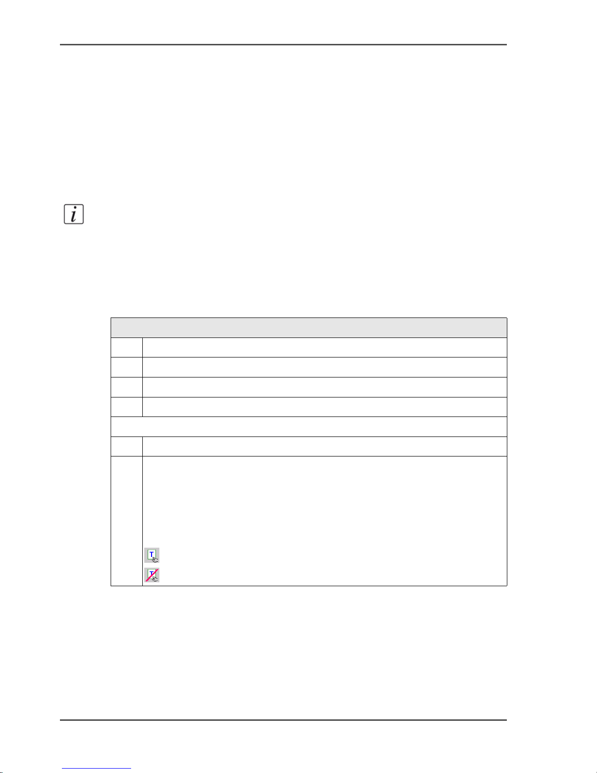
Log on as user and request an access ticket
Log on as user and request an access ticket
Introduction
T o be able to set parameters on the operator panel, you must first log on as a user and
then request the access ticket.
The access ticket ensures that parameters are not set by different users at parallel
operator panels.
Note:
A message will be displayed if a user on a higher authorization level has already
requested the access ticket. The access ticket can be requested directly from users
with the same authorization level.
To log in as a user and request the access ticket
[46]
Proceed as follows:
1. Click on the 'General' -> 'User' -> 'Change user' menu.
2. Select the desired user from the selection list.
3. Enter password.
4. Click on the 'Log on' button.
Only if several operator panels are connected to the printing system:
5. Click on the 'General' -> 'Security' -> 'Access ticket' menu.
6. Click on the 'Request access ticket' button.
If the access ticket has already been requested, the button is deactivated.
Note
The access ticket can also be requested and relea sed directly via the buttons
in the frame toolbar without going through the menu:
[91]
[92]
100 Chapter 5 Working with the operator panel
 Loading...