


Océ
Océ | Operating Manual
Océ VarioStream 7000 SINGLE
Pinfed

...and how about training?
We also offer courses in our Training Center for the product described.
Information:
Phone +49 8121 72 3940
Fax +49 8121 72 3950
Océ Printing Systems GmbH
ITC
Postfach 1260
85581 Poing
Germany
Edition 2005/11
Order no. A29246-X20-X-4-7680
Copyright © Océ Printing Systems GmbH 2004, 2005
The product names Océ VarioStream
®
, Océ Web Buffer 9000®, Océ VarioPrint® and Océ CustomTone
®
are subject to trademark.
All rights reserved, including rights of translation, reprinting, reproduction by copying or any other method. Offenders
will be liable for damages.
All rights, including rights created by patent grant or registration of a utility model or design, are reserved.
Delivery subject to availability; right of technical modifications reserved.

1
Notes on the printing system documentation
5
Operating the printing system
2
Safety
3
Description of the printing system
4
Operator panel
6
Cleaning the printing system
8
Correcting faults
7
Replacing consumables and expendables
Index
Appendix


Table of contents
A29246-X20-X-4-7680 / fa_20_baIVZ.fm
Table of contents
1 Notes on the printing system documentation ................................................... 11
1.1 Overview.................................................................................................................. 11
1.2 Signposts ................................................................................................................ 12
1.3 Using "Help" ............................................................................................................ 13
1.3.1 Contents .................................................................................................... 14
1.3.2 Index ......................................................................................................... 15
1.3.3 Search ...................................................................................................... 16
1.3.4 Direct help ................................................................................................ 17
1.4 Symbols in the text ................................................................................................. 19
1.5 Symbols in diagrams and illustrations .................................................................... 20
1.6 Other documents .................................................................................................... 22
1.7 Manufacturer of the printing system ....................................................................... 22
1.8 Statutory requirements ........................................................................................... 23
2 Safety...................................................................................................................... 25
2.1 Overview.................................................................................................................. 25
2.2 Intended Purpose ................................................................................................... 26
2.3 Operating and service clearance areas .................................................................. 27
2.4 Flagging of safety directives ................................................................................... 28
2.5 Warning and Information signs ............................................................................... 29
2.6 Accident and damage prevention ............................................................................ 31
2.6.1 Personal Representations ......................................................................... 31
2.6.2 Operation ................................................................................................. 32
2.6.2.1 Operator..................................................................................... 32
2.6.2.2 Safety covers ............................................................................ 33
2.6.2.3 Cleaning .................................................................................... 33
2.6.2.4 Foreign bodies, noises .............................................................. 33
2.6.2.5 Cooling, heat, emissions ........................................................... 34
2.6.2.6 Consumables and expendables................................................. 34
2.6.2.7 Optical wave guide .................................................................... 34
2.6.2.8 Laser .......................................................................................... 35
2.6.2.9 Remote control via LAN ............................................................. 35
2.6.3 Assembly and installation ......................................................................... 35

Table of contents
fa_20_baIVZ.fm / A29246-X20-X-4-7680
2.6.4 Transport .................................................................................................. 36
2.6.5 Repairs ..................................................................................................... 36
2.6.6 Fire ........................................................................................................... 36
2.6.7 Disposal .................................................................................................... 36
2.7 Safety regulations and standards ........................................................................... 37
2.7.1 CE Mark ................................................................................................... 38
2.7.2 Accident prevention regulations for the replacement cart for developer
stations (optional) ...................................................................................... 38
3 Description of the printing system ..................................................................... 41
3.1 Overview ................................................................................................................. 41
3.2 Device overview ..................................................................................................... 41
3.2.1 Doors and covers ..................................................................................... 42
3.2.2 Internal view ............................................................................................. 45
3.2.3 Toner bottle identification ......................................................................... 48
3.3 Operating elements ................................................................................................ 50
3.3.1 Operator panel on paper transporter ........................................................ 50
3.3.2 Stacker operator panel ............................................................................. 51
3.4 Paper specifications ............................................................................................... 55
3.4.1 General information ................................................................................... 55
3.4.2 Paper types .............................................................................................. 55
3.4.3 Paper handling ......................................................................................... 56
3.5 Paper feed options ................................................................................................. 57
4 Operator panel ....................................................................................................... 59
4.1 Overview.................................................................................................................. 59
4.2 Operator panel description ..................................................................................... 60
4.2.1 Toolbar ..................................................................................................... 61
4.2.1.1 Buttons and displays in the left-hand area ................................. 62
4.2.1.2 Center area buttons and displays ............................................. 64
4.2.1.3 Frame toolbar............................................................................. 69
4.2.2 Menu tree ................................................................................................. 71
4.2.2.1 Menus <General> ..................................................................... 73
4.2.2.2 Menus<VarioStream> ............................................................... 74
4.2.2.3 Menus <Paper Path Manager> ................................................. 78
4.2.3 Menu display ............................................................................................ 79
4.3 Using the operator panel ........................................................................................ 80
4.3.1 Managing user settings (key operator) ..................................................... 81
4.3.1.1 Adding users ............................................................................. 81

Table of contents
A29246-X20-X-4-7680 / fa_20_baIVZ.fm
4.3.1.2 Deleting users ........................................................................... 82
4.3.1.3 Editing users ............................................................................. 82
4.3.2 Managing user settings (operator) ........................................................... 84
4.3.2.1 Logging on as user and requesting the access ticket ............... 85
4.3.2.2 Changing password .................................................................. 86
4.3.2.3 Changing language ................................................................... 86
4.3.3 Setting parameters ................................................................................... 87
4.3.3.1 Selecting settings and entering values ..................................... 88
4.3.3.2 Apply or reset parameters.......................................................... 89
4.3.4 Starting and completing the replacement of consumables and
expendables 90
5 Operating the printing system ............................................................................ 95
5.1 Overview.................................................................................................................. 95
5.2 Powering on the printing system ............................................................................ 96
5.3 After print stop, switch the printing system back to "Ready" .................................. 99
5.4 Inserting paper (pinfed) ........................................................................................ 100
5.4.1 Semi-automatic paper insertion .............................................................. 106
5.4.2 Manual paper insertion after a paper jam ............................................... 112
5.5 Setting the external paper feed lever..................................................................... 120
5.6 Settings when changing paper (pinfed) ................................................................ 121
5.6.1 Settings on paper transporter ................................................................. 121
5.6.1.1 Setting the calibration gap ...................................................... 121
5.6.1.2 Setting loop puller force .......................................................... 121
5.6.2 Settings on the tension roller unit or on the stacker ............................... 122
5.6.2.1 Settings on the tension roller unit............................................. 122
5.6.2.2 Settings on the stacker ............................................................ 122
5.6.3 Input at the operator panel ...................................................................... 125
5.7 Removing the paper stack .................................................................................... 131
5.8 Working with setups .............................................................................................. 133
5.8.1 Creating a new setup or changing a setup ............................................. 134
5.8.2 Importing a setup ................................................................................... 136
5.8.3 Exporting a setup ................................................................................... 137
5.9 Printing with another color .................................................................................... 138
5.9.1 Replacing the toner feed ........................................................................ 138
5.9.1.1 Removing toner feed................................................................ 138
5.9.1.2 Installing toner feed.................................................................. 142
5.9.2 Replacing the developer station ............................................................. 145
5.9.2.1 Removing the developer station .............................................. 145
5.9.2.2 Installing the developer station ................................................ 154

Table of contents
fa_20_baIVZ.fm / A29246-X20-X-4-7680
5.10 Converting the printing system ............................................................................. 162
5.10.1 Selecting a configuration ........................................................................ 164
5.10.2 Converting the printing system ............................................................... 165
5.10.2.1 Start conversion ...................................................................... 165
5.10.2.2 Replacing the toner feed ......................................................... 166
5.10.2.3 Replacing the developer station .............................................. 168
5.10.2.4 Replacing the photoconductor drum ....................................... 169
5.10.2.5 Replacing the fuser roller ........................................................ 170
5.10.3 Completing the conversion ...................................................................... 171
5.11 Emptying condensation water when using the High Temperature Kit (optional) ..172
5.12 Powering off the printing system .......................................................................... 173
6 Cleaning the printing system ............................................................................. 175
6.1 Overview................................................................................................................ 175
6.2 Cleaning intervals ................................................................................................. 177
6.3 Cleaning the paper path ....................................................................................... 179
6.4 Cleaning plastic strips ........................................................................................... 188
6.5 Cleaning the fuser station ..................................................................................... 191
6.6 Cleaning the soft fuser roller ................................................................................. 199
6.7 Cleaning the developer station ............................................................................. 203
6.8 Cleaning sensors ................................................................................................... 207
6.8.1 Cleaning the toner mark sensor .............................................................. 207
6.9 Cleaning the paper motion sensor and mirror ...................................................... 209
6.9.1 Cleaning the paper edge sensor in the fuser station .............................. 211
6.10 Cleaning the toner suction system ....................................................................... 213
6.11 Cleaning the corotrons ........................................................................................ 218
6.12 Cleaning the LED print head ................................................................................ 219
6.13 Cleaning the filter .................................................................................................. 220
6.14 Cleaning the operator panel ................................................................................. 223
6.15 General cleaning .................................................................................................. 224
7 Replacing consumables and expendables ....................................................... 225
7.1 Overview................................................................................................................ 225
7.2 Replacing consumables ....................................................................................... 226
7.2.1 Replacing the toner bottle ..................................................................... 226
7.2.2 Filling the toner box ................................................................................ 232
7.2.3 Replacing the waste toner bottle ........................................................... 233
7.2.4 Replacing the developer ........................................................................ 238
7.2.5 Replacing the fuser oil bottle .................................................................. 252
7.3 Replacing expendables ........................................................................................ 256

Table of contents
A29246-X20-X-4-7680 / fa_20_baIVZ.fm
7.3.1 Replacing the photoconductor drum ..................................................... 257
7.3.2 Run in photoconductor drum .................................................................. 263
7.3.3 Replacing the cleaning brush ................................................................ 263
7.3.4 Replacing corotrons ............................................................................... 269
7.3.4.1 Preparing corotron replacement .............................................. 270
7.3.4.2 Replacing the transfer corotron (1 cartridge) (pinfed) ............. 271
7.3.4.3 Replacing the transfer corotron (torn wire) (pinfed) ................ 275
7.3.4.4 Replacing charge corotrons (5 cartridges) .............................. 278
7.3.4.5 Replacing charge corotrons (torn wire) ................................... 281
7.3.4.6 Replacing discharge corotrons (2 cartridges) ......................... 284
7.3.4.7 Replacing the discharge corotron (torn wire) .......................... 287
7.3.4.8 Complete corotron replacement............................................... 290
7.3.5 Replacing the active filter ....................................................................... 291
7.3.6 Replacing the cleaning belt ................................................................... 297
7.3.7 Replacing the heater ............................................................................. 302
7.3.8 Replacing the fuser roller ...................................................................... 312
7.3.9 Replacing the pressure roller ................................................................ 320
7.3.10 Replacing the waste collector ................................................................. 326
7.3.11 Replacing the fine filter ........................................................................... 330
8 Correcting faults.................................................................................................. 337
8.1 Overview................................................................................................................ 337
8.2 Processing messages on the operator panel ....................................................... 338
8.2.1 Locating a message ............................................................................... 338
8.2.2 Continuing printing after errors have been corrected ............................. 341
8.3 Clogged toner suction ........................................................................................... 343
8.4 Poor print quality ................................................................................................... 348
8.4.1 Poor printing ........................................................................................... 348
8.4.2 Poor printing, cause and correction ........................................................ 349
8.5 Poor fusing quality ................................................................................................ 351
8.6 Permitting or blocking remote access ................................................................... 352
Appendix ...................................................................................................................... 355
Overview......................................................................................................................... 355
Consumables ................................................................................................................. 356
Consumables for VarioStream 7200, VarioStream 7300, VarioStream 7400 ...... 356
Consumables for VarioStream 7450, VarioStream 7550, VarioStream 7650 ...... 357
Consumables for VarioStream 7450 CX, VarioStream 7550 CX,
VarioStream 7650 CX ............................................................................. 359
Expendables .................................................................................................................. 361

Table of contents
fa_20_baIVZ.fm / A29246-X20-X-4-7680
Expendables for VarioStream 7200, VarioStream 7300, VarioStream 7400........ 361
Expendables for VarioStream 7450, VarioStream 7550, VarioStream 7650........ 362
Expendables for VarioStream 7450 CX, VarioStream 7550 CX,
VarioStream 7650 CX ............................................................................. 364
Cleaning materials and equipment ................................................................................. 365
Technical data ................................................................................................................ 367
Print speed ........................................................................................................... 367
Paper ................................................................................................................ 368
Electrical values ................................................................................................... 370
Emissions ............................................................................................................ 371
Mechanical conditions ......................................................................................... 371
Environmental conditions .................................................................................... 372
Dimensions and weight ....................................................................................... 372
Index .............................................................................................................................. 375

1 Notes on the printing system documentation
A29246-X20-X-4-7680 / all101.fm 11
1 Notes on the printing system documentation
1.1 Overview
The purpose of this documentation is to ensure that all printing system-related work is carried out safely and correctly. It contains safety directives that must be strictly observed.
Each section is divided into small, easy-to-understand subject areas. The beginning of each
section contains an overview to help you quickly find the precise information you are looking
for.
This section contains information on the following topics:
1.2 Signposts >>> page 12
1.3 Using "Help" >>> page 13
1.4 Symbols in the text >>> page 19
1.5 Symbols in diagrams and illustrations >>> page 20
1.6 Other documents >>> page 22
1.7 Manufacturer of the printing system >>> page 22
1.8 Statutory requirements >>> page 23

1.2 Signposts
12 A29246-X20-X-4-7680 / all101.fm
1.2 Signposts
This section 2 Safety gives you all necessary information on how to safely and efficiently
operate the printing system.
Section 3 Description of the printing system explains the structure of the printing system.
The operational controls are also described.
The section 4 Operator panel describes the individual areas of the operator panel with the
most important icons and buttons. You will also learn how to navigate in the menus, set parameters and start and complete the replacement of consumables and expendables.
The section 5 Operating the printing system explains how to power the printing system on
and off and the procedure for inserting, removing and changing the paper web.
Section 6 Cleaning the printing system explains the intervals to be followed for cleaning the
different assemblies.
Section 7 Replacing consumables and expendables describes in detail all steps required
to replace consumables or expendables.
Section 8 Correcting faults will help you eliminate paper jams or distortions of the print image.
The context-sensitive direct help on the operator panel provides information on the cause
and correction of specific error or warning messages.
Appendix will provide you with detailed information on all consumables and expendables.
In addition, the required cleaning agents and equipment are described along with the most
important technical data.
Specific subjects can be found more quickly by looking at the detailed index at the end of
the operating manual.
Note
Along with the operating manual, Help is also available in the operator panel of the
printing system. This Help is updated with every new version of the operator panel.
1.3 Using "Help"
A29246-X20-X-4-7680 / all102.fm 13
1.3 Using "Help"
Help on the operator panel of the printing system is operated using the following buttons:
Button Function
opens Help.
hides or displays the navigation area with the following tabs:
• Contents(see section 1.3.1 Contents, page 14)
• Index(see section 1.3.2 Index, page 15)
• Search(see section 1.3.3 Search, page 16)
When the navigation area is hidden, there is more space available to view
the help topics.
switches between the last help topics (backwards or forwards).
switches from any help topic directly to the Help start page.
closes Help.
Note
You can also open context-sensitive direct help for each operational element by selecting the respective element and then pressing the F1 key (see section 1.3.4 Direct
help, page 17).

1.3.1 Contents
14 A29246-X20-X-4-7680 / all102.fm
1.3.1 Contents
The Help is divided into different main groups:
• General
• VarioPrint 5000 or
VarioStream 9000 or
VarioStream 7000
• Paper Path Manager
• Paper post processing devices, if available
In the "Contents" tab, you can show or hide individual Help levels and select the desired
Help topic, e. g.:

1.3.2 Index
A29246-X20-X-4-7680 / all102.fm 15
1.3.2 Index
The "Index" tab provides quick access to the required information.
You can also search directly for a specific word within index entries.
Example:
Proceed as follows:
1. Enter the text into the "Search" input field.
2. Press Enter key.

1.3.3 Search
16 A29246-X20-X-4-7680 / all102.fm
1.3.3 Search
Via the "Search" tab you can launch the full text search. The full text search is used to find
one or more specific words in the entire Help. Uppercase or lowercase is not relevant for
the search.
The search results are listed with the title of the corresponding help topic, and are sorted
by level of matches and the frequency in which the word appears in the help topic, e. g.:
The circle in the first column indicates the degree of matching. The more filled the circle is,
the better the result matches the text that was searched for.
The number in the second column of the search result indicates how often it occurs in the
Help topic.
Proceed as follows:
1. Enter the text into the "Search" input field.
2. Press Enter key.

1.3.4 Direct help
A29246-X20-X-4-7680 / all102.fm 17
1.3.4 Direct help
Context-sensitive Direct Help provides detailed information on all:
• Menus
• Operating elements in menus
• Error messages and warnings
If necessary, all the requirements for a setting are also listed in the context-sensitive help
system. Specified standard settings and values are denoted in bold.
Starting direct help
Proceed as follows:
1. Select menu
or
select operating element
or
select message.
1 of 2

1.3.4 Direct help
18 A29246-X20-X-4-7680 / all102.fm
2. Press the F1 key.
The Direct Help is opened, e. g.:
Proceed as follows:
2 of 2

1.4 Symbols in the text
A29246-X20-X-4-7680 / all102.fm 19
1.4 Symbols in the text
Different symbols help you to find your way around the text:
For safety directives, different symbols and alert words are used depending on the degree
of danger:
Symbol Meaning
Menu <Sample> The name of a button or menu on the operator panel is enclosed
in angle brackets.
SAMPLE button Mechanical buttons are denoted in uppercase letters.
This symbol indicates tips for operating the printing system.
Caution
Warns against dangers that could lead to injuries.
Important
Warns against situations that could lead to damage to the printing system or disruptions to operation.

1.5 Symbols in diagrams and illustrations
20 A29246-X20-X-4-7680 / all102.fm
1.5 Symbols in diagrams and illustrations
If not otherwise indicated, diagrams and illustrations of actions depict the starting position
of the respective component for the described step.
For easier understanding, the diagrams only depict the components that are directly relevant to the immediate context.
Arrows denote the positions where you have to perform an action or observe something in
particular. The color of the arrows denotes the type of actions and the sequence in which
they are performed:
Symbol Meaning
Black arrow: Direction arrow
Perform this action first
Grey arrow: Direction arrow
Perform this action next
If additional actions are depicted in a diagram, the numbers on the arrows indicate
the sequence in which they are to be carried out, e. g.:
2
3
2
3

1.5 Symbols in diagrams and illustrations
A29246-X20-X-4-7680 / all102.fm 21
White arrow: Note arrow
An action should be performed in this area,
e. g.:
Symbol Meaning

1.6 Other documents
22 A29246-X20-X-4-7680 / all103.fm
1.6 Other documents
If not otherwise indicated, the following documents are supplied with each printing system
in addition to the operating manual:
1.7 Manufacturer of the printing system
The printing system was manufactured by:
Océ Printing Systems GmbH
Postfach 1260
85581 Poing
Germany
Title Order number
Safety Information on Océ Printing Systems A29246-X23-X-1-79
Papierspezifikation Endlos-Drucksysteme
Paper Specification Continuous Feed Printing
Systems (English)
Deutsch: A29249-X2-X-10-59
English: A29249-X2-X-10-7659

1.8 Statutory requirements
A29246-X20-X-4-7680 / all103.fm 23
1.8 Statutory requirements
The information, data and instructions in this documentation were up-to-date at the time of
going to press. The right of technical modifications due to further development of the printing system is reserved. For this reason, the information, illustrations and descriptions in this
documentation cannot give rise to any claims for modifications or additions to printing systems that have already been shipped and accepted.
No liability is accepted for damages resulting from:
• Failure to comply with the documentation
• Errors due to improper handling
• Work performed incorrectly on the printing system
• Use of non-original parts and accessories
• Use of non-original consumables
• Unauthorized modification and retrofitting of the printing system by the agent or the
agent’s personnel.

1.8 Statutory requirements
24 A29246-X20-X-4-7680 / all103.fm

2 Safety
A29246-X20-X-4-7680 / all201.fm 25
2 Safety
2.1 Overview
This section gives you all necessary information on how to safely and efficiently operate the
printing system.
You will find information on the following topics:
2.2 Intended Purpose >>> page 26
2.3 Operating and service clearance areas >>> page 27
2.4 Flagging of safety directives >>> page 28
2.5 Warning and Information signs >>> page 29
2.6 Accident and damage prevention >>> page 31
2.7 Safety regulations and standards >>> page 37
Caution
Please also observe the safety directives in the documentation for any pre-processing
and post-processing devices that may be connected.

2.2 Intended Purpose
26 A29246-X20-X-4-7680 / all201.fm
2.2 Intended Purpose
The printing system shall only be considered as being used for its intended purpose if the
notices and instructions in this documentation are strictly observed.
The printing system is intended solely for printing materials that comply with the paper
specifications (see section 1.6 Other documents, page 22). The printing system may only
be used with the recommended consumables (see section Consumables, page 356) and
under the prescribed operating conditions (see section Technical data, page 367).
Any use of the printing system that does not comply with the above requirements can cause
damage to the printing system or property and moreover injury to persons.

2.3 Operating and service clearance areas
A29246-X20-X-4-7680 / fa202_single.fm 27
2.3 Operating and service clearance areas
The operating and service clearance areas for the printing system depicted in the following
diagram should not be obstructed in any way.
Dotted lines: additional area required for replacing the developer station
Dimensions in millimeters (inches)

2.4 Flagging of safety directives
28 A29246-X20-X-4-7680 / all203.fm
2.4 Flagging of safety directives
In addition to the safety directives in section 2.6 Accident and damage prevention, you must
also observe the safety directives outlined elsewhere in this documentation .
The following notational conventions are used for the safety directives in the text of the
manual:
Different icons and alert words are used depending on the degree of danger:
Example of a safety directive
Alert word
Type and/or source of danger, and consequences if the safety guideline is not
observed
Instructions on avoiding danger
Caution
Warns against dangers that could lead to injuries.
Important
Warns against situations that could lead to damage to the printing system or disruptions to operation.
Important
Fluid can seep inside the machine. This could cause irreparable damage to the electrical and mechanical components.
Do not place cleaning fluids on top of or in the immediate vicinity of the printing system.
Take care to prevent fluids from seeping into the printing system.
Icon

2.5 Warning and Information signs
A29246-X20-X-4-7680 / all203.fm 29
2.5 Warning and Information signs
The following signs are affixed inside the printing system at potential danger points:
Sign Meaning
Warning: Live electric parts
There are live electric parts behind protective covers bearing this sign.
These protective covers may only be removed by authorized Océ service personnel.
Warning: Rotating parts
Parts of the body (particularly fingers), unprotected long hair or loosely
hanging items of clothing and jewelry (e. g. ties, necklaces, belt ends...)
can be crushed, trapped or pulled into the printing system by the rotating mechanism in these areas.
Warning: Hot components
In order to prevent burns, you must observe the cooling periods and
other directives specified in the documentation for all work in these areas.
Observe documentation
For all work in this area, you must observe the relevant instructions in
the documentation.
The PC drum is light-sensitive
Store the PC drum away from direct exposure to light and sunlight.
Wear gloves
Always wear the provided gloves when working with the photoconductor drum.

2.5 Warning and Information signs
30 A29246-X20-X-4-7680 / all203.fm
Do not touch the photoconductor drum surface.
When working with the photoconductor drum, never touch its surface.
Only touch the PC drum on the inside.
When working with the photoconductor drum, only hold it on the inside.
Disposal
The symbol "the crossed-out wheeled bin" indicates that at the end of
life of the equipment separate collection is required in the EU Member
States. The black bar specifies that the appliance is put on the market
after 13 August 2005.
Reference: Directive/2002/96/EC.
Sign Meaning

2.6 Accident and damage prevention
A29246-X20-X-4-7680 / all203.fm 31
2.6 Accident and damage prevention
This section contains information on the following topics:
2.6.1 Personal Representations >>> page 31
2.6.2 Operation >>> page 32
2.6.3 Assembly and installation >>> page 35
2.6.4 Transport >>> page 36
2.6.5 Repairs >>> page 36
2.6.6 Fire >>> page 36
2.6.7 Disposal >>> page 36
2.6.1 Personal Representations
Agent
An agent is any individual or legal entity (corporate body) that uses or commissions the use
of the printing system.
Operator
An operator is a person who has been instructed or commissioned by the agent to operate
the printing system.
• The requirements for operators are: They are familiar with the contents of the documentation.
• They are aware of the potential dangers of improper handling of the printing system.
• They have been informed about necessary safety installations, safety precautions and
operating conditions.
• They have been instructed or commissioned by the agent to operate the printing system.
Key operator
The Key Operator is an operator to whom the agent has assigned the additional duty of user
management (e. g. allocation of user rights and passwords). The Key Operator can also
display or hide menus for the different operators and accordingly adapt the menu structure
to the respective requirements.

2.6.2 Operation
32 A29246-X20-X-4-7680 / all203.fm
Service
Service staff are specialized Océ personnel who carry out all work that operators do not
have the permission to, on and with the printing system. (e. g., any work on the power circuits in the printing system).
2.6.2 Operation
Observe the following instructions when operating the printing system:
2.6.2.1 Operator >>> page 32
2.6.2.2 Safety covers >>> page 33
2.6.2.3 Cleaning >>> page 33
2.6.2.4 Foreign bodies, noises >>> page 33
2.6.2.5 Cooling, heat, emissions >>> page 34
2.6.2.6 Consumables and expendables >>> page 34
2.6.2.7 Optical wave guide >>> page 34
2.6.2.8 Laser >>> page 35
2.6.2.9 Remote control via LAN >>> page 35
2.6.2.1 Operator
• Only operators, key operators and service personnel may operate the printing system.
• The printing system must not be operated by persons under the influence of alcohol or
drugs, or by persons taking certain types of medication, such as psychotropic drugs.
• Before operating the printing system, carefully read through the documentation. If you do
not understand something in the documentation, please ask (e.g. ask service).
• Observe all warning and information signs both on and in the printing system (see section
2.5 Warning and Information signs, page 29).
• In case of emergency, immediately power off the printing system by the main circuit
breaker (location of the main circuit breaker ). In the event of damage to the housing, power cable or operating elements, or penetration of fluids or foreign bodies, call the appropriate service representative.

2.6.2.2 Safety covers
A29246-X20-X-4-7680 / all203.fm 33
• Do not work with unprotected long hair or wear loosely hanging items of clothing (e. g.
ties, sleeves, scarves et. c.), or jewelry such as necklaces, bracelets and rings, since
these can catch in the drive mechanisms or moving parts of the printing system and
cause injury.
2.6.2.2 Safety covers
• Do not attempt to remove safety covers yourself; do not manipulate safety equipment
such as the switches monitoring the safety covers, fuses etc., and do not perform any
work not intended to be performed by operators. Such action can cause accidents and
may also damage the printing system.
• Safe operation of the printing system is guaranteed only when the outer paneling is fully
mounted. Only properly and fully affixed housing ensures:
– Protection from electrical shocks
– Protection against injury from mechanical parts, e. g. cuts, drawing in, crushing
– Protection against the spread of fire
– Sufficient cooling of the printing system.
• Keep all doors, trims, flaps and covers closed while the printing system is in operation.
This ensures that limit values for radio interference suppression are not exceeded. Noise
emission is also minimized.
2.6.2.3 Cleaning
• Observe the instructions in section 6 Cleaning the printing system for cleaning the printing
system.
• For vacuuming, an industrial vacuum cleaner with grounded suction device, rubber nozzle and a filter insert for fine dustmust be used. When vacuuming large quantities of toner
spill (e. g. 1 bottle), an explosion-proof industrial vacuum cleaner must be used because
there can be a high build-up of static charge when draining toner spill.
• Only use the recommended cleaning agents and equipment (see section Cleaning ma-
terials and equipment, page 365).
2.6.2.4 Foreign bodies, noises
• Make sure that no objects (e. g. jewelry chains, paper clips, coins etc.) or liquids get into
the interior of the printing system, since this may result in electric shocks or short circuits.
Do not place objects on the printing system, and especially do not place containers with
fluid, such as drinking bottles, glasses, cups or vases on top of or in the immediate vicinity
of the printing system.

2.6.2.5 Cooling, heat, emissions
34 A29246-X20-X-4-7680 / all203.fm
• Should the printing system emit any unusual or noticeable noises or smells, power down
the printing system and contact your service engineer.
2.6.2.5 Cooling, heat, emissions
• Do not obstruct the cooling ducts, since this may result in overheating or combustion
while the device is in operation.
• Make sure there is an adequate supply of fresh air and cooling air to the room in which
the printing system is located (see section Technical data, page 367).
• Do not obstruct the operating and service clearance areas in any way (see section 2.3
Operating and service clearance areas, page 27).
• During print operation the fuser station in the printing system is very hot (up to approx.
230° C / 446° F).Always observe the cooling off periods before beginning work in the area
of the fuser station and observe the relevant safety directives in this documentation to
avoid burns.
2.6.2.6 Consumables and expendables
• Observe the safety directives given in the manual for:
– toner
– Developer
– Fine filter
– Fuser oil
– PC drum
– Cleaning agents
• Keep all consumables for the printing system out of the reach of children. Store consumables away from containers used for food and drink.
2.6.2.7 Optical wave guide
• If the printing system has a connection for optical wave guides:
Never look directly into a glass fiber cable or glass fiber cable connection. The laser
beams in fiber optic devices can injure your eyes.

2.6.2.8 Laser
A29246-X20-X-4-7680 / all203.fm 35
2.6.2.8 Laser
• If the printing system contains a laser:
Never look directly into a laser beam or laser optics. Never move a tool near the laser
beam so that you do not unintentionally divert the laser beam.
The laser beams in fiber optic devices can injure your eyes.
2.6.2.9 Remote control via LAN
• If you operate the printing system from a remote operator panel:
The access ticket ensures that only one user at a time can access the printing system
(see section 4.3.2.1 Logging on as user and requesting the access ticket, page 85).
2.6.3 Assembly and installation
Observe the following instructions when assembling and installing the printing system:
• The printing system may only be assembled and installed by service personnel.
• The printing system must have a dedicated electrical connection or type B plug connection (complying with VDE directives, EN 60950).
• Do not route the lines and cables in such a way that they can be stepped on or tripped
over.
• A ventilating flue without a smoke detector should be installed above the fuser module.
In very rare cases, paper jammed in the fuser module could be damaged by the infrared
fusing to the extent that smoke escapes. However, even in this case there is no danger
of fire because the affected component is immediately isolated from the remaining print
system by sealed bulkheads. This bulkhead shielding is part of a proven safety concept
and does not effect the availability of the print system after the jammed paper has been
removed.
• All printing system accessories and options must comply with statutory regulations and
directives for safety, radio interference suppression, telecommunications terminal devices, as well as with the specifications published by Océ Printing Systems GmbH.
• The installation of other accessories may constitute a violation of these requirements and
directives, and may also damage the printing system.
• Consult service personnel for details on which accessories and options are permitted for
the printing system.
• With the exception of optical wave guide connections, all data, signaling, process and
control lines and holding wires mapping the printing system with other devices must be
properly grounded.

2.6.4 Transport
36 A29246-X20-X-4-7680 / all203.fm
• Data transmission lines should neither be connected nor disconnected during electrical
storms.
2.6.4 Transport
The printing system may only be transported by service personnel or authorized transport
companies.
2.6.5 Repairs
Repairs to the device must only be carried out by service personnel. Access to locked areas
and areas which can only be opened with special tools is reserved for service personnel.
Opening the device without authorization and improperly effected repairs may put operators
at considerable risk.
The access ticket used by the service technician ensures that the printing system cannot
be used via a LAN from a remote operator panel during repair work.
2.6.6 Fire
Observe the following instructions:
• Fire in the printing system can cause toxic gaseous emissions.
• Selfcontained breathing apparatus must be worn when fighting the fire. Instructions to this
effect should be deposited at the fire alarm center and with the local fire-fighting force.
• Fire can cause toxic arsenic gas to develop on the photoconductor drum.
• Exercise special caution if a fire breaks out where a number of photoconductor drums are
stored.
2.6.7 Disposal
Océ operates a system by which used parts and consumables can be returned for environmentally sound disposal.
• Collect all parts and consumables that are to be returned for disposal. These will be
picked up by Océ Printing Systems GmbH or a commissioned shipping company or a
contracted disposal company and then recycled or disposed of appropriately.

2.7 Safety regulations and standards
A29246-X20-X-4-7680 / all203.fm 37
• Points to observe when disposing of a photoconductor drum:
– Before touching the drum, always put on the gloves provided with the drum.
– Should the photosensitive coating on the drum flake off, carefully collect the flakes or
fragments of coating.
– Store the photoconductor drum and any flakes of coating in the original drum packag-
ing.
– The drums and coating are hazardous waste and require special disposal. Keep the
original carton with the photoconductor drum and flakes of coating for collection by service or the contracted shipping company. Keep the carton out of the reach of children.
– Wash your hands afterwards
2.7 Safety regulations and standards
The printing system complies with the relevant safety requirements for information technology equipment. It meets the following national and international product standards and regulations:
• VDE 0805/11.93 / VDE GS mark
• TRGS 402/ TRGS 100
• IEC 60950
• EN 60950
• UL 60950
• CSA Standard C22.2 No. 60950
• EN 55022 / class A (Europe)
• EN 55024
• FCC Part 15 Subpart B Class A (USA)
• C108.8 M1983 Class A (Canada)
Further information:
2.7.1 CE Mark >>> page 38
2.7.2 Accident prevention regulations for the replacement cart for developer stations (optional) >>> page 38

2.7.1 CE Mark
38 A29246-X20-X-4-7680 / all203.fm
2.7.1 CE Mark
The printing system fulfills the requirements of the EC directives 89/336/EWG, "Electromagnetic Compatibility" and 73/23/EWG "Low Voltage Directive".
The CE Mark indicates that the printing system complies with these EC directives.
The replacement cart for developer stations (optional) is also CE certified. All other devices
that are connected to the printing system must also comply with the requirements set forth
in the relevant EC directives.
The printing system is a Class A product (EN 55022). This product may cause radio interference in a domestic environment. In this case, the agent may be required to take appropriate measures to correct the interference at his or her own expense.
The printing system can cause the power supply to fluctuate if the power network is not in
order. According to EN 61000-3-11, the printing system should only be used on premises
that have a network with a continuous current-carrying capacity of 100 A per phase or are
supplied by a distribution network of 400/230 V.
The agent must ensure that the printing system is operated in a power supply network that
meets these requirements. If necessary, consult the power company to ensure that the continuous current-carrying capacity of the power system at the connection point to the public
power grid is sufficient to connect the device.
2.7.2 Accident prevention regulations for the replacement cart for developer
stations (optional)
The replacement cart must be inspected annually by a technical expert as per BGV D8
"Winches, Lifting and Pulling Devices". The technical inspection includes the following services:
• Completeness, suitability and effectivity of the security mechanisms (e.g. rebound
guards, holdbacks, braking mechanisms, auxiliary brakes, winders, equipment for locking
the load shaft, overloading guards, emergency stopping equipment).
• Condition of device, supports, castors, equipment and frame.

2.7.2 Accident prevention regulations for the replacement cart for developer stations (optional)
A29246-X20-X-4-7680 / all203.fm 39
Records must be kept of the results of device inspections as per §23. Proof of these inspections as per § 23 par. 1 and 2 can be provided e. g. by entering the inspection results in an
inspection log, by maintaining a file index or by affixing a test badge (giving inspection date
and inspection office).
Requirement for affixing the test badge: The device has no safety defects.

2.7.2 Accident prevention regulations for the replacement cart for developer stations (optional)
40 A29246-X20-X-4-7680 / all203.fm

3 Description of the printing system
A29246-X20-X-4-7680 / fa301.fm 41
3 Description of the printing system
3.1 Overview
This section presents the printing system structure graphically. The operating elements are
also described. You will also find information on paper types, paper handling and toner
bottle identification.
You will find information on the following topics:
3.2 Device overview >>> page 41
3.3 Operating elements >>> page 50
3.4 Paper specifications >>> page 55
3.5 Paper feed options >>> page 57
3.2 Device overview
This section describes all the assemblies that are relevant to the operator.
You will find information on the following topics:
3.2.1 Doors and covers >>> page 42
3.2.2 Internal view >>> page 45
3.2.3 Toner bottle identification >>> page 48

3.2.1 Doors and covers
42 A29246-X20-X-4-7680 / fa301.fm
3.2.1 Doors and covers
Front view
Side door of fuser station Front door of fuser station
Left door Right door

3.2.1 Doors and covers
A29246-X20-X-4-7680 / fa301.fm 43
Front door of fuser station Cover hood
Left door Right door

3.2.1 Doors and covers
44 A29246-X20-X-4-7680 / fa301.fm
Rear view
Left door Right door
Center door

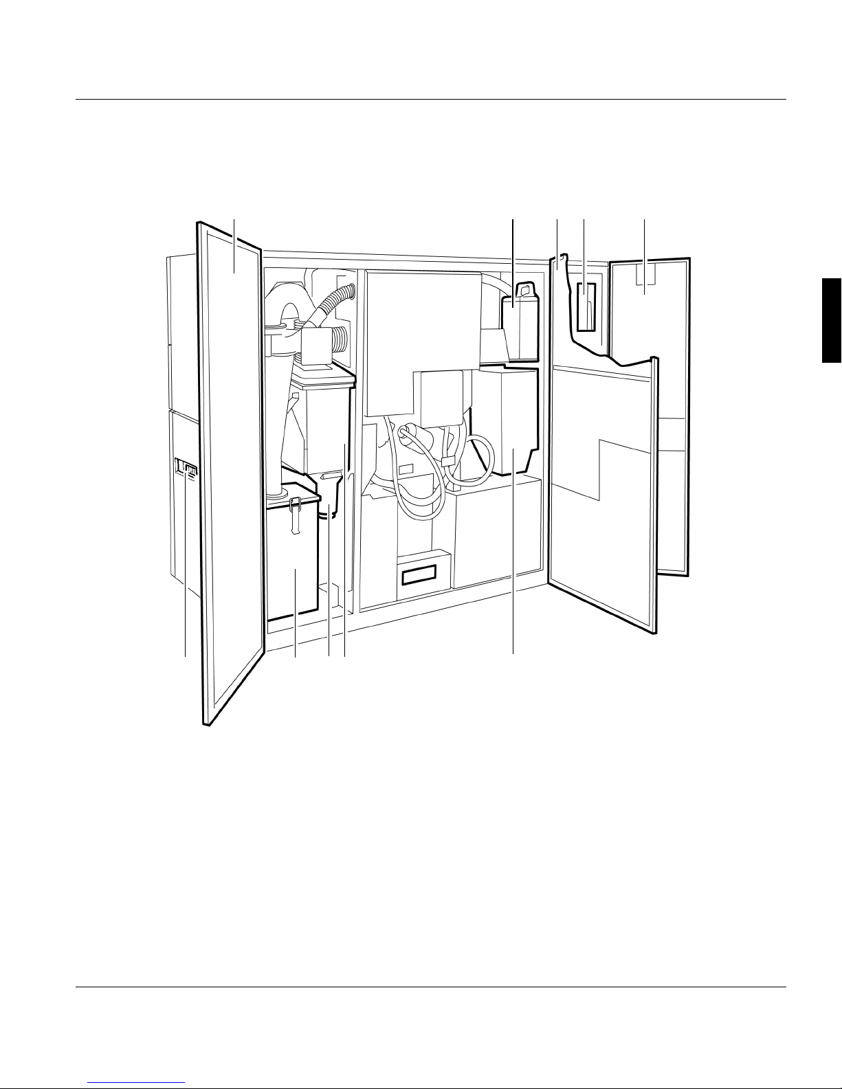
3.2.2 Internal view
A29246-X20-X-4-7680 / fa301.fm 45
3.2.2 Internal view
Front side
123 4 6 791011 125 8
1316 1415
17181920

3.2.2 Internal view
46 A29246-X20-X-4-7680 / fa301.fm
1 side door of fuser station
2 Stacker operator panel
3 Fuser station
4 Front door of fuser station
5 Paper transporter
6 Cover hood
7 Transfer corotron cartridge
8 Photoconductor drum
9 Discharge corotron cartridge
10 Cleaning brush
11 Operator panel on paper transporter
12 Touchscreen operator panel
13 Floppy disk drive
14 Charge corotron cartridges
15 Front right door
16 Developer station
17 Front left door
18 Rocker
19 Stacker top
20 Stacker tray
3.2.2 Internal view
A29246-X20-X-4-7680 / fa301.fm 47
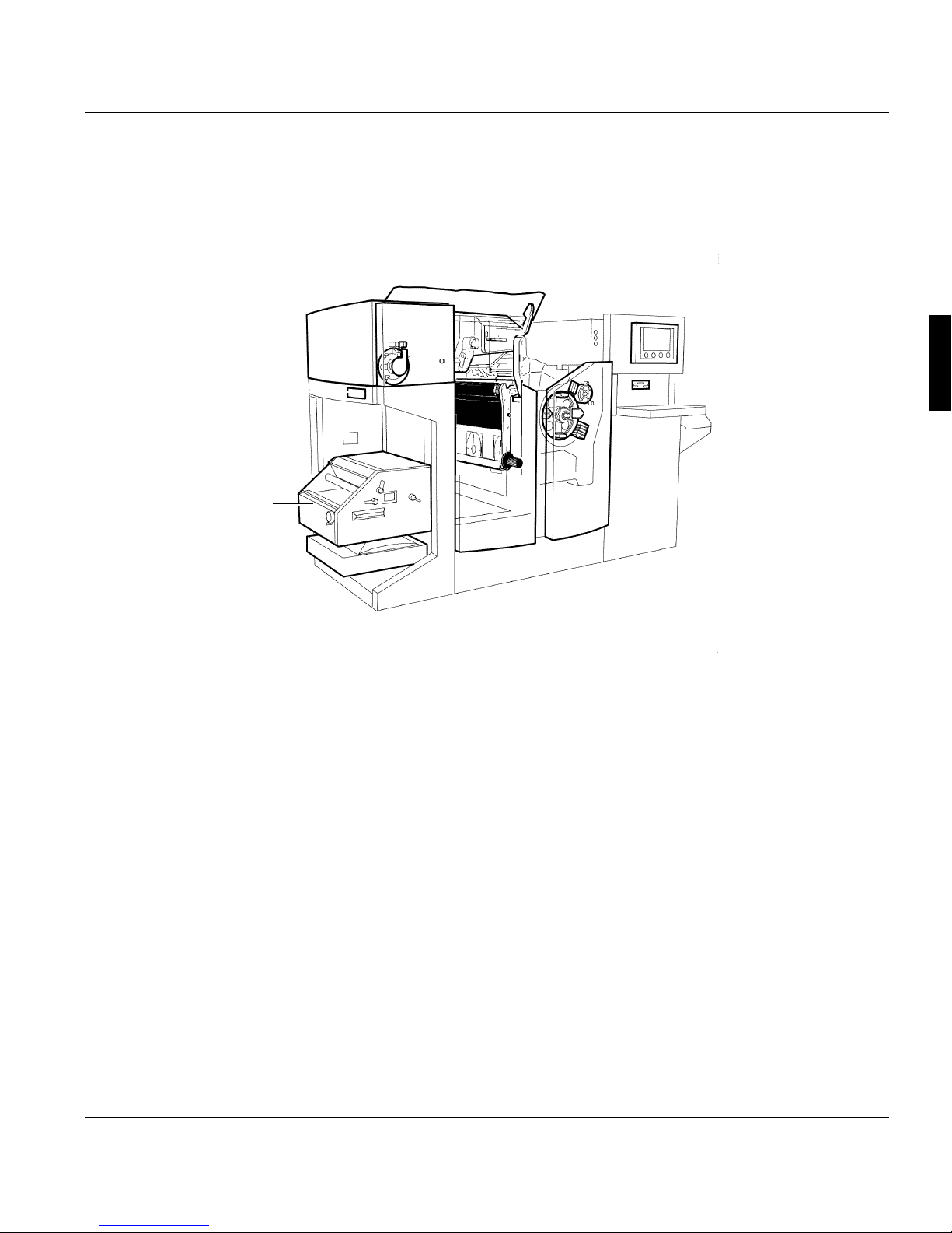
Rear
1 Back left door
2 Fuser oil container
3 Back center door
4 Fuser station
5 Back right door
6 Container for toner supply bottle
7 Container for fine filter
8 Toner dust indicator
9 Container for waste toner bottle
10 Main circuit breaker
1 2 3 4 5
68910 7

3.2.3 Toner bottle identification
48 A29246-X20-X-4-7680 / fa301.fm
3.2.3 Toner bottle identification
Toner bottle identification ensures that the toner bottle and toner box are assigned correctly
and unambiguously to the developer station. A plausibility check also prevents incorrect
settings on the developer station.
For this purpose, each toner bottle is equipped with a transponder for toner identification.
Transponder data is read by a reader and this information is analyzed by the printing
system.
1 Toner bottle
2 Transponder
3 Reader
4 Toner bottle holder
When a toner bottle with the correct toner type is identified, toner is sucked from the toner
bottle into the developer station toner boxes.
To prevent soiling of the developer stations and damage to the printing system, the printing
process is paused at print start, if:
• a toner bottle with an incorrect toner type is identified, or
• the toner bottle cannot be identified at all (because either no toner bottle is inserted or the
transponder on the toner bottle is faulty or not missing, or the reader is faulty).
Important
In both cases, a query is displayed on the operator panel asking whether printing
should continue regardless. If this query is confirmed, toner continues to be sucked
from the toner bottle into the developer station toner box. Soiling of the developer
stations and damage to the printing system cannot be ruled out however.
1
2
3
4

3.2.3 Toner bottle identification
A29246-X20-X-4-7680 / fa301.fm 49
The most important toner data and the current fill level can be found in the operator panel
in menu <Replace consumables> <Toner bottle identification>, e. g.:
Display Description
Toner Displays the ID of the toner used.
The message "unknown" indicates that the toner bottle is not
equipped with a transponder.
Fill level Displays whether there is still toner in the toner bottle.
Feed counter Displays the current number of feed cycles from the toner bottle.

3.3 Operating elements
50 A29246-X20-X-4-7680 / fa301.fm
3.3 Operating elements
This section contains information on the following topics:
3.3.1 Operator panel on paper transporter >>> page 50
3.3.2 Stacker operator panel >>> page 51
3.3.1 Operator panel on paper transporter
This operator panel can be accessed by opening the printing system cover hood. It has
three keys for moving the paper web.
Key Function
EJECT moves the paper web at print speed while the key is pressed.
The paper web is not printed.
Requirement:
• This function can only be executed in "Stop" status.
ADVF (ADVance Forward)
moves the paper slowly forwards while the key is being pressed. The paper
speed increases the longer you press the button.
Requirement:
• This function can only be executed in "Stop" status.
ADVR (ADVance Reverse)
moves the paper slowly backwards while the key is being pressed. The paper
speed increases the longer you press the button. The backwards movement
is restricted to a maximum of five steps.
Requirement:
• This function can only be executed in "Stop" status.
3.3.2 Stacker operator panel
A29246-X20-X-4-7680 / fa301.fm 51
3.3.2 Stacker operator panel
The stacker is only available as an option for the printing system.
1 Stacker operator panel
2 Stacker
2
1

3.3.2 Stacker operator panel
52 A29246-X20-X-4-7680 / fa301.fm
Stacker operator panel
Pos. Key Function
1 READY Switches the printing system from "Stop" or "Error" modes to ready
mode.
If no error condition is present, the green indicator lamp lights up.
Requirements:
• No errors present
• Controller and system control are ready
2 EJECT moves the paper web at print speed while the key is pressed.
Depending on how long this key is pressed, single or several pages
can be advanced.
The yellow NPRO key light and the red STOP key light come on during
this time. The paper path always stops at the beginning of the paper
depending on the selected form length.
The paper web is not printed. Pages already printed are fused.
Requirement:
• This function can only be executed in "Stop" status.
1 of 2
12345678
91011 12

3.3.2 Stacker operator panel
A29246-X20-X-4-7680 / fa301.fm 53
3 switches on the tension rollers in the stacker top. Pressing the key
again deactivates them.
After a period of 10 seconds, the tension rollers are automatically
powered down (not while paper is being inserted).
This key has no function during the preparation phase of the printing
system.
Requirement:
• This function can only be executed in "Stop" status.
4 completely lowers the stacker tray slide and deactivates it. This is
necessary when stacking very short forms.
The indicator light above lights up.
Pressing the key again - and every new paper insertion - reactivates
the stacker tray slide, which improves stacker behavior even for large
stack heights. The associated indicator lamp goes out.
5
6
Raises and/or lowers the stacker top.
Pressing the key again before the end position is reached stops the
movement.
7 C-EJECT Pressing this key will carry out an EJECT operation for twin and/or
triplex operation.
8 STOP switches the printing system to the "Stop" status
or
cancels current function
The orange indicator light above the key lights up and the green
READY indicator light goes out. "Not ready" is displayed in the basic
menu.
Before the printing system stops, the pages prepared on the PC drum
are transferred to the paper. The paper stops at the start of a page.
Characters on the paper between paper transporter and fuser station
are not yet fused.
The printing system is made operational again by pressing the
READY key.
Pos. Key Function
2 of 2

3.3.2 Stacker operator panel
54 A29246-X20-X-4-7680 / fa301.fm
LED display
Pos. Indicator lamp Function
9 READY This green indicator lamp lights up if no error condition is present
when the READY key is pressed.
10 EJECT The yellow indicator lamp lights up while the paper is being advanced
after pressing the EJECT or NPRO keys.
11 The indicator lamp under this icon lights up after the key for lowering
or raising the stacker tray slide in the stacker tray is pressed.
12 STOP The orange indicator lamp lights up after pressing the STOP key.

3.4 Paper specifications
A29246-X20-X-4-7680 / fa301.fm 55
3.4 Paper specifications
This section contains information on the following topics:
3.4.1 General information >>> page 55
3.4.2 Paper types >>> page 55
3.4.3 Paper handling >>> page 56
3.4.1 General information
To ensure maximum system availability, the paper must comply with the paper
specifications and be stored in an environment with suitable ambient conditions.
Non-compliance with the paper specifications can cause damage to the printing system and
may also result in the release of substances from the paper which can contaminate the
environment or have a detrimental effect on health. Océ Printing Systems GmbH accepts
no liability for such damages.
The printing system is designed to process a wide range of paper types. However, the
operational properties of the printing system and the print quality also depend on factors
such as:
• Paper quality
• Grammage
• Moisture content
• Dimensional stability
• Smoothness, etc.
3.4.2 Paper types
All media that comply with the requirements of the electrophotographic printing method can
be used in all specified formats and paper weights.
Using other paper qualities may result in reduced operational results, lower availability and
possibly also higher usage of consumables and expendables.
Note
When using continuous rollpaper, observe the operating instructions for the paper preand post-processing devices.

3.4.3 Paper handling
56 A29246-X20-X-4-7680 / fa301.fm
3.4.3 Paper handling
The climate (temperature and relative humidity) in the storeroom or processing room is of
major importance in ensuring optimum paper processing. Unsuitable conditions can, for
example, give the paper an excessive curl, make it bumpy, or alter its electrical resistance.
The paper should be transported and stored in a suitable manner.
In order not to impair the quality of the supplied paper, observe the following:
• Store the paper in the supplied packaging until use.
• Do not store paper on the floor or next to walls, or in the vicinity of water pipes, radiators,
ventilators, windows (sunlight) etc.
• Do not store paper in rooms in which the ambient conditions are subject to constant
change.
• Before you use the paper, store it (in its packaging) near the printing system for a few
days if possible, or at least for 24 hours.
• Do not unpack more paper than you need.
• Always store open packs on the top of your supply stacks, and use open packs first. If you
have to store open packs over a longer period of time, cover the paper with protective film.

3.5 Paper feed options
A29246-X20-X-4-7680 / fa301.fm 57
3.5 Paper feed options
1 Photoconductor drum
2 LED print head
3 External paper feed
4 Paper feed from behind
5 Internal input tray
6 Paper feed from the front

3.5 Paper feed options
58 A29246-X20-X-4-7680 / fa301.fm

4 Operator panel
A29246-X20-X-4-7680 / fa400.fm 59
4 Operator panel
4.1 Overview
This section describes the individual areas of the operator panel with the most important
icons and buttons. You will also find out how to navigate through the menus, set
parameters, and start and end the replacement of consumables and expendables.
You will find information on the following topics:
4.2 Operator panel description >>> page 60
4.3 Using the operator panel >>> page 80
Note
Detailed information on all menus and operating elements is also available directly in
the operator panel via the context-sensitive Direct Help. The context-sensitive Direct
Help can be called up by selecting the relevant menu or operating element and then
pressing the F1 key.
If necessary, all the requirements for setting the respective parameters are also listed
in the context-sensitive Direct Help. Specified standard settings and values are
denoted in bold.

4.2 Operator panel description
60 A29246-X20-X-4-7680 / fa400.fm
4.2 Operator panel description
The operator panel is divided into the following areas:
1 see section 4.2.1 Toolbar, page 61
2 see section 4.2.2 Menu tree, page 71
3 see section 4.2.3 Menu display, page 79
1
2
3

4.2.1 Toolbar
A29246-X20-X-4-7680 / fa400.fm 61
4.2.1 Toolbar
The toolbar can be used to access important functions in the printing system quickly and to
switch directly to frequently used menus.
1 see section 4.2.1.1 Buttons and displays in the left-hand area, page 62
2 see section 4.2.1.2 Center area buttons and displays, page 64
3 see section 4.2.1.3 Frame toolbar, page 69
1
2
3

4.2.1.1 Buttons and displays in the left-hand area
62 A29246-X20-X-4-7680 / fa400.fm
4.2.1.1 Buttons and displays in the left-hand area
Note
The following buttons can be operated both with the mouse and from the touchscreen.
Button Function
switches the printing system back from "Stop" or "Error" status to
operational status.
Requirements:
• No errors present
• Controller and system control are ready
• switches the printing system to the "Stop" status
or
cancels current function
Non Process Run Out
transports the last printed pages out of the printing system.
The printed pages are fused.
Requirement:
• This function can only be executed in "Stop" status.
Display Function
Indicates that print data has been transferred from the host to a
printing system.
1 of 2

4.2.1.1 Buttons and displays in the left-hand area
A29246-X20-X-4-7680 / fa400.fm 63
Standard display (no current print data from the host).
Indicates that the controller is performing a restart.
If this message is displayed, print data transfer from the host
must be repeated as it cannot be guaranteed that the last pages
were correctly transferred and fused before the error occurred.
Standard display (no controller restart).
Display Function
2 of 2

4.2.1.2 Center area buttons and displays
64 A29246-X20-X-4-7680 / fa400.fm
4.2.1.2 Center area buttons and displays
The current printer status is displayed in the center area of the toolbar. The individual
displays have different background colors depending on the printer status:
• Green: the printer is printing or is ready to print
• Red: error
• Gray: all other printer states
The most important status displays are described below:
Display Function
The printing system is ready to print, there are no
error messages.
Normal print operation.
The printing system is switching from "Stop"
status to “Ready” status.
An error message is displayed. The error must be corrected, otherwise printing cannot
continue.
All current messages are also displayed in the <Errors and warnings> menu (see section
8.2 Processing messages on the operator panel, page 338).
1 of 3

4.2.1.2 Center area buttons and displays
A29246-X20-X-4-7680 / fa400.fm 65
The printing system is switching to "Stop" status.
The printing system is being initialized and is not
yet ready for printing.
The printing system is stopping to clean the
corotrons.
The printing system is being prepared for power
off. A shut-down setup is being written, all
components are being exited.
A setup is being loaded or saved.
Consumable replacement is being carried out.
Display Function
2 of 3

4.2.1.2 Center area buttons and displays
66 A29246-X20-X-4-7680 / fa400.fm
The printing system is in "Stop" status.
The following icon is displayed when a message
from the data stream has also been transferred:
The complete message is displayed on the "Job
Preparation" tab in the <Setup> menu.
The printing system is being prepared for restart
and will then be rebooted.
The twin printing system is in the "Stop" status.
Printing is interrupted because pre/post processing has stopped. The printing process will
continue when pre/post processing is ready.
Display Function
3 of 3

4.2.1.2 Center area buttons and displays
A29246-X20-X-4-7680 / fa400.fm 67
Button Function
Switches to the <Emulations> menu.
The following buttons are available here under
"Job control":
Cancels the current print job.
The data in the page buffer is erased.
Requirement: The printing system is in "Stop"
status.
Only in PCL mode and only if the printing system
is in "Not ready" status:
Cancels the current print job. The data in the
page buffer is still printed out.
Only in I-Mode:
deletes the existing data in the printing system.
Performs a test print with the entered number of
pages.
Switches to the <Channels> menu.
The following buttons are available here:

4.2.1.2 Center area buttons and displays
68 A29246-X20-X-4-7680 / fa400.fm
Activates the channel.
The clutch icon is closed.
Deactivates the channel.
The clutch icon is opened.
During the time needed to activate/deactivate a
channel, the clutch icon is shown in yellow.
Flashes when there is an error message.
Flashes when there is a warning.
Flashes when there is information.
When there is no error message, warning or
information, this button is hidden.
Clicking this button switches to the <Errors and
warnings> menu (see section 8.2 Processing
messages on the operator panel, page 338).
Indicates that remote access is activated. This
allows the service center to perform a remote
diagnosis during printer operation.
The button appears only when a remote
diagnosis has been arranged. Clicking the
button deactivates remote access directly
without having to go through the menu.
Also indicates that remote access is activated.
Button Function

4.2.1.3 Frame toolbar
A29246-X20-X-4-7680 / fa400.fm 69
4.2.1.3 Frame toolbar
On the right is the higher-level frame toolbar for the complete printing system. You can use
these buttons to quickly access higher-level functions in the printing system and to switch
directly to frequently-used menus.
Indicates that remote access is not activated.
Clicking the button activates remote access
directly without having to go through the menu.
Switches to the <Consumables counter> menu.
This menu displays the current counter values
and the respective limit values for all
consumables and expendables in the printing
system.
Switches to the <Service ticket> menu.
This menu displays all the data required to notify
the relevant service center.
Button Function
Switches to the <User profile> menu.
The language of the operator panel can be changed in this menu.
Indicates that the presently logged-on user possesses the access ticket.
Clicking releases the access ticket directly without going through the
menu.
Indicates that the access ticket is released for other other users.
Clicking requests the access ticket directly without going through the
menu.
Opens Help.
1 of 2
Button Function

4.2.1.3 Frame toolbar
70 A29246-X20-X-4-7680 / fa400.fm
Switches to the <Change user> menu.
Users can be logged on and off in this menu.
Displays the user currently logged on.
Powers down the printing system if the print is confirmed.
This button can be operated both with the mouse and from the
touchscreen.
Switches from any sub-menu directly to the main menu of the printing
system or the UP3I manager.
Button Function
2 of 2

4.2.2 Menu tree
A29246-X20-X-4-7680 / fa400.fm 71
4.2.2 Menu tree
All the menus can be accessed via the menu tree.
The menus are structured into main groups, e. g.:
• [00] <General>
You can define the user settings valid for the entire printing system in these menus.
• [02] <VarioStream>
You can set the relevant parameters for the "VarioStream" printing system in these
menus.
• [FF] <Paper Path Manager>
In these menus you can get an overview of all UP3I-capable devices of the printing
system.
• Devices for post-print processing
The numbers before the main groups are required to identify the devices in the printing
system.
Clicking the switches in the menu tree lets you show or hide other menu levels, e. g.:

4.2.2 Menu tree
72 A29246-X20-X-4-7680 / fa400.fm
You can switch directly to the main menu from any menu. Click the following button in the
toolbar for this purpose:
Further information:
4.2.2.1 Menus <General> >>> page 73
4.2.2.2 Menus<VarioStream> >>> page 74
4.2.2.3 Menus <Paper Path Manager> >>> page 78
Note
The menus displayed in the menu tree depend on the respective authorizations for the
individual user categories.
This documentation describes all menu options set up as default for the user
categories "Operator" and "Key Operator".

4.2.2.1 Menus <General>
A29246-X20-X-4-7680 / fa400.fm 73
4.2.2.1 Menus <General>
Note
Menus that can only be opened by the user "Key operator" as standard are shown in
italics in the table.
Menu Description
General The sub-menus contain global settings for users,
access tickets and screen cleaning for the entire
printing system
User management The sub-menus contain the user settings relating to
the Key Operator
Add user Add new users or user templates
Delete user Delete users or user templates
Edit user Settings for:
Password / authorization level
User rights (for menus / for elements)
User profile (language)
User The sub-menus contain the user settings relating to
the operator
Change user Log a user on or off
User profile Select the operator panel language
Access ticket Request or release the access ticket
Network management Overview of all computers with access to the printing
system
Tools Enable screen cleaning during printing

4.2.2.2 Menus<VarioStream>
74 A29246-X20-X-4-7680 / fa400.fm
4.2.2.2 Menus<VarioStream>
Menu Description
<VarioStream> Displays basic information on the printing
system:
• Number of all 12" pages previously printed in
user operation.
• Setup currently loaded
• Current print job
• Name and serial number of the printing system
• Available emulations
The sub-menus contain all settings and displays
relating to the "VarioStream 7000" printing
system.
<Displays> The sub-menus contain displays on current error
and warning messages and various counters on
the printing system
<Errors and warnings> Displays the current error and warning
messages and information
<General counters> Displays page counter, warm-up time, user
counters and toner types
<Consumables counter> Displays the current counter values and the
relevant limit values for all consumables and
expendables of the printing system
<Consumables history> Displays all replacement procedures for all
replaced consumables/expendables, each with
time and counter reading
<Configuration> The sub-menus contain the parameters for
setting the printing system
<Paper> The sub-menus contain the parameters for the
paper webs to be printed
<Dimensions> Enter and display paper parameters
<Properties> Enter and display paper properties
<Shift> Enter and display offset parameters
<Marks> Enter and display mark parameters
<Calibrate mark sensor> Procedure for setting up mark sensors
1 of 4

4.2.2.2 Menus<VarioStream>
A29246-X20-X-4-7680 / fa400.fm 75
<Printing system> The sub-menus contain specific parameters for
the printing system
<Speed> Select printer speed
<Paper path> Settings for paper brakes, automatic paper
ejection and paper end
<Stacker> Settings for stacker properties
<Operating mode> Select operating mode
<System functions> Settings for system functions
<Conversion> Select configuration for the printing system
<Print parameters> The sub-menus contain specific parameters for
the printing system
<Fusing quality> Settings for wrapping, fusing temperature and
oiling
<Print quality> Contrast setting
<Color management> Settings for colors in the printing system
<Emulations> Displays emulations, buttons for job control,
restarting, and PCL settings
<General> Select and enter general cross-emulation
settings
<Color>
(optional)
Settings for background printing for color printing
<Cut sheet Emulation> Set and display parameters for printing single
sheets
<SNMP configuration> SNMP (= Simple Network Management
Protocol) is a network protocol that is used to
manage TCP/IP networks. External programs
can access the PrinterMIB via SNMP
<I-Mode> The sub-menus contain the parameters for I-
Mode
<Properties> Settings for font capture, data resolution and
logical page extension
<Continuous feed> Settings for specific parameters for continuous
printing in I-Mode
Menu Description
2 of 4

4.2.2.2 Menus<VarioStream>
76 A29246-X20-X-4-7680 / fa400.fm
<Standard resources> Select and display standard resources for I-
Mode
<Resource management> Install new resources or
delete existing resources
<PCL mode> The sub-menus contain the parameters for PCL
mode
<Properties> Settings for job separation, alignment, print
mode, number of copies and lines per forms
overlay
<Continuous feed> Settings for specific parameters for continuous
printing in PCL mode
<Standard resources> Select and enter standard resources for PCL
mode
<Resource management> Install new resources or
delete existing resources
<C/E mode> The sub-menus contain the parameters for C/E
mode
<Properties> Set general properties for C/E mode, specific
parameters for the EFO values, for 2-up and
print orientation
<Channel extensions> Settings for specific parameters for channel
extensions
<Channels> Displays the current channel settings and
settings for channel control
<Channel A / B / C> Select and enter parameters for channel A
<Channel A / B / C> Select and enter parameters for channel B
<Channel A / B / C> Select and enter parameters for channel C
<Special functions> The sub-menus contain special parameters for
the printing system
<Clean corotrons> Cleans all corotrons in the printing system
<Clean LED print head> Cleans the LED print head
<Operator trace> Write an error log
<Service ticket> Display all data required to notify the service
center
Menu Description
3 of 4

4.2.2.2 Menus<VarioStream>
A29246-X20-X-4-7680 / fa400.fm 77
<Remote diagnostics> Activate or deactivate remote access by the
service
<Setup> Display and edit the globally valid print job
setups
<Setup channel A / B / C> Display and edit setups for channel A
<Setup channel A / B / C> Display and edit setups for channel B
<Setup channel A / B / C> Display and edit setups for channel C
<Replace consumables> The sub-menus contain the procedures for
replacing consumables and expendables
<Replace active filter> Procedure for replacing the active filter
<Replace pressure roller> Procedure for replacing the pressure roller.
<Replace corotrons> Procedure for replacing the transfer, charge and
discharge corotrons
<Replace developer> Procedure for draining or filling the developer in
the developer station
<Fill developer> Procedure for filling the developer in the
developer station
<Replace heater> Procedure for replacing the heater
<Replace fine filter> Procedure for replacing the fine filter
<Replace fuser oil bottle> Procedure for replacing the fuser oil bottle.
<Replace fuser roller> Procedure for replacing the fuser roller
<Replace photoconductor drum> Procedure for replacing the photoconductor
drum
<Run in photoconductor drum> Procedure for inserting the photoconductor
drum
<Replace cleaning brush> Procedure for replacing the cleaning brush
<Replace cleaning belt> Procedure for replacing the cleaning belt
<Replace toner bottle> Procedure for replacing the toner bottle
<Fill toner box> Procedure for filling the toner box
<Replace waste toner bottle> Procedure for replacing the waste toner bottle
<Toner bottle identification> Displays information on the toner used
<Replace transfer roller> Procedure for replacing the transfer roller
<Replace transfer foil> Procedure for replacing the transfer foil
Menu Description
4 of 4

4.2.2.3 Menus <Paper Path Manager>
78 A29246-X20-X-4-7680 / fa400.fm
4.2.2.3 Menus <Paper Path Manager>
Note
You can find information on the Paper Path Manager in the printing system operator
panel in Help.

4.2.3 Menu display
A29246-X20-X-4-7680 / fa400.fm 79
4.2.3 Menu display
This area shows the menu selected in the menu tree. You can select or set all parameters
required to operate the printing system here.
Note
Detailed information on all menus and operating elements is also available directly in
the operator panel via the context-sensitive Direct Help.
The context-sensitive Direct Help can be called up by selecting the relevant menu or
operating element and then pressing the F1 key.
If necessary, all the requirements for setting the respective parameters are also listed
in the context-sensitive Direct Help. Specified standard settings and values are
denoted in bold.

4.3 Using the operator panel
80 A29246-X20-X-4-7680 / fa403.fm
4.3 Using the operator panel
This section contains information on the following topics:
4.3.1 Managing user settings (key operator) >>> page 81
4.3.2 Managing user settings (operator) >>> page 84
4.3.3 Setting parameters >>> page 87
4.3.4 Starting and completing the replacement of consumables and expendables >>> page
90

4.3.1 Managing user settings (key operator)
A29246-X20-X-4-7680 / all_allg3.fm 81
4.3.1 Managing user settings (key operator)
As a key operator, you can normally make the following user settings:
4.3.1.1 Adding users >>> page 81
4.3.1.2 Deleting users >>> page 82
4.3.1.3 Editing users >>> page 82
4.3.1.1 Adding users
Note
A logged-on user can only create, delete or edit users who have a lower authorization
level. Users with the same or a higher authorization level are not listed in the selection
lists.
Proceed as follows:
1. Click the <General> <User management> <Add user> menu.
2. Select user:
• If an entire user group is to be added:
select the entry "Template" under "Type"
enter a name for the new user group under "Name."
• If a specific user is to be added:
select the entry "User" under "Type"
enter a name for the new user under "Name."
3. Click on the following button:

4.3.1.2 Deleting users
82 A29246-X20-X-4-7680 / all_allg3.fm
4.3.1.2 Deleting users
4.3.1.3 Editing users
Proceed as follows:
1. Click the <General> <User management> <Delete user> menu.
2. Select user:
• If a whole user group is to be deleted:
select the entry "Template" under "Type"
select the desired template under "Name."
• If a specific user is to be deleted:
select the entry "User" under "Type"
select the desired user under "Name."
3. Click on the following button:
Note
As standard, three user groups are predefined: Operator, Key Operator and Service.
Any changes made to their associated user profiles will be reset when a new operator panel version is installed. However, changes to profiles of individually created users will be unaffected by the installation.
Proceed as follows:
1. Click the <General> <User management> <Edit user> menu.
2. Select user:
• If the settings for an entire User group are to be edited:
select the entry "Template" under "Type"
select the desired template under "Name."
• If the settings for a specific user are to be edited:
select the entry "User" under "Type"
select the desired user under "Name."
3. Setting passwords and authorization levels for users >>> page 83
Releasing menus and elements for users >>> page 83
Presetting language for users >>> page 84

4.3.1.3 Editing users
A29246-X20-X-4-7680 / all_allg3.fm 83
Setting passwords and authorization levels for users
Releasing menus and elements for users
Proceed as follows:
1. Click on the "General" tab.
2. Enter the password and re-enter it identically under "Password confirmation".
The password may consist of any characters.
3. Set authorization level.
Authorization levels can only be changed to one level below that of the person editing
the level.
Proceed as follows:
1. Click on the "User Rights" tab.
2. Under "Menus" activate the checkboxes for the menus which are to be displayed for
the user in the menu tree.
If a menu is not to be displayed, deactivate the respective checkbox. This also prevents the user from accessing all subordinate menus.
3. Under "Elements" click the checkboxes in front of the control elements that are to be
editable for this user.
If an element is not to be editable:
deactivate the respective checkbox.
4. Click on the following button:

4.3.2 Managing user settings (operator)
84 A29246-X20-X-4-7680 / all_allg3.fm
Presetting language for users
4.3.2 Managing user settings (operator)
As an operator, you can normally make the following user settings:
4.3.2.1 Logging on as user and requesting the access ticket >>> page 85
4.3.2.2 Changing password >>> page 86
4.3.2.3 Changing language >>> page 86
Proceed as follows:
1. Click on the "User Profile" tab.
2. Select the desired language in the selection list.
3. Click on the following button:

4.3.2.1 Logging on as user and requesting the access ticket
A29246-X20-X-4-7680 / all_allg3.fm 85
4.3.2.1 Logging on as user and requesting the access ticket
To be able to set parameters on the operator panel, you must first log on as a user and then
request the access ticket.
The access ticket ensures that parameters are not set by different users at parallel operator
panels.
Note
If a user with a higher authorization level has already requested the access ticket, a
message will be displayed. From users with the same authorization level the access
ticket can be requested directly.
Proceed as follows:
1. Click the <General> <User> <Change user> menu.
2. Select the desired user in the selection list.
3. Enter password.
4. Click on the following button:
Only if several operator panels are connected to the printing system:
5. Click on the <General> <Access ticket> menu.
6. Click on the following button:
If the access ticket has already been requested, the button is deactivated.
Note
The access ticket can also be requested and released directly using the following buttons in the frame toolbar without going through the menu.

4.3.2.2 Changing password
86 A29246-X20-X-4-7680 / all_allg3.fm
4.3.2.2 Changing password
4.3.2.3 Changing language
Proceed as follows:
1. Click the <General> <User> <User profile> menu.
2. Click on the "Password" tab.
3. Enter the old password and then enter the new password twice.
The password may consist of any characters.
4. Click on the following button:
Proceed as follows:
1. Click the <General> <User> <User profile> menu.
2. Click on the "User Profile" tab.
3. Select the desired language in the “Language” selection list.
4. Click on the following button:

4.3.3 Setting parameters
A29246-X20-X-4-7680 / fa405.fm 87
4.3.3 Setting parameters
All parameters of the printing system can be set at the operator panel. The following
prerequisites must be given:
• The necessary rights are available. These rights are allocated by the respective "Key
Operator" in the <Edit user> menu (see section 4.3.1.3 Editing users, page 82).
• The access ticket for this operator panel is requested (see section 4.3.2.1 Logging on as
user and requesting the access ticket, page 85).
• The printing system is in "Stop" or "Error" status. When the printing system is running, the
parameters can only be checked but not reset.
The following steps must be carried out to set parameters:
4.3.3.1 Selecting settings and entering values >>> page 88
4.3.3.2 Apply or reset parameters >>> page 89

4.3.3.1 Selecting settings and entering values
88 A29246-X20-X-4-7680 / fa405.fm
4.3.3.1 Selecting settings and entering values
You can select predefined settings and values through various operating elements, such as
selection lists, option fields, checkboxes, slide controls, etc.
You can also enter new values in input fields via the keyboard.
Example: Entering the paper length
Proceed as follows:
1. Select unit for paper length
The first click opens the selection list, the second click
selects the unit.
2. Select the number via the slide control, or enter it into
the input field with the keyboard.

4.3.3.2 Apply or reset parameters
A29246-X20-X-4-7680 / fa405.fm 89
4.3.3.2 Apply or reset parameters
If you change parameters in a menu, you have to confirm these changes before switching
to another menu.
If you change to another menu without applying the changed parameters, the following
query is displayed:
Button Function
The parameters are applied.
The parameters are not applied; instead the previous parameters
are restored.
Button Function
The parameters are applied and the new menu opens.
The parameters are not applied; instead the previous parameters are
restored.
Then the new menu is opened.
The parameters are not applied.
The menu remains open.

4.3.4 Starting and completing the replacement of consumables and expendables
90 A29246-X20-X-4-7680 / fa405.fm
4.3.4 Starting and completing the replacement of consumables and expendables
The operator panel informs you about the current status of the printing system. Warning
and error messages indicate when consumables or expendables (= consumables/
expendables) have to be refilled or replaced.
You can also check the current counter status at any time in the <Consumables counter>
menu, e. g.:
Every time a consumable or expendable part is replaced, individual working steps must be
carried out on the operator panel.
Column Description
Status The usage period for this consumable/expendable is below the warning
value.
No action required.
The warning value for this consumable/expendable has been exceeded.
The consumable/expendable part should be replaced soon.
The accumulated value for this consumable/expendable has been
exceeded.
The consumable/expendable part must be replaced soon.
Counter Abbreviation for the relevant consumable/expendable.
Counter value Number of pages printed since the last replacement.
Unit The values displayed refer to A4 pages or to 12" pages.
Warning value A warning message appears if this value is reached.
End value An error message appears if this value is reached.

4.3.4 Starting and completing the replacement of consumables and expendables
A29246-X20-X-4-7680 / fa405.fm 91
Requirements:
• the user rights for replacing the developer are available
• the access ticket for this operator field is requested
• the printing system is in "Stop" or "Error" status, i.e. does not print
• no other change function is executed.
The following explains the procedure for starting and confirming the individual steps using
"Replace cleaning brush" as an example.

4.3.4 Starting and completing the replacement of consumables and expendables
92 A29246-X20-X-4-7680 / fa405.fm
Proceed as follows:
1. Click on the <Replace consumables> <Replace cleaning brush> menu.
2. A menu window is opened, which displays all the necessary steps, e. g.:
1 of 3

4.3.4 Starting and completing the replacement of consumables and expendables
A29246-X20-X-4-7680 / fa405.fm 93
3. Perform all the displayed steps in the given order.
Icons
The icons on the left-hand side show the type of the current step:
Answer a query at the operator panel.
Perform a mechanical adjustment of the printing system.
This step is carried out by the printing system without the operator's
involvement.
The icons on the right side indicate the progress:
This step is currently being executed.
The progress display is automatically moved forward for step types and
.
The progress display is not automatically moved forward for step type . To
display the details of the next step, you must switch to the next step by clicking
the mouse.
This step has not been performed yet and is still to be carried out.
This step was successfully completed.
This step was not completed successfully.
The steps are described in more depth under "Details".
Additional Help for the individual replacement procedures: see section 7 Replacing
consumables and expendables, page 225.
Proceed as follows:
2 of 3

4.3.4 Starting and completing the replacement of consumables and expendables
94 A29246-X20-X-4-7680 / fa405.fm
4. Complete replacement procedure.
As a result, the following will occur automatically:
• the message on the operator panel is deleted
• the replacement of the consumable/expendable is documented in the
<Consumables history> menu
• the consumable counter is reset.
Proceed as follows:
3 of 3

5 Operating the printing system
A29246-X20-X-4-7680 / fa500_pinfed.fm 95
5 Operating the printing system
5.1 Overview
This section explains how to power the printing system on and off and the procedure for
inserting, removing and replacing the paper web.
You will find information on the following topics:
5.2 Powering on the printing system >>> page 96
5.3 After print stop, switch the printing system back to "Ready" >>> page 99
5.4 Inserting paper (pinfed) >>> page 100
5.5 Setting the external paper feed lever >>> page 120
5.6 Settings when changing paper (pinfed) >>> page 121
5.7 Removing the paper stack >>> page 131
5.8 Working with setups >>> page 133
5.10 Converting the printing system >>> page 162
5.12 Powering off the printing system >>> page 173

5.2 Powering on the printing system
96 A29246-X20-X-4-7680 / fa501.fm
5.2 Powering on the printing system
Note
If the optional High Temperature Kit is used, the external recooling system must be
powered on before powering on the printing system:
Proceed as follows:
1. Turn the main circuit breaker on the
right narrow side upwards to Position I.
2. Press the POWER ON button.
After pressing the POWER ON button,
wait until the booting information
appears on the operator panel.
During the boot phase, different
messages appear on the operator
panel in the basic menu.
1 of 3

5.2 Powering on the printing system
A29246-X20-X-4-7680 / fa501.fm 97
3. Only if an SRA boot error appears in
the operator panel or when rebooting
is required.
4. The printing system is initialized (takes approx. 6 minutes). The printing system's
current status information is displayed on the operator panel.
5. Activate the desired channel on the operator panel. To do this, click the following
button:
The <Channels> menu is displayed.
To activate the channel, click on the following button:
During the time needed for activation, the clutch icon is shown in yellow. An activated
channel is represented by the following icon:
6. Insert paper web.
7. Set up a print job.
Proceed as follows:
2 of 3

5.2 Powering on the printing system
98 A29246-X20-X-4-7680 / fa501.fm
8. Click on the following button:
The printing system is in "Ready" status.
Proceed as follows:
3 of 3

5.3 After print stop, switch the printing system back to "Ready"
A29246-X20-X-4-7680 / fa501.fm 99
5.3 After print stop, switch the printing system back to "Ready"
A print stop may have the following causes:
• The controller has run out of data.
The printing system is in "Ready" status and continues printing automatically as soon as
print data is available again.
• The STOP key was pressed on the operator panel.
The printing system is in "Stop" status.
To switch the printing system back to "Ready":
• The printing system was stopped by an error message.
Information on switching to ready after a stop caused by an error: see section 8.2.2
Continuing printing after errors have been corrected, page 341.
Proceed as follows:
1. Click on the following button:
Print operation continues without any impairment to print or fusing quality. The
temperature of the fuser station decreases in stages with longer standby times. For
this reason, the fuser station may first have to be reheated to its operating
temperature. Depending on the type of paper, this may take up to 30 seconds.

5.4 Inserting paper (pinfed)
100 A29246-X20-X-4-7680 / fa502_pinfed.fm
5.4 Inserting paper (pinfed)
To insert paper, the printing system must be powered on, i.e. the main circuit breaker is in
position I and the POWER ON key is activated. The paper can be fed either via the internal
input tray or via the external central paper feed.
Proceed as follows:
1. Lift up cover hood.
2. Open the left and right door at the front of the printing system.
3. Only if replacing the paper stack before paper end click on the following button:
4. Cut the paper in the input tray in the
paper stack area.
 Loading...