


Océ | Operating Manual
Océ
Océ VarioPrint 5000

...and training?
We also offer courses at our Training Center for the product described below.
Information:
Telephone +49 8121 72 3940
Fax +49 8121 72 3950
Océ Printing Systems GmbH
ITC
Postfach 1260
85581 Poing
Germany
Edition August 2005
Order no. A29246-X17-X-4-7680
Copyright © Océ Printing Systems GmbH 2004, 2005
The products Océ VarioStream
trademark.
All rights reserved, including rights of translation, reprinting, reproduction by copying or any other method. Offenders
will be liable for damages.
All rights, including rights created by patent grant or registration of a utility model or design, are reserved.
Delivery subject to availability; right of technical modifications reserved.
®
, Océ Web Buffer 9000®, Océ VarioPrint® and Océ CustomTone® are protected by

Notes on the printing system
documentation
1
Safety
Description of the printing system
Operator panel
Operating the printing system
Cleaning the printing system
2
3
4
5
6
Replacing consumables and
expendables
Correcting errors
Appendix
Index
7
8


Table of Contents
1 Notes on the printing system documentation ..................................................... 1
1.1 Overview.................................................................................................................... 1
1.2 Signposts .................................................................................................................. 2
1.3 Using "Help" .............................................................................................................. 3
1.3.1 Contents ...................................................................................................... 4
1.3.2 Index ........................................................................................................... 5
1.3.3 Search ........................................................................................................ 6
1.3.4 Direct Help ................................................................................................. 7
1.4 Symbols in the text ................................................................................................... 9
1.5 Symbols in diagrams and illustrations .................................................................... 10
1.6 Other documents .................................................................................................... 12
1.7 Manufacturer of the printing system ....................................................................... 12
1.8 Statutory requirements ........................................................................................... 13
Table of Contents
2 Safety...................................................................................................................... 15
2.1 Overview.................................................................................................................. 15
2.2 Intended Purpose ................................................................................................... 16
2.3 Operating and service clearance ............................................................................ 17
2.4 Flagging of safety directives ................................................................................... 18
2.5 Warning and Information signs ............................................................................... 19
2.6 Accident and damage prevention ............................................................................ 21
2.6.1 Personal Representations ......................................................................... 21
2.6.2 Operation ................................................................................................. 22
2.6.2.1 Operator..................................................................................... 22
2.6.2.2 Safety covers ............................................................................ 23
2.6.2.3 Assemblies ................................................................................ 23
2.6.2.4 Cleaning .................................................................................... 24
2.6.2.5 Foreign bodies, noises .............................................................. 24
2.6.2.6 Cooling, heat ............................................................................. 24
2.6.2.7 Consumables and expendables................................................. 25
2.6.2.8 Optical wave guide .................................................................... 25
2.6.2.9 Laser .......................................................................................... 25
2.6.2.10 Remote control via LAN ............................................................. 25
A29246-X17-X-4-7680 / do_baIVZ.fm

Table of Contents
2.7 Safety regulations and standards ........................................................................... 27
3 Description of the printing system ...................................................................... 29
3.1 Overview.................................................................................................................. 29
3.2 Device overview ...................................................................................................... 30
3.3 Operating elements ................................................................................................ 36
3.4 Paper path ............................................................................................................... 39
3.5 Interposer ................................................................................................................ 45
2.6.3 Assembly and installation ......................................................................... 25
2.6.4 Transport .................................................................................................. 26
2.6.5 Repairs ..................................................................................................... 26
2.6.6 Fire ........................................................................................................... 27
2.6.7 Disposal .................................................................................................... 27
3.2.1 Front view.................................................................................................. 31
3.2.2 Front view of VP5000 advanced ............................................................... 32
3.2.3 Internal view .............................................................................................. 33
3.2.4 Rear view .................................................................................................. 34
3.2.5 Rear view of VP5000 advanced ................................................................ 35
3.3.1 Operating controls on the front of the housing .......................................... 36
3.3.2 Operating controls in the printing system .................................................. 38
3.4.1 Simplex printing......................................................................................... 39
3.4.2 Duplex printing .......................................................................................... 40
3.4.3 Simplex printing with two colors ................................................................ 41
3.4.4 Duplex printing with two colors .................................................................. 42
3.4.4.1 Printing on the front side with two colors ................................... 42
3.4.4.2 Printing on the back side with the first color............................... 43
3.4.4.3 Printing on the back side with the second color ......................... 44
4 Operator panel ...................................................................................................... 47
4.1 Overview.................................................................................................................. 47
4.2 Operator panel description ...................................................................................... 48
4.2.1 Toolbar of VarioPrint ................................................................................ 49
4.2.1.1 Buttons and displays in the left-hand area ................................. 50
4.2.1.2 Center area buttons and displays .............................................. 51
4.2.1.3 Frame icon bar........................................................................... 55
4.2.2 Menu tree .................................................................................................. 56
4.2.2.1 Menus <General> ..................................................................... 57
4.2.2.2 Menus <VarioPrint> ................................................................... 58
4.2.2.3 Menus <Paper Path Manager> ................................................. 62
4.2.3 Menu display ............................................................................................. 63
do_baIVZ.fm / A29246-X17-X-4-7680

Table of Contents
4.3 Using the operator panel ......................................................................................... 65
4.3.1 User settings by the Key Operator ........................................................... 66
4.3.1.1 Add user .................................................................................... 66
4.3.1.2 Delete user ................................................................................ 67
4.3.1.3 Edit user .................................................................................... 67
4.3.2 User settings made by the Operator ........................................................ 69
4.3.2.1 Log on as user and request an access ticket ............................ 70
4.3.2.2 Change Password ..................................................................... 71
4.3.2.3 Change language ...................................................................... 71
4.3.3 Configure parameters ............................................................................... 73
4.3.3.1 Select settings and enter values ................................................ 73
4.3.3.2 Applying or resetting parameters ............................................... 74
4.3.4 Working with wizards................................................................................. 75
4.3.4.1 Calling up and operating the Job wizard. ................................... 77
4.3.4.2 Calling up and operating the Paper wizard. ............................... 79
4.3.4.3 Calling up and operating the Format wizard. ............................. 80
4.3.5 Starting and confirming the replacement of a consumable or expendable82
5 Operating the printing system ............................................................................. 89
5.1 Overview.................................................................................................................. 89
5.2 Powering on the printing system ............................................................................. 90
5.3 Paper specifications ................................................................................................ 91
5.3.1 General information................................................................................... 91
5.3.2 Paper types ............................................................................................... 92
5.3.3 Climate and paper..................................................................................... 92
5.3.4 Paper handling .......................................................................................... 92
5.4 Refilling paper.......................................................................................................... 93
5.5 Removing paper from the output tray ...................................................................... 96
5.6 Replacing paper ...................................................................................................... 99
5.6.1 Paper formats and paper direction .......................................................... 100
5.6.2 Configuring the input tray ........................................................................ 102
5.6.3 Configuring the output tray ...................................................................... 106
5.6.4 Setting the fusing temperature ................................................................ 106
5.6.5 Setting the oiling quantity ........................................................................ 107
5.6.6 Solving stack problems ........................................................................... 108
5.6.6.1 Setting paddle force and paper pressure................................. 108
5.6.6.2 Setting down pressure ............................................................. 109
5.6.7 Paper formats and associated oiling rollers ............................................ 110
5.7 Setting up a print job.............................................................................................. 111
5.7.1 Print job details........................................................................................ 111
A29246-X17-X-4-7680 / do_baIVZ.fm

Table of Contents
5.8 Power off the printing system ................................................................................ 119
5.9 Printing with Two Colors ........................................................................................ 120
5.7.2 Select menu settings of the print job ....................................................... 112
5.7.2.1 Select print parameters ............................................................ 112
5.7.2.2 Select paper settings ............................................................... 114
5.7.2.3 Select input tray parameters .................................................... 116
5.7.2.4 Select output tray parameters.................................................. 117
5.7.3 Performing mechanical tasks for print job ............................................... 118
5.9.1 Preparing the Trolley ............................................................................... 121
5.9.2 Replacing fuser station ............................................................................ 126
5.9.2.1 Removing fuser station ............................................................ 127
5.9.2.2 Replacing fuser station on the trolley....................................... 130
5.9.2.3 Installing fuser station .............................................................. 135
5.9.3 Replace developer station ....................................................................... 139
5.9.3.1 Remove developer station ....................................................... 140
5.9.3.2 Replacing the Developer Station on the Trolley....................... 144
5.9.3.3 Install developer station ........................................................... 148
5.9.4 Menu settings for color printing ............................................................... 152
5.9.5 Automatic menu settings when using MICR............................................ 152
5.9.6 Calculation and input of shrinkage compensation ................................... 154
6 Cleaning the printing system ............................................................................. 159
6.1 Overview................................................................................................................ 159
6.2 Cleaning intervals .................................................................................................. 161
6.3 Daily cleaning ........................................................................................................ 162
6.3.1 Cleaning output trays .............................................................................. 162
6.3.2 Cleaning the developer station................................................................ 166
6.3.3 Cleaning the charge station..................................................................... 168
6.3.4 Cleaning the transfer station ................................................................... 170
6.3.5 Cleaning the fuser station daily ............................................................... 174
6.3.6 Cleaning the cleaning station .................................................................. 179
6.4 Weekly cleaning .................................................................................................... 181
6.4.1 Cleaning the input trays........................................................................... 181
6.4.2 Cleaning the transfer discharge stick ...................................................... 184
6.4.3 Cleaning the fuser station weekly............................................................ 186
6.4.4 Cleaning the operator panel .................................................................... 194
6.4.5 Cleaning the printing system generally ................................................... 195
6.5 Cleaning corotron wires if an error occurs ............................................................. 196
7 Replacing consumables and expendables ....................................................... 197
do_baIVZ.fm / A29246-X17-X-4-7680

Table of Contents
7.1 Overview................................................................................................................ 197
7.2 Replacing consumables ........................................................................................ 198
7.2.1 Refilling toner .......................................................................................... 199
7.2.1.1 Refilling toner in the lower print unit ......................................... 200
7.2.1.2 Refilling toner in the upper print unit ........................................ 202
7.2.2 Replacing waste toner box (rear) and waste toner box (transfer) ........... 205
7.2.2.1 Replacing the rear waste toner box ......................................... 206
7.2.2.2 Changing the waste toner box ................................................. 209
7.2.3 Replacing developer ............................................................................... 211
7.2.4 Replacing the fuser oil container ............................................................. 220
7.3 Replace expendables ............................................................................................ 224
7.3.1 Replacing or turning the cleaning blade (cleaning) ................................. 227
7.3.2 Replacing the sealing blade (cleaning) ................................................... 231
7.3.3 Replace paper cleaning plate .................................................................. 235
7.3.3.1 Remove paper cleaning plate .................................................. 235
7.3.3.2 Install paper cleaning plate ...................................................... 238
7.3.4 Replacing the oiling roller........................................................................ 241
7.3.5 Replacing the cleaning kit ....................................................................... 247
7.3.6 Replacing the transport belt .................................................................... 253
7.3.7 Turning or replacing the cleaning blade (transfer)................................... 258
7.3.8 Replacing the charge/discharge corotron cartridges............................... 264
7.3.9 Replacing the cleaning corotron cartridge............................................... 268
7.3.10 Replace photoconductor drum ................................................................ 270
7.3.11 Replace fine filter .................................................................................... 279
7.3.12 Replacing paddles................................................................................... 282
8 Correcting errors ................................................................................................. 287
8.1 Overview................................................................................................................ 287
8.2 Messages on the operator panel ........................................................................... 288
8.2.1 Locating error, warning, and informational messages............................. 288
8.2.2 Inform service.......................................................................................... 291
8.2.3 Continuing printing after correcting an error............................................ 292
8.3 Clearing paper jams .............................................................................................. 293
8.3.1 Locate the paper jam .............................................................................. 294
8.3.2 Clearing a paper jam ............................................................................... 295
8.3.2.1 General information on paper jams.......................................... 295
8.3.2.2 Information on removing paper ................................................ 295
8.3.2.3 Clearing a paper jam in the flaps ............................................. 296
8.3.2.4 Clearing a paper jam in the paper input, cascade or Interposer ....
A29246-X17-X-4-7680 / do_baIVZ.fm
298

Table of Contents
8.4 Print image problems............................................................................................. 323
8.5 Substandard print quality in margin zones ............................................................ 332
8.3.2.5 Clearing a paper jam in the developer station ......................... 302
8.3.2.6 Clearing a paper jam in the transfer station ............................. 304
8.3.2.7 Clearing a paper jam in the fuser station ................................. 307
8.3.2.8 Clearing a paper jam in the paper output................................. 311
8.3.3 Setting the decurler ................................................................................. 314
8.3.3.1 Print test pages ........................................................................ 314
8.3.3.2 Optimizing decurler settings..................................................... 317
8.3.4 Predecurler.............................................................................................. 319
8.3.4.1 Setting the Predecurler ............................................................ 319
8.3.4.2 Setting for Predecurler ............................................................. 321
8.4.1 Dropouts and spots - defective photoconductor drum............................. 323
8.4.2 Fusing quality .......................................................................................... 323
8.4.3 Correcting print image problems ............................................................. 324
8.4.3.1 Print contrast too bright or too dark.......................................... 324
8.4.3.2 Background gray ...................................................................... 325
8.4.3.3 Background with streaks .......................................................... 326
8.4.3.4 Bright spots and dropouts ........................................................ 326
8.4.3.5 Dark spots................................................................................ 327
8.4.3.6 Ghost image............................................................................. 328
8.4.3.7 Streaked coloring ..................................................................... 328
8.4.3.8 Displaced printing .................................................................... 329
8.4.3.9 Characters blurred or over-wide .............................................. 330
8.4.3.10 Smudged print image ............................................................... 330
Appendix ....................................................................................................................... 333
Overview......................................................................................................................... 333
Consumables .................................................................................................................. 334
Expendables ................................................................................................................... 335
Cleaning agents and equipment ..................................................................................... 336
Technical data ................................................................................................................ 337
Index .............................................................................................................................. 341
do_baIVZ.fm / A29246-X17-X-4-7680

1 Notes on the printing system documentation
1 Notes on the printing system documentation
1.1 Overview
The purpose of this documentation is to ensure that all printing system-related work is carried out safely and correctly. It contains safety directives that must be strictly observed.
Each section is divided into small, easy-to-understand subject areas. The beginning of each
section contains an overview to help you quickly find the precise information you are looking
for.
Note
The illustrations and descriptions in this documentation are generally based on the
control panel for mouse operation.
This section contains information on the following topics:
1.2 Signposts >>> page 2
1.3 Using "Help" >>> page 3
1.4 Symbols in the text >>> page 9
1.5 Symbols in diagrams and illustrations >>> page 10
1.6 Other documents >>> page 12
1.7 Manufacturer of the printing system >>> page 12
1.8 Statutory requirements >>> page 13
A29246-X17-X-4-7680 / all101.fm 1

1.2 Signposts
1.2 Signposts
This section 2 Safety gives you all necessary information on how to safely and efficiently
operate the printing system.
The structure of the printing system is graphically displayed in section 3 Description of the
printing system. It contains a short overview of the operating controls and gives you an
overview of the different paper paths for the various printing modes
(e.g. simplex printing, duplex printing, etc.).
The section 4 Operator panel describes the individual areas of the operator panel with the
most important symbols and buttons. You will also learn how to navigate in the menus, set
parameters and start and complete the replacement of consumables and expendables.
Section 5 Operating the printing system explains how to power the printing system on and
off, how to fill, remove and replace paper and how to set up a print job.
Section 6 Cleaning the printing system explains the intervals to be followed for cleaning
the different assemblies.
Section 7 Replacing consumables and expendables describes in detail all steps required
to replace consumables or expendables.
Section 8 Correcting errors will help you eliminate paper jams or distortions of the print image.
The context-sensitive direct help on the operator panel provides information on the cause
and correction of specific error or warning messages.
Appendix will provide you with detailed information on all consumables and expendables.
In addition, the required cleaning agents and equipment are described along with the most
important technical data.
Specific subjects can be found more quickly by looking at the detailed index at the end of
the operating manual.
Note
Along with the operating manual, Help is also available in the operator panel of the
printing system. This Help is updated with every new version of the operator panel.
2 A29246-X17-X-4-7680 / all101.fm

1.3 Using "Help"
Help on the operator panel of the printing system is operated using the following buttons:
Button Function
1.3 Using "Help"
opens Help.
hides or displays the navigation area with the following tabs:
• Contents (see section 1.3.1 Contents, page 4)
• Index (see section 1.3.2 Index, page 5)
• Search (see section 1.3.3 Search, page 6)
When the navigation area is hidden, there is more space available to view
the help topics.
switches between the last Help topics (backwards or forwards).
switches from any Help topic directly to the Help start page.
closes Help.
Note
You can also open context-sensitive direct Help for each operational element by selecting the respective element and then pressing the F1 key (see section 1.3.4 Direct
Help, page 7).
A29246-X17-X-4-7680 / all102.fm 3
1.3.1 Contents
1.3.1 Contents
The Help is divided into different main groups:
• General
• VarioPrint 5000 or
VarioStream 9000 or
VarioStream 7000
• Paper Path Manager
• Devices for post print processing
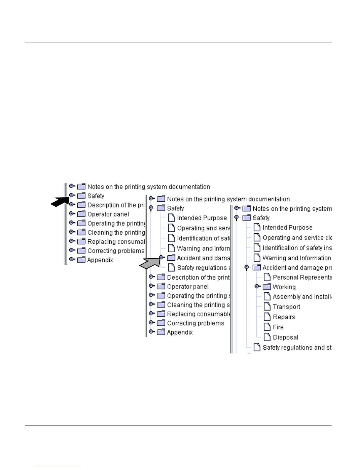
In the "Contents" tab, you can show or hide individual Help levels and select the desired
Help topic, e. g.:
4 A29246-X17-X-4-7680 / all102.fm

1.3.2 Index
1.3.2 Index
The "Index" tab provides quick access to the required information.
You can also search directly for a specific word within index entries.
Proceed as follows:
1. Enter the text into the "Search" input field.
2. Press the Enter key.
Example:
A29246-X17-X-4-7680 / all102.fm 5

1.3.3 Search
1.3.3 Search
You can access the full text search function via the "Search" tab. The full text search is used
to find one or more specific words in the entire Help. Uppercase or lowercase is not relevant
for the search.
Proceed as follows:
1. Enter the text into the "Search" input field.
2. Press the Enter key.
The search results are listed with the title of the corresponding Help topic, and are sorted
by level of matches and the frequency in which the word appears in the Help topic, e. g.:
The circle in the first column indicates the degree of matching. The more filled the circle is,
the better it matches the text that was searched for.
The number in the second column of the search results indicates how often it occurs in the
Help topic.
6 A29246-X17-X-4-7680 / all102.fm

1.3.4 Direct Help
Context-sensitive Direct Help provides detailed information on all:
• Menus
• Operating elements in menus
• Error messages and warnings
If necessary, all setting requirements are also listed in the context-sensitive Help system.
Specified default settings and values are denoted in bold.
Starting direct Help
Proceed as follows:
1. Select menu
1.3.4 Direct Help
or
select operating element
or
select message.
A29246-X17-X-4-7680 / all102.fm 7

1.3.4 Direct Help
Proceed as follows:
2. Press the F1 key.
The Direct Help is opened, e. g.:
8 A29246-X17-X-4-7680 / all102.fm

1.4 Symbols in the text
Different symbols help you to find your way around the text:
Symbols Meaning
<Sample> menu The name of a button or menu on the operator panel is enclosed
SAMPLE button Mechanical buttons are denoted in uppercase letters.
For safety directives, different symbols and alert words are used depending on the degree
of danger:
Caution
Warns against dangers that could lead to injuries.
1.4 Symbols in the text
in angle brackets.
This symbol indicates tips for operating the printing system.
Important
Warns against situations that could lead to damage to the printing system or disruptions to operation.
A29246-X17-X-4-7680 / all102.fm 9

1.5 Symbols in diagrams and illustrations
1.5 Symbols in diagrams and illustrations
If not otherwise indicated, diagrams and illustrations of actions depict the starting position
of the respective component for the described step.
For easier understanding, the diagrams only depict the components that are directly relevant to the immediate context.
Arrows denote the positions where you have to perform an action or observe something in
particular. The color of the arrows denotes the type of actions and the sequence in which
they are performed:
Symbols Meaning
Black arrow: Direction arrow
Perform this action first
Grey arrow: Direction arrow
Perform this action next
2
3
If additional actions are depicted in a diagram, the numbers on the arrows indicate
the sequence in which they are to be carried out, e. g.:
2
3
10 A29246-X17-X-4-7680 / all102.fm

1.5 Symbols in diagrams and illustrations
Symbols Meaning
White arrow: Note arrow
An action should be performed in this area,
e. g.:
A29246-X17-X-4-7680 / all102.fm 11

1.6 Other documents
1.6 Other documents
If not otherwise indicated, the following documents are supplied with each printing system
in addition to the operating manual:
Title Order number
Safety Information on Océ Printing Systems A29246-X23-X-1-79
Papierspezifikation Einzelblatt-Drucksysteme
(Deutsch) and/or
Paper Specification Cut Sheet Printing Systems
(English)
1.7 Manufacturer of the printing system
The printing system was manufactured by:
Océ Printing Systems GmbH
Postfach 1260
85581 Poing
Germany
A29249-X1-X-6-59
A29249-X1-X-6-7659
12 A29246-X17-X-4-7680 / all103.fm

1.8 Statutory requirements
The information, data and instructions in this documentation were up-to-date at the time of
going to press. The right of technical modifications due to further development of the printing system is reserved. For this reason, the information, illustrations and descriptions in this
documentation cannot give rise to any claims for modifications or additions to printing systems that have already been shipped and accepted.
No liability is accepted for damages resulting from:
• Failure to comply with the documentation
• Errors due to improper handling
• Work performed incorrectly on the printing system
• Use of non-original parts and accessories
• Use of non-original consumables
• Unauthorized modification and retrofitting of the printing system by the agent or the
agent’s personnel.
1.8 Statutory requirements
A29246-X17-X-4-7680 / all103.fm 13

1.8 Statutory requirements
14 A29246-X17-X-4-7680 / all103.fm

2 Safety
2.1 Overview
This section gives you all necessary information on how to safely and efficiently operate the
printing system.
You will find information on the following topics:
2.2 Intended Purpose >>> page 16
2.3 Operating and service clearance >>> page 17
2 Safety
2.4 Flagging of safety directives >>> page 18
2.5 Warning and Information signs >>> page 19
2.6 Accident and damage prevention >>> page 21
2.7 Safety regulations and standards >>> page 27
Caution
Please also observe the safety directives in the documentation for any pre-processing
and post-processing devices that may be connected.
A29246-X17-X-4-7680 / all201.fm 15

2.2 Intended Purpose
2.2 Intended Purpose
The printing system shall only be considered as being used for its intended purpose if the
notices and instructions in this documentation are strictly observed.
The printing system is intended solely for printing materials that comply with the paper
specifications (see section 1.6 Other documents, page 12). The printing system may only
be used with the recommended consumables (see section Consumables, page 334) and
under the prescribed operating conditions (see section Technical data, page 337) .
Any use of the printing system that does not comply with the above requirements can cause
damage to the printing system or property and moreover injury to persons.
16 A29246-X17-X-4-7680 / all201.fm

2.3 Operating and service clearance
The operating and service clearance areas for the printing system depicted in the following
diagram should not be obstructed in any way.
For devices with the CustomTone option, additional clearance of 400 mm (15.7") is needed
in front of the printing system to facilitate exchange of the developer station.
For devices with a cascade, the service clearance is extended by approx. 860 mm (33.9")
(the length of the cascade). For devices with an Interposer, the service clearance is
extended by approx. 860 mm (33.9") (the length of the Interposer).
2.3 Operating and service clearance
Dimensions in millimeters (inches)
A29246-X17-X-4-7680 / do202.fm 17

2.4 Flagging of safety directives
2.4 Flagging of safety directives
In addition to the safety directives in section 2.6 Accident and damage prevention, you must
also observe the safety directives outlined elsewhere in this documentation.
The following notational conventions are used for the safety directives in the text of the
manual:
Symbol
Different symbols and alert words are used depending on the degree of danger:
Caution
Warns against dangers that could lead to injuries.
Important
Warns against situations that could lead to damage to the printing system or disruptions to operation.
Example of a safety directive
Important
Fluid can seep inside the machine. This could cause irreparable damage to the electrical and mechanical components.
Do not place cleaning fluids on top of or in the immediate vicinity of the printing system.
Take care to prevent fluids from seeping into the printing system.
Alert word
Type and/or source of danger, and the consequences if the safety guideline is
not observed
Instructions on avoiding danger
18 A29246-X17-X-4-7680 / all203.fm

2.5 Warning and Information signs
The following signs are affixed inside the printing system at potential danger points:
Sign Meaning
Live electric parts
There are live electric parts behind protective covers bearing this sign.
These protective covers may only be removed by authorized Océ service personnel.
Rotating parts!
Parts of the body (particularly fingers), unprotected long hair or loosely
hanging items of clothing and jewelry (e. g. ties, necklaces, belt ends...)
can be crushed, trapped or pulled into the printing system by the rotating mechanism in these areas.
Hot components!
In order to prevent burns, you must observe the cooling periods and
other directives specified in the documentation for all work in these areas.
2.5 Warning and Information signs
Observe documentation
For all work in this area, you must observe the relevant instructions in
the documentation.
The PC drum is light-sensitive
Store the PC drum away from direct exposure to light and sunlight.
Wear gloves
Always wear the provided gloves when working with the photoconductor drum.
(Sheet 1 of 2)
A29246-X17-X-4-7680 / all203.fm 19

2.5 Warning and Information signs
Sign Meaning
Do not touch the photoconductor drum surface.
When working with the photoconductor drum, never touch its surface.
Only grasp the PC drum by the inside.
When working with the photoconductor drum, only hold it on the inside.
Separate Collection
The symbol "the crossed-out wheeled bin" indicates that at the end-oflife of the eqipment separate collection is required in the EU Member
States. The black bar specifies that the appliance is put on the market
after 13 August 2005. Reference: Directive/2002/96/EC.
(Sheet 2 of 2)
20 A29246-X17-X-4-7680 / all203.fm

2.6 Accident and damage prevention
This section contains information on the following topics:
2.6.1 Personal Representations >>> page 21
2.6.2 Operation >>> page 22
2.6.3 Assembly and installation >>> page 25
2.6.4 Transport >>> page 26
2.6.5 Repairs >>> page 26
2.6.6 Fire >>> page 27
2.6.7 Disposal >>> page 27
2.6.1 Personal Representations
2.6 Accident and damage prevention
Agent
An agent is any individual or legal entity (corporate body) that uses or commissions the use
of the printing system.
Operator
An operator is a person who has been instructed or commissioned by the agent to operate
the printing system.
• The requirements for operators are: They are familiar with the contents of the documentation.
• They are aware of the potential dangers of improper handling of the printing system.
• They have been informed about necessary safety installations, safety precautions and
operating conditions.
• They have been instructed or commissioned by the agent to operate the printing system.
Key operator
The Key Operator is an operator to whom the agent has assigned the additional duty of user
management (e. g. allocation of user rights and passwords). The Key Operator can also
display or hide menus for the different operators and accordingly adapt the menu structure
to the respective requirements.
A29246-X17-X-4-7680 / all203.fm 21

2.6.2 Operation
Service
Service staff are specialized Océ personnel who carry out all work that operators do not
have the permission to, on and with the printing system. (e. g., any work on the power circuits in the printing system).
2.6.2 Operation
Observe the following instructions when using the printing system:
2.6.2.1 Operator >>> page 22
2.6.2.2 Safety covers >>> page 23
2.6.2.3 Assemblies >>> page 23
2.6.2.4 Cleaning >>> page 24
2.6.2.5 Foreign bodies, noises >>> page 24
2.6.2.6 Cooling, heat >>> page 24
2.6.2.7 Consumables and expendables >>> page 25
2.6.2.8 Optical wave guide >>> page 25
2.6.2.9 Laser >>> page 25
2.6.2.10 Remote control via LAN >>> page 25
2.6.2.1 Operator
• Only operators, key operators and service personnel may use the printing system.
• The printing system must not be operated by persons under the influence of alcohol or
drugs, or by persons taking medication such as psychotropic drugs.
• Before operating the printing system, carefully read through the documentation. If you do
not understand something in the documentation, please ask (e.g. ask service).
• Observe all warning and information signs both on and in the printing system (see section
2.5 Warning and Information signs, page 19).
• In case of emergency, immediately turn off the printing system (location of the main circuit
breaker see section 3.2.3 Internal view, page 33). In the event of damage to the housing,
power cable or operating controls, or penetration of fluids or foreign bodies, call the appropriate service representative.
22 A29246-X17-X-4-7680 / all203.fm

• Do not work with unprotected long hair or wear loosely hanging items of clothing (e. g.
ties, sleeves, scarves et. c.), or jewelry such as necklaces, bracelets and rings. since
these can cause injury if caught in drive mechanisms.
2.6.2.2 Safety covers
• Do not attempt to remove safety covers yourself; do not manipulate safety equipment
such as the switches monitoring the safety covers, and do not perform any work not intended to be performed by operators. Such action can cause accidents and may also
damage the printing system.
• Safe operation of the printing system is guaranteed only when the outer paneling is fully
mounted. Only if the paneling is affixed correctly and completely are you assured protection against:
– Electrical shocks
– Injury from mechanical parts, e. g. cuts, drawing in, crushing
– The spread of fire
2.6.2.2 Safety covers
– Insufficient cooling of the printing system
• Keep all doors, trims, flaps and covers closed while the printing system is in operation.
This ensures that limit values for radio interference suppression are not exceeded. The
noise emission is also minimized.
2.6.2.3 Assemblies
When Removing
• the Developer Station
• the Fuser Station
• the Transfer Station
• the Cleaning Station
• the Input Trays
• the Output Trays
always slide slowly and evenly to its stop point on the guide rail (reference speed max. 0,5
m/s).
A29246-X17-X-4-7680 / all203.fm 23

2.6.2.4 Cleaning
2.6.2.4 Cleaning
• Observe the instructions in section 6 Cleaning the printing system for cleaning the printing
system.
• For vacuuming, an industrial vacuum cleaner with grounded suction device, rubber nozzle and a filter insert for fine dustshould be used. When vacuuming large quantities of toner spill (e. g. 1 bottle), an explosion-proof industrial vacuum cleaner must be used because there can be a high build-up of static charge when draining toner spill.
• Only use the recommended cleaning agents and equipment (see section Cleaning
agents and equipment, page 336).
2.6.2.5 Foreign bodies, noises
• Make sure that no objects (e. g. jewelry chains, paper clips, coins etc.) or liquids get into
the interior of the printing system, since this may result in electric shocks or short circuits.
Do not place objects on the printing system, and especially do not place containers with
fluid, such as drinking bottles, glasses, cups or vases on top of or in the immediate vicinity
of the printing system.
• Should the printing system emit any unusual or noticeable noises or smells, power down
the printing system and contact your service engineer.
2.6.2.6 Cooling, heat
• Do not obstruct the cooling ducts, since this may result in overheating or combustion
while the device is in operation.
• Make sure there is an adequate supply of fresh air and cooling air to the room in which
the printing system is located (see section Technical data, page 337).
• Do not obstruct the operating and service clearance areas in any way (see section 2.3
Operating and service clearance, page 17) .
• During operation, the fusing station in the printing system becomes very hot (up to
approx. 230° C / 446° F).
/ 446° F)You should therefore maintain the cooling times before beginning work in the
the Fuser Station area, and observe the corresponding instructions in this documentation
to avoid burns.
24 A29246-X17-X-4-7680 / all203.fm

2.6.2.7 Consumables and expendables
• Observe the safety directives given in the manual for:
– Toner
– Developer
– Fine filter
– Fuser oil
– Photoconductor drum
– Cleaning agents
• Keep all consumables for the printing system out of the reach of children. Store consumables away from containers used for food and drink.
2.6.2.8 Optical wave guide
• If the printing system has a connection for optical wave guides:
Never look directly into a glass fiber cable or glass fiber cable connection. The laser
beams in fiber optic devices can injure your eyes.
2.6.2.7 Consumables and expendables
2.6.2.9 Laser
• If the printing system contains a laser:
Never look directly into a laser beam or laser optics. Never move a tool near the laser
beam so that you do not unintentionally divert the laser beam.
The laser beams in fiber optic devices can injure your eyes.
2.6.2.10 Remote control via LAN
• If you operate the printing system from a remote operator panel:
The access ticket ensures that only one user at a time can access the printing system.
(see section 4.3.2.1 Log on as user and request an access ticket, page 70).
2.6.3 Assembly and installation
Observe the following instructions when assembling and installing the printing system:
• The printing system may only be assembled and installed by service personnel.
• The printing system must have a dedicated electrical connection or type B plug connection (complying with VDE directives, EN 60950).
A29246-X17-X-4-7680 / all203.fm 25

2.6.4 Transport
• Do not route the lines and cables in such a way that they can be trodden on or tripped
• A ventilating flue without a smoke detector should be installed above the fuser module.
• All printing system accessories and options must comply with statutory regulations and
• The installation of other accessories may constitute a violation of these requirements and
• Consult service personnel for details on which accessories and options are permitted for
over.
In very rare cases, paper jammed in the fuser module could be damaged by the infrared
fuser to the extent that smoke escapes. However, even in this case there isno danger of
fire because the affected component is immediately isolated by seal bulkheads from the
remaining print system. This bulkhead shielding is part of a tested security concept and
does not effect the availability of the print system after the jammed paper has been removed.
directives for safety, radio interference suppression, telecommunications terminal devices, as well as with the specifications published by Océ Printing Systems GmbH. Océ
Printing Systems GmbH.
directives, and may also damage the printing system.
the printing system.
• With the exception of optical wave guide connections, all data, signaling, process and
control lines and holding wires mapping the printing system with other devices must be
properly grounded.
• Data transmission lines should neither be connected nor disconnected during electrical
storms.
2.6.4 Transport
The printing system may only be transported by service personnel or authorized transport
companies.
2.6.5 Repairs
Repairs to the device must only be carried out by service personnel. Access to locked areas
and areas which can only be opened with special tools is reserved for service personnel.
Opening the device without authorization and improperly effected repairs may put operators
at considerable risk.
The access ticket used by the service technician ensures that the printing system cannot
be used via a LAN from a remote operator panel during repair work.
26 A29246-X17-X-4-7680 / all203.fm

2.6.6 Fire
Observe the following instructions:
• Fire in the printing system can cause toxic gaseous emissions.
• Selfcontained breathing apparatus must be worn when fighting the fire. Instructions to this
effect should be deposited at the fire alarm center and with the local fire-fighting force.
• Fire can cause toxic arsenic gas to develop on the photoconductor drum.
• These security measures apply particularly in case of fire in locations where a number of
photoconductor drums are stored.
2.6.7 Disposal
Océ operates a system by which used parts and consumables can be returned for environmentally sound disposal.
• Collect all parts and consumables that are to be returned for disposal. These will be
picked up by Océ Printing Systems GmbH or a commissioned shipping company or a
contracted disposal company and then recycled or disposed of appropriately.
2.6.6 Fire
• When disposing of a photoconductor drum, please observe the following:
– Before touching the drum, always put on the gloves provided with the drum.
– Should there be flaking of the photosensitive coating on the drum, carefully collect the
flakes or fragments of the coating.
– Store the photoconductor drum and any flakes of coating in the original drum packag-
ing.
– The drums and coating are hazardous waste and require special disposal. They should
be disposed of by Service or a Contracted Shipping Company. Keep this carton and its
contents out of the reach of children.
– Wash your hands afterwards.
2.7 Safety regulations and standards
The printing system complies with the relevant safety requirements for information technology equipment. It meets the following national and international product standards and regulations:
• VDE 0805/11.93 / VDE-GS-mark
A29246-X17-X-4-7680 / all203.fm 27

2.7 Safety regulations and standards
• TRGS 402/ TRGS 100
• IEC 60950
• EN 60950
• UL 60950
• CSA Standard C22.2 No. 60950
• EN 55022 / class A (Europe)
• EN 55024
• FCC Part 15 Subpart B Class A (USA)
• C108.8 (Canada) M1983 Class A (Canada)
CE Mark
The printing system fulfills the requirements of the EC directives 89/336/EWG, "Electromagnetic Compatibility" and 73/23/EWG "Low Voltage Directive".
The CE Mark indicates that the printing system complies with these EC directives.
All other devices that are attached to the printing system must also comply with the requirements set forth in the relevant EC directives.
The printing system is a Class A product (EN 55022). This product may cause radio interference in a domestic environment. In this case, the agent may be required to take appropriate measures to correct the interference at his or her own expense.
28 A29246-X17-X-4-7680 / all203.fm

3 Description of the printing system
3 Description of the printing system
3.1 Overview
This section describes the structure of the VarioPrint 5000 and VarioPrint 5000 advanced
printing systems without additional elements and by use of diagrams. It contains a short
overview of the operating controls and gives a summary of the different paper paths for
different print modes (e.g. simplex printing, duplex printing, etc.).
You will find information on the following topics:
3.2 Device overview >>> page 30
3.3 Operating elements >>> page 36
3.4 Paper path >>> page 39
3.5 Interposer >>> page 45
A29246-X17-X-4-7680 / do301.fm 29

3.2 Device overview
3.2 Device overview
This section contains information on the following topics:
3.2.1 Front view >>> page 31
3.2.3 Internal view >>> page 33
3.2.4 Rear view >>> page 34
30 A29246-X17-X-4-7680 / do301.fm

3.2.1 Front view
3.2.1 Front view
17
123 4 7 8 9 10
5 6
15
141516
11
12
13
1 Output tray A
2 Output tray B
3 Sample tray
4 Flap of upper toner supply canister
5 On key for printing system
6 Keyboard with mouse
7 Control panel
8 Slide of lower toner supply canister
9 Operator panel for input trays
10 Input tray 4
11 Input tray 3
12 Input tray 2
13 Input tray 1
14 Right door
15 Center doors
16 Left door
17 Keys for output trays
A29246-X17-X-4-7680 / do301.fm 31
3.2.2 Front view of VP5000 advanced
3.2.2 Front view of VP5000 advanced
18
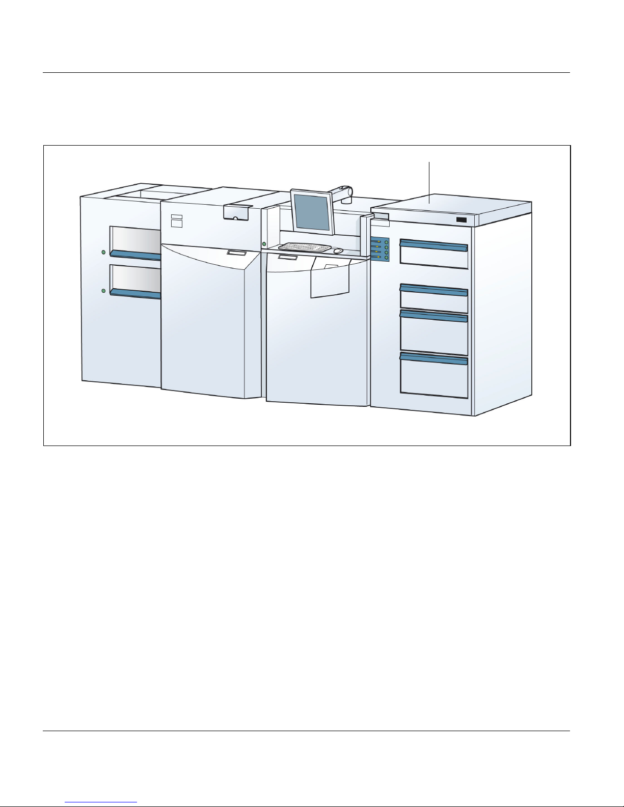
18 Housing with server
32 A29246-X17-X-4-7680 / do301.fm

3.2.3 Internal view
3.2.3 Internal view
123 54
1 Fuser station
2 Fuser oil container
3 Cleaning station
4 Charge station
5 Toner supply canister
6 Reject tray
7 Main power switch
8 Lower print unit
9 Upper print unit
10 Developer station
11 PC drum
12 Transfer station
9
101112
8
7 6
A29246-X17-X-4-7680 / do301.fm 33

3.2.4 Rear view
3.2.4 Rear view
1
2
3
4
1 Fine filter of upper print unit
2 Rear waste toner collector of upper print unit
3 Fine filter of lower print unit
4 Rear waste toner collector of lower print unit
34 A29246-X17-X-4-7680 / do301.fm

3.2.5 Rear view of VP5000 advanced
5
3.2.5 Rear view of VP5000 advanced
5 Housing with server
A29246-X17-X-4-7680 / do301.fm 35
3.3 Operating elements
3.3 Operating elements
Different types of operating controls are available for the printing system:
3.3.1 Operating controls on the front of the housing >>> page 36
3.3.2 Operating controls in the printing system >>> page 38
3.3.1 Operating controls on the front of the housing
Position Operating control and function
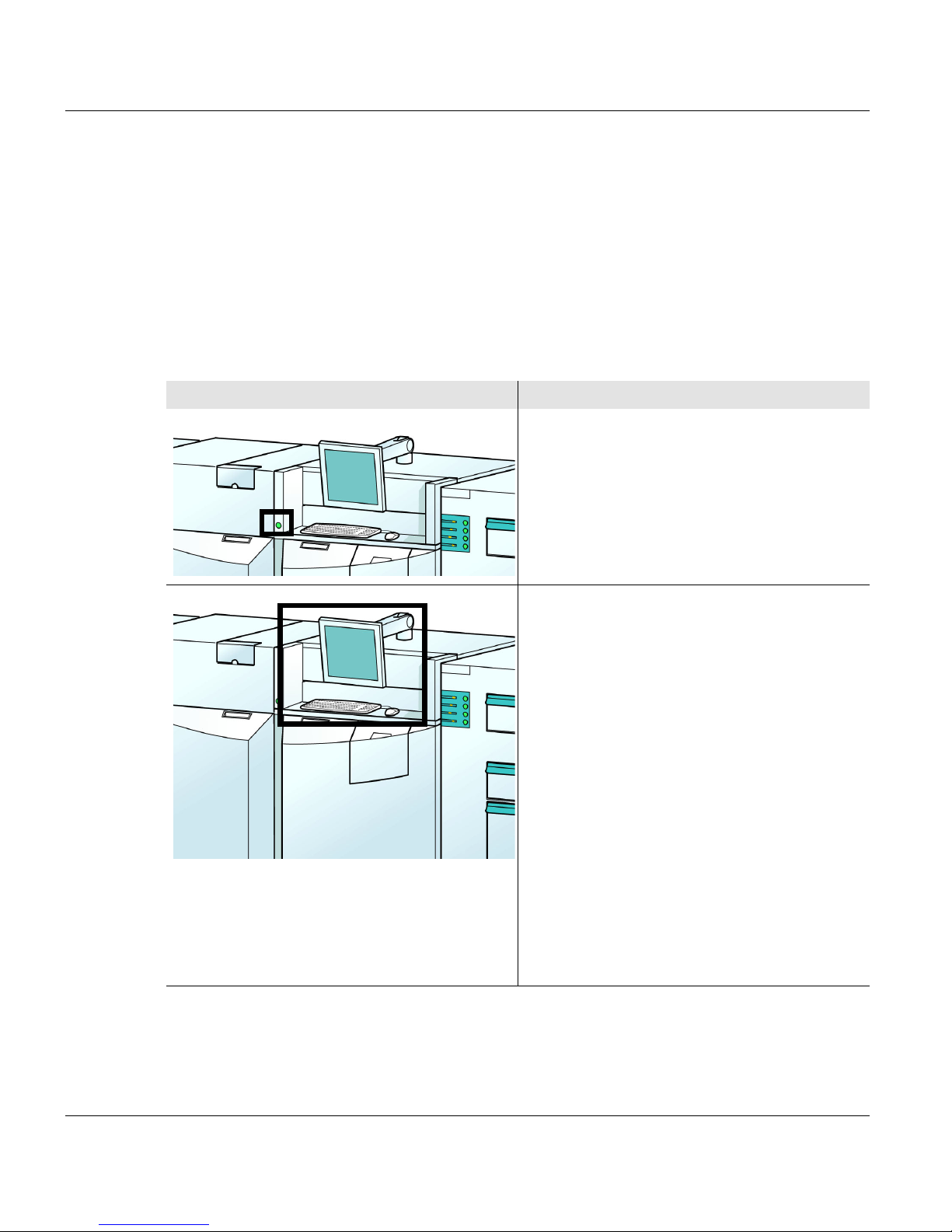
On key
After switching on the main power switch,
start the printing system’s start-up
procedure with the On key.
See 3.2.1 Front view >>> page 31 for the
position of the main power switch
Operator panel with monitor, keyboard, and
mouse
At the operator panel, the settings for the
printing system are selected, the printer
status is queried and information for the
operator is available. Use both the mouse
and the keyboard to do things like enter
alphanumerical values.
The monitor can be swiveled vertically and
horizontally in order to bring it into the most
convenient position.
Use the operator panel to turn off the
printer.
Detailed descriptionsee section 4 Operator
panel, page 47
36 A29246-X17-X-4-7680 / do301.fm

3.3.1 Operating controls on the front of the housing
Position Operating control and function
Operator panel for input trays
It consists of a key and a row of display
lamps for each input tray.
• Keys for each input tray:
– The selected input tray is lowered when
the key is first pressed
– The selected input tray is ejected when
the key is pressed again
• Row of display lamps for each input tray.
It indicates
– the filling level of the selected input tray
by lighting the appropriate number of
display lamps
– the downward movement of the input
tray by flashing all display lamps
– that the input tray has reached the
lower position by continuously lighting
up all lamps
– that the paper format setting in the
menu does not match the mechanical
setting in the input tray by rapid flashing
– that a sheet is being fed into the paper
path by flashing the right display lamp
Keys for output trays
There is one key for each output tray. The
key is pressed to lower the stacker platform
in the corresponding output tray before the
paper is removed.
A29246-X17-X-4-7680 / do301.fm 37

3.3.2 Operating controls in the printing system
3.3.2 Operating controls in the printing system
All operating controls, such as buttons, handles, slides etc. which the operator may use in
the printing system are green. These include:
• green knobs and release knobs: Operating controls for removing a paper jam
• green knobs to release and pull out the stations, for example at the transfer station
• green handles to pull out the stations, for example at the developer station
• green handles on the levers to set the paper width and length in the input trays
38 A29246-X17-X-4-7680 / do301.fm

3.4 Paper path
This section describes the paper path for the following print modes:
3.4.1 Simplex printing >>> page 39
3.4.2 Duplex printing >>> page 40
3.4.3 Simplex printing with two colors >>> page 41
3.4.4 Duplex printing with two colors >>> page 42
3.4.1 Simplex printing
In simplex printing (auto mode), the paper is fed alternately to the upper and lower print
units and printed on one side.
After printing, the papers are merged and then conveyed to the paper output unit.
3.4 Paper path
-xo-:Path taken by paper in input unit before printing
-x-: Path taken by paper in lower paper path before printing
-o-: Path taken by paper in upper paper path before printing
-xx-: Path taken by paper in lower paper path after printing
-oo-: Path taken by paper in upper paper path after printing
-ooxx-: Path taken by printed and merged paper
A29246-X17-X-4-7680 / do301.fm 39

3.4.2 Duplex printing
3.4.2 Duplex printing
In duplex printing (auto mode), the paper is printed on both sides. It is conveyed from the
input to the lower print unit and then up via turning bay 1. There it runs through the upper
print unit and is transported to the paper output via turning bay 2.
Turning bay 2:
Turning bay 1:
-o-: Path taken by paper before printing
-oo-: Path taken by paper printed on one side after printing
-ooo-: Path taken by paper printed on both sides after printing
Turning bay 1::Duplex turning bay
Turning bay 2: Face down turning bay
40 A29246-X17-X-4-7680 / do301.fm

3.4.3 Simplex printing with two colors
In two-color simplex printing (CustomTone simplex), the same side of the page is printed in
two different colors. Each print unit prints part of the print image in a different color.
The paper is fed from the input to the lower print unit and the first part of the image is then
printed. The paper then travels up directly to the upper print unit, which prints the second
color. The paper is then conveyed to the paper output.
3.4.3 Simplex printing with two colors
-x-: Path taken by paper before printing
-xx-: Path taken by paper after printing of first part of image in first color
-xxx-: Path taken by paper printed on both sides after printing
2
A29246-X17-X-4-7680 / do301.fm 41

3.4.4 Duplex printing with two colors
3.4.4 Duplex printing with two colors
In two-color duplex printing (CustomTone duplex), each side of the page is printed in two
colors.
3.4.4.1 Printing on the front side with two colors
The paper is fed from the input to the lower print unit and the first part of the image is printed
on the front side. The paper then travels up to the upper print unit, where the second color
is added to the front side, and then on to turning bay 3.
Turning bay 3:
-o-: Path taken by paper before printing
-x-: Path taken by paper after printing of first part of image on front side
-xx-: Path taken by paper after both colors are printed on front side
Turning bay 3: Duplex turning bay color printing
: End of stage 1
42 A29246-X17-X-4-7680 / do301.fm

3.4.4.2 Printing on the back side with the first color
3.4.4.2 Printing on the back side with the first color
The paper printed on one side, now changes direction in turning bay 3 and travels
diagonally to the upper paper path. It is then conveyed back to the lower print unit, which
prints the first part of the print image on the back side.
Turning bay 3:
: Start of stage 2
-xx-: Path taken by paper after both colors have been printed on front side
-xxx-: Path taken by paper after printing of first part of image on back side
Turning bay 3: Duplex turning bay color printing
: End of stage 2
A29246-X17-X-4-7680 / do301.fm 43

3.4.4.3 Printing on the back side with the second color
3.4.4.3 Printing on the back side with the second color
After leaving the lower print unit, the paper is conveyed directly to the upper print unit which
adds the second color to the print image on the back side. The paper is then conveyed via
turning bay 2 to the paper output.
Turning bay 2:
: Start of stage 3
-xxx-: Path taken by paper after printing of first part of image on back side
-xxxx-: Path taken by paper after both colors are printed on back side
Turning bay 2: Face down turning bay
44 A29246-X17-X-4-7680 / do301.fm

3.5 Interposer
The Interposer is a paper input unit that is used for paper post processing devices, which
can integrate additional paper that cannot be printed on into customer applications. For
example, it enables you to automatically insert pre-printed cover sheets, tabs as well as fine
paper that should not go through the printing system’s fusing process into customer jobs.
The Interposer is positioned right after the paper output of the printing system and before
the paper post processing device. It has four input trays for a total of 5200 A4 pages with
80 g/m². Its setup and operation is similar to the paper input of the printing system and
cascade. The range of paper that can be used is identical to the pneumatic paper input (see
section Technical data, page 337).
Paper from the Interposer is no longer printed, but rather it is sent directly from the
Interposer to the next paper post processing device. The paper is then inserted in the stack
as defined in the print job.
Cleaning, maintenance and error handling, e.g. paper jam is carried in a similar fashion as
with the paper input and the cascade.
3.5 Interposer
6.4.1 Cleaning the input trays >>> page 181
8.3.2.4 Clearing a paper jam in the paper input, cascade or Interposer >>> page 298
Note on using tabs
Only one tab set can be used in the entire printing system. This means that the tab
set can only be inserted in the paper input or in the Interposer. A combination of this
type is not possible.
Tabs with Euro perforation should not be used.
Note regarding transparent media
Transparent media cannot be used.
A29246-X17-X-4-7680 / do301.fm 45

3.5 Interposer
46 A29246-X17-X-4-7680 / do301.fm

4 Operator panel
4.1 Overview
This section describes the individual areas of the operator panel with the most important
symbols and buttons (Version 02.05.27). You will also find out how to navigate through the
menus, set parameters and to start and acknowledge the replacement of consumables and
expendables.
You will find information on the following topics:
4 Operator panel
4.2 Operator panel description >>> page 48
4.3 Using the operator panel >>> page 65
Note
Detailed information on all the menus and control elements is available directly on
the operator panel via the context-sensitive Direct Help system. The contextsensitive help system can be called up by selecting the relevant menu or control
element and then pressing the F1 key.
If required, the direct help also lists all prerequisites for setting the respective
parameter . Specified standard settings and values are denoted in bold.
A29246-X17-X-4-7680 / do401.fm 47

4.2 Operator panel description
4.2 Operator panel description
The operator panel is divided into three main areas. Click on the operating controls with the
mouse; enter alphanumerical values with the keyboard.
1
2
1 Toolbar: see section 4.2.1 Toolbar of VarioPrint, page 49
2 Menu tree: see section 4.2.2 Menu tree, page 56
3 Menu display: see section 4.2.3 Menu display, page 63
3
48 A29246-X17-X-4-7680 / do401.fm

4.2.1 Toolbar of VarioPrint
The toolbar can be used to access important functions of the printing system quickly and to
switch directly to frequently used menus.
4.2.1 Toolbar of VarioPrint
1
2
3
1 see section 4.2.1.1 Buttons and displays in the left-hand area, page 50
2 see section 4.2.1.2 Center area buttons and displays, page 51
3 see section 4.2.1.3 Frame icon bar, page 55
A29246-X17-X-4-7680 / do401.fm 49
4.2.1.1 Buttons and displays in the left-hand area
4.2.1.1 Buttons and displays in the left-hand area
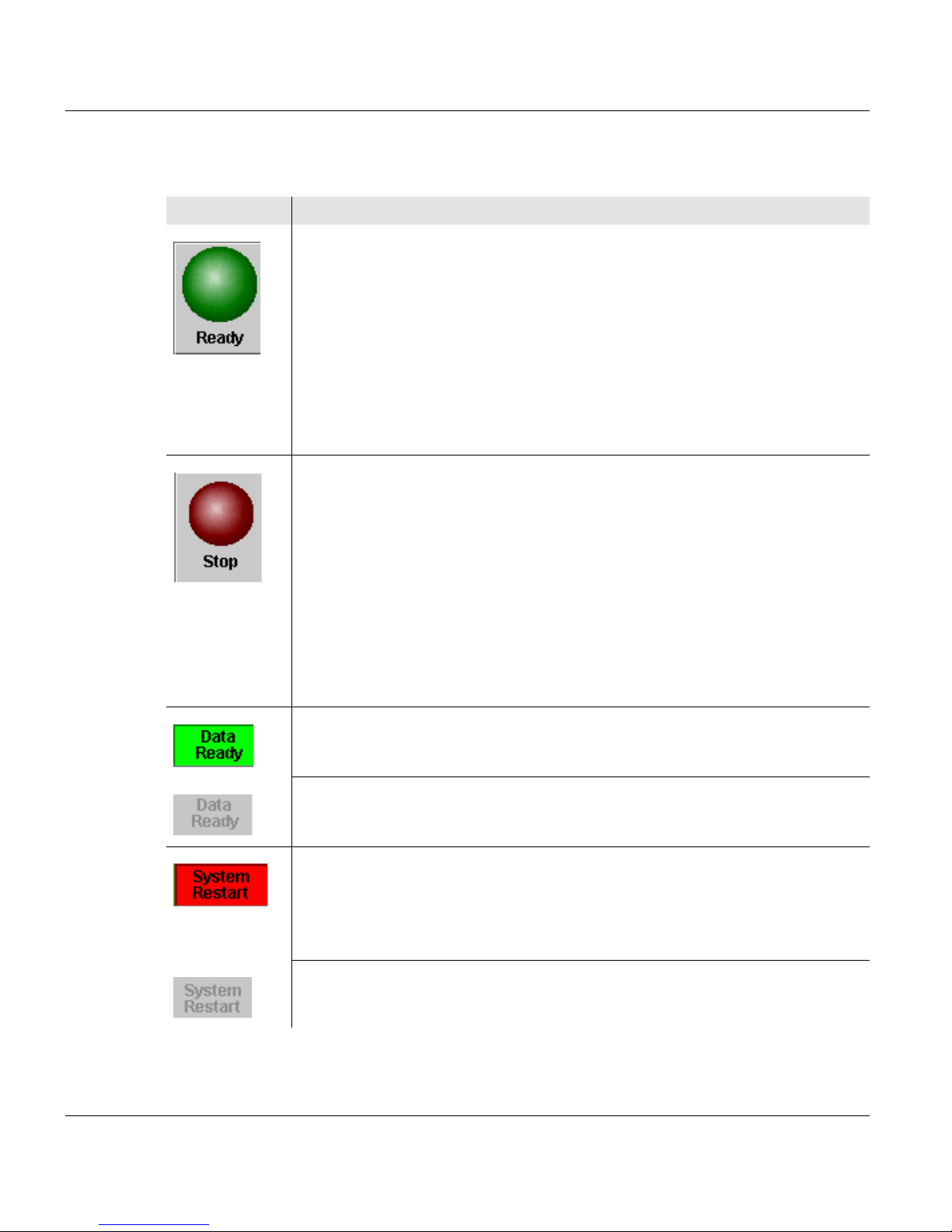
Button Function
switches the printing system back from "Stop" or "Error" status to
operational status.
Requirements:
• all errors corrected
• Controller and system control are ready
When the printing system is ready for operation:
• printing is continued, when data is present
• "Ready" is displayed in the status display
• the color of the button changes from dark green to light green
the printing system switches to the "Stop" status.
Before the printing system stops, the pages produced on the PC drum
are transferred to the paper. All printed pages in the paper path are
ejected to the selected output tray.
With this button, an error can also be reset after correction without
changing the printing system status to "Ready". This means that paper
can be added or another activity can be carried out before printing is
continued.
In the "Stop" mode, the color of the button changes from dark red to pale
red.
Indicates that print data has been transferred from the host.
Standard display (no current print data from the host).
Indicates that the controller is performing a restart.
If this message is displayed, the host has to repeat the print data transfer
since it cannot be guaranteed that the last pages were correctly
transferred and fused before the error occurred.
Standard display (no controller restart).
50 A29246-X17-X-4-7680 / do401.fm
4.2.1.2 Center area buttons and displays
Button / Display Function
4.2.1.2 Center area buttons and displays
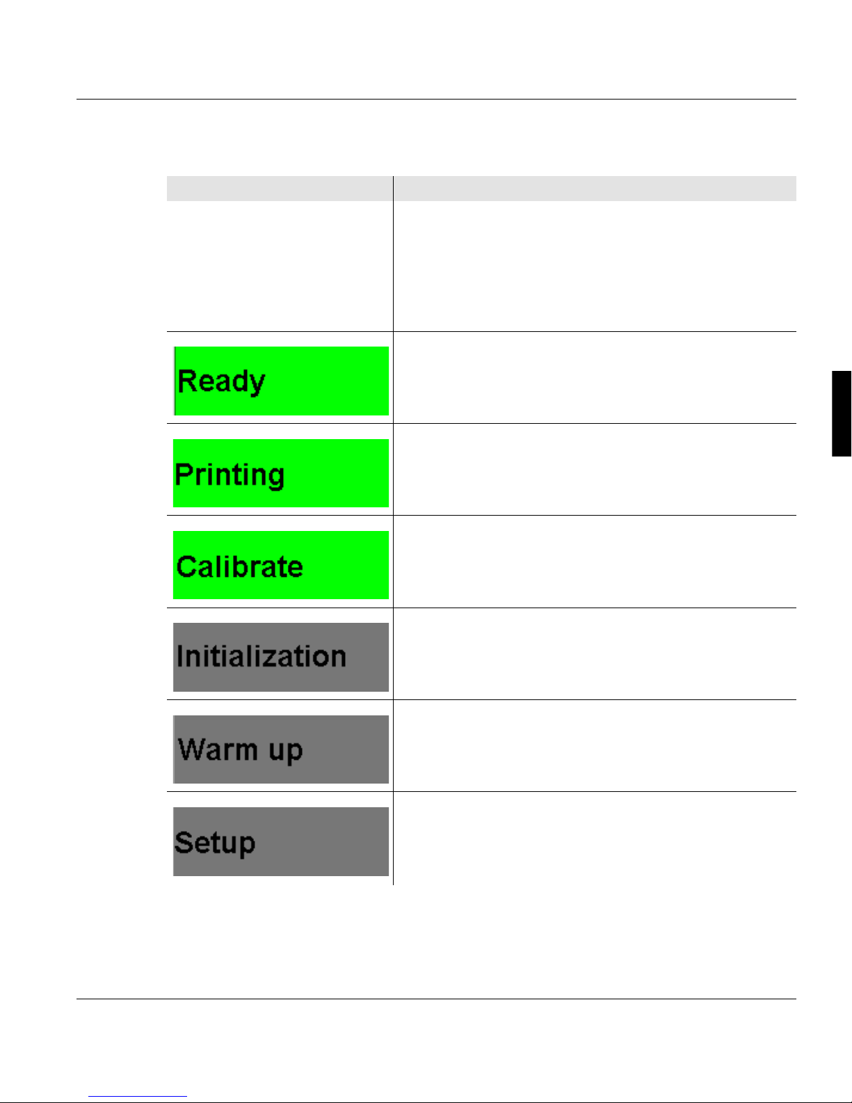
Displays the current printer status.
The individual displays have different background colors
depending on the printer status:
• Green: the printer is printing or is ready to print
• Red: error
• Gray: all other printer states
The printing system is ready to print, there are no error
messages.
Normal print operation.
An internal setup is being carried out.
The printing system is being initialized and is not yet
ready for printing.
The fuser station is warming up.
A setup is being loaded or saved.
A29246-X17-X-4-7680 / do401.fm 51

4.2.1.2 Center area buttons and displays
Button / Display Function
The printing system is switching to "Stop" status.
Printing is interrupted because pre/post processing has stopped. The printing process
continues when the pre/post processing is ready.
The printing system is in "Stop" status.
The printing system is being prepared for power off. The
shut-down setup is being written, all components are
being exited.
Error message. The error must be remedied, otherwise
printing cannot continue.
If available, the message with the highest priority is
displayed underneath the status display.
All current error messages as well as all warning
messages and information are displayed in the <Errors
and Warnings> menu.
As soon as an MICR toner is in the printing system, this
display will appear next to the status display.
52 A29246-X17-X-4-7680 / do401.fm
Button / Display Function
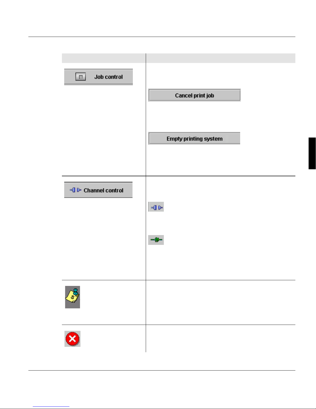
changes to the <Emulations> menu. Here the following
buttons are available under "Job control":
Cancels the current print job.
The data in the page buffer is erased.
Requirement: The printing system is in "Stop" status.
only in PCL mode and only if the printing system is in the
"Stop" state:
Cancels the current print job. The data in the page buffer
is still being printed out.
4.2.1.2 Center area buttons and displays
changes to the <Channels> menu. Here the following
buttons are available:
Activates the channel.
The clutch icon is closed.
Deactivates the channel.
The clutch icon is opened.
During the time needed for activation/deactivation of a
channel, the clutch icon is shown in yellow.
If a message was also transmitted by the data stream,
this icon is displayed:
Clicking on the icon will take you directly to "Job
Preparation" tab in the menu.<Setup> The complete
message will be displayed there.
Flashes when there is an error message.
A29246-X17-X-4-7680 / do401.fm 53
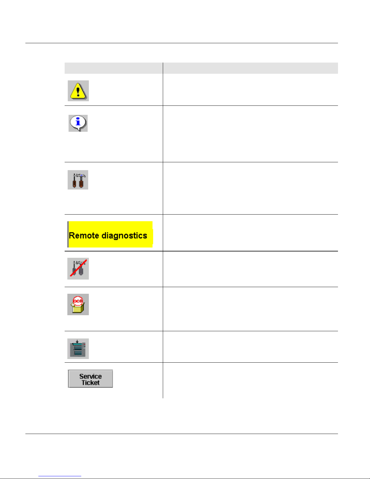
4.2.1.2 Center area buttons and displays
Button / Display Function
Flashes when there is a warning.
Flashes when there is information.
When there is no error message, warning or information,
the button is hidden.
Clicking on the button, takes you to the menu <Errors
and warnings> .
Indicates that remote access is activated. The service
center can use this to perform a remote diagnosis during
printer operation.
Clicking the button deactivates remote access directly
without having to go through the menu.
Also indicates that remote access is activated.
Indicates that remote access is not activated.
Clicking the button activates remote access directly
without having to go through the menu.
changes to the Menu <Consumables counter>.
This menu displays the current counter values and the
respective limit values for all consumables and
expendables in the printing system.
Prints a sample page according to the settings in the
corresponding menu.
Switches to the menu<Service ticket>.
This menu displays all the data required to notify the
relevant service center.
54 A29246-X17-X-4-7680 / do401.fm

4.2.1.3 Frame icon bar
On the right is the higher-level frame icon bar for the complete printing system. These
buttons can be used to quickly access higher-level functions in the printing system, and to
switch directly to frequently used menus.
Button Function
4.2.1.3 Frame icon bar
Switches to the <User profile> menu.
The language of the operator panel can be changed in this menu.
Indicates that the presently logged-on user possesses the access ticket.
Clicking releases the access ticket directly without going through the
menu.
Indicates that the access ticket is released for other other users.
Clicking requests the access ticket directly without going through the
menu.
opens Help.
Switches to the <Change user> menu.
Users can be registered or canceled in this menu.
Displays the user currently logged on.
Turns off the entire printing system when the query is confirmed.
changes from any submenu directly to the main menu of the printing
system or the UP3I manager.
A29246-X17-X-4-7680 / do401.fm 55

4.2.2 Menu tree
4.2.2 Menu tree
All the menus can be accessed via the menu tree.
The menus are structured into main groups, e. g:
• [0] <General>
The user settings valid for the entire printing system can be made in these menus.
• [1]<VarioPrint>
These menus are used to set the relevant parameters for the "VarioPrint" printing system.
• Any additional devices, e. g. paper post processing equipment
The numbers before the main groups are required to identify the devices in the printing
system.
With the mouse, clicking in the menu tree lets you show or hide other menu levels, e. g.:
You can toggle directly to the main menu from any menu. Click the following button in the
icon bar for this purpose:
56 A29246-X17-X-4-7680 / do401.fm

Note
The menus displayed in the menu tree depend on the different authorizations for the
individual user categories.
This documentation describes all menu options normally set up for the user
categories "Operator" and "Key Operator".
Further information:
4.2.2.1 Menus <General> >>> page 57
4.2.2.2 Menus <VarioPrint> >>> page 58
4.2.2.3 Menus <Paper Path Manager> >>> page 62
4.2.2.1 Menus <General>
In the <General> menu, you can make user settings for the entire printing system.
4.2.2.1 Menus <General>
You will find information on the following topics:
4.3.1 User settings by the Key Operator >>> page 66
4.3.2 User settings made by the Operator >>> page 69
Note
You will find information on the <General> menu in Help in the printing system operator
panel.
A29246-X17-X-4-7680 / do401.fm 57

4.2.2.2 Menus <VarioPrint>
4.2.2.2 Menus <VarioPrint>
Note
Menus that can be opened by the user "Key operator" as standard are shown in
italics in the table.
Menu Description
Menus <VarioPrint> Display of basic information on the printing
system:
• Number of all DIN A4 pages printed in the user
operation so far
• Setup currently loaded
• Available emulations
• Name of the printing system
• Current print job
In addition, the printing system display indicates
when current error messages, warning
messages or information messages are present.
The sub-menus contain all settings and displays
relating to the "VarioPrint" printing system
Menus <Displays> The lower level menus contain displays on
current error and warning messages and the
different counters on the printing system
Menu <Errors and warnings> Displays the current error and warning
messages and information
Menu <General counters> Display of general and format-dependent
counters as well as the power-on, print and
standby times
Menu <Consumables counter> Displays the current counter values and the
relevant limit values for all consumables and
expendables of the printing system
Menu <Consumables history> Displays all replacement actions for all replaced
consumables/expendables with time and
counter count
Menus <Configuration> The lower level menus contain the parameters
for setting the printing system
Menus <Paper> The lower level menus contain the parameters
for the papers to be printed
58 A29246-X17-X-4-7680 / do401.fm

4.2.2.2 Menus <VarioPrint>
Menu Description
Menu <Format preselection> Selection of formats displayed in the paper
menus:
• <Paper> <Format sizes> <Format selection>
• <Paper> <Papers> <Standard properties>
Menu <Format sizes> Selection or input of formats and setting of format
attributes
Menu <Paper preselection> Selection of papers displayed in the paper and
input menus
Menu <Papers> Selection or input of papers and setting of paper
attributes and shifts
Menu <Global shift> Setting the global shift.
Menus <Input> The lower level menus contain the parameters
for the paper input trays
Menu <General> Setting of general parameters for the paper input
Menu <Tray assignment> Assignment of papers to individual input trays
Menu <Logical trays> Display of the papers assigned to the various
physical input trays
Menu <Tray attributes> Display and setting of attributes of the individual
input trays
Menu <Tray priorities> Display and setting of the priorities of the
individual input trays
Menu <Links> Display and settings of the mappings between
tray numbers, paper names and input trays used
Menus <Output> The lower level menus contain the parameters
for the paper output trays
Menu <General> Setting of general parameters for the paper
output trays
Menu <Tray attributes> Display and setting of attributes of the individual
output trays
Menu <Tray priorities> Display and setting of the priorities of the
individual output trays
A29246-X17-X-4-7680 / do401.fm 59

4.2.2.2 Menus <VarioPrint>
Menu Description
Menu <Links> Display and settings of the mappings between
Menus <Print parameters> The lower level menus contain specific
Menu <Contrast> Setting the contrast for the upper and lower print
Menu <Fusing temperature> Setting the fusing temperature for the upper and
Menu <Oiling> Setting the oiling temperature for the upper and
Menu <Print mode> Setting of print mode and output direction
Menu <Color management> Settings for the colors in the upper and lower
tray numbers, paper names and output trays
used
parameters for the printing system
units
lower print units
lower print units
print units
Menu <Emulations> Display of emulations, buttons for job control and
for restarting
Menu <General> Selection of the functional code version
Menus <I-mode> The sub-menus contain the parameters for I
mode
Menu <Properties> Settings for font capture, data resolution and
logical page add-on
Menu <Cut sheet> Selection of the standard paper size
Menu <Standard resources> Selection and input of standard resources for I
mode
Menu <Resource management> Installing new resources or
deleting existing resources
Menus <PCL mode> The sub-menus contain the parameters for PCL
mode
Menu <Properties> Settings for job separation, alignment, print
mode, number of copies and lines per forms
overlay
Menu <Cut sheet> Selection of the standard paper size
60 A29246-X17-X-4-7680 / do401.fm

4.2.2.2 Menus <VarioPrint>
Menu Description
Menu <Standard resources> Selection and input of standard resources for
PCL mode
Menu <Resource management> Installing new resources or
deleting existing resources
Menu <Channels> Display of current channel settings and settings
for the channel control.
Menu <Channel A> Selection and input of the parameters for
Channel A
Menu <Channel B> Selection and input of the parameters for
Channel B
Menu <Channel C> Selection and input of the parameters for
Channel C
Menus <Special functions> The lower level menus contain special
parameters for the printing system.
Menu <Printing system> Settings for cleaning pages, double page sensor,
and auto restart
Menu <Park corotrons> Procedure for Parking the corotrons if they need
to be replaced or if the paper path needs to be
cleaned.
Menu <Operator trace> Writing an error log
Menu <Service ticket> Display of all data required to notify the service
center
Menu <Remote diagnostics> Activating or deactivating remote access by the
service
Menu <Sample page> Printing of a sample page according to the
settings in the Menu <Sample page>
Menu <Setup> Display and editing of the globally valid print job
setups
Menu <Setup channel A / B / C> Displaying and editing setups for channels A / B
/ C.
Menus <Changing consumables> The lower level menus contain the procedures
for replacing consumables and expendables
Menu <Print unit specific> Simple procedures for replacing a consumable
A29246-X17-X-4-7680 / do401.fm 61
or expendable in the upper or lower print units.

4.2.2.3 Menus <Paper Path Manager>
Menu Description
Menu <Independent of print unit> Simple procedures for replacing paddles in the
Menu <Replace cleaning blade> Procedure for replacing or turning a cleaning
Menu <Replace corotrons> Procedure for replacing the cleaning, charge and
Menu <Replace developer> Procedure for filling or draining the developer in
Menu <Refilling toner> Procedure for refilling the toner in the upper or
Menu <Wizards> With the help of the wizards, you can configure
output trays
blade in the upper or lower cleaning or transfer
stations
discharge corotrons in the upper or lower print
units
the upper or lower print units
lower print units
the printing system, insert new paper, or define
new paper formats one step at a time.
4.2.2.3 Menus <Paper Path Manager>
Note
Information on the paper path manager can be found in Help in the printing system
operator panel.
62 A29246-X17-X-4-7680 / do401.fm

4.2.3 Menu display
This area shows the menu selected in the menu tree. You can select or set all parameters
required to operate the printing systems here.
Note
Detailed information on all menus and operational controls is available directly in the
operator panel via the context-sensitive direct help. The context-sensitive help
system can be called up by selecting the relevant menu or control element and then
pressing the F1 key.
If required, the direct help also lists all prerequisites for setting the respective
parameter . Specified standard settings and values are denoted in bold.
4.2.3 Menu display
A29246-X17-X-4-7680 / do401.fm 63

4.2.3 Menu display
64 A29246-X17-X-4-7680 / do401.fm

4.3 Using the operator panel
This section contains information on the following topics:
4.3.1 User settings by the Key Operator >>> page 66
4.3.2 User settings made by the Operator >>> page 69
4.3.3 Configure parameters >>> page 73
4.3.4 Working with wizards >>> page 75
4.3.5 Starting and confirming the replacement of a consumable or expendable >>> page 82
A description of the individual areas of the operator panel is contained in the section 4.2
Operator panel description.
You will find an example of the settings required in the operator panel for a certain print job
in the section 5.7 Setting up a print job.
4.3 Using the operator panel
A29246-X17-X-4-7680 / do403.fm 65

4.3.1 User settings by the Key Operator
4.3.1 User settings by the Key Operator
As a Key Operator, you can normally make the following user settings:
4.3.1.1 Add user >>> page 66
4.3.1.2 Delete user >>> page 67
4.3.1.3 Edit user >>> page 67
Note
A logged-on user can only create, delete or edit users who have a lower authorization
level. Users with the same or a higher authorization level are not listed in the selection
lists.
4.3.1.1 Add user
Proceed as follows:
1. Click the <General> <User management> <Add user> menu.
2. Select user:
• If an entire user group is to be added:
select the entry "Template" under "Type"
enter a name for the new user group under "Name."
• If a specific user is to be added:
select the entry "User" under "Type"
enter a name for the new user under "Name."
3. Click on the following button:
66 A29246-X17-X-4-7680 / all_allg3.fm

4.3.1.2 Delete user
Proceed as follows:
1. Click the <General> <User management> <Delete user> menu.
2. Select user:
• If a whole user group is to be deleted:
• If a specific user is to be deleted:
3. Click on the following button:
4.3.1.2 Delete user
select the entry "Template" under "Type"
select the desired template under "Name."
select the entry "User" under "Type"
select the desired user under "Name."
4.3.1.3 Edit user
Proceed as follows:
1. Click the <General> <User management> <Edit user> menu.
2. Select user:
3. Set password and authorization level for user >>> page 68
Note
By default, three user groups are predefined: Operator, Key Operator and Service.
Any changes made to their associated user profiles will be reset when a new operator panel version is installed. However, changes to profiles of individually created users will be unaffected by the installation.
• If the settings for an entire User group are to be edited:
select the entry "Template" under "Type"
select the desired template under "Name."
• If the settings for a specific user are to be edited:
select the entry "User" under "Type"
select the desired user under "Name."
Release menus and elements for user >>> page 68
Preset language for user >>> page 69
A29246-X17-X-4-7680 / all_allg3.fm 67

4.3.1.3 Edit user
Set password and authorization level for user
Proceed as follows:
1. Click on the "General" tab.
2. Enter the password and re-enter it identically under "Password confirmation".
3. Set authorization level.
Release menus and elements for user
Proceed as follows:
1. Click on the "User Rights" tab.
The password may consist of any characters.
Authorization levels can only be changed to one level below that of the person editing
the level.
2. Under "Menus" activate the checkboxes for the menus which are to be displayed for
the user in the menu tree.
If a menu is not to be displayed, deactivate the respective checkbox. This also prevents the user from accessing all subordinate menus.
3. Under "Elements" click the checkboxes in front of the control elements that are to be
editable for this user.
If an element is not to be editable:
deactivate the respective checkbox.
4. Click on the following button:
68 A29246-X17-X-4-7680 / all_allg3.fm
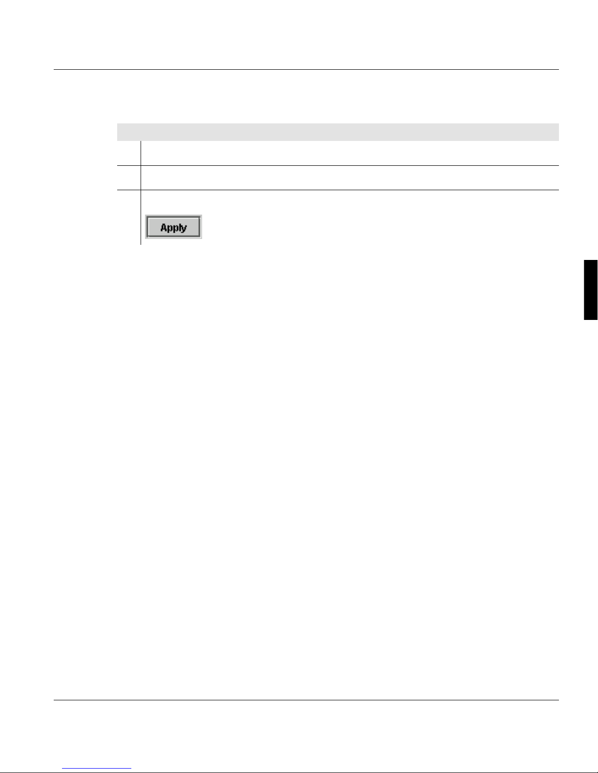
Preset language for user
Proceed as follows:
1. Click on the "User Profile" tab.
2. Select the desired language in the selection list.
3. Click on the following button:
4.3.2 User settings made by the Operator
As an Operator, you can normally make the following user settings:
4.3.2.1 Log on as user and request an access ticket >>> page 70
4.3.2 User settings made by the Operator
4.3.2.2 Change Password >>> page 71
4.3.2.3 Change language >>> page 71
A29246-X17-X-4-7680 / all_allg3.fm 69

4.3.2.1 Log on as user and request an access ticket
4.3.2.1 Log on as user and request an access ticket
To be able to set parameters on the operator panel, you must first log on as a user and then
request the access ticket.
The access ticket ensures that parameters are not set by different users at parallel operator
panels.
Note
If a user with a higher authorization level has already requested the access ticket, a
message will be displayed. From users with the same authorization level the access
ticket can be requested directly.
Proceed as follows:
1. Click the <General> <User> <Change user> menu.
2. Select the desired user in the selection list.
3. Enter password.
4. Click on the following button:
Only if several operator panels are connected to the printing system:
5. Click on the <General> <Access ticket> menu.
6. Click on the following button:
If the access ticket has already been requested, the button is deactivated.
Note
The access ticket can also be requested and released directly using the following buttons in the frame toolbar without going through the menu.
70 A29246-X17-X-4-7680 / all_allg3.fm
4.3.2.2 Change Password
Proceed as follows:
1. Click the <General> <User> <User profile> menu.
2. Click on the "Password" tab.
3. Enter the old password and then enter the new password twice.
The password may consist of any characters.
4. Click on the following button:
4.3.2.3 Change language
4.3.2.2 Change Password
Proceed as follows:
1. Click the <General> <User> <User profile> menu.
2. Click on the "User Profile" tab.
3. Select the desired language in the “Language” selection list.
4. Click on the following button:
A29246-X17-X-4-7680 / all_allg3.fm 71

4.3.2.3 Change language
72 A29246-X17-X-4-7680 / all_allg3.fm

4.3.3 Configure parameters
All parameters of the printing system can be set at the operator panel. The following
prerequisites have to be satisfied:
• The necessary rights are available. These rights are allocated by the respective "Key
operator" in the <Edit user> menu(see section 4.3.1.3 Edit user, page 67).
• The access ticket for this operator panel is requested(see section 4.3.2.1 Log on as user
and request an access ticket, page 70).
• The printing system is in the "stop" or "error" state. With printing system running, the
parameters can only be checked but not reset.
The following steps have to be carried out to set parameters:
4.3.3.1 Select settings and enter values >>> page 73
4.3.3.2 Applying or resetting parameters >>> page 74
4.3.3 Configure parameters
4.3.3.1 Select settings and enter values
You can select predefined settings and values from different operating elements, such as
selection lists, option buttons, check boxes, slides etc.
Example: Select unit for format width
The first click or finger touch opens the pick list.
You can enter new values in input fields via the keyboard.
Example: Entering the IP address
A29246-X17-X-4-7680 / do405.fm 73

4.3.3.2 Applying or resetting parameters
4.3.3.2 Applying or resetting parameters
If you change parameters in a menu, you have to confirm these changes before switching
to another menu.
Button Function
The parameters are applied.
The parameters are not applied; instead the parameters in place
before the change are restored.
If you change to another menu without applying the changed parameters, the following
query is displayed:
Button Function
The parameters are applied and the new menu opens.
The parameters are not applied; instead the previous parameters are
restored.
Then the new menu is opened.
The parameters are not applied.
The menu remains open.
74 A29246-X17-X-4-7680 / do405.fm

4.3.4 Working with wizards
The <wizards> menu in the operator panel makes it quick and easy to configure the printing
system.
The following wizards are available:
• Job wizard for configuring the printing system,
see section 4.3.4.1 Calling up and operating the Job wizard., page 77
• Paper wizard for setting up new paper
see section 4.3.4.2 Calling up and operating the Paper wizard., page 79
• Format wizard for setting up a new paper format
see section 4.3.4.3 Calling up and operating the Format wizard., page 80
Each wizard guides you step by step through a predefined set of dialogs. Dialog text
highlighted in color indicates what kind of settings you are making.
You can use a navigation bar to page back and forth within the process, pause or cancel
the wizard, and reset the settings in the current dialog. As soon as you (a user) have an
access ticket, you can apply the settings at the end.
4.3.4 Working with wizards
Notice text
Menu display
Navigation bar
Notice
Detailed information on dialog control elements is available directly in the control
panel via the context-sensitive Direct Help. The context-sensitive help system can
be called up by selecting the relevant control element and then pressing the F1 key.
A29246-X17-X-4-7680 / do405.fm 75
4.3.4 Working with wizards
Other information:
Stop wizard (pause) >>> page 76
Continuing the procedure >>> page 76
Reset settings per dialog >>> page 76
Apply settings >>> page 77
Stop wizard (pause)
You can stop the wizard at any time and select other menus from the menu tree.
Notice
While the wizard is paused, do not select any menus that are managed in the wizard.
If you attempt to select any of these menus, a corresponding warning will appear.
Proceed as follows:
1.
Press .
2. Select the desired menu on the operator panel.
Continuing the procedure
Proceed as follows:
1. Select the <Wizard> menu on the operator panel.
2.
Press .
The wizard will begin with the dialog where it was stopped.
3.
Press .
The wizard will be continued with all previous settings.
Reset settings per dialog
You can reset the settings of every individual dialog in the wizard.
76 A29246-X17-X-4-7680 / do405.fm

Proceed as follows:
1.
Press . Only the settings for the currently displayed dialog will be
reset. The previous and subsequent dialogs will not be changed.
Apply settings
The settings for the printing system can be applied at the end of every procedure:
Proceed as follows:
1.
Press .
4.3.4.1 Calling up and operating the Job wizard.
4.3.4.1 Calling up and operating the Job wizard.
With the Job wizard, you can configure the printing system in a predefined order of steps.
Proceed as follows:
1. On the operator panel, select the <VarioPrint> <Wizard> menu.
2. Select the option "Job wizard" in the dialog.
3.
Press .
The first dialog in the Job wizard is the setup dialog, (see section Load setup, page
78)
4.
Click on to call up the next dialog.
The following sections explain individual menus of the Job wizard:
• Load setup >>> page 78
• Save settings in the setup >>> page 78
• Stop wizard (pause) >>> page 76
• Continuing the procedure >>> page 76
A29246-X17-X-4-7680 / do405.fm 77

4.3.4.1 Calling up and operating the Job wizard.
• Apply settings >>> page 77
Load setup
The Setup dialog is the first dialog that appears after calling up the Job wizard. If you do not
want to load a setup, click Next to go to the next dialog.
Proceed as follows:
1. Click on the "Display available setups" checkbox.
2. Select the appropriate setup name from the "Available setups" list.
3.
Click on .
The print parameters saved in the selected setup are loaded into the wizard.
Save settings in the setup
You can save the settings that you made with the Job wizard in a new setup. The
associated menu appears as the final dialog in the Job wizard:
Proceed as follows:
1. Click on the "Create new setup" checkbox.
2. Enter a new name in the input field.
78 A29246-X17-X-4-7680 / do405.fm

4.3.4.2 Calling up and operating the Paper wizard.
Proceed as follows:
3.
Press .
The settings will be saved in the setup.
Note
Before you can save settings in an existing setup, you must first have selected the
setup in the first dialog of the wizard. It is not possible to save settings in an existing
setup without having first selected this setup.
4.3.4.2 Calling up and operating the Paper wizard.
Use the Paper wizard to set up new paper.
Note
Existing paper types cannot be changed.
Proceed as follows:
1. On the operator panel, select the <VarioPrint> <Wizard> menu.
2. Select the "Paper wizard" option in the dialog.
3.
Press .
4. Enter a new name in the "Paper name" entry field.
A29246-X17-X-4-7680 / do405.fm 79

4.3.4.3 Calling up and operating the Format wizard.
Proceed as follows:
5.
Select a format from the table and click on .
Alternative:
If you want to create a new format for the newly defined paper:
Press .
Enter the corresponding formats in the Format wizard and apply, (see section 4.3.4.3
Calling up and operating the Format wizard., page 80).
You will return to the Paper wizard.
6. Follow the instructions in the subsequent menus.
7.
Click on in the final menu.
4.3.4.3 Calling up and operating the Format wizard.
Use the Format wizard to set up a new paper format. The Format wizard only has one
menu.
Note
Existing formats cannot be changed, regardless of whether they are predefined or
user-defined.
Proceed as follows:
1. On the operator panel, select the <VarioPrint> <Wizard> menu.
2. Select the "Format wizard" button in the menu display.
3.
Press .
4. Enter a new name in the "Format name" entry field.
5. Set format attributes.
80 A29246-X17-X-4-7680 / do405.fm

Proceed as follows:
6.
Press .
4.3.4.3 Calling up and operating the Format wizard.
A29246-X17-X-4-7680 / do405.fm 81

4.3.5 Starting and confirming the replacement of a consumable or expendable
4.3.5 Starting and confirming the replacement of a consumable or expendable
In the operator panel, you are provided with information on the current status of the printing
system. Warning and/or error messages indicate when consumables or expendables have
to be added or replaced.
You can check the current counter readings at any time in the <Consumables counter>
menu, e. g.:
Column Description
Status
The usage period for this consumable/expendable is below the
warning value. No action required.
or
The warning value for this consumable/expendable has been
exceeded.
The consumable/expendable should be replaced soon.
The accumulated value for this consumable/expendable has been
exceeded.
The consumable/expendable must be replaced.
Counter name Abbreviation for the relevant consumable/expendable.
Counter value Number of pages printed since the last replacement.
Unit The values refer to A4 pages or to 12" pages.
Warning value A warning message appears if this value is reached.
End value An error message appears if this value is reached.
Consumables and expendables that must be replaced by service only are shown as
deactivated.
Every replacement of a consumable or expendable must be started and confirmed in the
operator field, the same applies to parking (= cleaning) corotrons.
82 A29246-X17-X-4-7680 / do405.fm

4.3.5 Starting and confirming the replacement of a consumable or expendable
Requirements:
• the user rights for replacing the developer are available
• the access ticket for this operator field is requested
• the printing system is in "stop" or "error" status, i.e. not printing
• no other change function is being executed.
The following explains the procedure for starting and confirming a replacement using the
example "Empty developer station".
Note
On the detailed procedure see section 7 Replacing consumables and expendables,
page 197.
Proceed as follows:
1. Select the applicable consumable/expendable, here "developer - lower print unit" in
the <Consumable counter> menu:
A29246-X17-X-4-7680 / do405.fm 83

4.3.5 Starting and confirming the replacement of a consumable or expendable
Proceed as follows:
2.
Press .
The relevant menu under <Consumable replacement> is opened, here the <Replace
developer> menu.
The option fields are prefilled depending on the selected consumable/expendable, in
the printer view the consumable/expendable is highlighted in yellow, e. g.:
The printer view can also be completely hidden or shown by clicking the arrow
symbols.
84 A29246-X17-X-4-7680 / do405.fm

4.3.5 Starting and confirming the replacement of a consumable or expendable
Proceed as follows:
3.
Press the button.
A new menu window is opened, displaying the most important operations, e. g.:
A29246-X17-X-4-7680 / do405.fm 85

4.3.5 Starting and confirming the replacement of a consumable or expendable
Proceed as follows:
4. If required, start or confirm individual operations by clicking the checkboxes.
The symbols on the left side show the type of operation in question:
These operations are recorded by sensors of the printing
system.
The progress display is automatically moved forward.
These operations must be started or confirmed by clicking the
checkbox, e.g.
The symbols on the right side indicate the progress:
the displayed action has not been completed or is incorrect.
the displayed action was completed successfully.
The following buttons can be used to toggle between the menu windows:
86 A29246-X17-X-4-7680 / do405.fm

4.3.5 Starting and confirming the replacement of a consumable or expendable
Proceed as follows:
5. After the consumable/expendable has been completely replaced, the replacement
must be confirmed:
The replacement procedure is complete. The counter for this
and/or
consumable/expendable is reset.
The replacement procedure is canceled. The counter for this
and/or
consumable/expendable is not reset.
A29246-X17-X-4-7680 / do405.fm 87

4.3.5 Starting and confirming the replacement of a consumable or expendable
88 A29246-X17-X-4-7680 / do405.fm

5 Operating the printing system
5.1 Overview
This section explains how to turn the printing system on and off, how to fill, remove and
change the paper, and how to set up a print job. For printing with two colors (Océ Custom
Tone option), replacing the developer station is described in detail.
You will find information on the following topics:
5.2 Powering on the printing system >>> page 90
5 Operating the printing system
5.3 Paper specifications >>> page 91
5.4 Refilling paper >>> page 93
5.5 Removing paper from the output tray >>> page 96
5.6 Replacing paper >>> page 99
5.7 Setting up a print job >>> page 111
5.8 Power off the printing system >>> page 119
5.9 Printing with Two Colors >>> page 120
A29246-X17-X-4-7680 / do501.fm 89

5.2 Powering on the printing system
5.2 Powering on the printing system
Proceed as follows:
1. Close all input trays and output trays.
2. Open the center right door.
3. Turn the main power switch to the "I"
I
position.
For the exact location of the main
switch, see also 3.2.3 Internal view
>>> page 33.
4. Close the door.
5. Press the on key.
Different messages appear in the
operator panel after a while.
After booting, the current status
information of the printing system is
displayed in the operator panel.
6. Making the necessary adjustments on the operator panel.
90 A29246-X17-X-4-7680 / do501.fm
 Loading...