

Page 1

Océ
User manual
Arizona T220UV
Océ Arizona T220UV User Guide
Page 2

Order number 3010102780
Edition Revision C
US
Page 3

Table of Contents
Chapter 1
Introduction . . . . . . . . . . . . . . . . . . . . . . . . . . . . . . . . . . . . . . . . . . . . . . . . . . . . . . . 5
Preface. . . . . . . . . . . . . . . . . . . . . . . . . . . . . . . . . . . . . . . . . . . . . . . . . . . . 6
Product Compliance. . . . . . . . . . . . . . . . . . . . . . . . . . . . . . . . . . . . . . . . . . 9
Chapter 2
Product Overview . . . . . . . . . . . . . . . . . . . . . . . . . . . . . . . . . . . . . . . . . . . . . . . . . 11
General Description . . . . . . . . . . . . . . . . . . . . . . . . . . . . . . . . . . . . . . . . . 12
Product Features . . . . . . . . . . . . . . . . . . . . . . . . . . . . . . . . . . . . . . . . . . . 14
Chapter 3
Safety Information. . . . . . . . . . . . . . . . . . . . . . . . . . . . . . . . . . . . . . . . . . . . . . . . . 17
Safety Guidelines. . . . . . . . . . . . . . . . . . . . . . . . . . . . . . . . . . . . . . . . . . . 18
UV Lamp Safety. . . . . . . . . . . . . . . . . . . . . . . . . . . . . . . . . . . . . . . . . . . . 22
Arizona T220UV Safety Labels . . . . . . . . . . . . . . . . . . . . . . . . . . . . . . . . 24
Safety Awareness . . . . . . . . . . . . . . . . . . . . . . . . . . . . . . . . . . . . . . . . . . 27
Table of Contents
Chapter 4
User Interface. . . . . . . . . . . . . . . . . . . . . . . . . . . . . . . . . . . . . . . . . . . . . . . . . . . . . 33
Operator Control Panel . . . . . . . . . . . . . . . . . . . . . . . . . . . . . . . . . . . . . . 34
Menu Structure . . . . . . . . . . . . . . . . . . . . . . . . . . . . . . . . . . . . . . . . . . . . 39
Chapter 5
How to Operate the Arizona T220UV . . . . . . . . . . . . . . . . . . . . . . . . . . . . . . . . . . 45
Training Requirements. . . . . . . . . . . . . . . . . . . . . . . . . . . . . . . . . . . . . . . 46
How to Switch the Printer On . . . . . . . . . . . . . . . . . . . . . . . . . . . . . . . . . 47
How to Set Up a Print Job . . . . . . . . . . . . . . . . . . . . . . . . . . . . . . . . . . . . 51
Select a Print Job . . . . . . . . . . . . . . . . . . . . . . . . . . . . . . . . . . . . . . . . 51
Change Print Job Settings . . . . . . . . . . . . . . . . . . . . . . . . . . . . . . . . . 52
Change Print Job Parameter Options . . . . . . . . . . . . . . . . . . . . . . . . . 53
How to Use the Media Vacuum . . . . . . . . . . . . . . . . . . . . . . . . . . . . . . . . 55
The Media Vacuum System . . . . . . . . . . . . . . . . . . . . . . . . . . . . . . . . 55
How to Maintain Print Quality. . . . . . . . . . . . . . . . . . . . . . . . . . . . . . . . . . 57
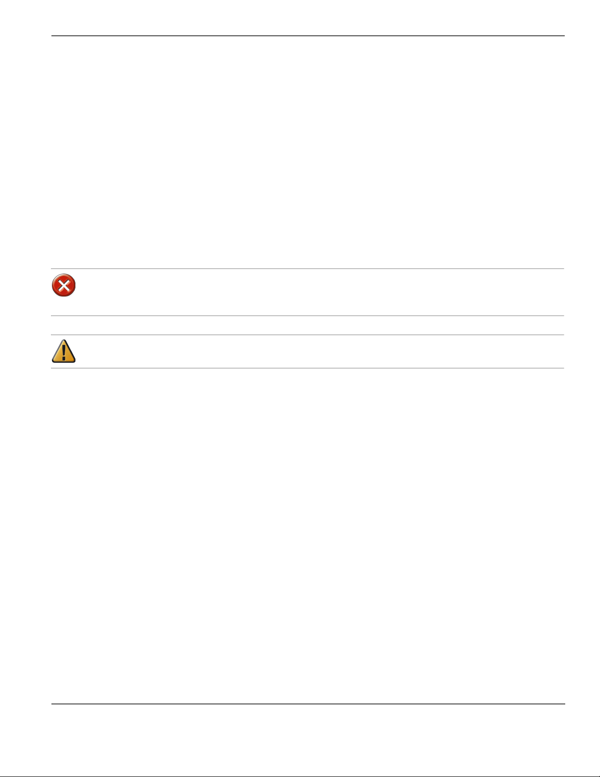
How to Reduce Banding . . . . . . . . . . . . . . . . . . . . . . . . . . . . . . . . . . . 57
Diagnostic Stripe. . . . . . . . . . . . . . . . . . . . . . . . . . . . . . . . . . . . . . . . . 58
Standard Nozzle Print . . . . . . . . . . . . . . . . . . . . . . . . . . . . . . . . . . . . . 62
Diagnostic Nozzle Print. . . . . . . . . . . . . . . . . . . . . . . . . . . . . . . . . . . . 64
Application Hints and Tips. . . . . . . . . . . . . . . . . . . . . . . . . . . . . . . . . . 65
Chapter 6
Ink System Management. . . . . . . . . . . . . . . . . . . . . . . . . . . . . . . . . . . . . . . . . . . . 69
Océ T220UV Ink . . . . . . . . . . . . . . . . . . . . . . . . . . . . . . . . . . . . . . . . . . . 70
How to Change an Ink Bottle . . . . . . . . . . . . . . . . . . . . . . . . . . . . . . . . . . 71
How to Scan Ink Barcodes. . . . . . . . . . . . . . . . . . . . . . . . . . . . . . . . . . . . 73
How to Empty the Waste Bottle . . . . . . . . . . . . . . . . . . . . . . . . . . . . . . . . 74
How to Change Blot Cloth . . . . . . . . . . . . . . . . . . . . . . . . . . . . . . . . . . . . 75
3
Page 4

Table of Contents
Chapter 7
Media Management . . . . . . . . . . . . . . . . . . . . . . . . . . . . . . . . . . . . . . . . . . . . . . . . 79
How to Handle Media. . . . . . . . . . . . . . . . . . . . . . . . . . . . . . . . . . . . . . . . 80
How to Use Media Holder Strips . . . . . . . . . . . . . . . . . . . . . . . . . . . . . . . 82
Use A Spoilboard Sheet to Reduce Artifacts . . . . . . . . . . . . . . . . . . . . . . 83
Chapter 8
Error Handling and Troubleshooting. . . . . . . . . . . . . . . . . . . . . . . . . . . . . . . . . . 85
Troubleshooting Overview . . . . . . . . . . . . . . . . . . . . . . . . . . . . . . . . . . . . 86
Troubleshooting Tips . . . . . . . . . . . . . . . . . . . . . . . . . . . . . . . . . . . . . . . . 88
System Errors . . . . . . . . . . . . . . . . . . . . . . . . . . . . . . . . . . . . . . . . . . . . . 90
T220UV Lamp Bulb Replacement . . . . . . . . . . . . . . . . . . . . . . . . . . . . . . 91
Chapter 9
Printer Maintenance . . . . . . . . . . . . . . . . . . . . . . . . . . . . . . . . . . . . . . . . . . . . . . 101
Maintenance Guidelines. . . . . . . . . . . . . . . . . . . . . . . . . . . . . . . . . . . . . 102
As Required Maintenance . . . . . . . . . . . . . . . . . . . . . . . . . . . . . . . . . . . 103
Remove Ink and Ink Waste . . . . . . . . . . . . . . . . . . . . . . . . . . . . . . . . 103
Clean Carriage Underside. . . . . . . . . . . . . . . . . . . . . . . . . . . . . . . . . 104
Swab Printheads . . . . . . . . . . . . . . . . . . . . . . . . . . . . . . . . . . . . . . . . 105
Monthly Maintenance . . . . . . . . . . . . . . . . . . . . . . . . . . . . . . . . . . . . . . . 107
Clean Gantry Rails . . . . . . . . . . . . . . . . . . . . . . . . . . . . . . . . . . . . . . 107
Clean Gantry Door Fans . . . . . . . . . . . . . . . . . . . . . . . . . . . . . . . . . . 108
Clean Ozone Filters. . . . . . . . . . . . . . . . . . . . . . . . . . . . . . . . . . . . . . 108
Annual Maintenance . . . . . . . . . . . . . . . . . . . . . . . . . . . . . . . . . . . . . . . 110
Change Auto-Drain Air Filter . . . . . . . . . . . . . . . . . . . . . . . . . . . . . . . 110
Clean Linear Encoders . . . . . . . . . . . . . . . . . . . . . . . . . . . . . . . . . . . 111
Change the Electronics Bay Air Filter . . . . . . . . . . . . . . . . . . . . . . . . 112
Gantry Brushes (Every Two Years). . . . . . . . . . . . . . . . . . . . . . . . . . 113
Appendix A
Special Prints . . . . . . . . . . . . . . . . . . . . . . . . . . . . . . . . . . . . . . . . . . . . . . . . . . . . 115
How to Install Special Prints. . . . . . . . . . . . . . . . . . . . . . . . . . . . . . . . . . 116
How to Print the Menu Tree . . . . . . . . . . . . . . . . . . . . . . . . . . . . . . . . . . 117
How to Print the Table Grid . . . . . . . . . . . . . . . . . . . . . . . . . . . . . . . . . . 118
Appendix B
Safety Systems and Machine Safeguarding . . . . . . . . . . . . . . . . . . . . . . . . . . . 119
Arizona T220UV Safety Systems. . . . . . . . . . . . . . . . . . . . . . . . . . . . . . 120
Interlock System Test Procedure . . . . . . . . . . . . . . . . . . . . . . . . . . . . . . 122
4
Page 5

Chapter 1 Introduction
5
Page 6

Preface
Preface
Summary
This User Guide introduces you to the Océ Arizona T220UV flatbed inkjet printer. It will orient you to the many
features and procedures that enable you to print quality images on various media.
Copyright
© 2004 Océ Display Graphics Systems. All rights reserved.
This document contains information proprietary to Océ, to its subsidiaries, or to third parties to which Océ may have
a legal obligation to protect such information from unauthorized disclosure, use or duplication. Any disclosure, use,
or duplication of this document or of any of the information contained herein for other than the specific purpose for
which it was disclosed is expressly prohibited, except as Océ may otherwise agree to in writing. Due to continuing
research and product improvements, features or product specifications may change at any time without notice.
Océ DGS on the Internet
For further information on documentation and support for your Arizona T220UV or for information on other Océ
Display Graphics Systems products, please visit our web site:
Web: http://www.dgs.oce.com
Safety Information
This manual contains three sections with details on safety when handling ink and using the printer:
■ "Ink Safety" offers advice in the proper handling of UV inks;
■ "UV Lamp Safety" presents warning about the dangers of exposure to UV light; and
■ "Safety Interlocks" explains the safety features built in to the printer that prevent exposure to UV light.
Also, where applicable, cautions and warnings are used throughout this manual to draw your attention to safety
precautions to be taken.
Customer Support
Océ maintains a comprehensive support structure for its Arizona T220UV customers. Upon installation of your
printer, you will be provided with the name of the sales and service office responsible for your account. Record this
information, along with the serial number of your Arizona T220UV. Always report service problems to the office
assigned to your account at installation.
6 Chapter 1 Introduction
Page 7

Customer Service
When you call our customer service number you will be provided with telephone technical support. Outside of
office hours, you can leave a message and your call will be returned the next working day. When you call, identify
yourself as an Arizona T220UV customer and provide the following information:
• The serial number of your Arizona T220UV
• Your company name and your name
• Your telephone number
• Nature of the problem
If we are unable to resolve your problem over the telephone, field engineers can be dispatched to your site to
conduct repairs. Service visits are paid for by the customer, either under a maintenance agreement, by purchase
order or prepayment. Time and material rates are charged for any service not covered under a maintenance
agreement. Before calling to report a problem, gather as much information about the problem as possible and have
it ready to provide to the customer care center engineer. The more information you can provide initially, the more
quickly the problem can be corrected.
Responsibilities of the T220UV Operator
The operator of the Arizona T220UV must be properly trained. Océ provides training for the operator in the use of
the Arizona T220UV hardware and software at the time of installation. It is the customer's responsibility to ensure
that only properly trained personnel operate the printer.
Preface
Operators of the Arizona T220UV should be fully versed in the operation of Onyx PosterShop® . For any operator
unfamiliar with its operation, Onyx PosterShop® training is required. On-site or off-site training courses are
available; contact Onyx Graphics Corporation for more information:
http://www.onyxgfx.com/support_training.html
The operator or other trained personnel are expected to handle all user maintenance as detailed in the User Guide,
and also replacement of consumable parts (except print heads). If your site has a technician in charge of printer
maintenance, that person is the optimal candidate. While any trained operator may perform routine maintenance,
the best maintenance results from familiarity with the printer's internal operation and history.
The Arizona T220UV printer requires some daily maintenance. Periodic cleaning must be scheduled for some
components on a weekly basis. A few minutes spent cleaning ensures the highest quality prints. Several areas
require maintenance to ensure the highest print quality, and the printer design gives you easy access to all these
areas. Refer to the Arizona T220UV User Guide for details.
It is the responsibility of the operator to try to eliminate simple problems before calling a service representative.
But knowing when to call for service is also important. An untrained operator must not attempt to service the printer
as this may cause further damage. When you have determined that a service call is required, call as soon as possible.
See the Maintenance section for more details.
7
Page 8

Preface
Responsibilities of the T220UV Service Technician
Field service technicians must have Océ Arizona T220UV service training. The service technician is responsible
for all repairs, upgrading and modification requested by the customer or mandated by the Océ Service and Support
Group.
Service personnel are furnished with proper tools for the installation and maintenance of the Arizona T220UV
printer. In addition to the T220UV tools and custom kits, each engineer will have basic tools for proper maintenance
and servicing.
An Océ help desk consultant initially screens all customer calls. This means that a trained Océ Arizona T220UV
specialist with system training handles the calls and helps you understand your problem or situation. This process
minimizes the number of print quality issues that are not directly related to hardware. All hardware problems are
dispatched to field service technicians. If an on-site visit is required, the help desk technician can recommend parts
which then can be ordered, thus increasing efficiency in the service cycle.
Statement of Foreseen Use
The Océ Arizona T220UV flatbed inkjet printer uses piezo printing technology and UV curable inks to produce
outdoor-durable output. It can print directly onto rigid and flexible substrates up to 62 inches wide by 120 inches
long by 2 inches thick (1.6 m x 3 m x 5 cm).
The Océ Arizona T220UV holds substrates stationary while the print head assembly moves across to create the
print, eliminating image skew problems associated with rigid stock feed systems. It can print full bleeds, saving
time and labor costs in finishing.
With four print heads per color, the Océ ArizonaT220UV can produce prints at a production speed of up to 180
square feet (16.7 m2) per hour. It includes the unique Océ ColorBlend® super-CMYK technology, for an apparent
resolution of 600 dpi. The Océ Arizona T220UV uses UV curable pigmented inks, and can print directly onto a
variety of uncoated rigid or flexible substrates such as foam-core style mounting board, PVC sheets, styrene,
aluminum-plastic composites and vinyl.
Note: "Océ ColorBlend" is a registered trademark of Océ Display Graphics Systems, Inc.
8 Chapter 1 Introduction
Page 9
Product Compliance
Introduction
Electromagnetic Compatibility:
This equipment generates, uses and radiates radio frequency energy and if not installed and used as designed or
intended, may cause interference to radio communications. This equipment has been tested and found to comply
with the limits for a Class A computing device. This equipment has been designed to provide reasonable protection
against such interference when operated in residential and commercial environments. Operation of this equipment
in a residential area may cause interference, in which case the user, at his own expense, is required to take whatever
measures are required to correct the interference.
The Arizona T220UV complies to the following Agencies and Standards:
[1]
[1] Compliance Specifications
Specification Directive Number
Product Compliance
EMC
(Directive 89/336/EEC)
Electrical Safety
(Low Voltage Directive 73/23/EEC)
Compliance Category
This device complies with Class A emmision limits.
This equipment is considered to be information technology equipment for use in a light industrial setting. The
equipment falls under the scope of the Machinery Directive due to the movement associated with the gantry
carrying the printer head carriage assembly. As such, a full risk assessment per EN 1050 and a full mechanical and
machinery assessment per 292-2 + A1 Annex 1 was performed. As the equipment is primarily information
technology equipment (large format printer receiving data from a computer terminal), and is within the scope of
EN 60950 (mains operated ITE equipment under 600V including plotters and photoprinters - clause 1.1.1, EN
60950: 2000), a full electrical evaluation was performed per EN 60950:2000.
Noise Measurement Test Summary
Tested according to EN13023:2003, EN11204, ISO3744:1994(E)/ISO3746:1995(E) and declared according to
ISO4871:1984(E)
Measurements taken at the sample in 5 different locations, Printer in normal operation with Vacuum Pump, exceed
75dB (maximum measured value: 76.8dB). For all locations, provide noise protection enclosure or remove pump
from location.
Complete report is available upon request:
Colin Soutar
Health, Safety and Environment
Océ Display Graphics Systems (ODGS)
13231 Delf Place Building #501
Richmond, British Columbia.
Canada V6V 2C3
Email: colin.soutar@dgs.oceusa.com
EN61000-6-4
EN61000-6-2
EN61000-3-3 1995+A1
EN55011
EN60950: 2000(A1 thru A4, A11)
IEC 60950, UL60950, CAN/CSA 22.2 No. 60950-00
EN60204-1:2001
9
Page 10

Product Compliance
Manufacturer:
Oce Display Graphics Systems (ODGS)
13231 Delf Place - Building #501
Richmond, British Columbia
Canada V6V 2C3
Contact: Colin Soutar
Email: colin.soutar@dgs.oceusa.com
http://www.oceusa.com/
http://www.dgs.oce.com/ (
Direct Dial (604) 232-2345
Fax (604) 273-2775
Alternate Manufacturer:
Océ Display Graphics Systems (ODGS)
San Jose Office (RasterGraphics)
2811 Orchard Parkway San Jose, California
U.S.A. 95134
Ph: 408 232 4000
Fx: 408 232 4100
Representatives Marketing the Arizona T220 in Europe:
Océ-Deutschland GmbH
Solinger Straße 5-7
45481 Mülheim/Ruhr
Germany
Telephone: (49) 2084 8450
Fax: (49) 2084 80950
E-mail: ves@oce.de
Web site: http://www.oce.de/
Océ (UK) Ltd.
Langston Road Loughton, Essex IG10 3SL
United Kingdom
Telephone: (44) 870 600 5544
Fax: (44) 870 600 1113
E-mail: salesinformation@oce.co.uk
Web site: www.oce.co.uk
10 Chapter 1 Introduction
Page 11

Chapter 2 Product Overview
11
Page 12
General Description
General Description
Introduction
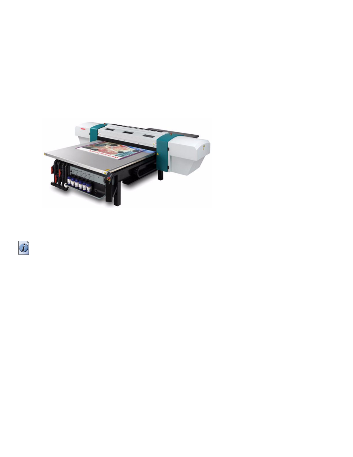
The Arizona T220UV is a six-color digital inkjet printer capable of producing large format images on various rigid
and flexible stock materials. The printer consists of a large vacuum table and moving gantry. The material is held
flat and stationary on the vacuum table during printing. The gantry contains a carriage that sweeps across the table
as the gantry moves in steps along the length of the table to print an image on the media. The Arizona T220UV
must be operated in accordance with certain environmental and safety requirements noted in this document.
Illustration
[1]
[1] Arizona T220UV Printer
Viewing Specifications (8 pass mode only)
Note: This viewing specification is based on the Océ reference print, imaged on the provided Indoor/Outdoor
Poster Grade Paper (Part # 3010102610).
Banding artifacts - not visible from 8 feet (Texture or Regular Banding).
Non-Banding artifacts - not visible from 3 feet (fisheyes, orange peel).
12 Chapter 2 Product Overview
Page 13

Océ ColorBlend® Six-Color Printing
Océ ColorBlend® technology uses the printer’s fifth and sixth ink stations to provide the appearance of continuous
tone color. It does this by adding lighter density cyan and magenta inks to the basic four CMYK (cyan, magenta,
yellow and black) inks to create a smoother appearance in the light and midtone colors, a wider color gamut and
crisper detail. The result is near-photographic quality output without the requirement of extremely high resolution
or true continuous tone.
[2]
[2]
Note: Océ ColorBlend is a registered trademark of Océ Display Graphics Systems, Inc.
General Description
13
Page 14
Product Features
Product Features
Introduction
The Arizona T220UV prints directly onto rigid media using an original flatbed technology. The printer holds the
media stationary on the table while printing is in progress. In addition to the benefits of stationary positioning, the
use of UV ink technology on rigid material eliminates finishing processes such as mounting and lamination.
T220UV Specifications
[3]
Feature: Specification:
Minimum Media Size 6" wide x 6" long (15cm x 15cm)
Maximum Media Size 62" wide x 120" long (158cm x 305cm)
Maximum Media
Thickness
Resolution 309 dpi (600 apparent dpi)
Nozzle Drop Volume 65 picoliter
Productivity 4 pass mode: 180 sq.ft./hr. (16.7 sq.metres/hr.)
Ink Colors Black, Cyan, Light Cyan, Magenta, Light Magenta, Yellow
Print Heads Piezoelectric (504 nozzles per color) Xaar/MIT
Curing System UV curing lamp
Table Protection Replaceable liner to protect table from UV inks
Weight 2300 lbs. (1043 kg.)
Dimensions Table: 70.5" x 168" (180 cm x 427 cm)
Hardware Interface Standard Centronics Parallel, LVD, SCSI-2, Ethernet TCP/IP and RS-232 Serial Ports
Software Onyx PosterShop 6.0 or greater
Air Requirements
Pressure: .........80 to 100 psi per minute
2" (5.8cm) thick
8 pass mode: 90 sq.ft./hr. (8.4 sq.metres/hr.)
Gantry: 36" x 120" (91 cm x 305 cm)
Flow: .........1cfm per minute
Air supplied to the printer must pass through the supplied Air Preparation Unit that contains the following:
■ Air Filter – 5 micron element c/w auto drain;
■ Coalescing Filter – 99.97% efficiency c/w auto drain; and
■ Regulator c/w gauge.
14 Chapter 2 Product Overview
Page 15

Printer Electrical Configuration
The T220UV printer operates in the following two configurations:
Delta (USA) Configuration:
Voltage: 230VAC +/-10%, 3 Phase
Frequency: 50 or 60 Hz
Current: 25AMPS maximum steady state
Power: 15kW max.
Circuit Breaker 30 Amps
Wye (European) Configuration:
Voltage: 400VAC +/-10%, 3 Phase
Frequency: 50 or 60 Hz
Current: 25AMPS maximum steady state
Power: 15kW max.
Circuit Breaker 30 Amps
Vacuum Pump Configuration
The vacuum pump operates over the following range of voltages and frequencies:
230 Volts @ 60HZ
Voltage: 230 VAC +/-10%, 3 Phase
Current: 13 AMPS maximum steady state
Power: 6 kW max.
Circuit Breaker 20 Amps
400 Volts @ 60Hz
Voltage: 400 VAC +/-10%, 3 Phase
Current: 8 AMPS maximum steady state
Power: 6 kW max.
Circuit Breaker 15 Amps
190 Volts @ 50 Hz
Voltage: 190 VAC +/-10%, 3 Phase
Current: 16.5 AMPS maximum steady state
Power: 8 kW max.
Circuit Breaker 20 Amps
380 Volts @ 50 Hz
Voltage: 380 VAC +/-10%, 3 Phase
Current: 8 AMPS maximum steady state
Power: 7kW max.
Circuit Breaker 15 Amps
Product Features
Note: ODGS recommends that the AC power outlet for the vacuum pump be located within 8 feet of the power inlet
on the pump.
Important: Unplugging the power cord from the wall socket is the only way to isolate the entire machine.
15
Page 16

Product Features
16 Chapter 2 Product Overview
Page 17

Chapter 3 Safety Information
17
Page 18
Safety Guidelines
Safety Guidelines
Introduction
Read all of the material in this section and review the MSDS documents before handling any UV ink or using the
T220 UV printer.
Caution: Both UV inks and the curing lamps can be harmful if not properly handled. Follow these
guidelines carefully in order to ensure maximum safety.
Personal Safety
The operator should wear butyl rubber gloves, a protective apron, a NIOSH-approved respirator (half-mask organic
vapor respirator), and Safety glasses with side shields when handling inks.
Personal Safety
The Arizona T220UV printer has an integrated safety interlock system that stops all machine motion when a
situation that might compromise operator safety occurs. Thus, opening any of the gantry doors (except during
authorized procedures), tripping the hinged gate on the gantry cover, or activating an Emergency-Stop button will
switch the Safety Monitoring Relay input circuits. This results in the system isolating the power to both the motion
control motors and the T220UV curing system (lamps). For a general description of how the safety interlock system
works, see “Safety Interlocks” and for a detailed technical description see Appendix B.
Handling UV Inks
Read and practice safety guidelines as outlined in the Material Safety Data Sheet (MSDS) for each ink. Post these
documents in the work area as required by prevailing law. MSDS for all six inks are provided when you purchase
inks. The following is a summary of the important safety aspects of the MSDS that are common to all UV inks.
Immediate Health Effects of Exposure to Ink
[4]
[4] Immediate (Acute) Health Effects by Route of Exposure
Exposure by: Effect:
Inhalation: Can cause severe respiratory irritation, dizziness, weakness, fatigue, nausea, headache and
Skin Contact: Can cause severe irritation, defatting, and dermatitis. Irritation effects may last for hours or days
Eye Contact: Corrosive to eye tissue. Can cause severe irritation, tearing, and burns that can quickly lead to
Ingestion: Severely irritating to mouth, throat, and stomach. Can cause abdominal discomfort, nausea,
possible unconsciousness.
but will not likely result in permanent damage.
permanent injury including blindness.
vomiting and diarrhea.
18 Chapter 3 Safety Information
Page 19
Safety Guidelines
Long-Term Health Effects
[5]
[5] Long-Term (Chronic) Health Effects
Exposure by: Effect
Inhalation: Upon prolonged and/or repeated exposure, can cause severe respiratory irritation, dizziness,
weakness, fatigue, nausea, headache and possible unconsciousness.
Skin Contact: Upon prolonged or repeated contact can cause severe irritation, defatting, and dermatitis. May
cause lingering affects but not likely to result in permanent damage if the exposure is
eliminated. Upon prolonged or repeated exposure, harmful if absorbed through the skin. May
cause severe irritation and systemic damage
First-Aid Measures
[6]
[6] First-aid Measures
Exposure by: Remedy
Inhalation: Remove to fresh air. If breathing is difficult, have a trained individual administer oxygen. If not
breathing, give artificial respiration and have a trained individual administer oxygen. Get
medical attention immediately.
Eyes: Immediately flush eyes with plenty of water for at least 20 minutes retracting eyelids often.
This corrosive material can cause immediate and permanent eye damage. Tilt the head to
prevent chemical from transferring to the uncontaminated eye. Get immediate medical
attention and monitor the eye as advised by your physician.
Skin Contact: Wash with soap and water. Remove contaminated clothing, launder immediately, and discard
contaminated leather goods. Get medical attention immediately.
Ingestion: Severely irritating. Do not induce vomiting. Seek medical attention immediately. Drink 2
glasses of water or milk to dilute.
Dealing With Spilled Ink
[7]
[7] Accidental Release Measures
Personal
Precautions and
Equipment:
Exposure to the spilled material may be severely irritating or toxic. Follow personal protective
equipment recommendations found in Section VIII of this MSDS. Personal protective
equipment needs must be evaluated based on information provided on the MSDS sheet and the
special circumstances created by the spill including; the material spilled, the quantity of the
spill, the area in which the spill occurred, and the expertise of employees in the area responding
to the spill. Never exceed any occupational exposure limits.
19
Page 20
Safety Guidelines
Handling and Storage
[8]
[8] Handling & Storage
Handling
Precautions:
Toxic or severely irritating material. Avoid contacting and avoid breathing the material. Use
only in a well ventilated area. As with all chemicals, good industrial hygiene practices should
be followed when handling this material. Avoid contact with material, avoid breathing dusts or
fumes, use only in a well ventilated area. Wash thoroughly after handling. Do not get in eyes,
on skin or clothing. Remove contaminated clothing and wash before reuse.
Storage
Conditions:
Store in a cool dry place.
Isolate from incompatible materials.
Exposure Controls
[9]
[9] Exposure Controls
Engineering
Measures
Local exhaust ventilation or other engineering controls are normally required when handling or
using this product to avoid overexposure. It is recommended that facilities storing or using this
material be equipped with an eyewash and safety shower.
Personal Protection
[10]
[10] Personal Protection
Area Strategy
Respiratory
Protection:
Follow a respiratory protection program that meets 29 CFR 1910.134 and ANSI Z88.2
requirements whenever work place conditions warrant the use of a respirator. Respiratory
protection may be required in addition to ventilation depending upon conditions of use.
Eye Protection: Wear safety glasses with side shields when handling this product. Wear additional eye
protection such as chemical splash goggles and/or face shield when the possibility exists for
eye contact with splashing or spraying liquid, or airborne material. Do not wear contact lenses.
Have an eye wash station available.
Skin Protection: Avoid skin contact by wearing chemically resistant gloves, an apron and other protective
equipment depending upon conditions of use. Inspect gloves for chemical break-through and
replace at regular intervals. Clean protective equipment regularly. Wash hands and other
exposed areas with mild soap and water before eating, drinking, and when leaving work. Use
of protective coveralls and long sleeves is recommended.
Gloves: Wear impervious material.
20 Chapter 3 Safety Information
Page 21

Disposal of UV Ink
[11]
[11] Disposal Considerations
Safety Guidelines
Disposal
Methods:
Dispose in accordance with Federal, State, Provincial and Local regulations. Material may be
compatible with industrial waste incineration or inclusion in a fuel blending program. This
characterization is subject to approval by your waste management contractor. This material
should be recycled if possible.
21
Page 22

UV Lamp Safety
UV Lamp Safety
Introduction
The Arizona T220UV printer is designed so that direct light from lamps is not visible and bounce (reflected) light
is minimized. UV lamps radiate harmful ultraviolet rays, which can cause serious burns to skin and eyes. While
thermal burns are felt immediately, UV burns are not felt for several hours. Short exposure to lamp radiation can
cause severe burning of skin and eyes. UV burn of the eyes affects the cornea and takes several days to heal. UV
burn is identical to "Welder's burn" and will feel like sand in the eyes that cannot be washed out. The discomfort is
transitory. Extreme caution must be taken - high power UV radiation can cause blindness.
Limited exposure to UV radiation will evoke erythema on normal skin. Such erythema is transitory and will not
produce blistering, nor tanning, as only a small amount of radiation penetrates the Malpighian layer. Extreme
caution must be taken since high power UV radiation can cause severe burns to the skin.
Note: The Arizona T220UV printer has a built-in interlock safety system that shuts down the UV lights if the gantry
doors are opened. This ensures that the operator is not exposed to potentially harmful UV rays from the lamps. The
section “Safety Interlocks” explains the interlock system and how it protects the operator from UV exposure.
Statement of UV Safety
UV Lamps: Superficial eye damage and burning of the skin can occur with even brief exposure to UV light. Serious
injuries can result from prolonged exposure, especially if unshielded. Some UV lamps operate at very high
temperatures (approximately 800° C). For this reason, never touch a lamp which has been in operation. Let the lamp
cool before attempting any maintenance, and then use extreme care in handling the bulbs. Most bulbs contain a small
amount of metallic mercury which is toxic when ingested, handled, or breathed. Therefore, if bulbs are broken, care
should be taken to clean up the spill immediately.
The UV Lamps emit dangerous levels of UV light. Arizona T220UV operators must limit their exposure to
UV/Blue light escaping from beneath the gantry hinged gates. The UV Radiation Hazards of the machine have been
measured according to EN12198 and are at safe levels outside the machine.
Gantry Cover Brush: The Brushes are used as a UV Shield to prevent stray UV light escaping from the front and
back of the gantry, while still allowing adequate media clearance. The brushes must be replaced if they become
contaminated or deformed by any means. The brushes must be replaced at least every two years, or sooner if they
become contaminated or deformed in any way.
Emmision Compliance
Effective UV-irradiance Emmision Category of AzT220UV According to 7.1 of EN12198-1:2000 Category (1)
Effective Irradiance respective the Effective Radiance Emmision Category of AzT220UV According to 7.1 of
EN12198-1:2000 Category (1)
22 Chapter 3 Safety Information
Page 23

Handling UV lamps
Bare skin contact with the UV lamps must be avoided. Replacement lamps must be wiped with the supplied
cleaning solution before placing in service. Compounds from the skin when heated on lamps operating at 600 to
850C will form permanent etching (devitrification) on the quartz surface decreasing UV energy transmission. A
contaminated lamp eventually may overheat, causing premature failure.
When unpacking the lamps, the carton should be opened fully so lamp can be lifted out of packaging with no
twisting or pulling. Unpacking should take place in an area large enough to eliminate the possibility of inadvertently
striking lamp against walls, pillars, pipes, beams or press machinery.
Ozone Safety
Tri-atomic oxygen or ozone (O3) is the only by-product of the UV lamp. It is formed by oxygen being exposed to
254nm wavelengths of UV energy. Ozone is effectively eliminated in the printing area by exhausting air from the
cooling system of the T220UV. Such exhausting involves no danger as the hot gas is very unstable and breaks down
to oxygen rapidly in ducting. Also, the Arizona T220UV printer is equipped with ozone filters located above the
fans in the gantry. These filters ensure that ozone is kept to a minimal safe level.
UV Lamp Safety
23
Page 24
Arizona T220UV Safety Labels
Arizona T220UV Safety Labels
Introduction
The safety labels are placed at strategic locations on the printer to warn the operator of possible dangers and hazards.
It is important to be aware of the meaning of these labels to ensure safe operation of the printer.
Caution: Read and understand all of the safety label descriptions in the table below before operating the
printer.
Safety Labels
[12]
[12] Safety Labels (1 – 3)
Description Label
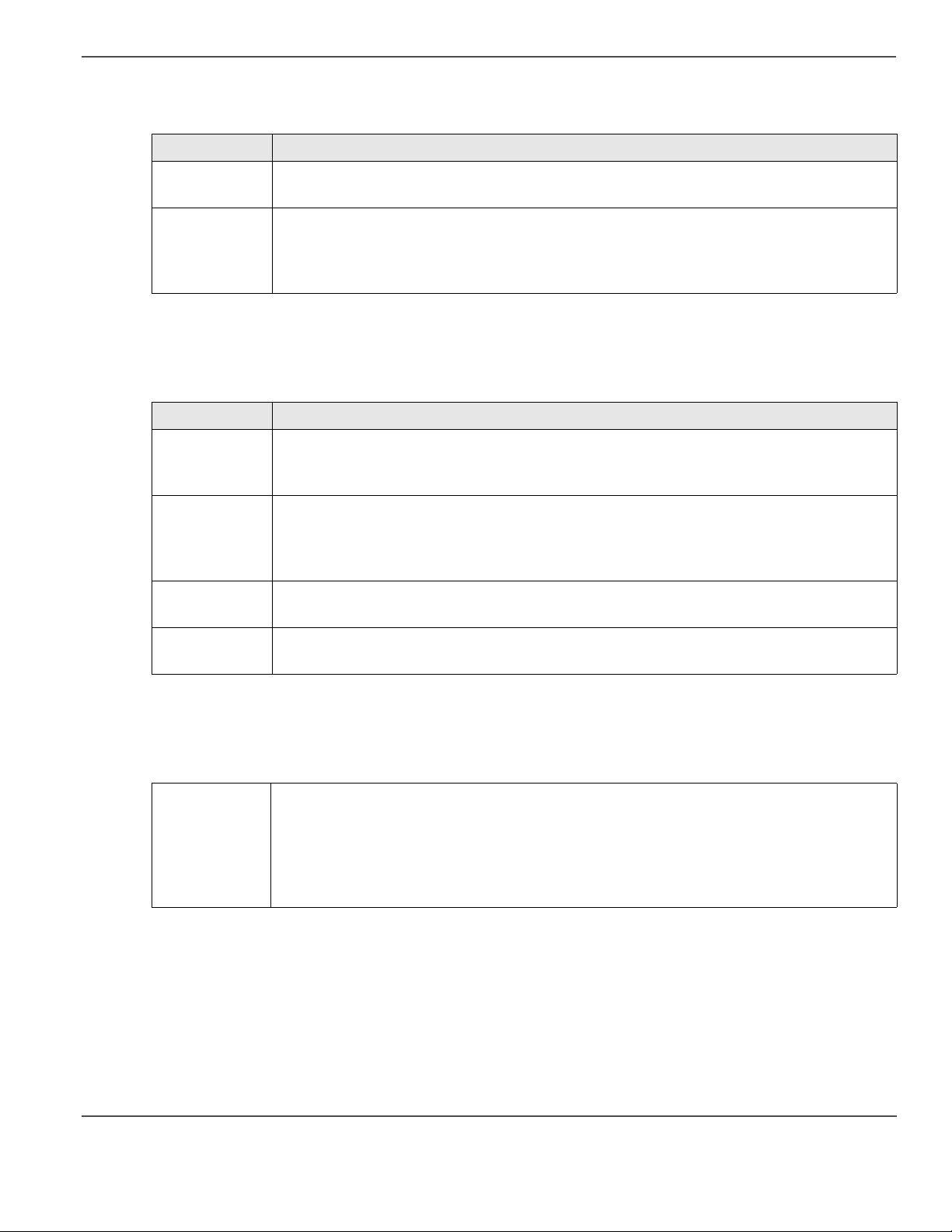
Warning: UV Light Hazard. Avoid looking
[3]
directly at light. # 3012002359
Located on gantry door to remind operator that
looking at the UV light source is dangerous.
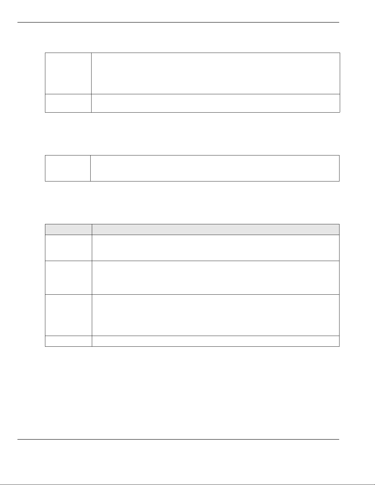
Lifting Hazard, Heavy Object - #3012002361
[4]
Located on the ballast platform to remind service
technicians that the ballast is heavy and to use due
care if any lifting is required.
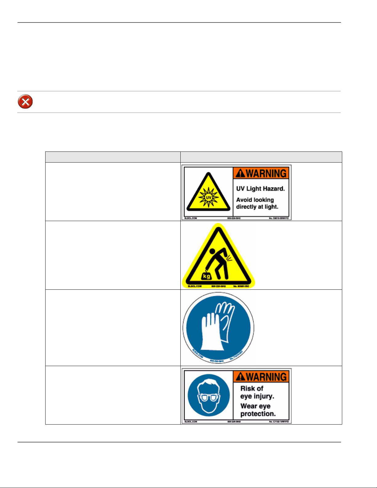
Wear Safety Gloves - # 301222360
[5]
Located on the ink enlcosure tray as a reminder to
always wear gloves when handling ink.
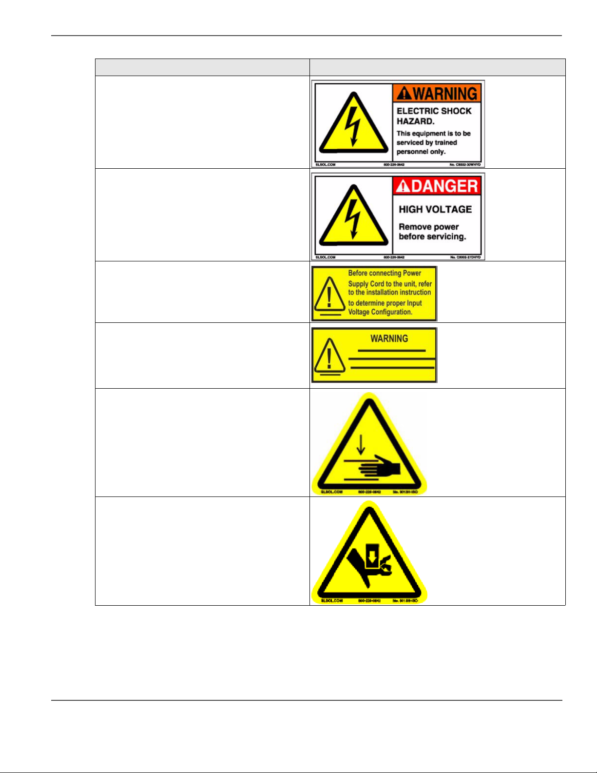
Warning: Risk of Eye Injury. Wear Eye
Protection - #3012002360 - Located on the ink
enclosure tray as a reminder that the UV-curable
ink is harmful to the eyes and skin. Always wear
glasses and gloves when handling ink.
24 Chapter 3 Safety Information
[6]
Page 25
Arizona T220UV Safety Labels
[12] Safety Labels (2 – 3)
Description Label
Warning: Electric Shock Hazard This
[7]
equipment is to be serviced by trained
personnel only. - # 3010100961
Located on the door to the electronics enclosure.
This door must be kept locked and only opened by
a trained technician.
DANGER High Voltage: - # 3010100724
[8]
Remove power before servicing. Located inside
the electronics enclosure. AC power cable should
be disconnected before servicing any electrical
components.
Before connecting Power Supply Cord to the
[9]
unit, refer to the installation instruction to
determine proper Input Voltage Configuration
WARNING - # 3010100315 HIGH LEAKAGE
[10]
CURRENT EARTH CONNECTION
ESSENTIAL BEFORE CONNECTING
SUPPLY.
Located above the AC power cable
[11]
Pinch Point - # 3010100726
Located on the bracket endplate and the plate end
cap.
Crush Hazard - # 3010100725
Located on the gantry end covers
[12]
25
Page 26
Arizona T220UV Safety Labels
[12] Safety Labels (3 – 3)
Description Label
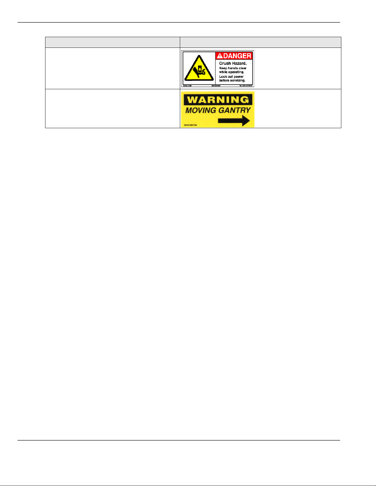
Danger Crush Hazard: - # 3010100725 Keep
[13]
hands clear while operating. Lock out power
before servicing
Located on the endplate of the gantry where the
carriage rests on the capping station.
Warning Moving Gantry - # 3010100756 -
[14]
Located on the table to identify the risk involved
with the gantry moving during printing.
26 Chapter 3 Safety Information
Page 27
Safety Awareness
Introduction
This section contains two sets of principles that must be followed to assure maximum safety when operating the
Arizona T220UV printer. The first set uses negative examples to show you residual risks that must be avoided in
order to prevent injury to the operator. The second set of principles illustrates some of the residual risks that are
inherent in the operation of the Arizona T220UV printer. These are situations or physical aspects of the printer that
may present a potential danger to the operator, but would compromise the capabilities of the printer if changed.
Therefore, they are pointed out as a precaution that the operator must be aware of when using the printer.
Attention: The photos in the following table illustrate residual risks that must be avoided when operating the
Arizona T220UV printer.
Situations to Avoid
Avoid the actions and situations presented in the following table.
[13]
[13] How NOT to use the Arizona T220UV (1 – 2)
Safety Awareness
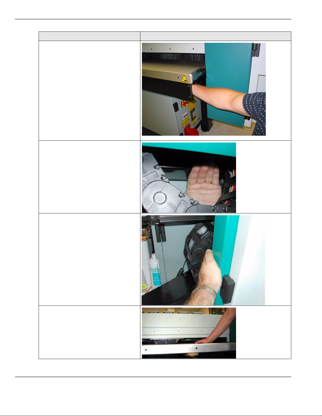
Avoid these Situations For Your Personal Safety
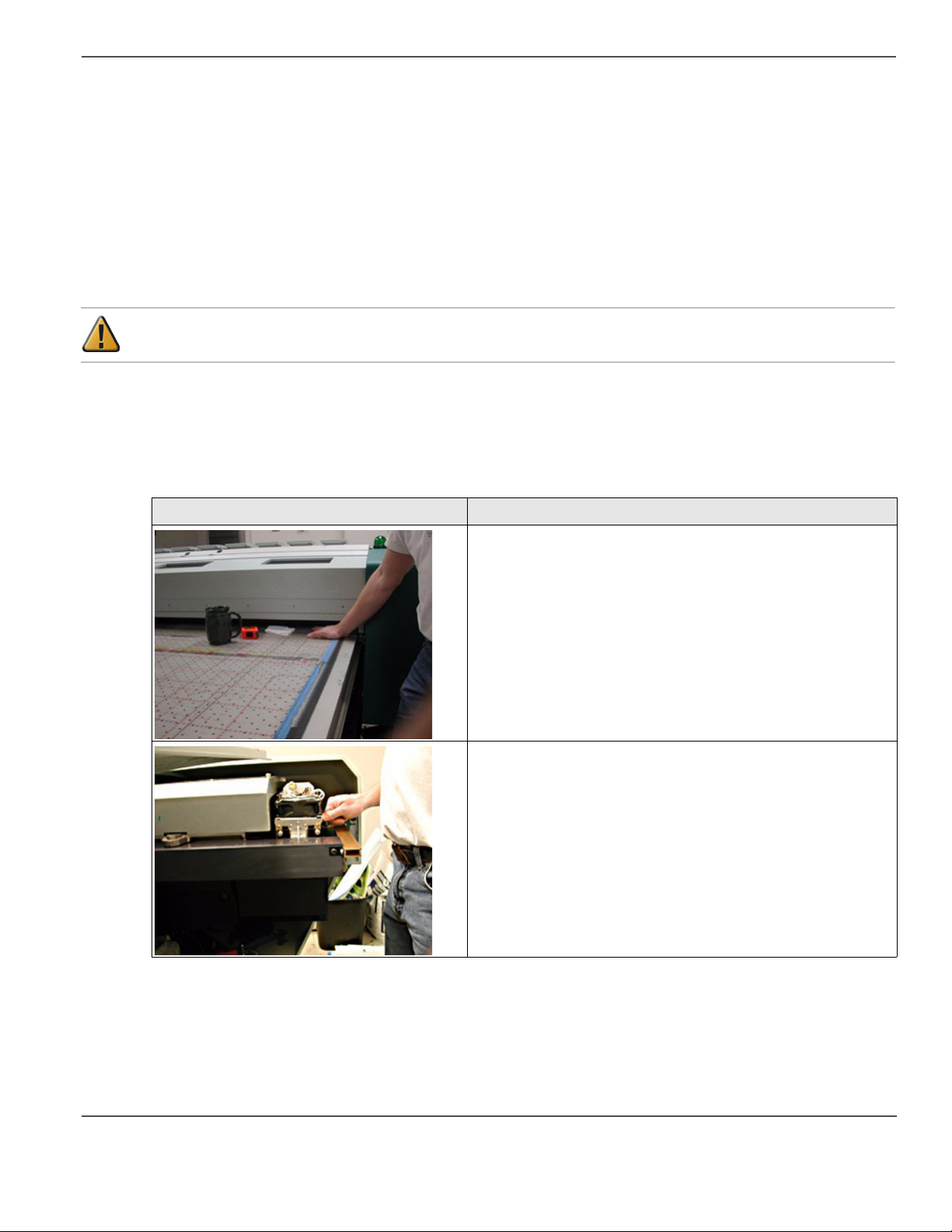
[15]
Do not place your hand under the gantry when the printer is
powered on. Do not leave any objects on the table printing
surface, except for media that you will print on. Also make sure
the media is less than 2 inches (50.8 mm) in thickness.
[16]
Do not push or force the carriage to move manually. Always use
the “Access Carriage” command in the Operator menu to move
the carriage to the blot station if you need to access the area
under the carriage.
27
Page 28
Safety Awareness
[13] How NOT to use the Arizona T220UV (2 – 2)
Avoid these Situations For Your Personal Safety
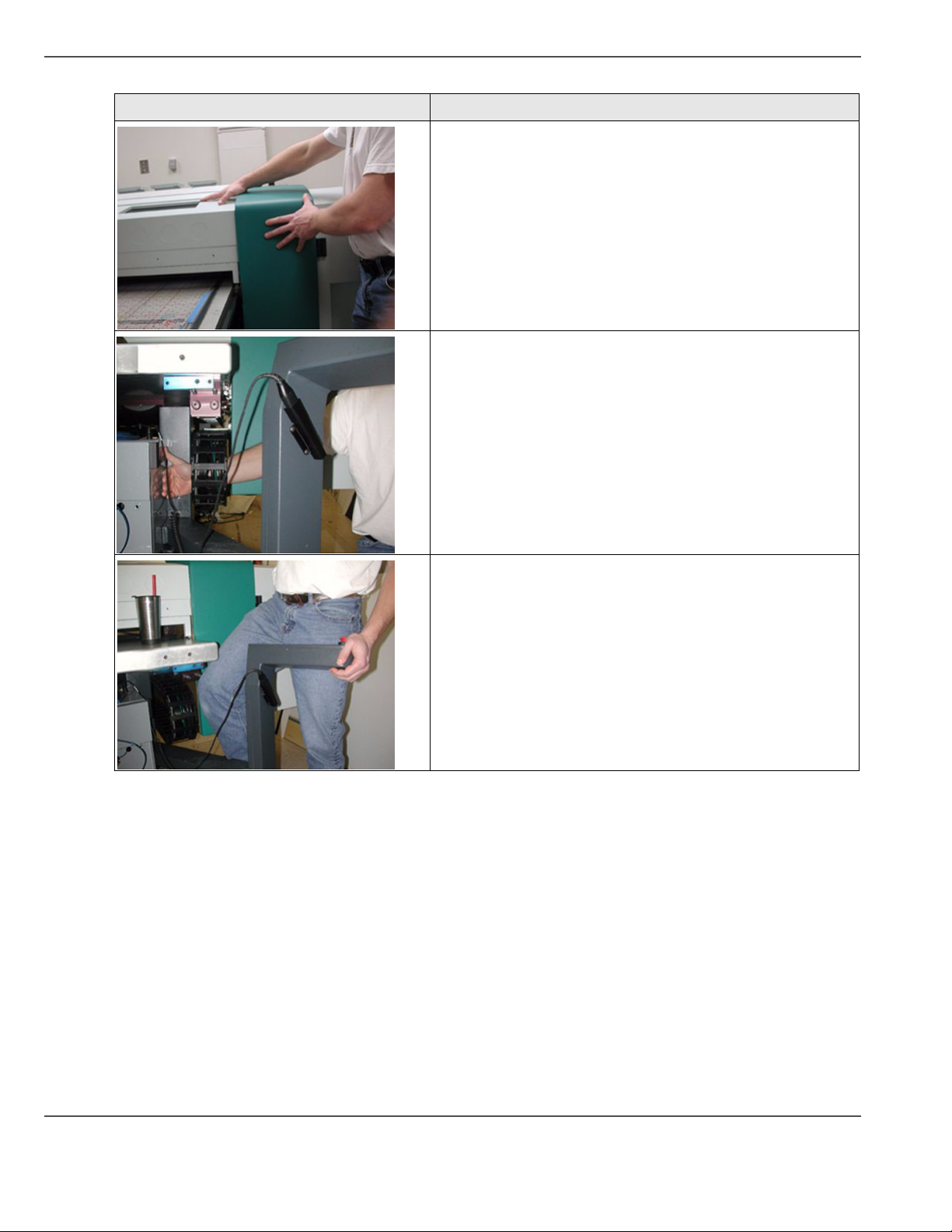
[17]
[18]
Do not push or force the gantry to move manually. Always use
the “Move Gantry” command in the Operator menu to move the
gantry along the table surface in increments of 1 foot (305mm).
Do not place you hand or arm in the end section of the IGUS
track unless power is turned off and locked out (See “Locking
Out the Power Switch”)
[19]
Do not stand at the Control Panel or close to the table when the
gantry is actively printing.
28 Chapter 3 Safety Information
Page 29
Residual Safety Risks
The Arizona T220UV is engineered to minimize machine components and operating procedures that may
compromise operator safety. However, in order to maintain some machine operations and functionality, certain
compromises are required. The following table documents some of these residual hazards. By making the operator
aware of the potential risks, we hope to ensure maximum safety in the operation of this printer.
Note: In all of these cases, the risk is reduced by slowing down the gantry in all non-print and hazardous areas.
A hinged and interlocked gate across both sides of the Gantry also reduces the risk.
Caution: there may be a time lag between when a print job is issued and when the gantry movement actually begins.
[14]
[14] T220UV Residual Risks (1 – 4)
Safety Awareness
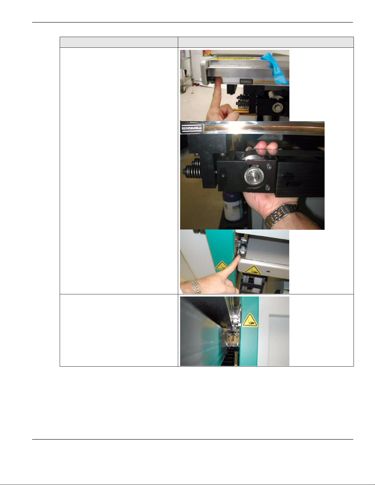
Risk Area Crushing/Shear Hazard
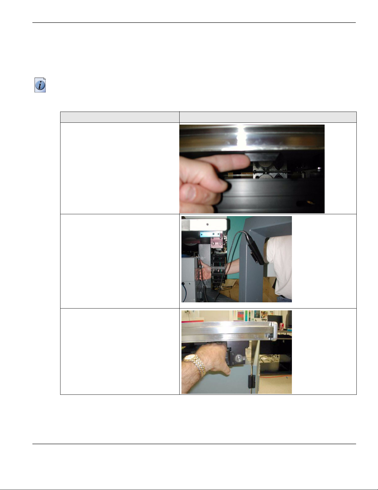
[20]
A crushing/pinch hazard is created by the
gantry and the home and away position tabs.
This is reduced by rounding off the corners
of the tab.
[21]
A crushing/pinch hazard is created by the
cable track and the frame of the machine.
A crushing/shear hazard is created by the
gantry and the frame of the machine.
[22]
29
Page 30
Safety Awareness
[14] T220UV Residual Risks (2 – 4)
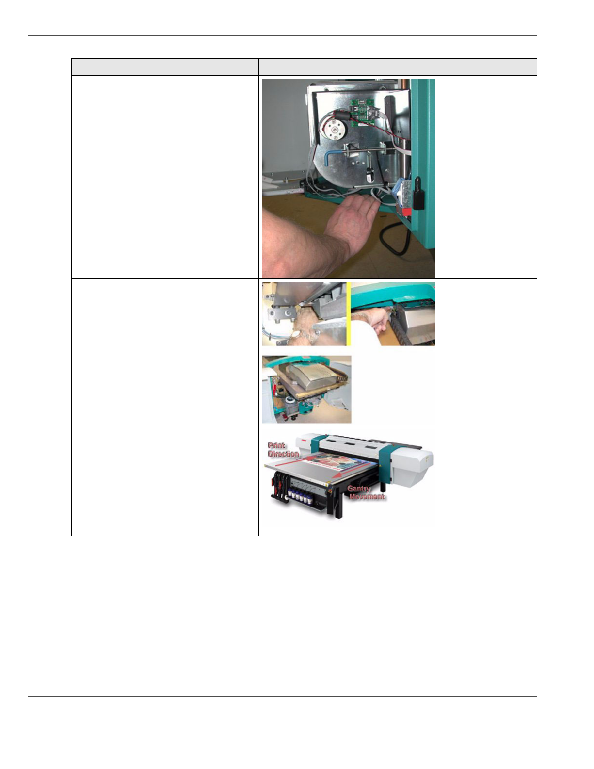
Risk Area Crushing/Shear Hazard
[23]
A crushing/shear hazard is created by the
gantry-driver cover and the gantry door of
the machine.
x
[24]
A crushing/shear hazard is created by the
gantry cable web and the frame of the
machine.
A crushing/pinch hazard is created by the
gantry cable web and the gantry.
A shearing hazard is created by the carriage
and the gantry frame from the back side
entry.
[25]
[26]
30 Chapter 3 Safety Information
Page 31
[14] T220UV Residual Risks (3 – 4)
Safety Awareness
Risk Area Crushing/Shear Hazard
[27]
[28]
A crushing/pinch hazard is created by the
gantry and the frame end at these various
positions.
A crushing/pinch hazard is created by the
gantry and the frame rails from the
underside.
[29]
[30]
31
Page 32
Safety Awareness
[14] T220UV Residual Risks (4 – 4)
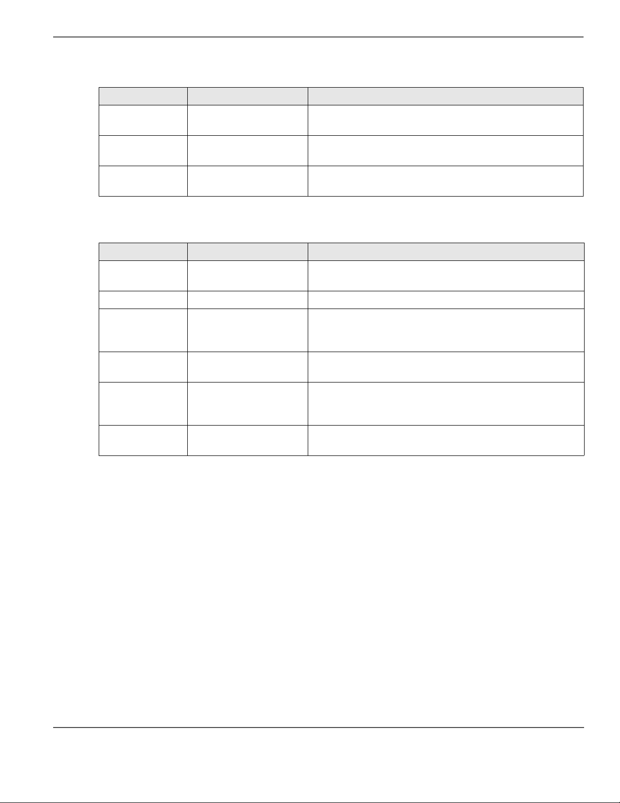
Risk Area Crushing/Shear Hazard
[31]
A crushing/pinch hazard is created by the
blotting station.
[32]
A crushing/pinch hazard is created by the
carriage assembly at these locations.
Note: the carriage assembly cannot move if
the gantry doors are open.
An impact hazard is created by the
movement of the gantry across the table
surface.
[33]
32 Chapter 3 Safety Information
Page 33

Chapter 4 User Interface
33
Page 34

Operator Control Panel
Operator Control Panel
Introduction
The control panel consists of a two line LCD display screen, a key pad, status LED’s and an emergency stop button.
A bar code wand, used for scanning ink bottle labels, is stored under the control panel. The Arizona T220UV
operator control panel provides access to the printer’s menu system.
Illustration
[34]
[35]
[34] Arizona T220UV Control Panel
[35] Key Pad, Display Screen, and Status LEDs
34 Chapter 4 User Interface
Page 35

Control Panel Keypad
The function keys on the keypad
[15]
[15] Control Panel Function Keys
Label Function
ONLINE Allows the operator to pause the printer during printing. “Online” is denoted by a solid or
CANCEL Allows the operator to cancel a print in Progress. Allows the operator to exit lower menus
MENU Allows access to the main menu.
BACK Allows you to move back to the previous menu Selection.
-+ Allows changes in menu selection. Allows increase or decrease in numerical values.
ACCEPT Allows operator to confirm menu selection.
VACUUM Allows operator to turn on vacuum supply to the table in order to hold media in place.
Status Lights
The status lights on the control panel have the following fuctions.
Operator Control Panel
flashing green status LED. Allows the operator to exit lower menus and return to the top
level menu.
and return to the top level menu.
[16]
[16] Control Panel Status Lights
Label Function
ERROR Indicates a printer problem has occured
CHECK Flashes in conjunction with operator alert messages (for example, Blotting cloth low or
INK Indicates a low ink level condition. Display will indicate which color ink to replace with a
Control Panel Display
The operator control panel displays the online screen whenever it is not displaying the menu system or presenting
error messages. If you are in the menu system and you press the ONLINE button, the panel displays the online
screen thus confirming you are no longer in the menu system.
The top left corner indicates the current status of the UV lamps. When the lamps are activated the display shows
the percentage of power achieved with an estimate of the time needed to reach operating (curing) temperature.
When the lamps are hot enough the display shows Lamp 100% and printing can begin. After a print is completed,
or if the lamps are turned off in the menu, the display shows "Cooling".
The top right corner of the online screen alternates between displaying the UV lamp temperature (when the lamps
are on) and the status of the vacuum system (either ON or OFF).
empty).
new bottle.
35
Page 36

Operator Control Panel
Gantry Beacon (BG Model Only)
Whenever the gantry is preparing to move, the green warning beacon located on the top right end of the gantry
illuminates to alert the operator. This is a safety feature that is meant to let the operator know that the table must
be clear of all objects except the media that will be printed on and also to stay clear of the gantry path when it does
begin printing.
Reset Button (BG Model Only)
This blue button on the control panel next to the red Emergency Stop button resets the printer after an interlock is
triggered by an open door. It also resets the printer after the Emergency Stop button is pushed. This is for the BG
version only. The regular T220UV printer uses the ACCEPT key to perform a system reset.
Safety Interlocks
The Interlock system is a safety shutdown feature that includes the Emergency Stop button and a system that detects
when the gantry doors are open. Interlock ensures that the gantry doors are not opened except during approved
printing or maintenance procedures. At all other times, opening the gantry doors results in a error message on the
operator display panel and a shutdown of the printer’s electrical system. A reboot is required to recover from an
interlock situation.
Note: Opening gantry doors — other than when authorized by the operator control panel display — or pushing the
Emergency Stop, results in a complete shutdown of the printer’s operating system. The only recovery soluton is a
printer reboot.
Emergency Stop
If a situation requires an immediate shutdown of all printer activity, press one of the three Emergency Stop buttons.
To recover from an emergency shutdown, resolve the problem that prompted the shutdown and then release the
Emergency Stop by twisting it slightly clockwise. Then press the ACCEPT button to restart the printer.
Note: There are three Emergency Stops, one on the control panel and one on each end of the gantry. When you
need an immediate shutdown, it is also possible to open the one of the gantry doors to initiate an interlock
shutdown.
Anytime an Emergency Stop is pressed, the lamps, the 48-volt (carriage and gantry motion) and the 24-volt (all
other motors) lines are disabled, effectively stopping all printer activity.
Note: For safety, lamp power is always disabled when a door is open. Printing is not possible with lamps off (doors
open).
36 Chapter 4 User Interface
Page 37
The following table shows what happens when the Emergency Stop is pressed.
[17]
[17] Results of a Emergency Stop
When Then Message
When system idle Requires a reboot. "E-STOP/INTERLOCK OPEN"
"check and press ACCEPT to restart"
During Print All stop, requires a reboot "E-STOP/INTERLOCK OPEN"
"check and press ACCEPT to restart"
Any other motion All stop, requires a reboot "E-STOP/INTERLOCK OPEN"
"check and press ACCEPT to restart"
When a door is opened (interlock triggered) - UV lamps are always turned off:
[18]
[18] Doors Opened During Normal Operation
When Then Message
During boot up Intervention required. "Close All Doors"
"and press ACCEPT key"
When system idle Nothing. "DOOR IS OPEN"
Operator Control Panel
Start up print
gantry movement
Gantry stopped,
intervention required.
During print All stop, intervention
required.
End of print gantry
movement
Access carriage
from menus
Gantry stopped,
intervention required.
Access/Park occurs only
if doors closed.
"SYSTEM ERROR
[press ACCEPT to restart]"
"GANTRY MOTOR or ENCODER"
"Door open while printing"
"close all doors and press ACCEPT"
"SYSTEM ERROR
[press ACCEPT to restart]"
"GANTRY MOTOR or ENCODER"
"Close All Doors"
"and press ACCEPT key"
37
Page 38

Operator Control Panel
Arizona T220UV Lamp Control
The UV lamps are necessary for drying the ink. When the lamps are on it is essential to follow the safety precautions
indicated in “UV Safety” on page 9, since the UV light is potentially harmful if safety protocol is not followed.
This section explains the different states of the lamps and how they relate to the operation of the printer.
[19]
[19] UV Lamp States
Stage Description
Lamp off When the printer is idle, the carriage is parked, and the lamp is inactive, the status of the lamp
will be displayed as "Off".
Lamp cooling When the lamp is off, but has been used recently, the lamp will go into a "cooling" state
waiting for the illuminator sensors to drop below 31C (88F).
Lamp warmup When a print is requested and the lamp is currently off, the lamp will strike and go into a
"warmup" state.
Lamp power XX% When the lamp is running, the target "power" will display in percent.
Start of a print: Once the lamps are struck, it generally takes about 2 minutes in a warm up state for the lamps to
reach their target power level. When the lamps attain their target power level, the print will not begin until the
illuminator temperature reaches 125C (257F). There is a 7-minute warm up time-out, which will cause the print to
abort and give an error message.
If the lamps begin at their idle power level and are set to go to their print power level, this change only takes a few
seconds.
After a print: When the carriage is parked, the lamps will go into an idle power mode currently defaulted to 30%.
The lamps will remain at this power level until the idle timeout occurs, currently defaulted to 10 minutes. Both of
these settings are menu adjustable. After the time-out period, the lamps will be turned off.
38 Chapter 4 User Interface
Page 39

Menu Structure
Introduction
There are three main menus accessed by pressing the MENU key pad. Once you have entered the menu system,
press the MENU key to advance the display to the next menu option. Press the ACCEPT key to access a menu’s
displayed option.
Print Queue
■ Print Jobs
Operator
■ Maintenance
■ Test Prints
■ Special Prints
■ Print Parameters
■ Delete Files
■ Units, Set Clock
■ About Printer
Menu Structure
Configure I/O
■ SCSI Port
■ Parallel Port
■ Serial Port
The Operator and Configure I/O menus have various submenus as indicated above. This section will provide
specific details of those submenus. The Print Queue has no submenus, but does provide various menu options to
modify a print job after it is selected. A detailed map of the whole menu structure is available in the Special
Prints/Menu Tree Print submenu. Refer to Appendix A for instructions to locate and print this map.
Print Queue Menu
The Print Queue menu allows the operator to select a job for printing from all jobs stored on the printer’s hard drive.
Print jobs are prepared using Onyx PosterShop software and then transferred to the printer, where they appear in
the Print Queue. The Print Queue menu provides the option to change the media thickness, image horizontal and
vertical offsets, if desired. It also offers the option to change Print Parameters such as number of copies and number
of overprints, but only if these parameters are activated in the Operator menu (see “Print Parameters” ). The details
of these Print Queue options are provided in the section “Select a Print Job” .
39
Page 40

Menu Structure
Operator Menu
The Operator menu has six submenus: Maintenance, Test Prints, Print Parameters, Units, Set Clock, and About
Printer. The details of these submenus and how to access them are provided below.
Maintenance Menu: The Maintenance Menu consists of various commands that support maintenance activities for
the printer. The commands are explained in the table below.
[20]
[20] Maintenance Menu (1 – 2)
Menu Title Function
TURN ON/OFF
UV LIGHTS
Turn the UV lights ON if you want them to start warming up before you start a print job.
This reduces the wait time between issuing a print job and the time it actually starts. Turn
the UV lights OFF if you know that you will not issue more print jobs (for example, at the
end of the day). This speed up the process of cooling down the lamps.
HIGH PURGE
NOZZLES
LONG PURGE
NOZZLES
RECOVERY
PURGE
This is used to clear contaminants out of the nozzles. Contaminants can be either
environmental particles or dried ink.
This is used primarily to clear the printheads. It lasts longer but has less force than a high
purge
This command is used as a troubleshooting tool to restore a printhead that will not respond
to a high or long purge.
NOZZLES
BLOT HEADS Blotting heads is the process of pressing the print heads into an absorbent cloth. This is
necessary to remove any ink which may have accumulated on the print head nozzle plates.
SPIT HEADS This command is used to evaluate the condition of the printheads. When it is initiated the
carriage moves to the blotting station. All printheads then fire into the blot cloth. The
carriage then returns to its previous state of operation. The operator can then observe the ink
patterns created on the blot cloth from the spit. If the patterns are not forming clean lines of
equal length, it can be an indication of blocked nozzles.
FILL
RESERVOIR
This command manually fills one or more ink reservoir with ink. This is generally only used
if ink-fill is turned Off and the user wants to manually ensure that the ink reservoirs are full
of ink. The system stops the filling when the ink reservoir level sensor indicates that the ink
reservoir is full.
MOVE GANTRY Allows you to place the gantry at any location over the table in increments of 1 foot (30.5
ACCESS
CARRIAGE
PA RK
CARRIAGE
RAISE
CARRIAGE
BLOT CLOTH
DISPLAY
40 Chapter 4 User Interface
cm).
This command raises the carriage to the currently-set media height and moves the carriage
over to the blotting station. This is useful to gain access to the underside of the carriage in
order to manually clean the print heads.
This command moves the carriage to the capping station and lowers the carriage onto the
foam pads (called 'capping'). It is necessary to perform this step any time the operator has
been doing manual maintenance and wishes to park and cap the carriage.
This command raises the carriage to currently-set media height then moves the heads over
the drain, which allows the carriage to be moved manually for service access.
Allows you to determine when to start displaying the Blot Cloth Low message based on the
percentage of blot cloth remaining.
Page 41

Menu Structure
[20] Maintenance Menu (2 – 2)
Menu Title Function
LAMP USAGE Allows you to check both UV lamps for the total number of strikes and the length of time
the lamps were on so that you can monitor usage over time. It also allows you to reset the
usage statistics when you replace a lamp.
BARCODE
PRACTICE
Allows you to practice scanning barcodes without using new bottles of ink so you can get a
feel for the barcode wand. Practice barcodes can also be entered manually using the keypad
(See “Scanning Ink Barcodes” on page xx).
Test Prints Menu - The Test Prints menu allows you the option of printing three documents stored in the Arizona
T220UV printer:
• Nozzle print (Diagnostic and Standard)
• Configuration print
• Color bars print
In the nozzle prints, breaks in the line indicate which heads are misfiring. Performing a High Purge or Recovery
Purge on the ink colors that show misfiring can help to clear the affected heads. For a more detailed explanation of
how to use the nozzle print for diagnostic purposes, refer to (see ‘How to Reduce Banding’ on page 57).
[21]
[21] Test Prints Menu
Component Function
NOZZLE PRINT The Nozzle Print menu provides you with a visual representation of how the print heads are
firing.
COLOR BAR The Color Bars menu prints a set of color bars. The eleven color bars start with Light
Magenta and end with Black.
CONFIGURATIO
N PRINT
The Configuration Print menu provides the operator and Océ Display Graphics Systems
service technicians with machine-settings data if the unit must be diagnosed or recalibrated.
A current configuration print for your printer should be stored for reference.
41
Page 42

Menu Structure
Special Prints Menu - The Special Prints menu gives you access to the Menu Tree print and the Table Grid print,
either metric or imperial version.
[22]
[22] Special Prints Menu
Component Function
Menu Tree Print The Print Menu Tree menu generates a print which is a graphical illustration of the
Grid Print The Table Grid is used to position media for printing. It is printed directly on the printer
T220UVsystem menu tree. This 32 x 56 inch poster illustrates the Operator, Print Queue,
and Configuration menu thus providing you with an overview of the menu system. It also
contains Safety Guidelines, a summary of the Maintenance Schedule, and Application Tips.
If the print does not show up in the Special prints menu, or of you want to check for an
updated version, the Menu Tree Print must be downloaded from the ODGS web site and then
copied to the printer. For detailed instructions, see Appendix A.
table. This ensures that printed production jobs are registered with exact pixel placement. If
necessary, the grid can be cleaned off the table and reprinted. The grid file comes in two
versions: metric and imperial units.
Either the Imperial and Metric grids appear as a menu selection - Operator / Special Prints.
Which one appears depends on what was loaded (see below). Before printing the grid, make
sure that you set the height to 0 (zero) and also when the display prompts to set the pre-fire
strip catcher height, remove any media or other spacing material from the slot in the catcher.
If the Grid does not appear as a menu option, it must be downloaded from the ODGS web
site and then copied to the printer. For detailed instructions, see Appendix A.
Print Parameters Menu
The Print Parameters menu lets you set Enable Job Parameter Changes. If this is set to ON, you can decide which
of the following options are presented to the operator prior to printing (See “Print Job Parameter Options” on page
32):
■ BiDirectional Printing - either in both directions or just right to left
■ # of Copies - print up to 100 copies of an image
■ # of Overprints - prints the image on the media up to 3 times.
Ink Menu
The Ink Menu lets you view approximately how much ink is left in each bottle and also to install new ink bottles,
if required.
42 Chapter 4 User Interface
Page 43

Menu Structure
Delete Files
The printer’s hard drive has a capacity of 70 gigabytes for storing print jobs. When the drive is full, the oldest file
is automatically removed to make more space available. The Delete Files menu lets you delete all print job files
stored on the drive. It is not possible to select particular files for deletion - using this option deletes all files (print
jobs) on the drive.
Units Menu
The Units menu allows you to choose between Imperial (English) and Metric units. All control panel menus display
the preferred units. The Units menu is part of the Operator submenu.
Set Clock Menu
The Set Clock menu allows you to set the date and time. When the date and time are set, they are printed in the
statistics output.
About Printer Menu
Displays amount of media printed, firmware revision, firmware build date, firmware build time, serial number, and
boot ROM version. The About Printer menu allows you to view the current printer specifications on the printer
control panel. The same information is available in the configuration print.
Configure I/O Menu
The Arizona T220UV printer can accept input through two types of ports, Centronics parallel, and low-voltage
differential (LVD) SCSI-2 communication ports. They are built into the printer. The Active menu allows you to
select the type of port - Parallel or SCSI.
Parallel Port
The printer uses a standard Centronics-type parallel data cable to allow access for service and diagnostic purposes.
LVD-SCSI-2 Port Configuration
Océ Display Graphics Systems recommends that you use the Adaptec 29160 68- pin LVD-SCSI-2 card in the
computer that connects to the T220UV printer. The printer ships with a standard 32 foot (10 meter) 68-pin SCSI-2
data cable. It uses the ultra SCSI settings under this menu to support/enhance the transfer speed of your computer
platform when printing to the Arizona T220 printer.
Note: NEVER connect or disconnect SCSI cables with the printer powered On. Disconnecting powered
connections can make printer hard drives unusable.
If you have any error messages on the computer or printer display pertaining to the SCSI port, or if print jobs are
not transferred to the Print Queue, check that the SCSSI settings are exactly as indicated here:
Active: SCSI
SCSI Address: 5
Timeout: 60 seconds
Ultra SCSI: ON
Interface Cable: LVD
43
Page 44

Menu Structure
44 Chapter 4 User Interface
Page 45

Chapter 5 How to Operate the Arizona T220UV
45
Page 46

Training Requirements
Training Requirements
Introduction
Before operating the Arizona T220UV printer, make sure you have read and understood the section “Safety
Guidelines”.
Océ Operator Training
For optimal safety and print quality, the Arizona T220UV printer operator must be trained by a qualified Océ
service personnel. Océ training provides a general orientation to the Arizona T220UV printer safety and operating
procedures. This training involves both the User and Maintenance Training modules.
PosterShop Training
Maximum performance from the Arizona T220UV printer requires a properly trained operator. Océ Service and
Support Group trains the operator in the use of the Arizona T220UV hardware and software at installation.
However, this is not a substitute for formal PosterShop® training.
Operators of the Arizona T220UV should be fully versed in the operation of Onyx PosterShop® . For any operator
unfamiliar with its operation, Onyx PosterShop® training is required. On-site or off-site training courses are
available; contact Onyx Graphics Corporation for more information: Visit
http://www.onyxgfx.com/support_training.html
46 Chapter 5 How to Operate the Arizona T220UV
Page 47
How to Switch the Printer On
Introduction
You must switch on both the Arizona T220UV printer and the Postershop computer before you can print. This
section describes how to switch the printer on. Refer to the Onyx Postershop documentation for information on how
to install and run the Postershop computer.
Before you begin
Before you apply AC power to the printer, make sure that loose objects such as clothing, tools and cleaning
materials are not interfering with the printer mechanisms. Position the power cord so that it does not pose a hazard
when walking around or accessing the doors on the printer. The Arizona T220UV has an AC power circuit breaker
that functions as an On/Off switch, and it has an AC power lock-out switch, (it also has an AC power plug, referred
to as the Disconnect Device - see below). All of these power-related items are located on the blot station side of
the electronics enclosure.
Caution: THE SOCKET OUTLET MUST BE INSTALLED NEAR THE EQUIPMENT AND BE
EASILY ACCESSIBLE. Ensure that you follow the guidelines in the Arizona T220UV Site Preparation
document before plugging the printer AC power plug into the socket.
How to Switch the Printer On
Attention: Unplugging the power cord from the wall socket is the only way to isolate the entire machine.
47
Page 48

How to Switch the Printer On
Illustration
[23]
1 - Lockout Device 2 - On/Off Switch 3 - AC Power (Disconnect Device)
[36]
4 - SCSI Connector 5 - Parallel Cable 6 - Serial Cable
[36] AC Power, Connections & Disconnect Device
To Power ON
1. Ensure the red AC power plug is properly seated; and
2. Turn on the AC power circuit breaker On/Off switch.
Attention: After powering the printer On, leave it running continuously, even when at idle, because the printer
automatically runs maintenance routines to keep it at its optimum operating specifications. Failure to leave the
printer powered on may result in ink draining out of the ink reservoirs.
48 Chapter 5 How to Operate the Arizona T220UV
Page 49

How to Lock Out the Power Switch
Attention: Some maintenance and service procedures require locking out the On/Off switch to ensure
operator safety. When the switch is locked out it is impossible to supply power to the printer.
1. Turn the Lock-out switch to the Off position.
2. Apply a lock and a tag-out label to the switch for the duration of any service or maintenance procedures.
Illustration
[24]
1 - Lock-Out / Tag-Out Device with Lock
[37]
How to Switch the Printer On
2 - Circuit Breaker On/Off Switch
[37] Lock-Out / Tag-Out and AC Power Switch
49
Page 50

How to Switch the Printer On
Disconnect Device
Attention: The red AC power plug is the disconnect device for the Arizona T220UV printer. For maximum
safety, if the printer is moved or if any service or repair work is conducted, the disconnect device must first be
unplugged from the printer.
1. To unplug it, first press down on the release flange with your thumb.
[38]
2. This flips up the safety cover and allows you to pull the disconnect device out of its socket.
[38] Unplugging the Disconnect Device
Note: the vacuum pump, which is separate from the printer, also uses a disconnect device that looks and functions
in a manner identical to the one on the printer.
50 Chapter 5 How to Operate the Arizona T220UV
Page 51

How to Set Up a Print Job
Select a Print Job
Introduction
The section explains how to select an image to print on the Arizona T220UV.
Note: The image for the print job must first be sent to the printer using Onyx Postershop to prepare a digital image
for printing.
Attention: Do not print on mirrors or any other highly reflective media as UV light is reflected off such
media. This results in curing the ink in the heads and thus damaging them.
Choose the Print Job
1. Press the MENU button on the control panel to enter the menu system. The Print Queue menu is always the first
main menu option.
2. Press ACCEPT to enter the Print Queue menu. The LCD panel displays the most recent job sent to the print queue
by the host computer (i.e., PosterShop).
You have four possible choices:
■ Press CANCEL to quit viewing the print queue and proceed to the next main menu option which is the Operator
menu.
■ Press MENU or BACK to return to the Print Queue menu.
■ Press the + or - keys to cycle through all avaliable print jobs.
■ Press ACCEPT to confirm that you want to proceed with the print job that is currently displayed.
Select a Print Job
3. Press ACCEPT and the control panel display shows the following information for the selected print job.
Note: Thickness and offsets values are retained from the previous time these values were entered. Ensure that they
are appropriate to the current media and print job. If not, use the method described below to change them.
Print the Print Job
1. Press ACCEPT to continue the print job.
When you press ACCEPT, the display advances to the Place Media menu, the last step prior to actual printing.
Change the Job Settings
1. Alternately, press the + or - key if you want to change media thickness, UV power, horizontal or vertical image
offsets, or print job parameters (if Parameters is enabled).
When you press + or - keys, the display advances to the New Media Thickness display, as indicated in the next
section.
51
Page 52

Change Print Job Settings
Change Print Job Settings
Introduction
The following three settings may be altered only if the operator chooses to change them when the print information
for a particular job is displayed by pressing the + or - keys:
• Media Thickness
• UV Power Setting
• Horizontal and Vertical Offsets
Purpose
If you pressed + or - when the print job information was displayed, you can change settings in the print job.
When to do
The desired media thickness is first set when you prepare the image in PosterShop and then verified at the control
panel prior to printing. As a precaution against damaging the printheads, there is a media touch rotary switch
located on the lead edge of the carriage used to detect any obstacles higher than the media on the table. If anything
on the table is sitting too high, including the media, the media touch rotary switch will cause the gantry to stop and
the control panel will alert the operator of the problem.
Note: Do not rely on media thickness specifications listed on the media supply box. Always measure the media
with a digital caliper (see below) to be sure of the correct height.
In the second menu display you can change the power setting of the UV lamps. A higher setting results in faster
drying of the ink but also applies more heat to the media.
The third menu display allows you to change first the horizontal and then the vertical offsets. This determines where
the image is printed on the media.
Required tool
ODGS recommends that the operator measure the media thickness with a set of calipers.This ensures optimum
conditions for achieving the best possible print quality by placing the print nozzles at the optimal height above the
media. Since the clearance between the media and the print heads is only 2mm (0.08 in.), altering the clearance has
a negative impact on the bi-directional alignment.
52 Chapter 5 How to Operate the Arizona T220UV
Page 53

Change Media Thickness
1. Use the ACCEPT key to move through the displayed digits. The selected digit has an underline indicating it can
be increased or decreased using the + or - keys.
2. When the digit you want is displayed, press ACCEPT and the underline moves to the next digit.
3. When you are at the last digit, pressing ACCEPT advances to the Offests menu.
Note: Use the MENU key to move to the next digit if no changes are required for a particular field.
Change UV Power Setting
1. Use the ACCEPT key to move through the displayed digits. The selected digit has an underline indicating it can
be increased or decreased using the + or - keys.
2. When the digit you want to use is displayed, press ACCEPT and the underline moves to the next digit.
3. When you are at the last digit, pressing ACCEPT advances to the Place Media display if Print Parameters were
NOT enabled in the Operator/Print Parameters menu.
Note: If Display Print Parameters is set to OFF in the Operator/Print Parameters/ Statistics menu, the control
panel display shows the message “Place media on the table” and the print job can begin.
Change Print Job Parameter Options
Change Horizontal and Vertical Offsets
1. Use the ACCEPT key to move through the displayed digits. The selected digit has an underline indicating it can
be increased or decreased using the + or - keys.
2. When the digit you want to use is displayed, press ACCEPT and the underline moves to the next digit.
3. When you are at the last digit, pressing ACCEPT advances to the Place Media display if Print Parameters were
NOT enabled in the Operator/Print Parameters menu.
Note: If Display Print Parameters is set to OFF in the Operator/Print Parameters/ Statistics menu, the control
panel display shows the message “Place media on the table” and the print job can begin.
Change Print Job Parameter Options
Introduction
The print job parameter options consist of three functions that support printing. If a particular option was enabled
in the Operator\Enable Job Parameters Change menu, and if the operator decides to change the settings of a selected
print job, then its associated screen is displayed in the following order.
■ BiDirectional Printing - either in both directions or just right to left
■ # of Copies - print up to 100 copies of an image
■ # of Overprints - prints the image on the media up to 3 times
53
Page 54

Change Print Job Parameter Options
Purpose
The Operator\Print Parameters menu lets you set Enable Job Parameter Changes to ON or OFF. If this is set to ON,
you can decide which of the three options are presented to the operator prior to printing. If this is set to OFF, then
the options will not appear in the display when the operator chooses to change the other settings in a selected print
job.
Note: Use the MENU key to move to the next option if no changes are required for a particular parameter.
Change Print Direction
1. Press + or - to change the printing direction. Options are Single or Bidirectional — single means that the nozzles
will print only in the right to left direction, while bidirectional prints in both directions.
2. Press ACCEPT when the printing option you want is displayed.
Change Number of Copies
1. Press + or - to change the number of copies printed. Options are 1 to 100. Use the ACCEPT key to move through
the displayed digits. The selected digit has an underline indicating it can be increased or decreased using the + or
- keys.
2. When the digit you want is displayed, press ACCEPT and the underline moves to the next digit.
3. When you are at the last digit, press ACCEPT to choose the number of copies that is displayed. The display will
advance to the Overprints display (if enabled).
Change Overprints
1. Press + or - to change the number of times the image prints on top of itself. Options are 1 to 3. Use the ACCEPT
key to move through the displayed digits. The selected digit has an underline indicating it can be increased or
decreased using the + or - keys.
2. When the digit you want is displayed, press ACCEPT and the underline moves to the next digit.
3. When you are at the last digit, press ACCEPT to choose the number of overprints. The display advances to the Place
Media menu.
Place Media Menu
1. Press the VACUUM button on the control panel to turn on the vacuum system that holds the media in place for
printing.
2. Press ACCEPT and the gantry will move to position itself over the media.
Note: Printing may not start immediately as the UV lamps must warm up to print temperature so that they can cure
the UV-based ink used for imaging on the media.
When printing begins, the image start point is the lower left corner of the image.
54 Chapter 5 How to Operate the Arizona T220UV
Page 55

How to Use the Media Vacuum
The Media Vacuum System
Introduction
The vacuum table is a thin hollow rectangular aluminum box with aluminum box extrusions forming a perimeter
frame, two 1/8" aluminum skins forming the top and bottom surfaces, and aluminum honeycomb in the interior
supporting the skins. The top surface is drilled with 1mm diameter vacuum holes with a 5mm diameter counterbore
to allow air flow into the table and create a vacuum hold-down for the media.
There are four zones on the table platen. Each zone is 32” (81cm) x 62” (158cm). The first zone is always available
while the other three must be selected by the operator.
Purpose
The vacuum table platen holds the media in place during printing, if the vacuum is activated.
When to do
When you finish selection of all print parameters, the operator control panel displays a reminder to turn on the
vacuum system before you begin the print job.
The Media Vacuum System
Note: The position of the individual control handles determines whether zones 2, 3, or 4 are activated when the
vacuum system is on.
Illustration
[39]
[39] Location of Vacuum Zones
55
Page 56

The Media Vacuum System
How to Activate All Four Vacuum Zones
1. Turn on the vacuum pump by pressing the VACUUM button on the control panel. This causes any media placed
over Zone 1 to be held in place by the ensuing suction.
2. Activate Zone 2 by turning the right control handle counter-clockwise 90 degrees.
3. Activate Zone 3 by turning the center control handle counter-clockwise 90 degrees.
4. Activate Zone 4 by turning the left control handle counter-clockwise 90 degrees.
5. Press the Vacuum button on the control panel again to turn off the vacuum pump.
Note: Note that the location of the zones is also indicated on the table grid. See Appendix A for instructions on
how to print the grid onto the table.
56 Chapter 5 How to Operate the Arizona T220UV
Page 57

How to Maintain Print Quality
How to Reduce Banding
Introduction
Banding can occur in an image for a number of reasons. Typically it occurs due to neighbouring nozzles not firing
or nozzles firing with poor directionality. This will occur if debris has been picked up from the media or table by
a printhead. If this happens, closely inspect the underside of the carriage with a flashlight and remove any debris
with a foam-tipped swab.
Note: Keep the table surface clean and ensure the media is clean and dust free to help reduce banding.
Purpose
Print quality is increased when banding is reduced.
The Diagnostic Stripe and Nozzle prints are tools that help you to detect banding that results from nozzle dropout
and poor directionality:
How to Reduce Banding
Diagnostic Stripe
When activated, the stripe is printed along the edge of a print job. Use the Diagnostic Stripe to help quickly pinpoint
the cause of any banding.
Nozzle Prints
The Standard and Diagnostic Nozzle prints provides you with more detailed visual information about nozzle
dropout or poor directionality from your print heads.
Recommendations to Reduce Banding
Caution: Severe banding may be caused by the blot cloth running out. Also, DO NOT re-use a blot cloth
as this could scratch the print heads as well as cause banding.
1. Keep the printer clean.
2. Store the media in a warm and dry environment.
3. Take care when loading the blot cloth, otherwise tracking will be affected and the cloth will not advance. A good
blot is essential for reliable print quality.
4. After opening the carriage cover, always check that the tubes exiting the bottom of the ink reservoirs are clipped
to the side of the ink reservoir, otherwise the acceleration of the carriage may affect the performance of the heads.
57
Page 58

Diagnostic Stripe
Diagnostic Stripe
Introduction
The Diagnostic Stripe is an option that can be turned on or off in the Print Parameter menu. If the option is turned
on, then on the first swath of printing, a stripe is printed on the away side of the image. The stripe is printed every
time the gantry has stepped approximately 250mm. This stripe can yield a lot of detailed information similar to the
diagnostic nozzle print regarding the position and condition of the heads.
Note: Make sure the media is large enough to allow the stripe to print on the away side. Otherwise the stripe may
print on the table. Alternately, use a piece of scrap media of the same thickness to print the stripe on.
Illustration
[40]
[40] Diagnostic Stripe
58 Chapter 5 How to Operate the Arizona T220UV
Page 59

Nozzle Order
Each head has a row of 128 nozzles. The outer nozzles are not fired in the image or in the Diagnostic Stripe. Due
to the nature of the head, adjacent nozzles can’t be fired at the same time. Nozzles are labeled in the following
order:
Outer Nozzle A B C A B C ……….. A B C A B C Outer Nozzle
1 • • • • • • • • • • • • • • • • .………...• • • • • • • • • • • • • • 128
In the Diagnostic Stripe all the ‘A’ nozzles are fired first, then the ‘B’ nozzles and finally the ‘C’ nozzles. Each
nozzle is fired 16 times. Refer to "Detail from Diagnostic Stripe".
[41]
Diagnostic Stripe
[41] Detail From Diagnostic Stripe
59
Page 60
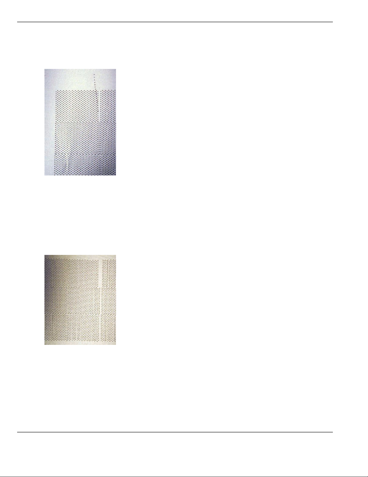
Diagnostic Stripe
"C" Nozzle with Poor Directionality
The next example (see figure 42 on page 60)shows that one of the ‘C’ nozzles in the front black head has poor
directionality. This will be seen as slight overspray in the image. This is caused by dry ink or another contaminant
in or around the nozzle. An individual nozzle dropout has little effect on image quality.
[42]
[42] Single Nozzle Not Firing
Five Adjacent Nozzles Not Firing
The next example (see figure 43) illustrates 5 adjacent black nozzles not firing at all. This introduces banding in an
image. It is caused by dry ink or other contaminants in or around the nozzle. This is fixed by cleaning the head with
a swab and UV Flush, then performing a High Purge on the individual color. If necessary, follow this by swabbing
the affected head and finally by syringing the affected head until the ‘curtain’ of UV Flush exiting the head is
continuous – no gaps or spray in the wrong direction.
[43]
[43] Five Adjacent Nozzles Not Firing
60 Chapter 5 How to Operate the Arizona T220UV
Page 61
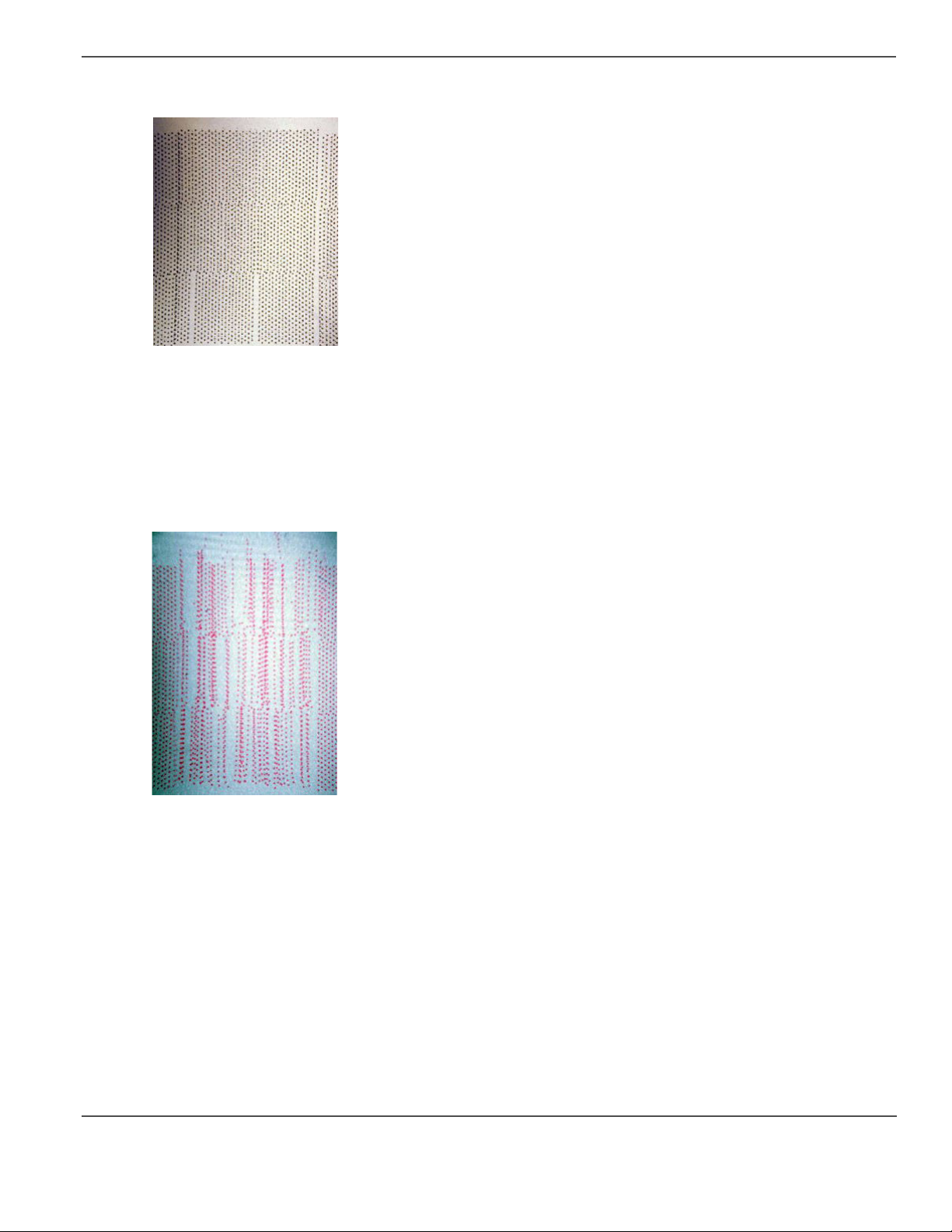
Poor Head Position
[44]
[44] Black Head Poorly Positioned
The previous example (see figure 44) shows that the black head is poorly positioned in the inner carriage. The head
is overlapping with its neighbor on the left and there is a gap between it and the head on the right. Also there appears
to be a delay before the head fires relative to its neighboring heads, which would indicate that the head is not pushed
down fully in its mounting hole.
There are also 2 nozzles out. As they are not next to each other this should not introduce an artifact in the image
and they will probably recover on their own either during the image or during the pre/post print automated
maintenance. If the nozzles do not recover then further maintenance will be required (see below).
Diagnostic Stripe
[45]
[45] Poorly Operating Magenta Head
The final figure shows an example of a magenta head that is operating poorly. There are nozzles out and nozzles
with poor directionality causing overspray. There will definitely be banding visible in any parts of the image where
magenta is used. A dirty head, ink pooling on the nozzle plate, or ink curing around the nozzles, can cause this
banding.
A High Purge on the individual color may fix this - if not, try a Recovery Purge. If necessary follow this by
swabbing the affected head.
If left untreated the overspray from this head may cause similar problems with other heads nearby.
61
Page 62

Standard Nozzle Print
Standard Nozzle Print
Introduction
There are two types of nozzle prints: Standard and Diagnostic. Both are found in the Operator/Test Prints menu.
The Standard nozzle print provides you with visual information about nozzle dropout or poor directionality from
your print heads. The circled areas in the sample Standard Nozzle print below indicate the dropouts than can result
from plugged or misfiring nozzles.
Purpose
The Standard Nozzle print gives you a visual indication of nozzle dropout and poor directionality in print heads. In
particular, it is very helpful when a block of nozzles on the outside (i.e., the outer ends of head 1 and head 4)
becomes plugged. This situation causes banding but is hard to identify using a diagnostic stripe or a diagnostic
nozzle print.
When to do
Turn on the Diagnostic Stripe while printing to get a sense of the print head and nozzle condition and to help identify
causes of banding. However, when troubleshooting a persistent banding problem, we recommend that you print both
the Standard and Diagnostic Nozzle prints to get more detailed insight into the problem. The Standard Nozzle print
is useful for identifying plugged end nozzles and poor directionality.
62 Chapter 5 How to Operate the Arizona T220UV
Page 63

Illustration
[46]
Standard Nozzle Print
[46] Standard Nozzle Print
How to Use the Standard Nozzle Print
1. Navigate to the Operator/Test Prints menu and select the Standard option to perform a Standard Nozzle Print to
verify that all nozzles fire properly.
2. Identify any nozzles that do not fire properly and repeat the nozzle print, preferably on the same media with a slight
offset.
3. Perform a High Purge on individual colors for any nozzles that are not working in both previous tests.
4. Repeat the Nozzle Print. Perform a Recovery Purge on individual colors for any nozzles that still do not fire.
5. Repeat the Nozzle Print again. If any nozzles have not fired in all of these nozzle prints, manually flush the print
heads associated with those nozzles.
6. Repeat the Nozzle Print and replace any heads that still have nozzles that do not fire.
63
Page 64

Diagnostic Nozzle Print
Diagnostic Nozzle Print
Introduction
The Diagnostic Nozzle print illustrates the results of firing all nozzles on all of the printheads. This allows you to
evaluate any problems with nozzles or heads.
Purpose
The Diagnostic Nozzle print lets you know if the nozzles are firing properly on all of the print heads.
When to do
Turn on the Diagnostic Stripe while printing to get a general sense of the print head and nozzle condition and to help
identify causes of banding. However, when troubleshooting a persistent banding problem, we recommend that you
print both the Standard and Diagnostic Nozzle prints to get more detailed insight into the problem. The Diagnostic
Nozzle print is similar to the Diagnostic stripe but has the advantage of not overlapping heads 1 and 4 of adjacent
colors in the printed test image. Hence the Diagnostic Nozzle print is superior to the Diagnostic stripe in that it
shows all nozzles of all heads without overlap. Also, the image is repeated in the carriage direction and can be run
independent of a production image.
Note: Select multiple copies when you perform a nozzle print since this illustrates the relationship between heads
1 and 4 of adjacent colors. In the example below, three (3) copies was selected in the Nozzle Print menu.
Illustration
[47]
[47] Diagnostic Nozzle Print
64 Chapter 5 How to Operate the Arizona T220UV
Page 65

How to Use the Diagnostic Nozzle Print
1. Navigate to the Operator/Test Prints menu and select Diagnostic to perform a Nozzle Print that verifies all nozzles
are firing.
2. Select the number of copies (this means the number of times that each head repeats the test print - in the example
above, 3 copies was selected).
3. Identify any nozzles that are not working and repeat the nozzle print, preferably on the same media with a slight
offset.
4. Perform a High Purge on individual colors for any nozzles that are not working in both previous tests.
5. Repeat the Nozzle Print. Perform a Recovery Purge on individual colors for any nozzles that still do not fire.
6. Repeat Nozzle Print. If any nozzles have not fired in all of these nozzle prints, manually flush the print heads
associated with those nozzles.
7. Repeat the Nozzle Print and if any heads still have nozzles that do not fire, have them replaced.
Note: If you need to replace any heads, contact your Océ service representative.
Application Hints and Tips
Introduction
The following recommendations are based on our experience with the Arizona T220UV printer. They are offered
as staring points or suggestions for dealing with various situations.
Application Hints and Tips
Hints and Tips
[25]
[25] Hints and Tips (1 – 3)
Situation Solution
Maximum Ink Restrictions You can go right up to the maximum of 100% with 100% overstrike, if required.
Recommended Dmax Values Recommended Dmax values are approximately: C,M 1.4, Y .8, K 1.6.
Increasing Black Density Use ICC profiles. Or use color replacement to change 100%K to a rich black. 40%
Head Swabbing Frequency Monitor the diagnostic strip and swab heads if a recovery purge of the problem
Printing on uneven surfaces Use a thickness equal to the thickest value of the media, and print unidirectional.
Overprinting Techniques Overprinting may be required on some media to build up ink density - e.g., backlit
Use only enough ink to achieve sufficient Dmax and good-looking reds.
C, 30% M, 30% Y, 100 %K have given good results on a variety of media. The
maximum recommended values are 60% C, 40% M, 40% Y, 100% K.
color does not resolve the problem. The required swab frequency will be
dependent on many factors such as: printer duty cycle used, print volume, and
media/air cleanliness. In a low volume production setting, typically swab heads
about once a week.
material or glass. Hitting color and proper linearization when using overprinting
is difficult.
65
Page 66

Application Hints and Tips
[25] Hints and Tips (2 – 3)
Situation Solution
Thermal Expansion of Media Some media, such as Styrene, Fome-Cor, or plexiglass, is subject to expansion
Using a generic ICC Profile If an ICC profile is not available for a particular media and it is not
Imaging on Fome-Cor Fome-Cor has a tendency to warp when heat is applied. However it will go back
when subjected to heat. If multiple pieces of these media are used, allow enough
space between the pieces to allow for thermal expansion. Placing tape on the table
prior to laying down the media will prevent ink from being imaged onto the table.
When overprinting on media that will expand when heat is applied, we
recommend that you group the desired image with a preceding image so the
printer is a consistent temperature when starting to print the desired image. Note
that color-to-color registration may be affected if the media expands significantly
between printing the first and last colors.
possible/convenient to create one specifically for that media, determine the ink
restriction values required to achieve Dmax for that media. Then select an ICC
profile for another media that uses the same ink restriction values and has similar
dot gain characteristics and the result may be satisfactory.
to it’s original shape once cooled. Media Holder Strips (aluminium bars) with a
45 degree chamfer are available to hold down the Fome-Cor. The bars are 2” wide
and 32” long.
Imaging on Coreplast avoiding warping
When imaging on Coreplast set Full Carriage Travel to On in the
Operator/Maintenance/Print. This reduces the tendency of the media to turn warp
near the outer edges from excessive heat generated by the UV lamps. By having
it travel beyond the edge of the media during each swath there is less concentration
of heat from the UV light during the time the carriage changes direction. Also
consider lower the power level of the UV lamps. The power level must be set only
high enough to cure the ink.
Imaging on Sintra - avoiding
brown edges
When imaging on Sintra set Full Carriage Travel to On in the
Operator/Maintenance/Print. This reduces the tendency of the media to turn
brown near the outer edges from excessive exposure to UV light. By having it
travel beyond the edge of the media during each swath there is less concentration
of UV light during the time the carriage changes direction.
Avoid Printing Large White
Space Areas
Do not add white space to an image to center it on the media, instead use the center
media option in the PosterShop Layout Preview dialog to center the image.
Adding white space to the image increases the print time and may dry out the
nozzles resulting in over-spray and banding. Turning on the regular stripe on the
away side of the image, will help prevent the nozzles from over-spraying.
Imaging on a new media When imaging on a new media for the first time (i.e., you do not have a media
model for the media), we recommend that you guess at an appropriate ink
restriction level and heater duty cycle. Then print either a test image or the job to
be printed prior to doing linearization. Once reasonable ink restriction values and
heater duty cycles are selected, linearization and ICC profiling can be done, if
required.
Imaging off the media If anything is printed off the media (e.g., diagnostic stipe or a bleed) use a
sacrificial scrap piece of media - either the same height or up to 1 mm less. Failing
to do so causes ink to accumulate on the nozzle plate and may result in banding
and over-spray.
66 Chapter 5 How to Operate the Arizona T220UV
Page 67

[25] Hints and Tips (3 – 3)
Situation Solution
Application Hints and Tips
Use the Diagnostic Stripe to
identify image problems
We recommend that the optional diagnostic stripe be enabled from the control
panel to print on the away side of the image. This is a valuable troubleshooting
tool that helps to identify the source of image quality problems.
Masking off unused vacuum
areas
It is a good idea to mask off any unused area on the table for active vacuum zones
to improve suction of the media. A variety of scrap materials can be used. One
particularly good mask material is cut vinyl transfer paper that is sticky on one
side.
Printing Double Sided Jobs For work-and-turn jobs (flip media in length of table direction), verify the gantry
origin offset is set so the first possible printable pixel (zero location) is the left
edge of the media. Measure the exact length of the media and enter this in the
PosterShop layout Preview Dialog Height (Vertical) field, then select Center
Vertical. Image, let the ink dry very thoroughly, then flip the media and image the
backside.
For work-and-tumble jobs (flip media in the width of the table direction), measure
the exact width of the media and enter this in the PosterShop Layout Preview
Dialog Width (Horizontal) field, then select Center Horizontal. Print the image,
then flip the media and print the backside.
PhotoShop RGB to CMYK
conversion
When converting RGB images to CMYK in PhotoShop we recommend that you
use a 400% ink limit a, 20% dot gain compensation, and light black generation.
Good results have been achieved printing linearized with all profiles turned off.
PosterShop Virtual Memory
Configuration
PosterShop online help recommends setting the Configure RIP value of VMSIZE
equal to the amount of physical memory. If you follow this recommendation it will
choke when ripping a job. If you have 256 Mbytes of RAM set the value to 100
Mbytes, if you have 512 Mbytes of RAM set the value to 200 Mbytes.
Hitting Pantone Colors Use ICC profiles and change default rendering intent from Saturation to
Perceptual.
Long USB Cable for
Eye-One Spectrophotometer
Exporting Spectrophotometer
Readings
We recommend that you purchase a 16’ USB cable (maximum USB cable length
spec.) or a 10’ USB cable extension for use with the Eye-One Spectrophotometer.
When making a media model (linearization) or ICC profile we recommend that
the Eye-One Spectrophotometer readings are exported immediately after reading
the patch values. The reason is that if the patch readings are saved and backed up,
profiles can be reconstructed at a later date if required.
Use the Menu key to skip
parameters that you want to
remain the same when
altering offsets, or height
If the + key is pressed to modify offsets or carriage, press the Accept key to
advance the cursor to the next digit of the current parameter. However if no
changes are desired for this parameter press the Menu key to advance to the next
parameter.
67
Page 68

Application Hints and Tips
68 Chapter 5 How to Operate the Arizona T220UV
Page 69

Chapter 6 Ink System Management
69
Page 70

Océ T220UV Ink
Océ T220UV Ink
Introduction
The Arizona T220UV uses UV-curable pigmented inks including Cyan (C), Magenta (M), Yellow (Y), Black (K),
Light Magenta (LM), and Light Cyan (LC). The ink is supplied in 0.95 liter (32 ounce) bottles. The Océ ink part
numbers, which are necessary for ordering more ink, are provided in the table below.
Note: See “Safety Information” section before handling ink.
Attention: Do not lean on or put undue pressure on the ink enclosure door. Also, keep the door closed at all
times, unless it must be open for service or inspection.
How to Store and Handle UV Inks
To ensure good quality images and to extend the life of printheads in the Arizona T220UV printer, it is important
to have good UV ink management procedures. UV inks must be properly handled and stored correctly.
■ Inks must be stored within a temperature range of 15º to 40ºC (59º to104ºF). Exposure to extreme temperatures
will reduce the expected life of the ink
■ Do not use ink that is past the “Use by” date printed on the bottle.
■ Do not mix old ink with new ink to top off a bottle. This can introduce contaminants that may result in clogged
nozzles.
■ Do not shake ink bottles as this may introduce air into the ink and also stir up particles that may have settled to
the bottom.
■ Swab the heads with UV Flush at least once a week to dislodge any potential buildup of particles or ink.
Océ T220UV Inks and Flush
[26]
[26] T220UV Inks
Océ Part # Ink
3010102327 7410 Black UV Curable Ink
3010102328 7420 Cyan UV Curable Ink
3010102329 7430 Magenta UV Curable Ink
3010102330 7440 Yel l o w UV Curable Ink
3010102331 7450 Light Cyan UV Curable Ink
3010102332 7460Light Magenta UV Curable Ink
3010101133 7400 UV Flush solution
Access to MSDS Ink Information
MSDS (Material Safety Data Sheets, supplied by the manufacturer) for each color of ink and the UV Flush are
available in 11 languages on the CD supplied with your printer and also on the ODGS customer website at:
http://www.oce-dgs.com/PrinterSupport/T220_Customer/T220_Customer_Access.htm
The information on these sheets is more detailed than the material found in the section titled "Safety Guidelines" in
this document. Read and periodically review this safety information to ensure optimal safe handling procedures and
proper emergency responses are followed when using the Océ inks and flush.
70 Chapter 6 Ink System Management
Page 71

How to Change an Ink Bottle
Introduction
The ink bottles are located on the Ink Station tray. Ink levels for each bottle are monitored by sensors. Low ink levels
are indicated on the control panel display.
When to do
When the control panel displays an “XXX ink low” message, that particular ink should be replaced. Ink can be
replaced at any time, with one exception — Do NOT replace inks immediately after a purge since the ink pumps
may be activated at that time.
Before you begin
Safety Information - Use appropriate safety equipment — butyl gloves and eye protectors. Take precautions to
avoid ink on your skin or in your eyes.
Note: To reduce the chance of poor image quality, do not shake the ink supply bottles before installation or during
printing. This may introduce air bubbles into the ink supply system.
How to Change an Ink Bottle
Attention: Do not use the residual ink to top up the ink in another bottle as this will introduce contaminants
that collect at the bottom of the bottle.
Attention: Océ Display Graphics Systems accepts no liability when non-Océ ink is used. Customers using
non-Océ ink assume all risk of damage that might result. Customer agrees to waive any claims or rights they
may otherwise have against Océ Display Graphics Systems or its agents for damage and/or loss of business
resulting from use of non-Océ ink.
Caution: Be sure to read the section on Safety Guidelines before handling UV inks. Also, read the MSDS
sheets supplied on a CD with the printer Ship Kit for more detailed information on ink safety and
handling.
71
Page 72
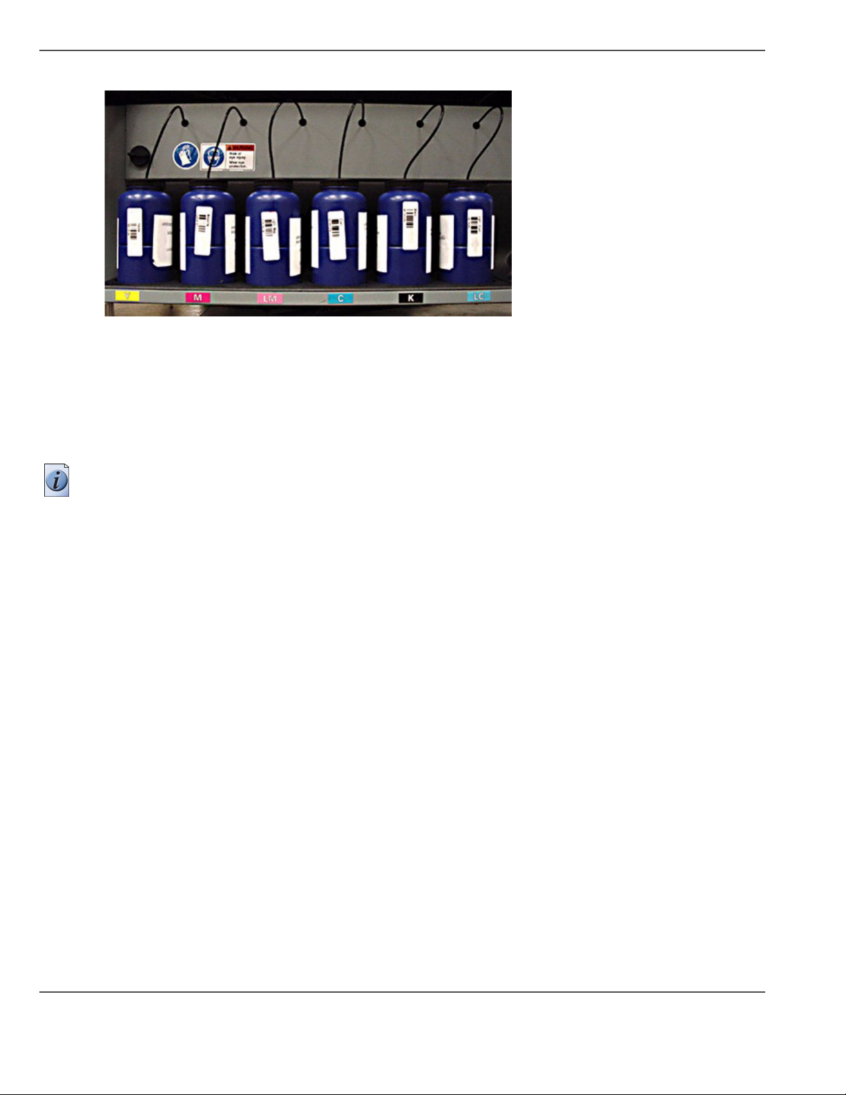
How to Change an Ink Bottle
Illustration
[48]
[48] Ink Bottles on Ink Station Tray
To replace an ink bottle
1. Unscrew the lid on a new ink bottle and remove the silver sealing foil.
2. Unscrew the lid on the empty ink bottle and unplug the coupler. Note that the lid stays attached to the ink line and
coupler. Put the old bottle aside and immediately place the coupler into the new ink bottle by pushing the flange all
the way into the ink pick-up insert.
Note: Important: Ensure that the coupler is fully inserted into the ink pick-up insert to prevent air being drawn into
the ink line when the pump is on.
3. Place the attached lid on the new ink bottle and screw it on tightly.
4. Dispose of the used ink in an environmentally friendly manner.
5. Press ACCEPT on the control panel to enter the color and begin printing.
72 Chapter 6 Ink System Management
Page 73

How to Scan Ink Barcodes
Introduction
Whenever you replace an ink bottle, scan the new bottle’s barcode. The T220UV printer calculates the amount of
ink used for each color printed and determines approximately when the volume for a bottle of each color ink is
finished. It also retains a record of previous barcodes. If you are prompted to enter the barcode from a bottle of ink
you may not necessarily have an empty ink bottle. If you changed the ink bottle without a barcode scan, eventually
you will see the following display on the control panel: "Ink Barcode expired Press ACCEPT to continue".
Illustration
[49]
How to Scan Ink Barcodes
[49] Barcode Wand
Scan a Barcode
1. Navigate to the Operator\Ink menu and select the color of ink to change/install. Press ACCEPT to continue and
you will see the following display: "Scan barcode (color XXX) ACCEPT -> Manual Entry".
2. Use the barcode wand located under the Control Panel to scan the barcode on the ink bottle. When the scan is
successful, the following confirmation display appears for a few seconds, then printing can continue: "Scan
Barcode: Light magenta RGIBC: xxxxxxxx".
Note: (Tip: hold the wand at a 45 degree angle while moving smoothly at a constant rate across the barcode).
Manual Entry of Barcode
1. Press ACCEPT during the Scan Barcode ACCEPT -> Manual Entry display to access the manual barcode routine.
2. Look up the string of digits located below the bar code on the ink botle, and enter them one at a time. Use the +
and - keys to cycle through the digits until you see the one you need.
3. Press ACCEPT to move to the next blank space and select the next digit.
4. When the last barcode digit is entered, press ACCEPT and the control panel displays: "Scan Barcode: color/
RGIBC: xxxx" (where xxxx is the barcode you just entered). After this confirmation, the printer can resume
printing.
73
Page 74
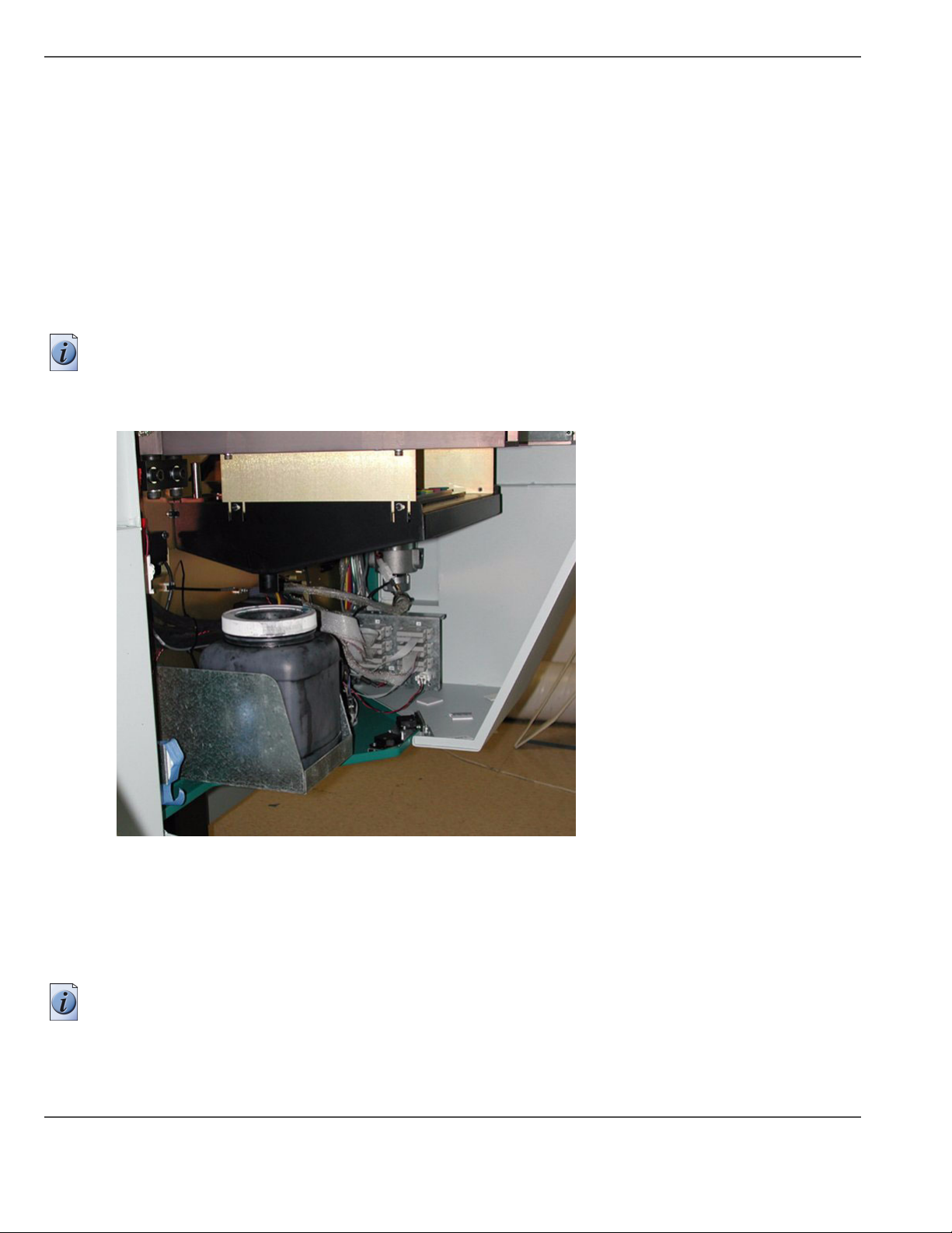
How to Empty the Waste Bottle
How to Empty the Waste Bottle
Introduction
The printer accumulates waste that is made up of ink and accumulated debris. The waste bottle is located on the
Home side of the gantry and is accessible by opening the gantry doors. A sensor monitors the waste level in the
bottle, and a high level is reported on the control panel.
When to do
The waste bottle should be emptied when the control panel indicates that the it is almost full. You can also do a
visual inspection to check the level and empty the waste bottle before it becomes full, if necessary.
Note: If you need to replace the waste bottle container with a new one, or if you require a spare bottle, order part
# 3010100266.
Illustration
[50]
[50] Gantry Doors Open To Access Waste Bottle
Empty the Waste Bottle
1. Remove the waste bottle from the bracket and put a cloth or paper towel in place to catch any drips while the bottle
is emptied.
2. Unscrew the lid and pour the waste into a suitable container for disposal.
Note: Dispose of the waste in accordance with local laws or as directed in the UV ink MSDS sheets — See “Safety
Information” section.
3. Replace the empty waste bottle by fitting it into the bracket.
4. Ensure that the lid is securely screwed on to the waste bottle.
74 Chapter 6 Ink System Management
Page 75

How to Change Blot Cloth
Introduction
The blot station is located in the left side of the gantry, opposite to the Home position. The blot paper is moved up
towards the carriage, by means of a single pneumatic cylinder. The blot paper is supplied on a roll and is advanced
using a motor. The motor has an encoder and a variable density optical sensor to determine the diameter of the
remaining blot paper, and therefore how far the motor needs to turn to advance the correct amount of paper. This is
also used to sense when the roll needs to be changed.
Purpose
A blot is required to remove excess ink and/or solvent from the printhead’s nozzle plates. Also, after an ink head
spit, the blot paper is used to soak up the excess ink.
When to do
The blot cloth is supplied in a roll. When the blot cloth requires replacing, a message is displayed for the operator
on the control panel.
How to Change Blot Cloth
Before you begin
Make sure that the blot station is in its default raised position. A latch is used to lower the blot Station to allow
access to the underside of the carriage - make sure this latch is in the upper position.
Attention: Do not re-use blot cloth as this may cause improper blot resulting in overspraying and poor quality
prints.
Note: Check the blot cloth periodically to make sure it is not "coning" (skewing to the side) as this can cause the
roll to fall off the spindle.
75
Page 76

How to Change Blot Cloth
Illustration
[51]
[51] Blot Station
76 Chapter 6 Ink System Management
Page 77

Installing New blot Cloth
1. Remove the old roll of blot cloth and discard.
2. Remove the old empty cardboard core and save it for use in Step 4.
3. Mount a new roll of blot cloth on the lower supports. Run the cloth up the back and over the top of the blot station.
4. Mount the old cardboard core on the upper supports ensuring that the pins on the spindle engage properly with the
notched core.
[52]
5. Remove the strip of backing tape from the start of the new roll and stick the new roll to the old core.
How to Change Blot Cloth
[52] Mounting the Old Cardboard Core
Note: Make sure that you align the cloth material and not the plastic material at the start of the roll to the old core.
6. Advance the new cloth by hand ensuring that there is no paper tape or loose fibers adhering to the cloth in the area
[53]
where the paper tape was stuck to the roll.
[53] Secure the New Blot Cloth
77
Page 78

How to Change Blot Cloth
78 Chapter 6 Ink System Management
Page 79

Chapter 7 Media Management
79
Page 80

How to Handle Media
How to Handle Media
Introduction
Océ Display Graphics Systems has conducted extensive testing of many media. Since the Arizona T220UV printer
is capable of imaging on a wide range of material, ODGS encourages you to explore various media so that you can
establish your own criteria for achieving high quality images in your work environment. Please consult the ODGS
web site at:
http://www.oce-dgs.com/PrinterSupport/T220_Customer/ T220_Customer_Access.htm
for access to PosterShop profiles.
Definition
The term media covers a wide range of possible materials for the Arizona T220UV printer. Essentially, any material
that is less than two inches (5 cm) thick, more than the minimum size of 6” wide x 6” long (15cm x 15cm) and less
than the maximum size of 62” wide x 120” long (158cm x 305cm), can be considered viable media. Some materials
will hold the ink better than others, so we encourage you to experiment with media to determine what works best
for your purpose.
Attention: Do not print on mirrors or any other highly reflective media as UV light is reflected off such media.
This results in curing the ink in the heads and thus damaging them.
Recommendations
■ Store media in the same environmental conditions as it will be used, avoid extremes in humidity and temperature.
Store media flat to reduce tendency to bow.
■ Handle media with lint-free gloves. Oil deposits from fingers will degrade print quality.
■ Ensure the media is free of any debris before you print. If necessary, use the recommended clean-room cloth
wipe (0505-0283 Cloth Poly-Wipe).
Carriage Collision Recovery
If the rotary media touch sensor on the front side of the carriage detects that something on the table is higher than
the media (or if the media is thicker than what is actually set in the print job settings), a carriage collision is about
to occur. If a collision occurs, the carriage will finish its active swath and then pause and flash the message “Pausing
Print Please Wait”, followed by “Media Collision Detected, press ACCEPT to continue”. While this message
displays a 15 minute countdown is shown in the top left corner. This indicates the amount of time the UV lamps
will stay on, allowing you to resolve the problem without shutting the lamps shutting down.
If you press ACCEPT the display shows “Gantry Move: ‘+’ -->Home. ACCEPT: continue CANCEL: cancel print”.
If CANCEL is pressed, the print job is aborted. Press the + key to move the gantry toward the Home position. This
allows the operator to clear whatever caused the collision. Press ACCEPT and you will see the message “Print is
Waiting press ACCEPT to continue”. Press ACCEPT again to allow the carriage to continue to print.
80 Chapter 7 Media Management
Page 81

Thermal Expansion of Media
When imaging on media that will expand when subjected to heat (e.g., styrene or plexiglass, etc.), don’t wedge the
media by butting other material against it as this may cause the media to buckle. Also if multiple pieces of the media
are used, allow enough space between the pieces to allow for thermal expansion. Placing tape on the table prior to
laying down the media will prevent ink from being imaged onto the table. Finally, if using overprinting on media
that will expand when heat is applied, we recommend that you group the desired image with a preceding image so
the printer is a consistent temperature when starting to print the desired image.
Note: Thermal expansion may cause color-to-color alignment problems.
How to Handle Media
81
Page 82
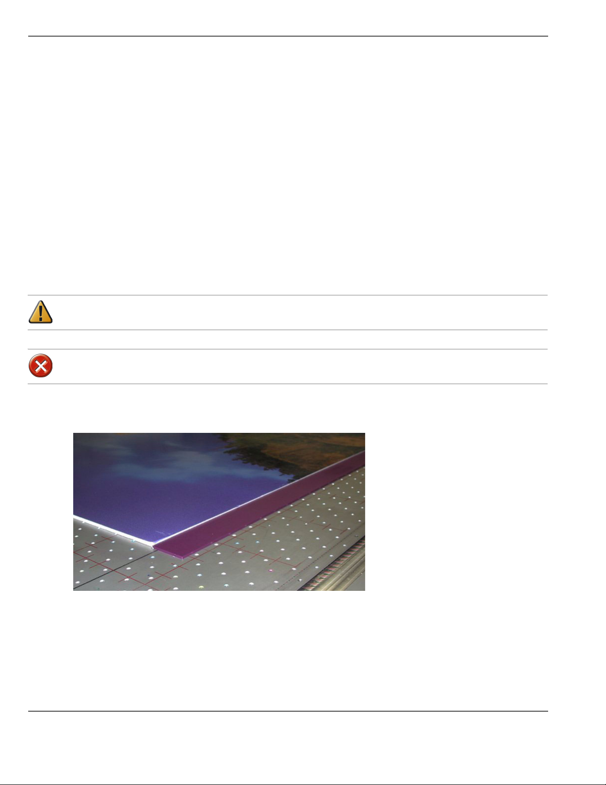
How to Use Media Holder Strips
How to Use Media Holder Strips
Introduction
Some media, such as Fome Cor, has a tendency to warp off the table when subjected to heat. This warpage can
result in a carriage collision. Media Holder Strips — which are shipped with the printer — help to limit this
possibility. Six strips may be required to border the long edges of a sheet of 4'x8' Fome Cor.
The media holder strips are 1/8" (3.2mm) thick. When using media with the media holder strips, 3/16" (4.8mm)
thick material should be used.
■ The strips can be printed on if a bleed is required in the image. If the strips are used for a bleed and the media
thickness is more than 2mm greater than the strips, overspray and nozzle dropout is likely to occur.
■ When not in use, the strips should be stored flat.
Purpose
The sharp edge of the media holder strip butts up against the middle of the edge of the media. This prevents warping
and increases the effect of the vacuum.
Attention: If you use the strips, make sure you do not use any media less then the thickness of the media holder
strips.
Caution: Do not print on mirrors or any other highly reflective media as UV light is reflected off such
media. This results in curing the ink in the heads and thus damaging them.
Illustration
[54]
[54] Foam Cor with Media Hold-Down Strip
82 Chapter 7 Media Management
Page 83
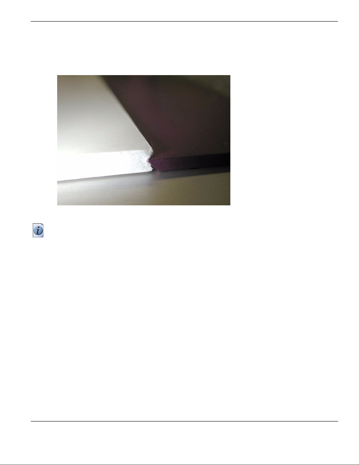
Directions for use:
1. Place the media on the table with a minimum offset of 2"(50mm).
2. Turn on the vacuum.
3. Mask off open vacuum zones with scrap pieces of media less than the height of the media printed on.
4. Push the strips up against the long edges of the media, with the sharp edge protruding into the middle part of the
[55]
media edge.
Use A Spoilboard Sheet to Reduce Artifacts
[55] Sharp edge of the strip against the media.
Note: The strips will be held in place by the vacuum holes underneath them, but you can also apply tape to ensure
that they are not moved out of the desired position.
Use A Spoilboard Sheet to Reduce Artifacts
Introduction
When printing on thin, flexible, or porous media, the counter-bore holes in the vacuum table of the T220UV can
cause print artifacts (sometimes referred to as “dimpling”). If you encounter this problem when printing, consider
adding a spoilboard sheet between the media and the table to reduce this problem.
Purpose
To reduces print artifacts (dimples) on thin media.
When to do
If you use a thin media that shows dimples that correspond to the holes in the vacuum table, then you may need a
spoilboard beneath your media to avoid this problem.
83
Page 84

Use A Spoilboard Sheet to Reduce Artifacts
Before you begin
North American contact information (a suggested source - other sources of similar products may be available. For
other areas, check your local hardware and router supply stores):
THERMWOOD Corp.
904 Buffaloville Road
PO Box 436 DALE, IN 47523
USA Contact: Melanie Tullis
Tel.1-800-221-3865 Ext. 266
email: Melanie.Tullis@thermwood.com
You can get more information from their website: http://www.woodworkerswholesale.com/
There are 2 spoilboard products from this manufacturer that we recommend for the Arizona T220UV.
Part # TA00827 - 1/4"x5'x10' (Actual Size: 1/4" x 61" x 121")
Part # TA00826 - 1/4"x4'x8' (Actual Size: 1/4" x 49" x 97")
Note: If you think that you need this product, you must buy directly from the manufacturer. We recommend that you
buy more than one sheet due to the shipping costs.
Illustration
[56]
[56] Spoilboard with Media
Tips On How to Use the Underlay Sheet:
1. Use scrap pieces of media to cover any exposed area of the underlay sheet that the carriage will travel over. This
prevents the spoilboard sheet from lifting off the table and colliding with the carriage.
2. It may be necessary to bleed the vacuum by opening, or partially opening an additional vacuum zone to reduce
dimple artifacts.
3. Confirm that the spoilboard (underlay) thickness is set correctly.
4. Select UL (underlay) when printing a job using the spoilboard.
84 Chapter 7 Media Management
Page 85

Chapter 8 Error Handling and Troubleshooting
85
Page 86

Troubleshooting Overview
Troubleshooting Overview
Introduction
This section covers general problems that may occur with the printer. Malfunctions that trigger system error
messages can be caused by human error, a system malfunction, an interface cable malfunction, mechanical printer
malfunction and/or printer firmware failure.
Definition
User-correctable Errors
User-correctable errors are problems that interfere with the print process but do not shut down the printer
completely. Typically, these errors are problems that prevent starting a printing job or that interrupt the current print.
You should be able to fix user-correctable errors without a service call. In most cases, the printer itself informs you
what is wrong by displaying an error message on the control panel. Check these common error messages and apply
the appropriate remedy.
System Errors
System errors stop the printer and prevent operation until the error is resolved.
Troubleshooting
Troubleshooting helps you locate the source of errors and fix common problems that can arise during printing.
However, before you investigate, check: Is the printer connected to a working power source?
Troubleshooting Areas:
■ Printer behaviour
■ Print quality
■ Data transfer
Example
If There is No Power
The service should be a dedicated supply that is not susceptible to voltage fluctuations. This service must be
provided via an independent, double pole, fused circuit breaker and a circuit ground (computer grade) located near
the machine. The service should meet all local and national standards for this type of installation. The circuit
breaker should be clearly labeled, indicating the On and Off positions, such as '1' for On and '0' for Off. A suitable
air gap should be maintained for safe electrical isolation when in the Off position. The Arizona T220UV printer
relies on this service for primary branch protection. If the printer is without power, check the local supply voltage
and verify that it is set correctly.
86 Chapter 8 Error Handling and Troubleshooting
Page 87

If Problems Persist
If problems persist, perform the following actions as appropriate for the situation:
• Check for media or an underlay sheet that is buckling or sitting too high on the table.
• If you just changed ink in the printer, review the procedures in this manual and check for successful installation.
• Try printing a test print.
• If the printer is not receiving print jobs, check the SCSI cable connection to/from the PC.
Note: If you still have problem indications, contact your Océ Display Graphics Systems service representative.
Call for Service
Trying to eliminate simple problems before calling your service representative is important, but knowing when to
call for service is also important. Without training, servicing the printer yourself may cause further damage. When
you have determined that a service call is required, call as soon as possible. Have the following information ready:
■ Printer serial number — located on Away side near the AC power plug.
■ The volume of media printed — available in the Operator /About Printer menu.
■ The type of computer and operating system acting as the print server.
■ Error message displayed on the operator control panel, if any.
■ The exact circumstances when the error occurred, such as during printing, or maintenance.
■ Note any unusual phenomena, such as peculiar printing, noises, and smells associated with the failure.
Troubleshooting Overview
87
Page 88

Troubleshooting Tips
Troubleshooting Tips
Introduction
This section indicates some potential problems you may encounter with your Arizona T220UV Printer and offers
possible solutions. If your problem is not solved by these or other suggestions in the Maintaining Print Quality
section, place a service call for qualified technical support.
Solutions
[27]
[27] Problems and Solutions (1 – 2)
Problem Solution
Cannot initialize
T220UVPrinter
Make sure the T220UV I/O is set to SCSI and not Parallel. Also for Windows 2000
and XP, go into the System / Hardware Settings / Device Manager and disable the
generic printer listed under IEEE 1394 devices and SCSI printers.
Rebooting the Computer
during Printing hangs the
This is not recommended, because when the computer initializes the SCSI host
adapter, it may hang the printer.
printer
Print Head is plugged or
not Firing.
Do a high purge. If there is no ink on the blotting cloth for the head it is plugged, if
there is ink then the head is not firing. Do a spit to see if the heads are spitting on the
blotting cloth. If the head is plugged try a recovery purge or two on just the offending
color. If the head is not firing, place a service call.
Vacuum squeals when
turned on
If the vacuum squeals when turned on, adjust the vacuum hose to change the airflow,
until the noise is eliminated. Try a tight coil in the hose. Once a good hose position
has been determined use duct tape to hold the hose in place. Also, check hose clamps
to verify they are tight and check that all connections are secure.
Contact Service if the problem persists - an upgrade kit is available.
Mist of Stray Ink Very fine ink droplets that have no directionality (looks like solar wind), may be
caused by static electricity. Use an anti-static device on the media or clean the media
with isoprophyl alcohol to reduce static. Also check that the media height is set
correctly.
Carriage crashing into the
media
If a media collision error occurs, fix the obstruction if easy to do so, then cancel the
print. However if the media is wedged between the carriage, do not attempt to remove
the jammed media, this could possibly damage the print heads. Instead reboot the
printer as this will automatically raise the carriage to the highest possible position
during the reboot sequence so the media can be removed.
SCSI ID 5 Oce Arizona
T220UV ASYN – Start
Unit Request Failed
The error is caused by booting the computer after the T220UVprinter has been
powered up but prior to it being online. Reboot the computer after the T220UVprinter
goes online.
(Error Message on
computer boot-up)
Cannot see PosterShop
Dongle
Custom color LAB values
are not retained in
PosterShop.
Problem may occur when reinstalling PosterShop on Windows 2000. Rebooting the
computer will not fix the problem, but repowering the computer works.
PosterShop does not retain the correct LAB value when reading a custom color
swatch. A three patch fix for 5.61 is available on the Oce FTP site.
ftp://ftp.cymbolic.com/Downloads/Inkjet/ArizonaT220/
Software/PosterShop_Patches/
88 Chapter 8 Error Handling and Troubleshooting
Page 89

[27] Problems and Solutions (2 – 2)
Problem Solution
Troubleshooting Tips
Problems rotating and
cropping images in
PosterShop
Color Replacement
Values not taking effect
This is a deficiency in PosterShop. It is best to rotate then crop. If the crop box and
image orientation gets messed up, revert back to the original PostScript settings and
try again. Sometimes when rotating selecting the “swap width and height” option in
the preflight preview and size dialog will also help fix the problem.
After replacing a color with another you need to go back to Preview and Size and hit
the apply button to re-render the file.
89
Page 90

System Errors
System Errors
Introduction
System errors stop the printer and prevent operation until the error is resolved. Many system error messages indicate
the source of the problem and state that the error can be cleared by pressing the ACCEPT button on the control
panel.The following table contains some of the common printer errors. There are other errors, and generally the
message provides you with an idea of the problem and how to solve it. If the problem persists or if you are unsure
of how to proceed, record the error message and contact your Océ service representative.
T220UV Error Messages
[28]
[28] Error Messages
Error Message Possible Cause and Response
“WARNING: SAFETY
INTERLOCK
BYPASSED”
"SYSTEM ERROR
[press ACCEPT to restart]"
"BLOTTER MOTOR or
ENCODER"
"Lamp Warmup timeout.
Cancelling print"
"Press ACCEPT to
Continue"
“Lamp xx is out, uv power is
off”
“press ACCEPT to
continue”
“Reflector overtemp
interlock open”
“press ACCEPT to
continue”
“Carriage temp is too high”
“print cancelled, press
ACCEPT”
Refer to possible causes in section “Emergency Stop” (see ‘Operator Control
Panel’ on page 34)
The blot cloth is not moving.
Might be out of cloth or stuck.
The illuminator could not reach its minimum temperature (default 120F/49C ) in
its allotted time (10 minutes).
Might be a sensor problem or bad cabling - call for service.
The lamp(s) have unexpectedly gone off. This error should be recorded, but no
action is required unless the problem is persistent.
If persistent, a service call is in order.
Illuminator over-temp pop out has triggered. Possible problem with illuminator fan
or other cooling problem. Check that the lamp is on and also that the carriage fan
is plugged into the carriage cover and the gantry fans are all running.
If problem persists, call for service.
The carriage temperature has exceeded its maximum range. There may be a fan not
working or other mechanical failure relating to the cooling system (air flow). The
printer may also be printing above its operating range. Check that the room
temperature is not too high and that all fans are working.
"Carriage out of safety zone"
"press ACCEPT to continue"
90 Chapter 8 Error Handling and Troubleshooting
The carriage has stopped with its lamps on in the middle of the gantry.
If problem persists, call for service.
Page 91

T220UV Lamp Bulb Replacement
Introduction
This section describes how to change a UV lamp bulb when it burns out. These instructions are also contained in
the kit that you receive with a replacement lamp. Note that each kit contains only one lamp, so if both lamps burn
out you need to order two kits.
Kit Contents (Part #3012002526):
■ Cotton gloves (1 pair)
■ 2 optical cleaning wipes
■ 3mm Allen key
■ MSDS UV Lamp Safety Data Sheet
■ UV lamp bulb
■ Lamp replacement instructions
Purpose
To replace a UV lamp when it has burned out.
T220UV Lamp Bulb Replacement
Before you begin
If you need to replace the lamp on the blot side, first use the control panel Operator/Maintenance menu to issue the
"Access Carriage" command before turning the power off. This moves the carriage to the blot side for easy access
to the UV illuminator on that side. This is not necessary when replacing the bulb on the carriage side.
Note: When replacing the lamp bulb in the illuminator at the blot cloth station, be aware that with the power off
you cannot move the carriage manually. Also, there is no vacuum to hold the ink in the system. Eventually, the ink
will start to drip from the heads. Make sure that the carriage is parked directly over the blot cloth so that it will
absorb any drips of ink. Also, when you power the printer on again, make sure that you advance the blot cloth
manually to a clean area of the roll if any ink has spilled on it. This is not an issue when replacing a bulb on the
carriage side since the waste tray will collect any spilled ink.
Required tools
Philips screwdriver,
Protective clear glasses.
Caution: UV lamps may still be hot for a while after the printer power is set to Off in Step 2. Wait a few
more minutes after power is Off to let the illuminators cool down. Check the temperature before you
handle the illuminators.
91
Page 92
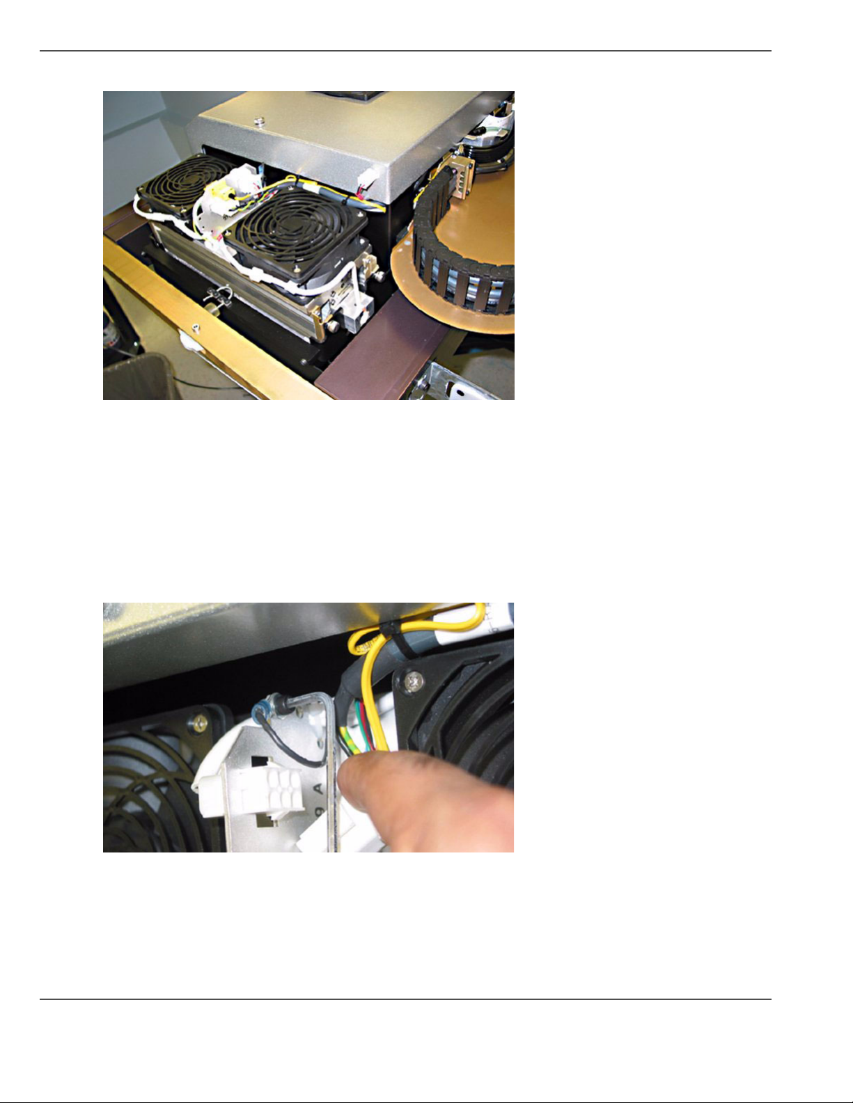
T220UV Lamp Bulb Replacement
Illustration
[57]
[57] Illuminator Lamp on Carriage Side
Procedure for Bulb Replacement
1. If the UV lamps are on (even if one has burned out, the other may still be on) use the Operator/Maintenance/turn
on/off uv lamp menu to turn the lamps off. Wait until you see “Ready” displayed in the top left corner of the control
panel display before proceeding to step 2. This ensures that the UV illuminators have cooled.
2. Turn the printer's power off and prepare a workspace on a flat surface with a clean drop cloth. Make sure the lamp
is cool before you continue.
3. Open the gantry doors on the side that the lamp bulb will be replaced
[58]
4. Disconnect the ground strap using the 3mm allen wrench.
[58] Disconnect Grounding Strap
Disconnect the thermal sensor cable.
5.
92 Chapter 8 Error Handling and Troubleshooting
Page 93

T220UV Lamp Bulb Replacement
[59]
[59] Disconnect Thermal Sensor
Disconnect the two lamp connectors.
[60]
6.
[60] Disconnect Lamp Connectors
93
Page 94

T220UV Lamp Bulb Replacement
[61]
7. Loosen (by hand, but do not remove) the four corner thumbscrews that secure the illuminator in the carriage.
[61] Loosen Corner Screws.
Carefully lift out the illuminator. Place the illuminator on its side on a flat surface and do not lift or move the
8.
[62]
illuminator during the remaining steps to prevent the quartz window from falling onto the bulb.
[62] Remove Illuminator.
94 Chapter 8 Error Handling and Troubleshooting
Page 95
T220UV Lamp Bulb Replacement
[63]
[64]
9. Remove the lamp power cable by prying open the plastic brackets and disconnect the two power cable connectors.
[63] Remove Power Cable
[64] Disconnect Cable Connectors
95
Page 96

T220UV Lamp Bulb Replacement
10. Loosen (but do not remove) both Phillips screws on both side plates that hold the lamp. Pivot the plates out of the
[65]
way of the bulb.
[66]
[65] Remove Side Plate Screws
[66] Pivot Plates out of the way
96 Chapter 8 Error Handling and Troubleshooting
Page 97

T220UV Lamp Bulb Replacement
11. Loosen (but do not remove) both screws (Phillips) on both side plates beneath the bulb and slide out the plates.
[67]
[68]
[67] Remove Screws
[68] Slide Plates Out
Put on cotton gloves for the next seven steps.
12.
97
Page 98
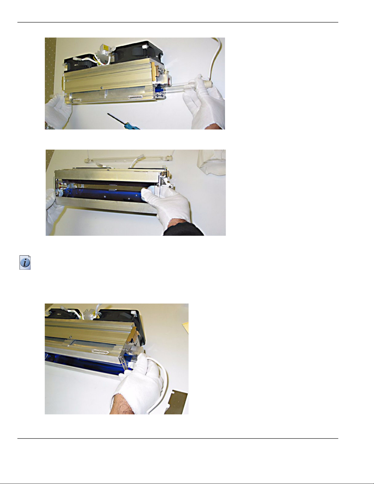
T220UV Lamp Bulb Replacement
13. Remove the lamp bulb by carefully sliding the bulb through the housing.
[69]
[69] Remove Lamp Bulb
Remove the quartz window by sliding it out very carefully.
14.
[70]
[70] Remove Quartz Window
15. Gently clean the window using the provided optical cleaning wipes only.
Note: Do not scrub hard to prevent the window coating from scratching. Do not clean the interior of the illuminator.
16. Remove the new bulb from its packaging. Only hold the bulb from its edges, not the middle. Clean the bulb using
the provided opical wipe.
17. Slide the bulb into the illuminator. Press the bulb into place and secure the bulb by pivoting the side plates back into
[71]
place and screwing (Phillips) hand tight.
[71] Insert UV Bulb
98 Chapter 8 Error Handling and Troubleshooting
Page 99

T220UV Lamp Bulb Replacement
18. Return the window into illuminator by carefully sliding it into the housing. Take care not to drop the window onto
[72]
the bulb.
[72] Re-insert Quartz Window
Return the side plates beneath the bulb by screwing (Phillips) hand tight. Gloves are no longer required.
19.
20. Reconnect the lamp power cables and return them into their brackets.
[73]
[73] Reconnect Power Cables
21. Return the illuminator into the carriage and secure the four hand screws.
[74]
[74] Return Illuminator
99
Page 100

T220UV Lamp Bulb Replacement
22. Reconnect the ground cable (Allen wrench), the thermal sensor, and two lamp power connectors.
[75]
[75] Cable, Sensor and Power Connectors
Close the gantry doors.
23.
24. Turn the printer power ON.
Note: In order to track lamp usage and to estimate lamp replacement schedules, always re-set the usage statistics
after replacing a lamp bulb.
Re-set the Lamp Usage Statistics
1. In the Operator/Maintenance menu press the MENU button until you see Lamp Usage.
2. Press ACCEPT to enter the Lamp Usage menu. Press MENU until you see “reset lamp usage”.
3. Press ACCEPT to see “reset lamp usage: lamp B”. If you have changed the Blot side lamp, press ACCEPT. If you
changed the Carriage side lamp, press the + or - key to select lamp C, then press ACCEPT.
4. Press ACCEPT one more time and the lamp use time and number of strikes will be re-set to zero.
100 Chapter 8 Error Handling and Troubleshooting
 Loading...