

Page 1

Océ CS7075
Océ CS7100
User Manual
for Océ UV curable inkjet printers
0706341 Rev B
Page 2

Océ Display Graphics Systems Inc.
13231 Delf Place, Suite 501
Richmond, BC V6V 2C3
Canada
Telephone: +1 604 273 7730
Fax: +1 604 273 2775
http://www.oce.com
© 2006 MacDermid ColorSpan, Inc. All rights reserved. Printed in the
United States of America.
No part of this document may be reproduced, copied, adapted, or transmitted in any form or by any means without express written permission
from MacDermid ColorSpan, Inc.
MacDermid ColorSpan, Inc. makes no representations or warranties with
respect to the contents of this manual. Further, it reserves the right to
revise or change this publication without obligation to notify any person
of such changes.
ii Copyright
Page 3

Revision Log The following is a list of major changes and additions that have
been made to this manual since it was first released.
See the accompanying Release Notes for specific changes to the
sof t ware and hardware bet ween manual updates.
Revision Description
Revision B Initial release.
iii
Page 4

Regulatory Statements
FCC-A This equipment has been tested and found to comply with the
limits for a Class A digital device, pursuant to Part 15 of the FCC
Rules. These limits are designed to provide reasonable protection against harmful interference when the equipment is operated in a commercial environment. This equipment generates,
uses, and can radiate radio frequency energy and, if not installed
and used in accordance with the instruction manual, may cause
harmful interference to radio communications. Operation of this
equipment in a residential area is likely to cause harmful interference in which case the user will be required to correct the
interference at his or her own expense.
This equipment must be installed exactly as instructed in this
manual using only the components supplied. If a supplied component ever needs to be replaced, it must be replaced with the
same part supplied by the manufacturer. It is your responsibility
to follow these instructions in order to maintain compliance
with the FCC regulations. Changes or modifications not
expressly approved by ColorSpan Corporation could void your
authority to operate this equipment. In particular, this device
must be operated with shielded cables to maintain FCC
compliance.
A booklet is available from the Federal Communications Commission entitled, How to Identif y and Resolve Radio-TV Interfer-
ence Problems (#004-000-00345-4). Write to the U.S.
Government Printing Office, Washington, DC 20402.
DOC (Canada) This digital apparatus does not exceed the Class A limits for
radio noise for digital apparatus set out in the Radio Interference Regulations of the Canadian Department of Communications.
Normes de Sècuritè (Canada)
Le présent appariel numérique n’émet pas de bruits radioélectriques dépassant les limites applicables aux appareils numériques
de la Classe A prescrites dans le réglements sur le brouillage
radioélectrique édictés par le Ministére des Communications du
Canada.
iv
Page 5

Telecommunications
Network Statement
The ColorSpan VideoNet port on this device is not intended to
be connected to a public telecommunications network. Connection of this device to a public telecommunications network in a
European Community Member State will be in violation of
national law implementing Directive 91/263/EEC on the approximation of laws of the Member States concerning telecommunication terminal equipment, including the mutual recognition of
their conformity.
Der VideoNet port ist nicht dafür vorgesehen an ein öffentliches
Telefonnetz angeschlossen zu werden. Der Anschluß dieses
Gerätes an ein öffentliches Telefonnetz in einem Mitgliedstaat
der EU, verstößt gegen nationale Gesetze zur Ausführung der
Direktive 91/263/EEC, die sich mit der Annäherung von
Gesetzen von Mitgliedstaaten beschäftigt, betreffend Telekommunikt ionsanlagen und die gegenseitige Anerkennung ihrer
Konformität.
v
Page 6

About This Manual Read this manual to unpack, set up, and use the printer.
◆ Chapter 1, Getting Started, introduces you to the main fea-
tures of the printer.
◆ Chapter 2, Using the Control Panel, shows you how to use
the control panel to specify printer options.
◆ Chapter 3, Ink and Media, shows you how to install ink and
media.
◆ Chapter 4, Calibrating the Printer, shows you how to cali-
brate the printer for optimal print quality.
◆ Chapter 5, Maintaining the Printer, explains scheduled
maintenance, how to recover clogged printheads, how to
prepare the printer for extended power-down (such as for
shipping or storage), and more.
◆ Appendix A, Technical Specifications, lists the printer’s
technical specifications.
◆ Appendix B, Troubleshooting, shows you how to trouble-
shoot common printing problems and interpret Action and
Warning messages.
vi
Page 7
Conventions This manual uses the following informational conventions:
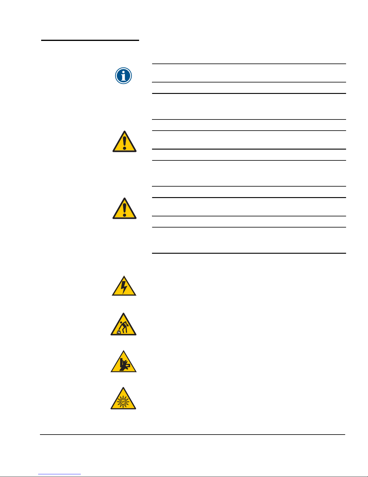
Note
Hinweis
Caution
Vorsicht
WARNING
WARNUNG
A special technique or information that may help
you perform a task or understand a process.
Ein Hinweis beschreibt eine spezielle technik zur
Lösung einer Aufgabe oder enthällt Informationen,
die Ihnen eine Prozedur näher erläutert.
Alerts you to something that has the potential to
cause damage to hardware, software, or data.
Dieses Feld weist auf einen Umstand hin, der einen
Hardware-oder Software-Schaden oder Datenverlust
verursachen könnte.
Alerts you to something that has the potential to
cause physical harm to you or others around you.
Eine Warnung auf weist auf einen Umstand hin,
durch den Ihnen und anderen Personen ein physischer Schaden erwachsen könnte.
Other WARNING symbols used:
Electrical Hazard
Vorsicht steht unter Spannung
Lifting Hazard
Vorsicht beim Anheben
Moving Parts
Bewegliche Teile, Verletzungsgefahr.
High Intensity UV Light
UV Licht hoher Intensität. Bitte vermeiden Sie es, direkt in die
Lampen zu schauen.
vii
Page 8

viii
Page 9

TABLE OF CONTENTS
Revision Log..............................................................................................iii
Regulatory Statements.............................................................................. iv
FCC-A ....................................................................................................iv
DOC (Canada)...................................................................................... iv
Telecommunications Network Statement..............................................v
About This Manual ...................................................................................vi
Conventions............................................................................................. vii
Getting Started
Operating Requirements ....................................................................... 1-2
Electrical............................................................................................. 1-2
Environmental.................................................................................... 1-3
Important Operating Notes................................................................... 1-4
Safety Warnings................................................................................. 1-6
Workflow Overview ............................................................................... 1-8
Daily Startup ...................................................................................... 1-8
Recover Jets Part 1 ............................................................................. 1-8
Recover Jets Part 2 ........................................................................... 1-10
600x300 Printing ......................................................................... 1-13
Daily Shutdown ............................................................................... 1-14
Parts Overview..................................................................................... 1-15
Special Features ................................................................................... 1-19
Printheads ........................................................................................ 1-19
Ink System........................................................................................ 1-19
Calibration ....................................................................................... 1-19
Media Handling............................................................................... 1-20
Performance and Ease-of-Use .......................................................... 1-21
Table of Contents ix
Using the Control Panel
Overview................................................................................................ 2-2
Ready Screen...................................................................................... 2-2
Front Page.......................................................................................... 2-2
Menu.................................................................................................. 2-2
User Assistance................................................................................... 2-3
Front Page.............................................................................................. 2-4
Navigation Keys ..................................................................................... 2-9
Menu.................................................................................................... 2-10
Calibrate Printer............................................................................... 2-10
Printer Settings................................................................................. 2-11
Maintenance.................................................................................... 2-15
Page 10

Service Printer .................................................................................. 2-16
User Diagnostics .............................................................................. 2-16
Warnings & Actions ......................................................................... 2-16
Print Menu Tree ............................................................................... 2-16
Menu Tree............................................................................................ 2-17
Front Page........................................................................................2-17
Menu................................................................................................ 2-18
Ink and Media
Ink System Overview.............................................................................. 3-2
UV Lamp Overview ................................................................................ 3-3
Selecting a Print Mode........................................................................... 3-5
Checking Jet Health ............................................................................... 3-9
Print Prime Bars.................................................................................. 3-9
Map Out Missing Jets ........................................................................ 3-9
Print Jet-Out Lines............................................................................ 3-10
Loading Ink .......................................................................................... 3-11
When to Load Ink ............................................................................ 3-11
Unloading an Empty Ink Box........................................................... 3-11
Loading a Full Ink Box ..................................................................... 3-11
Pause-Swapping Ink.........................................................................3-13
Loading Roll-Fed Media....................................................................... 3-14
Support for Large Narrow Media Rolls ............................................ 3-15
Unloading and Cutting Roll-Fed Media............................................... 3-21
Takeup Spool Pin Release ................................................................ 3-22
Respooling Media ................................................................................ 3-23
Printing Tips......................................................................................... 3-25
Using the Media Tables ....................................................................... 3-26
Loading Rigid Media............................................................................ 3-27
Unloading and Reloading Rigid Media ............................................... 3-34
Edge-to-Edge Printing..........................................................................3-35
Document, Application, and RIP Settings........................................ 3-35
Media Properties.............................................................................. 3-36
Printer Setup .................................................................................... 3-36
Loading and Squaring the Media.................................................... 3-37
Example............................................................................................ 3-38
Document Design........................................................................ 3-38
Media Properties.......................................................................... 3-38
Printer Setup ................................................................................ 3-39
Media Wizard....................................................................................... 3-41
x Table of Contents
Page 11

Calibrating the Printer
When to Calibrate.................................................................................. 4-2
AutoJet ................................................................................................... 4-3
AutoTune ............................................................................................... 4-4
Quality Check .................................................................................... 4-5
Auto Calibrations ................................................................................... 4-6
Manual Calibrations .............................................................................. 4-8
Media Feed........................................................................................ 4-9
Manual X Head Registration............................................................ 4-12
Manual BiDi Registration................................................................. 4-15
Manual Jet Mapping........................................................................ 4-18
Report Individual Bad Jets ........................................................... 4-20
Clear Individual Bad Jets ............................................................. 4-21
View Current Bad Jets.................................................................. 4-22
Clear All Bad Jets.......................................................................... 4-22
Jet Status Lines................................................................................. 4-24
Default Registration Data ................................................................ 4-24
Calibration Summary........................................................................... 4-25
Straightening the Media Path.............................................................. 4-26
Linearization ........................................................................................ 4-27
Maintaining the Printer
Maintenance Schedule .......................................................................... 5-2
Clean the Rail and Bearings................................................................... 5-4
Pinch Rollers....................................................................................... 5-4
Rail ..................................................................................................... 5-5
Carriage Bearings............................................................................... 5-5
Recover Missing Ink Jets ........................................................................ 5-7
Set the Printhead Height ..................................................................... 5-11
Calibrate the Wiping Position.............................................................. 5-14
Clean the Wiping Station..................................................................... 5-15
Replace Ink Filters................................................................................ 5-16
UV Lamp Operation and Maintenance................................................ 5-18
Operating Tips ................................................................................. 5-19
Replacing UV Lamp Bulbs................................................................ 5-20
Balancing Lamp Hours..................................................................... 5-20
Clean the Quartz Windows ................................................................. 5-21
Clean the Ionizer Bar ........................................................................... 5-23
Printhead Procedures........................................................................... 5-24
Extended Power Down and Restart..................................................... 5-25
Power Down .................................................................................... 5-25
Restart .............................................................................................. 5-26
Table of Contents xi
Page 12

Technical Specifications
Specifications .........................................................................................A-2
Supplies and Accessories .......................................................................A-6
Troubleshooting
Troubleshooting Checklist ..................................................................... B-2
Head Strike Recovery ......................................................................... B-4
Warranty Claims..................................................................................... B-6
Diagnostics............................................................................................. B-8
Index
xii Table of Contents
Page 13

CHAPTER 1
Getting Started
This chapter shows you how to get started using your printer. It includes
these topics:
◆ Operating Requirements (page 1-2)
◆ Important Operating Notes (page 1-4)
◆ Workflow Overview (page 1-12)
◆ Parts Overview (page 1-19)
◆ Special Features (page 1-23)
Getting Started 1-1
Page 14

Operating
Requirements
Choose a location for the printer before you unpack it. Keep the
following requirements in mind:
Electrical ◆ Use the supplied power cord. Plug it directly into a grounded
electrical outlet. Do not lengthen the power cord with an
extension cord; the resulting drop could damage the printer.
◆ Make sure the line voltage meets the requirements: 220 VAC
±10%, 20 Amps, with NEMA L6-20R locking wall receptacle
(North America and Japan), OR 220 VAC ±10%, 16 Amps,
single phase, with IEC 60309 wall receptacle (Europe). See
Appendix A, Technical Specifications, for details.
◆ The printer requires a stable power supply to ensure acceptable output and sufficient voltage to light the UV lamps. If
necessary, you can purchase and install a voltage regulator
to ensure acceptable printer performance. Refer to the Site
Preparation Guide for specifications.
◆ The UV lamp power supply is connected to the included
power line conditioner that provides steady and consistent
voltage for optimal performance.
Caution
◆ To maintain vacuum to the printheads during printer powerdown, use the auxiliary 24 volt power supply (included in
the accessory kit with universal power adapters). Connect
the 24 VDC jack on the vacuum/pressure assembly to either
of two options:
◆ 1. UPS — customer-supplied uninterruptable power sup-
◆ 2. Wall outlet — 100-240 VAC, 50/60 Hz, provides tem-
◆ Connect the RIP to a separate electrical circuit from the
printer.
Only equipment that is specified by Océ should be
connected to the line conditioner. Do not remove the
safety plugs from the line conditioner outlets.
ply, output 100-240 VAC, 50/60 Hz, minimum of 15 watts
of power, provides battery backup to the vacuum system in the event of a power failure.
porary power to the vacuum system when it is necessary to power down the printer for service.See Appendix
A, Technical Specifications, for details.
1-2 Operating Requirements
Page 15

Environmental ◆ Make sure the room is well ventilated, with a temperature
and relative humidity within specifications (see “Specifications” on page A-2). Optimal printing and occurs within
these ranges.
◆ The high power UV light emitted by the curing lamps reacts
with oxygen and produces ozone. This formation tends to be
greatest during lamp start-up. The printer should be operated in a well-ventilated area to avoid minor effects such as
headaches, fatigue, and dryness of the upper respiratory
tract. Normal air movement will mix the ozone with fresh air,
causing it to revert back to oxygen.
◆ Store media and ink in an area with similar temperature and
humidity conditions as the printer.
◆ Locate the printer close enough to the RIP so that they can
be connected with the required cable.
◆ Locate the printer on a flat, level floor.
◆ Locate the printer where its normal operating noise will not
disturb quiet work areas.
◆ DO NOT install the printer near humidifiers, refrigerators,
fans, water faucets, heaters or similar equipment.
◆ DO NOT install the printer in areas where the temperature
changes abruptly, such as near air conditioners or in the path
of direct sunlight.
◆ DO NOT expose the printer to flames or dust.
Operating Requirements 1-3
Page 16

Important Operating
Notes
◆ UV CURE INK IS PERISHABLE. Unlike other
inks used in wide format printing, UV cure ink
has a limited shelf life. Plan to rotate your ink
stock and use it promptly by the date printed on
the ink box.
◆ DO NOT POWER DOWN THE PRINTER. Constant vacuum at
the printheads is required to prevent ink from flowing from
the printheads when not printing. If the printer must be
powered down for shipping see “Extended Power Down and
Restart” on page 5-25, or apply auxiliary 24 volt power.
Caution
Caution
◆ To dab the printheads, use only Océ IJC700 UV Printhead
Flush. (See “Recover Missing Ink Jets” on page 5-7 for
instructions.) DO NOT USE ISOPROYPL ALCOHOL.
◆ The maximum diameter allowed on the takeup spool is 7.5
inches (190.5 mm) on a 3-inch core. When the takeup spool
has a diameter of 6.5-7.5 inches (165.0-190.5 mm), the control panel displays a warning about possible print quality
issues. The supply-takeup system can support rolls of up to
approximately 125 pounds (56.7 kg).
Do not switch off the UV lamp power supply
unless the lamps have fully completed their controlled cool-down cycle (with fans and heat extrac-
tion). Removing power from hot lamps can result in
overheating and permanent damage. If sudden
removal of power occurs, contact Océ Display Graphics Systems Technical Services before starting the
printer again.
Do not connect any equipment to the line conditioner for the UV power supply, except as specified
by Océ.
1-4 Important Operating Notes
◆ The media supply may be wound either printed-side-out or
printed-side-in, but the takeup, if used, must be loaded
printed-side-in.
◆ The default head height set to 0.085 inches (2.2 mm) above
the media. (The space below the carriage will measure to
0.070 inches due to the printhead protection frame around
the outside of the carriage.)
Page 17

◆ If the height of sheet-fed media exceeds 0.25 inches (6.35
mm), you must prepare the printer as follows before printing:
◆ Raise the head height
◆ Raise the right-side louver assembly
◆ Install the left-side light-blocking mat
The printer detects when the media thickness is equal to or
exceeds 0.25 inches, and prompts you to perform these
steps. See “Loading Rigid Media” on page 3-27 for instructions.
◆ The Media Wizard stores a set of operational parameters for
predefined and user-defined media types. When you load a
new media type, select an existing Media Wizard set, or create a custom set. Media Wizard parameter sets can be
selected at any time from the control panel. (See “Media
Wizard” on page 3-41 for details.)
◆ Enable AutoTune during long periods of unattended printing. AutoTune runs AutoJet at user-defined intervals to
ensure that all jets are either working or substituted with
working jets. (See “AutoTune” on page 4-4 for instructions.)
◆ Wear cotton gloves when loading media to prevent fingerprints that could show after printing.
◆ DO NOT rest or store a media roll on end, or you could
cause edge creases that could strike the printheads during
printing.
◆ DO NOT clean the printhead surfaces with a dry cloth or
paper towel of any kind. Use only a lint-free (Class 100 cleanroom) cloth, such as those supplied with the printer, moistened with Océ IJC700 UV Print Head Flush.
◆ DO NOT reprint over any output that has not completely
cured. The rubber pinch rollers could be damaged by wet
ink. If ink does get onto the pinch rollers, clean them with a
minimal amount of isopropyl alcohol and dry them thoroughly before printing.
◆ DO NOT set heavy objects on the power cord or printer
cable; do not bend the cables or force them into contorted
positions.
◆ DO NOT place heavy objects anywhere on the printer.
Important Operating Notes 1-5
Page 18

Safety Warnings ◆ UV light — the ultraviolet (UV) curing lamps emit high
power UV light. The printer must be operated with all safety
shielding installed to protect the operator from eye and skin
damage. When operated according to manufacturer’s
instructions, safety glasses or other protective clothing are
not necessary.
◆ Mechanical hazards — Keep fingers away from carriage and
media path. The printer is too heavy to be lifted safely by
one person. At least three persons are required to lift the
printer. Do not exceed the maximum weight load of the
input or output tables, as printed on the label.
◆ Ink — read and practice safety guidelines as outlined in the
Material Safety Data Sheet (MSDS) for the ink, and post the
document in the work area as required by prevailing law.
Avoid any contact with skin and eyes. Provide adequate general and local exhaust ventilation. Avoid breathing vapors.
Respirator protection may be required under exceptional circumstances when excessive air contamination exists. None of
the component substances have established exposure standards per OSHA, NIOSH or ACGIH.
◆ Electrical — WITH THE POWER SWITCH IN THE OFF POSI-
TION, POWER MAY STILL BE SUPPLIED TO THE PRINTER
COMPONENTS. To completely cut power from the printer,
you must unplug the power cords from the power outlets.
◆ Ozone — the high power UV light emitted by the curing
lamps reacts with oxygen and produces ozone. This formation tends to be greatest during lamp start-up. The printer
should be operated in a well-ventilated area to avoid minor
effects such as headaches, fatigue, and dryness of the upper
respiratory tract. Normal air movement will mix the ozone
with fresh air, causing it to revert back to oxygen.
◆ Hazardous waste — THE PRINTER ELECTRONICS ASSEMBLY
CONTAINS A LITHIUM BATTERY DEVICE. THERE IS A DANGER OF EXPLOSION IF THE BATTERY IS INCORRECTLY
REPLACED. The battery must be replaced only by authorized service providers, and must be replaced only with the
same or equivalent type. Dispose of this lithium battery
device in accordance with local, state (or province), and Federal (or country) solid waste requirements.
1-6 Safety Warnings
Page 19

German ◆ UV-Licht – die ultravioletthärtenden Lampen strahlen
Hochleistungs-UV-Licht ab. Der Drucker muss mit allen
installierten Sicherheitsabschirmungen betrieben werden,
um den Bediener vor Augen- und Hautschäden zu schützen.
Sicherheitsbrillen oder andere Schutzkleidung ist nicht
erforderlich, wenn gemäß den Herstelleranweisungen gearbeitet wird.
◆ Mechanische Risiken – Halten Sie die Finger fern vom Lauf-
wagen und von der Medienzuführung. Überschreiten Sie
nicht die maximale Gewichtsauslastung der Eingabe- oder
Ausgabetische, die auf dem Etikett aufdruckt sind.
◆ Tinte – lesen und beachten Sie die Sicherheitsrichtlinien, wie
sie im Material- Sicherheitsdatenblatt (MSDS) für die Tinte
dargestellt sind und bringen Sie das Dokument, wie von der
aktuellen Rechtsprechung gefordert, im Arbeitsbereich an.
Vermeiden Sie jeden Kontakt mit Haut und Augen. Stellen Sie
ausreichende generelle und lokale Absaugvorrichtungen
bereit. Vermeiden Sie das Einatmen von Dämpfen. Eine
Atemschutzmaske könnte unter außergewöhnlichen
Umständen, wenn erhöhte Luftverschmutzung besteht,
erfoderlich sein. Keine der Bestandteile haben Gefahrenstandards nach OSHA, NIOSH oder ACGIH etabliert.
◆ WARNUNG — WENN DER NETZSCHALTER IN OFF POSITION
STEHT, WIRD DEN KOMPONENTEN TROTZDEM STROM
ZUGEFÜHRT. Um den Drucker komplett stromfrei zu machen,
müssen Sie den Netzstecker ziehen.
◆ Ozon – das Hochleistungs-UV-Licht, das von den Aushär-
tungslampen abgegeben wird, reagiert mit Sauerstoff und
produziert Ozon. Diese Entwicklung ist am größten,
während die Lampe hochgefahren wird. Der Drucker sollte
in einem gut gelüftetem Umfeld betrieben werden, um geringfügige Auswirkungen, wie Kopfschmerzen, Müdigkeit
und Austrocknen der oberen Atemwege zu vermeiden. Die
normale Luftbewegung vermischt das Ozon mit Frischluft,
wodurch es wieder zu Sauerstoff umgewandelt wird.
◆ WARNUNG — DIE ELEKTRONIK DES DRUCKERS ENTHÄLT
EINE LITHIUM BATTERIE. ES BESTEHT EXPLOSIONSGEFAHR
WENN DIESE UNSACHGEMÄSS AUSGEWECHSELT WIRD. Die
Batterie darf nur durch einen MacDermid ColorSpan authorisierten Technicker ausgewechselt werden und muss mit
dem gleichen oder einem gleichwertigen Typ Batterie ersetzt
werden. Bitte entsorgen Sie die Lithium Batterie gemäss
Ihren Landesoder Bundesgesetzen.
Safety Warnings 1-7
Page 20

◆ Residuos Peligrosos — EL GRUPO ELECTRÓNICO DE LA
IMPRESORA CONTIENE UNA BATERÍA DE LITIO. EXISTE
RIESGO DE EXPLOSIÓN SI LA BATERÍA ES REEMPLAZADA DE
FORMA INCORRECTA. La batería debe ser reemplazada únicamente por personal técnico autorizado y sólo por otra
igual o equivalente. Deshágase de esta batería de litio según
los requisitos de tratamiento de residuos sólidos establecidos por su localidad, provincia y país.
1-8 Safety Warnings
Page 21

Spanish ◆ Luz UV — Las lámparas de curado ultravioleta (UV) emiten
luz UV de alta intensidad. La impresora debe ser manejada
con filtros de seguridad instalados para proteger al operador
de posibles daños en ojos y piel. Si la operativa del equipo se
ajusta a las instrucciones del fabricante no será necesario el
uso de gafas de seguridad ni vestimenta de protección.
◆ Riesgos mecánicos — Mantener los dedos fuera del camino
tanto del cabezal como del soporte. La impresora es demasiado pesada para ser levantada, con seguridad, por una sola
persona. Se requieren, al menos, tres personas para levantar
la impresora. No debe excederse el peso máximo de carga
de las mesas de entrada y salida, según lo especificado en la
etiqueta.
◆ Tinta - Lea y ponga en práctica las recomendaciones de seg-
uridad recogidas, en la Hoja de Datos de Seguridad del
Material (Material Safety Data Sheet - MSDS), para la tinta y
exponga dicho documento en el área de trabajo, tal y como
requiere la legislación vigente. Evite todo contacto con piel y
ojos. Asegúrese de disponer de una adecuada ventilación y
extracción tanto general como local. Evite la inhalación de
vapores. Un respirador de protección puede llegar a ser necesario, bajo circunstancias excepcionales, cuando exista una
excesiva contaminación del aire. Ninguna de las sustancias
componentes tienen estándares de exposición establecidos
por OSHA, NIOSH o ACGIH.
◆ Eléctrico — CON EL INTERRUPTOR DE POTENCIA EN
POSICIÓN "OFF", LA POTENCIA PUEDE SEGUIR SIENDO
SUMINISTRADA A LOS COMPONENETES DELA IMPRESORA.
Para cortar totalmente el suministro de corriente a la impresora, deberá desenchufar los cables de potencia de las
tomas.
◆ Ozono — La luz UV de alta intensidad emitida por las lám-
paras de curado reacciona con el oxígeno y produce ozono.
Esta reacción tiende a ser de mayor relevancia durante el
proceso de arranque de lámparas. La impresora deberá ser
operada en un área bien ventilada para evitar pequeños efectos secundarios como dolor de cabeza, fatiga y sequedad de
las vías respiratorias superiores. El movimiento normal del
aire mezclará el ozono con aire fresco, haciendo que reaccione de forma inversa, a oxígeno.
Safety Warnings 1-9
Page 22

French ◆ L’imprimante doit etre operée avec utiliser tous les mésures
de sécurite. Quand vous utilisez l’imprimante en respecter
tous les instructions de fabricant , lunettes de protection et
vetements de protection n’est pas nécessaire. L’imprimeur
UV doit etre opéree comme écrit dans le mode d’emploi.
◆ Attention aux mains ! L‘mprimante est trop lourd (-) . Il
réquis au moins trois personnes (–) l’imprimante. Veuillez
ne pas excéder le poids maximum pour des tableaux input
et output, comme imprime sur la fiche.
◆ Lire et suivre tous les mésures de securite comme écrit dans
le ‘Material Safety Data Sheet’ pour l’encre. Et poster le document comme requis par loi local. Eviter contact avec les
yeux et mains. Ventilation adequat est requis. Verifier si protection respiratoire est necessaire. Les componants ont pas
établie les standards OSHA, NIOSH ou ACGIH .
◆ Pour etre sur qu il n’ya pas encore d’électricite dans l’imprimante déconnecter tous les connections électronique. Pour
deconnecter l’imprimante complet, veuillez déconnecter
l’imprimante completement.
◆ L’émission d’UV peut donner une reaction avec oxygene et
producer ozone. L’imprimeur doit etre opree dans un endroit
avec beacuoup de ventilation enfin d’eviter des effets mineur
comme fatiguance, mal a tete. Ventilation normal evite ca.
◆ L'électronique d'imprimeur contenu une batteriie lithium.
Quand on place le batterie ne pas correct il y a un risque
d'explosion. La batterie doit etre installé par un technicien
certifiee.
1-10 Safety Warnings
Page 23

Italian ◆ Luce Ultravioletta (UV) — Le lampade UV, emettono raggi
ultravioletti ad alta intensita'. Bisogna operare il plotter con
tutti i filtri di protezione installati, per proteggere l'operatore da eventuali esposizioni dannosi agli occhi e alla pelle.
Se ci si attiene alle disposizioni e istruzioni d'uso del fabbricante, non sono necessary occhiali o ulteriori materiali
aggiuntivi di protezione.
◆ Rischi parti meccaniche in movimento — Tenere le dita e le
mani lontano dal movimento del supporto delle testine di
stampa. Dato l'elevato peso del plotter, evitare di alzarlo con
una sola persona, sono necessarie almeno tre persone. Non
eccedere il peso massimo consentito sui tavoli di supporto,
come specificato sulle etichette.
◆ Inchiostri — Leggere attentamente le istruzioni e le racco-
mandazioni degli inchiostri contenute nella documentazione
(Material Safety Data Sheet-MSDS) e metterlo in chiara esposizione all'interno dell' area di lavoro come prevede la normativa di legge. Evitare qualsiasi contatto con gli occhi e la
pelle. Assicurarsi che l'ambiente di lavoro sia sufficentemente ventilato. Evitare di respirare le emissioni di vapori.
L'uso di una maschera di protezione potrebbe essere necessaria in una situazione eccezionale con un eccessiva contaminazione dell'aria. Nessuna delle sostanze contenute negli
inchiostri tiene emissioni standard come descritte da OSHA,
NIOSH o ACGIH.
◆ Sistema elettrico — Anche se l'interruttore di accensione si
trova nella posizione spenta (OFF) potrebbe comunque
fornire tensione a componenti del plotter. Per staccare totalmente la tensione elettrica, scollegare completamente I cavi
di alimentazione dalle relative prese.
◆ Ozono — La elevate intensita' ultravioletta delle lampade UV,
reagisce con l'ossigeno e produce ozono. Questo processo
tende ad essere piu' elevato nella fase di riscaldamento delle
lampade. Il plotter deve operare in un area ben ventilata, per
evitare leggeri disturbi, tipo mal di testa, affaticamento e irritazione delle vie respiratorie superiori.Con l'emissione di aria
fresca, l'ozono reagisce e si ritrasforma in ossigeno.
◆ Residui pericolosi — All' interno del gruppo elettrico del
plotter, si trova una batteria al litio il quale se non sostituita
in maniera corretta puo' rischiare di esplodere. Per tale
motivo, solamente personale tecnico specializzato deve
eseguire tale operazione. Per lo smaltimento della batteria
usata o danneggiata, verificare le modalita' locali, provinciali o nazionali in materia.
Safety Warnings 1-11
Page 24
Workflow Overview
Daily Startup To daily ensure the functioning or substitution of all inkjets,
and optimal output quality, follow this procedure:
1. Wake the printer from Sleep mode.
2. Remove the left-side parking station from the printer.
3. Select "Access Printheads" from the Front Page screen of the
control panel.
The carriage moves to the left side, allowing access to the
printhead jetting orifices.
4. Moisten a lint-free cleaning cloth with Océ IJC700 UV Print
Head Flush solution.
5. Beginning with the #16 printhead, lightly dab (do not wipe)
the printhead orifice plate with the moistened cleaning cloth,
moving from the back of the printhead toward the front.
6. Repeat for each printhead, turning the cloth regularly and
remoistening with head flush as necessary.
7. When all printheads have been cleaned, return the carriage
to the right side of the printer by pressing the Proceed key on
the control panel.
The carriage moves back to its home position.
8. Reinstall the left-side parking station.
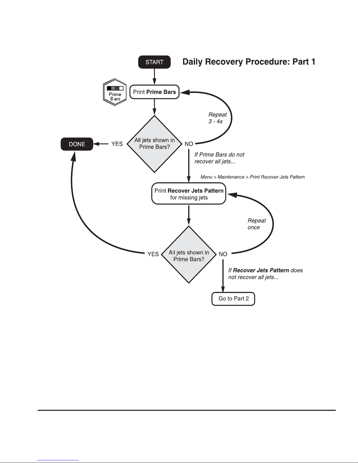
Recover Jets Part 1 9. Print the Prime Bars.
◆ If all jets (indicated by a printed line) are working, the
printer is ready to print.
◆ If there are any missing jets, print the Prime Bars again
three or four times until all jets are working.
10. If any missing jets are present after printing the Prime Bars,
print a Recover Jets Pattern (Menu > Maintenance > Print
Recover Jets Pattern).
This is a special pattern designed to recover missing inkjets.
After printing this pattern, the prime bars are printed again.
◆ If all jets (indicated by a printed line) are working, the
printer is ready to print.
◆ If there are any missing jets, print the Recover Jets Pat-
tern one more time.
1-12 Workflow Overview
Page 25
Workflow Overview 1-13
Page 26

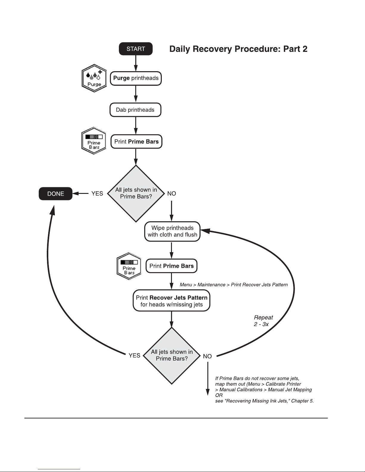
Recover Jets Part 2 11. If any missing jets are observed after printing the Recover Jets
Pattern a second time, Purge the printheads.
From the Front Page, press the Purge key, and purge the colors with missing jets. The control panel prompts you to
remove the parking station so the carriage can be moved to
the left side of the printer for purging.
12. Dab the printheads you purged with a lint-free cloth moistened with Océ IJC700 UV Print Head Flush.
You may wish to wear gloves during this procedure to prevent staining your hands with ink. Do not use a paper towel
or non-lint free cloth, or use a wiping motion, which could
clog the inkjets.
13 . Pr i n t t h e Prime Bars.
◆ If all jets (indicated by a printed line) are working, the
printer is ready to print.
14. If the Prime Bars show any missing jets, dab only the printheads that have missing jets:
◆ Remove the parking station from the end of the printer.
◆ From the Front Page, press the Access Heads key.
◆ Dab or blot the printheads with a lint-free cloth moist-
ened with Océ IJC700 UV Print Head Flush.
◆ Press the Access Heads key again to return the carriage
to the wiping station.
◆ Reinstall the parking station and retaining pin.
15 . Pr i n t th e Prime Bars.
16. Pr i nt the Recover Jets Pattern for those printheads with missing jets.
After printing this pattern, the prime bars are printed again.
◆ If all jets (indicated by a printed line) are working, the
printer is ready to print.
◆ If there are any missing jets, repeat steps 14 through 16
two or three times until all jets are working.
17. If the Prime Bars show any missing jets, map them out using
the Manual Jet Mapping function (Menu > Calibrate Printer >
Manual Calibrations > Manual Jet Mapping).
1-14 Workflow Overview
Page 27

Alternatively, you can attempt to recover the remaining
missing jets. See “Recover Missing Ink Jets” on page 5-7 for
instructions.
Workflow Overview 1-15
Page 28
1-16 Workflow Overview
Page 29

600x300 Printing
The default printing resolution is 600x600 dpi. To print a document at 600x300 dpi:
◆ Configure the RIP to rasterize print jobs at this resolution.
Refer to the RIP documentation for instructions.
◆ Set the printer to Production Quality Normal print mode. In
this mode, the printer will accept print jobs rasterized at
either 600x600 or 600x300 dpi, and print them accordingly.
If the printer receives a 600x300 dpi print job while set to
another print mode, the job will be handled according to the
option selected. See “Selecting a Print Mode” on page 3-5
for instructions.
Workflow Overview 1-17
Page 30

Daily Shutdown 1. DO NOT POWER DOWN THE PRINTER.
The printer will automatically enter a Sleep mode when it has
been idle for a user-defined period of time (see page 2-7 for
details).
If the printer must be shipped or power removed for an
extended period, see “Extended Power Down and Restart” on
page 5-25 for instructions.
1-18 Workflow Overview
Page 31

Parts Overview
12
13
1 2 3 4
14 & 15
17
18
11
5
7
6
8
9
10
14 & 15
19
16
20
21
22
11 a
11 b
23
24
25
26
Fig. 1-1. Major parts of the printer
27
Parts Overview 1-19
Page 32

Index Description
1Encoder strip — allows precise positioning of the print-
head carriage across the length of the platen.
2 Main carriage drive belt — moves the carriage across
the length of the platen.
3Platen — supports the media under the printheads
during printing, warms the media in the print zone,
includes vacuum to hold the media against the platen.
4 Transport chain — supports the ink supply tubes that
carry ink from the ink boxes to the printheads, power,
and electrical signal cables.
5 Printhead carriage — carries the printheads, digital
imaging sensor, and photodiode across the length of
the platen.
Digital image sensor (on carriage, not shown) —
detects the location of printed pixels for precise alignment of the printheads, enables the automatic replacement of poorly-printing inkjets with substitute jets.
Photodiode (on carriage, not shown) — enables the
linearization (calibration) of color transforms without
an external device.
6UV cure lamps — high-intensity lamps that cure the ink
with ultraviolet light.
7Control panel — displays messages and allows control
of certain printer operations. Includes a contrast adjustment lever and audio feedback.
8 Wiping station cover — hinged at the front, remains
closed during printing. Operator opens the cover during a Performance Purge. Can be raised and lowered to
accommodate a wide range of media thicknesses (see
9 Drain valve — empties the wiping station of uncured
ink.
10 Electronics box — contains the printer’s power supply
and control electronics.
11 Pinch rollers (23 places) — grip the media during
loading and printing. The pinch roller adjustment
lever (11a) allows you to adjust the force or release the
pinch rollers to feed rigid cut-sheet media. A media
out sensor (11b) detects whether media is loaded.
1-20 Parts Overview
Page 33

Index Description
12 U V p a r k i n g s t a t io n — shields the operator from excess
exposure to UV light. It must be installed during printing, but may be removed to access the printheads for
cleaning.
13 S t a n d — supports the printer.
14 Casters (four places) — enables easy relocation of the
printer, can be locked in place.
15 Leveling pads (four places) — allows the printer to be
stabilized and leveled for consistent media feeding.
16 Docking station — holds the profilers, one for each
box, that track ink and printhead flush usage, and identify ink characteristics for the RIP.
17 Ready-for-Refill LEDs — an LED illuminates when its
corresponding profiler indicates that the ink box
should be replaced with a full one.
18 Of f-Head System (OHS) — electronics, vacuum (to
maintain negative head pressure), and pressure (for
purging the printheads) that provide ink and printhead
flush for cleaning the printheads.
19 In k bo x es — each box holds ink or printhead flush.
Flexible tubing connects to each box to deliver the contents to the printheads.
20 Standby power switch — places printer in standby
mode (to disconnect from power, disconnect power
cord).
21 UV lamp power supply — provides the UV lamps with
power.
22 Vacuum/Pressure (VP) assembly — provides vacuum
and pressure to the OHS and printheads.
23 Media advance switch — a rocker switch that advances
the media forward or back.
24 Auxiliary 24 volt power jack to VP system — accepts
the supplied 24 volt DC power supply to the VP system,
which can be connected to a user-supplied UPS for
temporary battery backup power or a wall outlet for
temporary power during maintenance that requires the
rest of the printer to be powered down. See Appendix
A, Technical Specifications, for details.
Parts Overview 1-21
Page 34

Index Description
25 Media supply and takeup system — drives and pro-
vides tension to the media supply and takeup spools.
For printing on large rolls of narrow media, the 98-inch
model includes spool support accessories (see
page 3-15).
26 Line conditioner — prevents voltage fluctuations, line
noise, and transient surges from reaching the UV power
supply.
27 Storage hook for light-blocking mat — provides a con-
venient storage space for the light-blocking mat when
not in use for 0.5 inch or thicker rigid media.
28 Input and output roller tables for rigid media —
specially-designed roller tables support rigid media for
precise media advance and best print quality. A second
set of tables can be attached and clamped to the first
set to support longer media. The tables can be easily
connected to and removed from the printer as needed.
28
1-22 Parts Overview
Page 35

Special Features The printer has many advanced features to help you produce the
best printed output with the least effort.
Printheads ◆ Micro-Quad
TM
printheads — sixteen 600 dpi piezoelectric
printheads (four per color).
Ink System ◆ Off-Head System (OHS) — 3 liter bulk ink boxes with profil-
ers supply the printheads. The printer displays an alert when
an ink box should be replaced.
◆ Onboard vacuum/pressure (VP) system — provides vac-
uum to maintain negative printhead pressure, and air pressure to purge the printheads or ink tubes without removing
them from the printer.
Calibration The Advanced Automation Eye uses a high-resolution imaging
sensor, photodiode, and embedded software to align the printheads, detect and replace missing jets, linearize output, and
color profile media.
◆ AutoSet
ing sensor to automatically align printheads bidirectionally
for precise positioning of inkjet pixels, and runs AutoJet.
◆ AutoJet
by locating them and using substitute jets without slowing
printing speed.
◆ AutoTune
vals, for highest quality during unattended printing. Optionally, if unsubstituted non-working jets are found, printing
stops until the problem is corrected.
TM
calibration — uses a high-resolution digital imag-
TM
calibration— compensates for lost or misfiring jets
TM
scheduling — runs AutoJet at user-defined inter-
◆ Automatic color calibration — uses an onboard photodiode
to linearize output over the entire density range (with RIP
support).
◆ Color profiling — with RIP support, the onboard photo-
diode can be used to create custom color profiles.
Special Features 1-23
Page 36

Media Handling ◆ Half-inch head height — the printer can accept rigid sheet-
fed media up to 0.5 inches (12.7 mm) thick. When switching between media less than 0.25 and greater than 0.25
inches thick, three simple adjustments are necessary for print
quality and UV light blocking. See “Loading Rigid Media” on
page 3-27 for instructions.
◆ Media width sensing — automatically detects the width and
position of the media loaded, for precise image placement.
◆ AutoEdge — automatically aids the loading of rigid sheets by
detecting the leading edge.
◆ Rigid media roller tables — specially-designed roller tables
support rigid media for precise media advance and best print
quality. Stabilizer bars ensure stable handling of heavy
media. A second set of tables can be attached and clamped
to the first set to support longer media. The tables can be
easily connected to and removed from the printer as needed.
◆ Steel media spools — the takeup supports up to 7.5 inch
(190 mm) diameter rolls of vinyl media on 3-inch cores. The
supply can also accept 2-inch cores with the supplied 2-inch
collets. On the 98-inch model, spool supports and a reinforcement sleeve support the weight of longer rolls of media
less than 72 inches wide.
◆ Tensioned roll-to-roll media handler — tensioning is auto-
matically maintained on the supply and takeup as the roll
diameters change during printing. Optionally, the supply or
takeup motors can be idled during printing. In roll-fed
mode, the supply must be loaded, but the media can optionally be left off the takeup.
1-24 Special Features
Page 37

Performance and
Ease-of-Use
◆ Media Wizard — stores and recalls a set of operating param-
eters by media type and print mode, for optimal printing
performance. Includes a set of predefined settings for standard media; user may add settings for other media.
◆ Speed/quality print modes — provided to meet speed and
quality requirements.
◆ Edge-to-edge printing — margins on rigid media can be set
to zero for edge-to-edge printing, providing “full bleed”
prints without trimming.
◆ Fine Text Mode — prints at half the normal head speed to
improve the output quality of fine text and line art.
◆ Sharp Edge Mode — adds additional print passes and
reduces print speed by 20% to reduce visible ink overspray
at the edges of objects.
◆ Simplified control panel interface — Front Page screen pre-
sents frequently-used functions, with recommended preset
configurations. A menu provides access to less-frequently
used functions and troubleshooting help.
◆ User assistance — control panel features online help, interac-
tive procedures, and diagnostics to assist the user “on-thefly,” reducing training and troubleshooting time.
◆ Integrated Warning/Action system — the ATTN (Atten-
tion) key blinks on the control panel when the printer
detects an error condition, potential error condition, or when
you make a change that suggests recalibration or other
action to ensure best print quality.
Special Features 1-25
Page 38

1-26 Special Features
Page 39

CHAPTER 2
Using the Control Panel
This chapter describes the functions of the control panel.
◆ Overview (page 2-2)
◆ Front Page (page 2-4)
◆ Navigation Keys (page 2-9)
◆ Menu (page 2-10)
◆ Menu Tree (page 2-17)
Using the Control Panel 2-1
Page 40

Overview The touch-screen control panel shows you the printer’s current
status, and enables you to interact with the printer when changing media and ink, respond to an error condition, or configure
options. There are three main control panel screens:
◆ Ready (Status) Screen
◆ Front Page
◆ Menu
Ready Screen When you press the Online/Offline button from the Front Page
screen, the printer goes online and the Ready screen appears.
The Ready screen displays the current status of the printer and
any currently printing job. It displays when the printer is online
(communicating with the print server) and either ready to print
or printing.
Front Page When you press the Online/Offline button from the Ready
Menu When you press the Menu key on the Front Page screen, the
2-2 Overview
Fig. 2-1 Ready screen
Screen, the printer goes offline and the Front Page screen
appears. This screen is the top level of the printer’s menu system. It provides access to the most frequently-used offline functions. For details, see “Front Page” on page 2-4.
Menu appears. The Menu provides access to advanced configuration options. For details, see “Menu” on page 2-10.
Page 41

User Assistance The control panel provides various forms of online user
assistance:
The ? button provides an explanation of the current function,
with some guidance for what to do next.
The ATTN (Attention) key blinks on the control panel when the
printer detects an error condition, potential error condition, or
when you make a change that suggests recalibration or other
action to ensure best print quality. There are two types of ATTN
messages:
◆ Actions — the printer has detected an error condition that
stopped printing or will prevent printing from starting. You
must correct the error before the printer will be ready to
print.
◆ Warnings — the printer has detected a condition that, if left
unaddressed, could result in substandard prints or a condition that will require an action before printing can continue.
Any action on your part is optional. Printing is not interrupted for a Warning message.
When the printer issues one of these messages, the ATTN key
will blink, and an alert beep will sound (unless disabled, see
page 2-13). Press the ATTN key to display a list of message titles,
and select a title to display a detailed cause-and-recovery screen.
The table beginning on page B-10 also lists these messages and
recovery procedures.
If you choose to not correct a Warning condition and resume
printing, the ATTN key will remain displayed, but will not blink
until the printer issues a new Warning or Action message. The
messages can be dismissed by correcting the condition, or by
pressing the applicable key on the detail screen.
Tip
To disable the ATTN key, see page 2-13 for instructions on choosing Expert mode. Expert mode routes
most messages to an Actions & Warnings menu
option.
Overview 2-3
Page 42

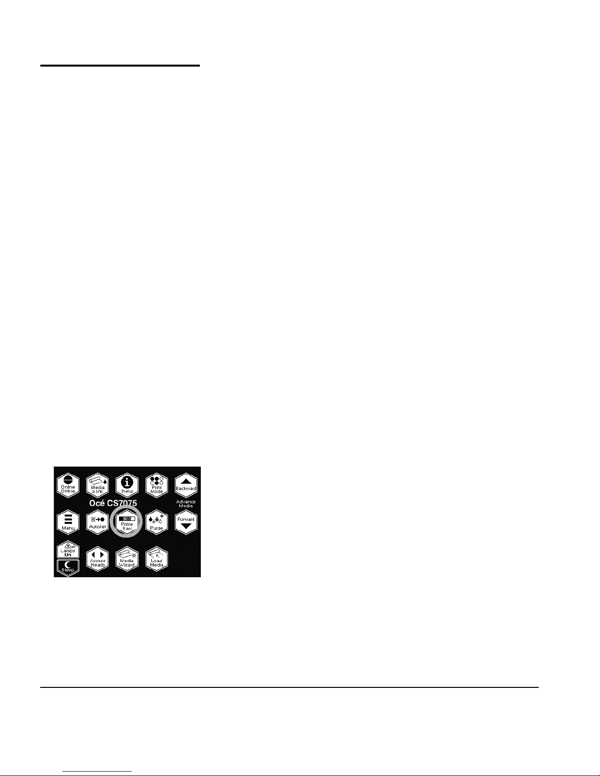
Front Page The Front Page provides access to the most frequently-used
printing and maintenance functions. For advanced configuration options, press the Menu key (see “Menu” on page 2-10 for
instructions).
Fig. 2-2. Front Page
◆ Printer Name — displays the name of the printer as defined
on the print server or under the menu at Printer Settings >
Printer Name.
◆ Online/Offline — returns the printer to the Ready screen,
when it is online and ready to receive print jobs.
2-4 Front Page
Page 43

◆ Media & Ink — displays a listing of the media and ink cur-
rently installed in the printer. Press the and keys to
highlight “Media” or one of the inks, then press (Proceed) to display information about the selection. From this
screen, you can press the and keys to scroll between
screens. Press (Proceed) to return to the list, then
(Menu Out) to display the Front Page screen.
Front Page 2-5
Fig. 2-3. Media Info, Ink Info screens
Page 44

◆ Status — displays system parameters and the status of all
user-configurable options. Press the and keys to scroll
between pages. To change an option, go to the Printer Configuration section of the menu.
Fig. 2-4. Status page 1
◆ Print Mode — sets print quality mode. See “Selecting a Print
Mode” on page 3-5 for instructions.
◆ Advance Media — press the key to advance the media for-
ward. When you press and hold the key, the media moves
faster. Press the key to reverse the media back onto the
supply spool. When you press and hold the key, the media
moves faster. You can also press the Media Advance rocker
switch, located between the inks and the platen, to move
the media in either direction.
◆ Menu — displays the complete printer menu for access to
advanced configuration options (see “Menu” on page 2-10
for instructions).
◆ AutoJet — detects deflected and non-firing jets, and substi-
tutes working jets for them (in Production and High Quality
modes, not available in Billboard mode.).
◆ Prime Bars — fires all jets by drawing a set of lines called
prime bars. This is a good way to inspect and prepare the
jets for printing after they have been idle (see “Print Prime
Bars” on page 3-9). You can also print a similar pattern
called Print Jet-Out Lines, which shows which jets have been
detected and replaced by AutoJet (see page 2-11 for details).
2-6 Front Page
Page 45

◆ Purge — purges the printheads on the left side of the printer,
to help recover missing jets. Follow a purge with a manual
dab or blot of the printheads (do not wipe) with a lint-free
cloth.
◆ Lamps On/Off — allows you to manually power on or off the
lamps, instead of waiting for automatic operation.
◆ Sleep/Wake — Sleep detensions the takeup system (roll-fed
media), and powers down the UV lamps, printheads, carriage, and media drive motors, but maintains vacuum to the
printheads to prevent ink leakage. Wake tensions the takeup
system and powers up the printer components. The printer
goes into sleep mode automatically after 30 minutes, and
“wakes” automatically when a print job is received or a
printer operation is performed from the control panel.
In Sleep Mode, the carriage moves 0.25 inches (6 mm) once
per hour for three hours, then moves in the other direction
for three hours, and repeats this sequence until the printer is
restored from Sleep Mode. This prevents the formation of a
flat spot on the carriage bearings (wheels) when the printer
is in Sleep Mode for over 24 hours.
Caution
If printhead vacuum is lost during Sleep Mode, ink
will begin to seep from the printheads.
To prevent ink leakage during an unexpected power
outage, Océ strongly recommends using the vacuum/pressure system’s 24 volt auxiliary power supply
and connecting it to an uninterruptable power supply (UPS). Affordable and reliable UPS units are available with 100-240 VAC, 50/60 Hz, minimum of 15
watts. See Appendix A for details. It is not necessary
to connect the entire printer to a UPS, only the vacuum/pressure system needs to be connected to
avoid ink seepage.
◆ Access Heads — moves the printhead carriage out from the
service station to the opposite end of the printer. This is the
same functionality as the Access Printheads option on the
Maintenance menu. The UV parking station must be removed first to avoid the possibility of the carriage striking it.
◆ Media Wizard — provides direct access to the printing
parameters stored for the currently loaded media (see
“Media Wizard” on page 3-41 for details).
Front Page 2-7
◆ Load (visible when the supply and takeup are unloaded) —
loads roll-fed or sheet-fed media. See “Loading Roll-Fed
Page 46

Media” on page 3-14, or “Loading Rigid Media” on page 327 for instructions.
◆ Unload (visible when the supply and takeup are loaded) —
detensions and enables you to unload the supply and takeup
system. See “Unloading and Cutting Roll-Fed Media” on
page 3-21 for instructions.
◆ Reload — enables you to load another roll or sheet of the
previously printed media with the same settings, without
stepping through the media load process.
◆ AT TN (Attention)— blinks on the control panel when the
printer detects an error condition, potential error condition,
or when you make a change that requires recalibration or
other action to ensure best print quality. See “User Assistance” on page 2-3 for details.
2-8 Front Page
Page 47

Navigation Keys The following table shows you how to move through the menu
system and perform printer control functions.
Key Description
Display Menu — displays the printer menu.
Menu In — selects the highlighted menu option.
Menu Up/Down — moves the menu highlight up and
down the menu.
Menu Top/Bottom — moves the menu highlight to the
top or bottom for the menu.
Menu Out — moves to the next higher menu in the
hierarchy.
Back/Forward — moves between pages or screens, or
selects between other options.
Proceed — initiates the selected function.
Help — displays a summary description of the high-
lighted menu options.
Pause/Resume — pauses or resumes printing during a
calibration.
Cancel — cancels the current menu function or choice.
Yes/No — indicates a Yes or No.
Navigation Keys 2-9
Continue (error screen) — proceeds to the next step in
a troubleshooting dialog.
Ignore (error screen) — specifies “ignore” in a trouble-
shooting dialog.
Retry (error screen) — specifies “retry” in a trouble-
shooting dialog.
Reboot Printer (error screen) — specifies “restart
printer” in a troubleshooting dialog.
Information (error screen) — displays further informa-
tion about the error.
Page 48

Menu The menu has these main sections:
◆ Calibrate Printer (see below)
◆ Printer Settings (page 2-11)
◆ Maintenance (page 2-15)
◆ Service Printer (page 2-16)
◆ User Diagnostics (page 2-16)
◆ Warnings & Actions (page 2-16), shown in Expert Messages
Mode only
◆ Print Menu Tree (page 2-16)
This section explains each of the functions on the printer menu.
See “Menu Tree” on page 2-17 for a listing of all menu options.
Calibrate Printer For instructions on using these options, see Chapter 4, Calibrat-
ing the Printer.
◆ Auto Calibrations — see “Auto Calibrations” on page 4-6 for
instructions.
◆ Auto Bidi Calibration — ensures that every working jet
fires a pixel at precisely the same location, in both directions of travel
◆ Auto H2H Calibration — aligns the printheads relative to
each other
◆ AutoJet Calibration — locates and substitutes missing jets
for working jets
◆ Full AutoSet — runs AutoJet, AutoBiDi, and AutoH2H in
sequence
2-10 Menu
Page 49

◆ Manual Calibrations — allows you to calibrate the printer
visually, without the printer’s digital imaging sensor. Inaccurate judgments by the operator during these tests could
result in substandard output. See “Manual Calibrations” on
page 4-8 for instructions.
◆ Media Feed
◆ Manual Bidi Registration
◆ Manual X Head Registration
◆ Manual Jet Mapping — the manual version of AutoJet
◆ Jet Status Lines — prints the Manual Jet Mapping pat-
tern without running the calibration
◆ Print Jet-Out Lines — prints a version of the prime bars
(see page page 2-6), in which missing jets that are
replaced are marked with a black square.
◆ Default Registration Data
◆ AutoTune (roll-fed media only) — schedules jet maintenance
to run automatically after a certain number of prints have
printed. See “AutoTune” on page 4-4 for instructions.
◆ Calibration Summary — prints summary information with
the AutoSet calibration test patterns, or transmits registration or jet data to a log file on the print server. See “Calibration Summary” on page 4-25 for details.
◆ Configure for Profile Creation (cut sheet printing only) —
causes all calibration prints to print on the same cut sheet,
rather than ejecting the sheet after each calibration print.
Automatically disabled after all calibration prints are finished, when a print job is received from the RIP, or when rollfed media is loaded. The user can specify a dry time delay
after which the linearization will begin.
Printer Settings Printer Settings enables you to set many options that control
how the printer operates. Settings saved by the Media Wizard are
indicated by
MEDIA WIZARD ◆ Takeup Tension — adjusts the media takeup tension, which
is required for proper media feeding. Insufficient takeup tension could result in inaccurate media feed and media buckling.
MEDIA WIZARD ◆ Supply Tension (CS7075) — adjusts the media supply ten-
sion, which is required for proper media feeding. The lowest
(“idle”) tension is best for most media. (The CS7100
tension is always idle.)
MEDIA WIZARD in the margin.
supply
Menu 2-11
Page 50

◆ Supply Out Detection (CS7100) — reports when the supply
spool stops rotating, indicating that there is no more media.
This setting is also available on the CS7075 when the Supply
Tension option is set to idle.
MEDIA WIZARD ◆ Platen Vacuum Control — turns on the vacuum fans, then
allows you to raise or lower the fan speed. Raise the speed if
the media is rising off the platen, lower the speed if the
media is buckling or wrinkling. Turn off the vacuum for lightweight media such as paper or fabrics.
MEDIA WIZARD ◆ Printing Delay — slows throughput (media advance speed)
to allow the media to cool between passes, preventing curling of rigid media.
MEDIA WIZARD ◆ Media Out Sensor — enables you to disable the media out
sensor if it is malfunctioning, or enable it after it has been
replaced.
◆ Gutter Settings — determines the appearance of the top and
side gutters:
◆ Top Gutters — allows you to turn On or Of f the gutter
data at the top edge of the print, which shows the job
name, ink, media, date and time printed, print mode,
lamps setting, printer, embedded software version, plus
write-in blanks for other data.
◆ Side Gutters — sets the side gutter pattern to Narrow,
Medium, or Wide sizes, or turns them Off. Side gutter
patterns help keep the inkjets open by firing ink through
them in a pattern outside the printed image area.
◆ Margin Settings
◆ Space Between Prints (roll-fed) — sets the blank space
between print jobs, between 0 and 10 inches (25 cm).
◆ Right and Left Margin — sets the amount of blank space
for the right and left margins, between 0.25 and 5
inches (6-127 mm) for roll-fed media, and between 0
and 5 inches (0-127 mm) for cut-sheed media.
When you set the right and left margins to zero (edgeto-edge printing on cut-sheet media), the printer
prompts you for an Overprint value. This is the distance
beyond the edge of the media to print, to help avoid a
blank strip if the sheet is slightly skewed, not perfectly
rectangular, or other error is present. Apply tape to the
platen at the edge of the media to catch the overprinted
ink. For further information on edge-to-edge printing,
see “Edge-to-Edge Printing” on page 3-35.
◆ Leading Margin — defines the margin on the leading
edge of cut-sheet media.
2-12 Menu
Page 51

◆ Trailing Margin — defines the margins on the trailing
edge of cut-sheet media.
Note
If you load roll-fed media, the printer automatically
resets the margins to 0.25 inches (6 mm).
◆ Measure Media Type — for cut-sheet media, you can choose
one of three levels of precision for finding the left, right, and
front edges of the media.
◆ Minimal — measures the width of the media once, and
finds the front right edge
◆ Standard — measures the width of the media once, and
finds the right and left front edges to estimate skew
◆ Maximal — measures the width of the media in two
places to estimate skew
Choose Minimal for fastest throughput, Maximal for greatest
precision and skew detection when printing edge-to-edge.
◆ Quality Check — determines how AutoTune errors are han-
dled (see page 4-5).
◆ Print Position — when the printed image does not span the
entire width of the media, positions the printed image flush
right (nearest the control panel), flush left, or centered on
the media.
MEDIA WIZARD ◆ Stif f Roll-Fed Media Handling — when enabled, detensions
then retensions the takeup system before every print job, for
more accurate feeding of adhesive-backed and other stiffer
roll-fed media types.
◆ Sleep Wait Time — sets the period of time to wait for a print
job before going into Sleep mode (see page 2-7).
◆ Expert/Novice Messages — Novice mode presents an ATTN
(Attention) key with Warnings (alerts that do not prohibit
printing) and Actions (conditions that require user intervention before printing can proceed). Expert mode presents
Actions only, presents fewer “press Proceed” prompts after
an Action has been addressed. The default is Novice mode.
When in Expert mode, active Warnings and Actions can be
displayed by selecting Warnings & Actions from the menu,
since Warnings will not cause the ATTN key to appear in
Expert mode. See “User Assistance” on page 2-3 for further
information about Actions and Warnings.
◆ Audible Alarm — enables and disables the audible alarm
beep that sounds with Warning and Action messages.
Menu 2-13
Page 52

◆ Localization — sets English or Metric units of measure, and
time and date formats, for data displayed by the control
panel.
◆ Head Height — moves the printhead carriage over the platen
so you can adjust the head height. See “Set the Printhead
Height” on page 5-11 for instructions.
◆ Wiping Position — allows you to center the carriage over the
service station for best wiping.
◆ Automatic Eject (cut sheet printing only) — when enabled,
the sheet is automatically ejected at the end of the print job.
When disabled, the next job(s) will print on the same sheet
until there is no more room to print.
◆ Low Ink Warning — defines the amount of ink remaining in
the ink box supply at which the printer will display a “low
ink” message on the control panel.
◆ UV Lamps Idle Time — sets the amount of time the lamps
will stay on after printing before they are automatically
turned off by the printer. The idle time can be set from 1 to
10 minutes. Increase the idle time if you are printing several
jobs and waiting for the lamps to warm up between prints,
decrease the idle time if printing single jobs.
◆ UV Lamps Warm-Up Time — if both UV lamps have not
warmed up completely when the first print begins printing,
printing anomolies are likely to occur due to insufficientlycured ink. This option allows you to extend the warm-up
period to ensure that both lamps have warmed up enough
to cure the ink completely. The current warm-up period is
displayed on the Front Page printer status pages.
◆ Printer Name — displays a keypad to change the printer
name displayed on the control panel and RIP.
◆ Restore All Defaults — restores all Printer Configuration set-
tings to their factory default values, and zeroes all registration data. After running this option, all calibration values
must be reestablished by running AutoSet or manual calibrations.
2-14 Menu
Page 53

Maintenance ◆ Access Printheads — moves the carriage to the left side of
the printer. Remove the UV light shield before selecting this
option, to avoid the possibility of the carriage striking it.
◆ Perform An Air Purge — purges the printheads with air.
Select Standard to clear most jet-outs, or Performance to
clear stubborn jet-outs (expels more ink).
◆ Print Recover Jets Pattern — prints a special pattern
designed to recover missing inkjets. After printing this pattern, the prime bars are printed.
◆ Print Jet-Out Lines — prints a version of the prime bars (see
page 2-6), in which missing jets that are replaced are
marked with a black square.
◆ Print Media Skew Lines — prints a swath of parallel lines
across the width of the media, in alternating directions, continuously until you stop the print. If the swaths are not parallel to each other, the media is skewed (not feeding straight).
If there is a noticeable space between swaths, or if they overlap, the media advance should be calibrated.
◆ Reset Reservoir Filters — after you replace the filters, select
this option to reset the ink counts to zero. See “Replace Ink
Filters” on page 5-16 for instructions.
◆ Reset UV Lamp Hours — resets the lamp’s elapsed operating
time clock to zero. The printer displays a warning message
when the UV lamps have been in service for a certain period.
They should be replaced when they are no longer curing the
ink. To view the total operating time for each lamp, press the
Status key on the Front Page, and advance to the page
where this is listed.
◆ Respool Media — respools media from the supply directly to
the takeup (in either direction) without passing over the
platen.
◆ Clean Grit Rollers — advances the grit rollers continuously so
they can be cleaned (with no media loaded).
◆ Printheads Procedures — see “Printhead Procedures” on
page 5-24, for instructions on using the following options:
◆ Load Ink in All Heads — fills empty printheads with ink.
◆ Fill Heads with Ink — fills the printheads with ink.
◆ Empty Heads (Fill With Air) — fills the printheads with
air.
Menu 2-15
Page 54

Service Printer These tests are for factory, service, and technical support use.
User Diagnostics User Diagnostics presents an interactive troubleshooting pro-
gram to diagnose problems before calling Océ Display Graphics
Systems Technical Services. It walks you through a series of tests
and checks for certain printer functions. The printer asks you to
make observations or run simple tests to help it diagnose problems and suggest corrective actions. It has the following sections:
◆ Printhead Jet Statistics
◆ VideoNet Status
◆ VideoNet Connection
◆ Carriage Motion
◆ Calibration
◆ Vacuum Pressure
◆ Warnings and Actions List — table of all actions and warn-
ings with cause and recovery. This is an abbreviated version
of the table “Action and Warning Messages” on page B-9.
◆ Error History
◆ Log Error History
Warnings & Actions When in Expert mode, any current Warning, Change, and
Action messages can be displayed by selecting Warnings &
Actions from the menu. When in Novice mode, press the ATTN
icon on the Front Page screen to view these messages.
See “User Assistance” on page 2-3 for further information about
Actions and Warnings, and the table beginning on page B-9 for a
list of recovery procedures.
See page 2-13 for a description of the Expert/Novice Messages
mode.
Print Menu Tree This option prints all of the menu options in a hierarchical tree
format.
2-16 Menu
Page 55

Menu Tree
Front Page
Online/Offline
Show
Menu
AutoJet
Lamps On/Off
Sleep/Wake
Media & Ink
Status
Access Heads
Printer
Status
Media
Wizard
Select
Print Mode
Load/
Unload/
Reload
Advance
Media
Print
Prime Bars
Purge
Printheads
Attention
Menu Tree 2-17
Page 56

Menu This menu tree reflects version 1.34 of the embedded printer software.
Refer to the Release Notes for more recent versions. Options shown in
italics are dynamically hidden depending on the printer mode.
Calibrate Printer
Auto Calibrations
AutoBidi Calibration
AutoH2H Calibration
AutoJet Calibration
Full AutoSet
Manual Calibrations
Media Feed
Manual Bidi Registration
Manual X Head Registration
Manual Jet Mapping
Jet Status Lines
Print Jet-Out Lines
Default Registration Data
AutoTune (Roll-Fed media only)
Calibration Summary
AutoSet Summary
Log Head Registration Data
Log Jet Data
Configure for Profile Creation
(Cut-Sheet media only)
Printer Settings
Takeup Tension
Supply Tension (CS7075)
Supply Out Detection (CS7100)
Platen Vacuum Control
Printing Delay
Media Out Sensor
Gutter Settings
Top Gut ters
Side Gutters
Margin Settings
Space Between Prints
Right and Left Margin
Leading Margin
Trailing Margin
Media Measure Type
Quality Check
Print Position
Stiff Roll-Fed Media Handling
Sleep Wait Time
Expert/Novice Messages
Audible Alarm
Localization (was “Units”)
Units of Measure
Time Format
Date Format
Head Height
Wiping Position
Automatic Eject
Low Ink Warning
UV Lamps Idle Time
UV Lamps Warm-Up Time
Printer Name
Restore All Defaults
Maintenance
Access Printheads
Perform An Air Purge
Print Recover Jets Pattern
Print Jet-Out Lines
Print Media Skew Lines
Reset Resevoir Filters
Reset UV Lamp Hours
Respool Media
Clean Grit Rollers
Printheads Procedures
Load Ink In All Heads
Fill Heads with Ink
Empty Heads (Fill with Air)
Service Printer
Device Tests
Print Tests
Ink System Tests
Home Head
Measure Media Width
Tension Supply & Takeup
Measure Platen Width
Zero Platen Width
Printhead Y Calibration
Image Sensor Calibration
Media Thickness Calibration
Configure Warning Attns
Drip-Through Service Cover
Carriage Control
Print Info Pages
User Diagnostics
Printhead Jet Statistics
VideoNet Status
VideoNet Connection
Carriage Motion
Calibration
Vacuum Pressure
Warnings and Actions List
Error History
Log Error History
Warnings & Actions (Expert Mode only)
Print Menu Tree
2-18 Menu Tree
Page 57

CHAPTER 3
Ink and Media
This chapter describes how to use ink and media with the printer:
◆ Ink
◆ Ink System Overview (page 3-2)
◆ UV Lamp Overview (page 3-3)
◆ Selecting a Print Mode (page 3-5)
◆ Checking Jet Health (page 3-9)
◆ Loading Ink (page 3-11)
◆ Media
◆ Loading Roll-Fed Media (page 3-14)
◆ Unloading and Cutting Roll-Fed Media (page 3-21)
◆ Respooling Media (page 3-23)
◆ Printing Tips (page 3-25)
Ink and Media 3-1
◆ Using the Media Tables (page 3-26)
◆ Loading Rigid Media (page 3-27)
◆ Unloading and Reloading Rigid Media (page 3-34)
◆ Media Wizard (page 3-41)
Page 58

Ink System Overview The printer’s ink system consists of the following components:
◆ Ink boxes — bag-in-box supply of UV cure ink, suitable for
both flexible and rigid media applications.
Note
◆ Océ IJC700 UV Print Head Flush — used to moisten the lint-
free cloth or wiper tool for cleaning the printheads, also in
automated flushing of the printheads. It has no properties
that work against the ink to soften or reliquify cured ink, or
any other similar cleaning properties. It does not react with
the ink, making it suitable for use as a lubricating agent for
cleaning.
Caution
◆ Profilers — provided with each ink box, they contain infor-
mation about the ink and must be installed together with
their corresponding box. Profiler data are used to track ink
levels, and to help ensure optimal output quality and compatibility with printer components.
Unlike other inks used in wide format printing, UV
cure ink has a limited shelf life. Plan to rotate your
ink stock and use it promptly by the date printed on
the ink box.
Use only genuine Océ IJC700 UV Curable Inks and
Océ IJC700 UV Print Head Flush in the printer. Use of
any other inks or cleaning fluids COULD DAMAGE
THE PRINTER AND WILL VOID THE WARRANTY.
◆ LEDs — the LED next to each profiler illuminates when the
box is almost empty, to alert the operator to exchange the
box for a full one. The LED above a box will also blink when
there is an Attention message associated with that color.
◆ Ink tubes — carry ink to the printheads, they are opaque to
prevent ink curing before printing.
◆ Printheads — permanent piezo-based printheads.
◆ Vacuum/Pressure (VP) System — provides vacuum to main-
tain negative pressure at the printheads, and pressure to
purge the ink tubes and printheads.
◆ UV lamps — provide the high-intensity ultraviolet light
required to cure the ink.
3-2 Ink System Overview
Page 59

UV Lamp Overview The printer’s two UV lamps (on the left and right sides of the
printhead carriage) emit the high-intensity ultraviolet light that
is necessary to cure the UV ink.
The lamps require a separate power supply from the printer, to
light the lamps and ensure adequate curing. They have a limited
life, during which the amount of UV light emitted slowly
decreases, eventually reaching a level that will no longer cure
the ink. There are measures you can take to extend the service
life of the lamps, but they will eventually have to be replaced.
You should be aware of the following characteristics of these
lamps when operating the printer:
WARNING
VORSICHT UV Licht hoher Intensität. Bitte vermeiden Sie es,
◆ UV light exposure — the printer is designed with shields,
louvers, and other features to protect the operator from
exposing the eyes and skin to high levels of UV radiation. The
printer must be operated with the UV parking station
installed. Do not look directly at the UV light.
◆ High/low lamp operation — the UV lamps are operated at
high intensity only when curing the ink. When the carriage is
not directly over the media, the lamps are switched to a
lower intensity.
◆ Warm-up/cool down cycle — the UV lamps take about one
minute to warm up to operating temperature, and about
three minutes to cool down fully. After printing, the lamps
must fully complete their controlled cool-down cycle before
warming up again for the next print job (for a total elapsed
time of about four minutes).
UV light hazard. The UV parking station must be
installed during printing. Excess exposure to highintensity UV light can result in photokeratitis (also
known as snowblindness or welder’s flash). AVOID
LOOKING DIRECTLY AT THE UV LAMPS.
direkt in die Lampen zu schauen.
UV Lamp Overview 3-3
To save time, you can manually switch on or off the lamps
on the Front Page screen of the control panel (see “Front
Page” on page 2-4).
Page 60

Caution
Do not switch off the UV lamp power supply
unless the lamps have fully completed their controlled cool-down cycle (with fans and heat extrac-
tion). Removing power from hot lamps can result in
overheating and permanent damage. If sudden
removal of power occurs, contact Océ Display Graphics Systems Technical Services before starting the
printer again.
◆ Lamp replacement — the UV lamps will gradually lose their
intensity and therefore their ability to cure the ink. See
“Replacing UV Lamp Bulbs” on page 5-20 or the instructions included with replacement parts for details.
◆ Unidirectional printing — when printing for long periods in
one direction (unidirectionally), the curing ability of the
lamps will become unbalanced, which could result in insufficient curing or printing anomolies. To avoid this, occasionally switch between Unidirectional Left and Unidirectional
Right printing (see “Selecting a Print Mode” on page 3-5).
3-4 UV Lamp Overview
Page 61

Selecting a Print Mode The printer can print in several different modes for the combi-
nation of quality, resolution, and speed that you require.
Maximum Speed
(bidirectional printing)
Mode
Billboard Quality 400 ft² (37.2 m²)/ hour None
Production Quality
with 600x600 dpi jobs
Normal 200 ft² (18.6 m²)/ hour
Fine Text 100 ft² (9.3 m²)/ hour
Sharp Edge 160 ft² (14.9 m²)/ hour
with 600x300 dpi jobs
(requires 600x300-specific color
profiles and file from RIP)
High Quality
Normal 100 ft² (9.3 m²)/ hour
Fine Text 50 ft² (4.6 m²)/ hour
Sharp Edge 80 ft² (7.4 m²)/ hour
@ 72 inches wide
400 ft² (37.2 m²)/ hour
Jet
Replacement
Standard
Maximum
1. On the Front Page screen of the control panel, press the Print
Mode key.
The print mode menu appears, with these options
:
◆ Billboard Quality
◆ Production Quality
◆ High Quality
Jet replacement refers to the printer’s ability to locate and
replace inkjets that are clogged or misfiring. High Quality
mode has the best jet replacement, Billboard Quality mode
has the highest speed.
2. Press the and and keys to highlight a print mode.
3. Press the
(Set) key to select the print mode.
A menu appears with these options:
◆ Bidirectional
◆ Unidirectional Left
◆ Unidirectional Right
Selecting a Print Mode 3-5
Page 62

The printer can print in both directions (bidirectional) or in
one direction only (unidirectional). Unidirectional printing
can occur in either direction. Printing occurs at about half
the speed of the corresponding bidirectional print mode.
Unidirectional printing eliminates the bidirectional misalignment that occurs when printing on media that is not
perfectly flat.
4. Press the and and keys to highlight a direction.
5. Press the
In Production and High Quality modes, a menu appears
with these options:
◆ Normal — prints at full speed.
◆ Sharp Edge — improves the appearance at the edges of
◆ Fine Text — prints at half the normal head speed to
Caution
(Set) key to select the direction.
larger text, colored borders, graphics, and images by
directing the inkjet overspray into the printed area. This
mode requires an additional print pass than Normal
mode.
improve the output quality of fine text and line art by
eliminating overspray.
Printing in Fine Text mode, which prints at 50% of
the speed of the "normal" Production and High
Quality modes, may expose the media to excessive
heat from the UV lamps, which could result in bowing of the center of the medi, and possible contact
with the printheads. Thinner rigid media such as
fluted polypropylene (Coroplast) are susceptible. To
avoid warping, set a media delay in Printer Settings
> Printing Delay, or in a custom Media Wizard
parameter set for Fine Text printing.
3-6 Selecting a Print Mode
This could also be an issue with Sharp Edge printing,
although this mode prints at 80% speed, so it is less
susceptible to excessive heat buildup.
6. Press the and and keys to highlight an option.
7. Press the
In Production Quality Normal mode, the printer will accept
and print jobs rasterized at either 600x600 dpi or 600x300
dpi.
(Set) key to select the option.
Page 63

In all other modes, 600x300 dpi printing is not supported.
When these modes are selected, the 600x300 handling
options appear:
◆ Prompt with Options — the control panel will ask
whether to print the job in Production Quality mode, or
to cancel the job.
◆ Use Production Quality — the job will be automatically
printed in Production Quality mode.
◆ Cancel — the job will be automatically canceled.
To print at 600x300 dpi, set the RIP to rasterize (RIP) print
jobs at this resolution before sending them to the printer. If
the printer is set to print in Billboard Quality or High Quality, the job will be handled as selected at the control panel.
8. Press the and and keys to highlight a 600x300 dpi Job
Handling option.
9. Press the
(Set) key to select the option.
The UV lamps settings appear.
10. Select a UV lamps setting.
When you select a bidirectional print mode, select one of
the following settings:
Setting Leading Lamp Trailing Lamp
High High High
Medium High Low
Low Low Low
Off Off Off
Selecting a Print Mode 3-7
Page 64

When you select a unidirectional mode, select one of the
following settings:
Setting Leading Lamp Trailing Lamp
High High High
Medium High Low
Low Low Low
Leading High High Off
Leading Low Low Off
Trailing High Off High
Trailing Low Off Low
Off Off Off
◆ For standard media listed in the Media Wizard, leave the
lamp settings at their default values, at least at first.
◆ Faster print modes require higher lamp settings to
ensure sufficient curing.
◆ If the ink is not curing, increase the setting. The lamps
will gradually lose curing effectiveness, so increasing the
setting may eventually become necessary. (For infomation about UV lamp life, see “Replacing UV Lamp Bulbs”
on page 5-20.)
◆ If the media is wrinkling or warping from the heat of the
lamps, lower the setting.
◆ Use caution when turning off one of the lamps in the
unidirectional modes. If the difference in total operating
time between the lamps becomes significant, visible
print anomolies may result. To prevent this or rebalance
the hours, alternate printing directions between Unidirectional Left and Unidirectional Right.
◆ Do not select the Off setting unless necessary for trou-
bleshooting or maintenance. The ink will not cure if at
least one of the lamps is not on during printing.
3-8 Selecting a Print Mode
Page 65

Checking Jet Health When AutoJet detects a missing jet, it attempts to replace it with
a working jet on the same or another printhead (in Production
and High Quality modes). In this way, printing occurs with all
jets for maximum quality.
When you notice a decrease in print quality, one or more inkjets
may be clogged. To recover clogged jets:
1. Print a Prime Bars pattern to determine whether there are
any missing jets (see below).
2. Run AutoJet (page 4-3) or Manual Jet Mapping (page 4-18).
3. If there are any missing jets, Print Jet-Out Lines (see below).
Repeat this process until all jets are working or substituted for
another jet.
Print Prime Bars 1. From the control panel Front Page screen, press the Prime
Bars key.
The control panel displays a prompt asking you to enter the
total width of the prime bar pattern you wish to print.
2. Enter a width for the prime bar pattern by pressing the
and keys.
3. Press the (Proceed) key to continue.
The printer prints the prime bar pattern. The prime bars will
show correctly working jets with a solid line, and missing
jets with no line.
Map Out Missing Jets If the Prime Bars (above) reveal a blank lines, the corresponding
jets should be mapped out. For instructions, see “AutoJet” on
page 4-3 or “Manual Jet Mapping” on page 4-18. When all missing jets have been substituted, printed output will appear as if
all jets are working.
Checking Jet Health 3-9
Page 66

Print Jet-Out Lines
1. From the control panel Front Page screen, press the
(Menu) key.
2. Press the
3. Press the (Menu In) key.
4. Press
5. Press the (Menu In) key.
The Jet-Out Lines pattern prints. Substituted jets are marked
with a black square.
key to highlight Maintenance.
to highlight Print Jet-Out Lines.
3-10 Checking Jet Health
Page 67

Loading Ink
When to Load Ink The amount of ink in the ink box is tracked by the printer soft-
ware and recorded on its corresponding profiler. When the ink
box is almost empty, the LED above the corresponding profiler
will blink. You should replace the ink box with a full ink box of
the same color ink as soon as possible. The status of each ink
box and profiler is indicated by the LEDs as follows:
◆ Off — OK
◆ Slow Blink — profiler is being verified after insertion
◆ Fast Blink — low ink warning (300 ml remaining, amount
can be changed by the user)
◆ On — ink system action (ink empty, ink pump failure, pro-
filer error, or other), see control panel
Unloading an Empty Ink
Box
1. Remove the profiler.
2. Lift the box out of its holder and turn the box upside down so
the ink tube is pointing up.
3. Push the button at the end of the ink tube connector and disengage the tube from the ink box.
4. Remove and dispose of the ink box (refer to the MSDS for
proper disposal procedures).
Loading a Full Ink Box 1. Open the new ink box and locate the supply connector.
Loading Ink 3-11
Fig. 3-1. Ink box with supply connector
Page 68

2. Connect the ink supply tube to the ink box.
Grasp and squeeze the ink tube connector as shown, engage
the connector to the ink box, and release the connector.
Ensure that the connectors are firmly engaged before proceeding.
Fig. 3-2. Connecting the ink tube to the ink box
3. Invert and install the ink box into position in the holder.
The position for each ink color is shown on a label below
the ink box holder (on the pump cover) and on the profiler
docking station.
4. Install the profiler in the corresponding docking station slot.
3-12 Loading Ink
Page 69

Pause-Swapping Ink You can replace one or more ink boxes during a print by pausing
the printer:
1. On the printer control panel, press the
2. Remove the old profiler.
This signals to the printer that the ink box is being replaced.
3. Disconnect and remove the old ink box.
4. Install and connect the new ink box.
5. Install the profiler that was included with the new ink box.
The LED above the profiler blinks slowly while the printer
reads and verifies the profiler. The LED goes out after the
profiler has been verified as a valid profiler with ink remaining.
6. Repeat steps 2 through 5 for any other ink boxes you want to
replace.
7. On the printer control panel, press the
(Pause) key.
(Resume) key.
Loading Ink 3-13
Page 70

Loading Roll-Fed
Media
The printer includes a tensioned supply and takeup system
designed to handle vinyl and other heavier media on three-inch
cores. The media handling system automatically detects the size
of the supply and takeup rolls and provides consistent tension as
the rolls change size during printing.
With the corresponding collets, media on 2-inch cores can be
loaded onto the supply, but only 3-inch collets can be used on
the takeup.
Tip
3-inch moveable collet
Wear cotton gloves when loading media, or handle
the media only by its very outside edges. This will
prevent skin oils from being deposited on the media,
which could be visible on printed output.
Locking pin (allen head)
3-inch fixed collet
Locking pin (allen head)
3-14 Loading Roll-Fed Media
2-inch moveable collet
(supply only)
Fig. 3-3. 3-inch and 2-inch collets
2-inch fixed collet
(supply only)
Page 71

Support for Large Narrow
Media Rolls
For printing with large rolls of narrow media, (less than 72
inches wide), the 98-inch model of the printer includes spool
support accessories to prevent the spools from bowing under the
weight:
◆ Spool support — attaches to the stand crossbar, supports the
supply and takekup spools.
Fig. 3-4. Spool support
◆ Spool sleeve — slides over the spool with locking collets.
Fig. 3-5. Spool sleeve
Loading Roll-Fed Media 3-15
Page 72

1. Ensure that the fixed collet is properly located with the screw
tightened into the inner hole on the supply spool (using the
outer hole would prevent the spool from being installed).
The side of the spool with the fixed collet is the “home”
side, closest to the printer’s electronics box.
2. Remove the moveable collet from the spool.
Note
The 3-inch collets have left-handed threads that selftighten during printing. Turn the locking ring clockwise to loosen, and counterclockwise to tighten.
3. Optionally, if using large rolls of narrower media, install the
spool support and/or sleeve (see Fig. 3-4 and Fig. 3-5).
4. Load the media roll onto the spool.
5. Load and secure the moveable collet against the end of the
media roll.
The moveable collet does not have a metal pin. Push the collet into the media core, and (on 3-inch collets) turn the
locking ring counterclockwise to secure it in place.
6. From the rear of the printer, load the media and spool into
the printer’s supply spool holder.
Press the home side of the supply spool into the home side
holder (on the left from the rear of the printer), then swing
the far side of the supply spool into the far side holder (on
the right).
You can load the supply spool so that the media either
unspools from the bottom or the top of the roll (see Fig. 3-6
3-16 Loading Roll-Fed Media
Page 73

below). This enables you to print on either side of the
media.
Supply
Supply
Takeup
Takeup
no
Fig. 3-6. Media path options
7. Ensure that the media is rolled onto the supply spool evenly,
without “telescoping” to one side.
8. Release the pinch rollers so that media can be fed through
them freely.
9. Feed the media through the pinch rollers and onto the
platen.
10. From the front of the printer, pull the media web taut so that
the media feeds in a straight line from the supply, with no
wrinkles.
This is easier with two persons. If loading with one person,
first lower the pinch rollers, walk around to the front of the
printer, release the pinch rollers, then straighten the media.
11. Lower the pinch rollers onto the media.
Loading Roll-Fed Media 3-17
Page 74

12. On the Front Page screen of the control panel, press the Load
Media key.
The control panel presents a list of media types. You can
select from the list or select Custom (at the end of the list) to
specify a new media. The printer’s Media Wizard feature
stores a set of parameters for each media type, which can be
recalled and applied whenever you change media types. (See
“Media Wizard” on page 3-41 for details.)
13. Select the media type you are loading, or create a new media
type.
The control panel displays the current settings for the media
type you chose.
Fig. 3-7. Media settings (roll-fed)
14. Press one of the change keys to change any of the settings,
print mode, or media type, or press the key to continue.
◆ If you press one of the change keys, a screen appears to
allow you to change any of the settings. Then press the
key to continue. See “Media Wizard” on page 3-41 for
information about these settings.
3-18 Loading Roll-Fed Media
Page 75

◆ If you press , the control panel displays a numeric key-
pad:
Fig. 3-8. Numeric entry screen
15. Enter the length of the media roll (if it is a new roll) or the
length remaining (if it is a partially used roll), and press the
Enter key to continue.
To skip this step, press Esc without entering a value.
The control panel displays the prompt:
Attach media to takeup.
Press Proceed when media is ready to be loaded.
16. Press the Adv. to Takeup key to advance the media to the
takeup spool. You can press Stop if necessary to stop the
media advance at any time.
17. Grasp the middle of the media web, pull straight back, route
the media underneath the takeup core, and tape it to the
takeup core as shown in Fig. 3-6 on page 3-17.
If necessary, you can use the arrow keys on the control panel
screen to move the media forward or backward.
Loading Roll-Fed Media 3-19
Page 76

Note
With the fixed collets securely pinned to the supply
and takeup spools (see Fig. 3-3), position the media
on the takeup core in the same relative position as it
is wound on the supply core. For example, if the
media is positioned 0.125 inches (3 mm) from the
left end of the supply core, it should be positioned
the same distance from the left end of the takeup
core. If necessary, the 3-inch collets on the takeup
spool can be loosened so that the core can be moved
to the right or left.
18. Press the
key to continue.
The printer tensions the supply and takeup system, turns on
the platen vacuum fans, and measures the width of the
media by locating the right and left edges with the digital
image sensor (camera) on the printhead carriage.
The printer displays the following message:
Media loaded successfully.
Current Media Feed Number:
19. Accept the Media Feed Number, enter a new Media Feed
Number, or press the Calibrate Media Feed key to perform a
media feed calibration.
Record the media feed number and the media type you
loaded for future reference. See “Media Feed” on page 4-9
for further information.
You are now ready to begin printing.
3-20 Loading Roll-Fed Media
Page 77

Unloading and
Cutting Roll-Fed
Media
1. Press the key on the Front Page screen to advance the
printed portion of the media past the platen.
2. On the Front Page screen of the control panel, press the
Unload key.
3. The control panel prompts you to press to unload media,
or to cancel.
4. Press to continue.
This detensions the supply and takeup spools.
5. Cut through the media with a utility knife below the platen.
As you cut the media from the printer, hold it to prevent it
from falling to the floor and possibly damaging it.
Note
6. Take the single print or the entire takeup spool with printed
output to your finishing area, and re-load the takeup system.
◆ To re-load the takeup, from the menu, press the Load
If you scratch the platen while cutting media, be sure
to buff them out with a fine grade of sandpaper.
Scratches in the platen can cause media feed inconsistencies, which can lead to head strikes and artifacts in printed output.
key on the control panel.
Unloading and Cutting Roll-Fed Media 3-21
Page 78

Takeup Spool Pin Release To quickly unspool a large amount of media from the takeup
without damaging the takeup tension spring, you must first disengage the spool from the takeup system.
The spool is normally engaged to the takeup motor with a tab at
the end of the spool. To disengage this tab, press the Unload key
to detension the supply & takeup system, then insert the takeup
spool pin release tool between the spool and the bracket that
holds the spool. This allows the spool to spin independently
from the takeup as you pull media from it. When you are ready
to begin printing, remove the pin release tool and press the
Load key on the control panel.
Fig. 3-9. Takeup spool pin release tool
3-22 Unloading and Cutting Roll-Fed Media
Page 79

Respooling Media The printer can respool media from one cardboard core to
another. You may want to do this if:
◆ The media was not taped to its core by the media vendor,
which makes tensioning impossible.
◆ You want to change the direction that the media unwinds
from the core (printed side out vs. printed side in).
Supply
Takeup
Supply
Takeup
no
Fig. 3-10. Respooling load options
1. Load media on the supply.
2. Load an empty cardboard core on the takeup.
3. Slowly pull media from the supply spool to the takeup.
Do not pull the media faster than the supply motor releases
it. Route the media directly to the takeup. Do not route it
over the platen and heaters.
Ensure that the right and left edges of the media web are
perpendicular to the sides of the printer, that the tension
appears uniform across the media web, and that the media is
not unrolling unevenly (“telescoping”) from the supply
spool.
Respooling Media 3-23
4. Tape the end of the media to the takeup core.
5. Press the (Menu) key from the Front Page screen on the
control panel to display the menus.
6. From the control panel menu, press the key to highlight
Maintenance.
7. Press the (Menu In) key.
8. From the Maintenance menu, press the key to highlight
Respool Media.
9. Press the (Menu In) key.
Page 80

10. Press the (Proceed) key to respool the media.
The media is pulled from the supply spool onto the takeup
spool. When the printer detects the end of the media, the
respool function stops automatically.
3-24 Respooling Media
Page 81

Printing Tips ◆ Printing without the takeup — cured output is dry to the
touch immediately, so roll-fed output can be allowed to collect on the floor (for example, during unattended printing)
without using the takeup system, with no damage to the
output. Printing without the takeup also eliminates the possibility of banding in output due to takeup tension effects.
◆ Curing continues for 24-48 hours — the UV ink will con-
tinue to cure for a day or two after printing. Maximum durability and adhesion is achieved after the ink is fully cured.
◆ Pausing printing — to pause printing, press the
key. While printing is paused, you can:
◆ Perform a Standard Purge of one or more colors, to
restore missing inkjets.
◆ Change media settings (vacuum, print delay).
◆ Pause-swap inks (see “Pause-Swapping Ink” on page 3-
13 ) .
(Pause)
Printing Tips 3-25
Page 82

Using the Media
Tables
The media tables are designed specifically to handle rigid media
for this printer. When the printer was installed by an authorized
service provider, the installer should have assembled and leveled
both tables to the printer (after leveling the printer). If a second
set of tables was purchased, the installer should have assembled
and leveled them as well. The printer platen and tables should lie
in the same horizontal plane to ensure smooth and accurate
media advance.
Before using the tables, check the following:
◆ The input table, at the rear of the printer, has a reflector that
is located under the media sensor and pinch roller adjustment lever when the table is in operating position. If not, the
wrong (output) table may be installed.
◆ After leveling, the jam nuts on each of the tables’ leveling
feet are tightened to prevent them from moving up or down.
◆ The stabilizer bars (and clamps for the second table if used)
are securely fastened to the tables and bracket below the
printer platen. This is especially important when printing on
heavy media.
You can quickly convert the printer from sheet-fed to roll-fed
operation by unclamping the stabilizer bars from the bracket at
the bottom of the platen. If the jam nuts on the leveling feet are
tight, the table can be moved where necessary and reattached to
the printer without releveling. Similarly, the clamps for the second set of tables also can be disconnected and reconnected
easily.
3-26 Using the Media Tables
Fig. 3-11. Media tables
Page 83

Loading Rigid Media The printer has two media load states:
◆ Unloaded — the printer is ready to accept either roll-fed or
rigid cut-sheet media
◆ Loaded — the Media Wizard has stored parameters for the
currently-loaded cut-sheet media, allowing you to reload
multiple cut sheets without reentering the Media Wizard
Caution
Tip
For optimal results when printing on rigid cut-sheet media:
◆ Ensure that the printer has been correctly assembled and leveled, and operates on a flat, stable floor.
◆ Ensure that the media input and output tables have been
correctly assembled, are level left-to-right, and are at the
same height as the printer platen.
Rigid synthetic media commonly used for inkjet
printing can build up a static charge, especially in
environments with low relative humidity. This charge
can pose an electrostatic discharge (ESD) hazard to
persons, the printer, and other equipment. It can be
safely discharged by draping a grounded chain or
tinsel over the top of the stack, or with the optional
ionizer bar (contact your reseller or Océ to order).
If you are printing multiple copies of the same image
on rigid cut-sheet media, you can skip much of the
load process by using the Reload Media function for
the second and subsequent prints. See “Unloading
and Reloading Rigid Media” on page 3-34 for details.
Loading Rigid Media 3-27
◆ Use only flat, unwarped or damaged sheets, with parallel
opposite edges and 90
° corners.
Page 84

1. On the Front Page screen of the control panel, press the Load
Media key.
The control panel presents a list of media types. You can
select a predefined media from the list, or select Custom (at
the end of the list) to specify a new media. The printer’s
Media Wizard feature stores a set of parameters for each
media type, which can be recalled and applied whenever
you change media types. (See “Media Wizard” on page 3-41
for details.)
2. Select the media type you are loading, or create a new media
type.
The control panel displays the current settings for the media
type you choose.
Fig. 3-12. Media settings
If you are creating a new media type, you are prompted to
enter a Media Name and Thickness.
3. Press one of the change keys to change any of the settings,
print mode, or media type, or press the key to continue.
◆ If you press one of the change keys, a screen appears to
allow you to change any of the settings. Then press the
key to continue. See “Media Wizard” on page 3-41 for
information about these settings.
3-28 Loading Rigid Media
Page 85

4. Enter the length of the media, then press the key to
continue.
The control panel displays the prompt:
Load a sheet of media onto the printer.
5. Release the pinch rollers.
6. Slide a sheet of media onto the platen and into the pinch
rollers.
7. Install the media alignment bar onto the platen.
The pins on the media alignment bar engage corresponding
vacuum holes in the platen.
Loading Rigid Media 3-29
Fig. 3-13. Media alignment bar, installed
8. Slide the media forward until it is flush with the media alignment bar.
The media alignment bar is 0.25 inches (6.35 mm) high.
Page 86

9. If necessary, prepare the printer to print on thicker or thinner
media.
To shield the UV light, the printer requires different setups
when printing on media thicker than 0.25 inches (6.35 mm)
than when printing on media less than this thickness. If the
height of sheet-fed media exceeds 0.25 inches (6.35 mm) —
the height of the media alignment bar, you must prepare the
printer as follows before printing:
◆ Raise the head height (see “Set the Printhead Height” on
page 5-11)
◆ Raise the right-side louver assembly
◆ Install the left-side light-blocking mat (engage the two
pins on the mat into two corresponding vacuum holes in
the platen near the edge of the media)
Raise/lower levers
Light-blocking mat
Fig. 3-14. Preparing the printer to print on 0.25-0.50 inch media
3-30 Loading Rigid Media
Service station cover shown opened
Page 87

10. Set the pinch roller tension as specified in the Media Wizard.
If a right or left edge of the media is partially under a pinch
roller, the media may become damaged. You can insert a
pinch roller release block between the pinch roller and the
rail to temporarily disable (raise) a pinch roller. One of the
block’s two indents should rest on the pinch roller’s pivot.
◆ To engage the back of the rail and raise the pinch roller,
push the block back so the second indent rests in the
pivot.
◆ To disengage the back of the rail and lower the pinch
roller, pull the block forward so that its first indent rests
in the pivot.
Media edge partially under roller
Fig. 3-15. Using the pinch roller release block
11. Remove the media alignment bar.
12. Press the Platen Vacuum Setting key if you want to change
the platen vacuum setting.
13. Press the key to continue.
The control panel asks whether you want to adjust the head
height.
◆ If you press Yes, the control panel enters the head
Rail
Block
Pinch roller
height, service station height, and bidi calibration procedures. (See Chapters 4 and 5 for instructions.)
Loading Rigid Media 3-31
◆ If you press No, the media load procedure continues.
The printhead carriage moves out of the service station and
uses the onboard digital imaging sensor (“camera”) to locate
the right, front, and left edges of the media, and to determine whether the sheet was loaded squarely into the printer.
Page 88

Then it moves the media into position to begin printing. For
instructions on changing the way the printer measures the
media, see Measure Media Type on page 2-13.
14. If the media is skewed, the control panel asks whether you
want to adjust it.
◆ If you press Yes, you can release the pinch rollers, adjust
the media, lower the pinch rollers, and press the Proceed key to continue.
◆ If you press No, the media load procedure continues.
The control panel briefly displays the measured width of the
media, then displays a numeric keypad so you can enter the
length of the media.
Tip
If you intend to print edge-to-edge, precise alignment of the media is necessary. See “Media Wizard”
on page 3-41 for instructions.
15. Press the key to continue.
The control panel displays a screen that shows the following
information:
◆ Media size
◆ Print area
◆ Right & left margins
◆ Leading margin
◆ Trailing margin
◆ Print position
16. To change the margin settings, press the Margin Settings
key; otherwise, press the key to continue.
The printer moves the media to the proper position for
printing and displays this message:
3-32 Loading Rigid Media
Media loaded successfully.
Current Media Feed Number:
17. Accept the Media Feed Number, enter a new Media Feed
Number, or press the Calibrate Media Feed key to perform a
media feed calibration.
Page 89

Record the media feed number and the media type you
loaded for future reference. See “Media Feed” on page 4-9
for further information.
18. Press the Online key to receive a print job from the print
server or RIP.
After a print job has finished printing, the media is automatically advanced (ejected) from the pinch rollers.
Note
Before a print job is received, you can unload the
media at any time by pressing the Unload key on the
Front Page screen of the control panel.
Loading Rigid Media 3-33
Page 90

Unloading and
Reloading Rigid Media
After printing onto a sheet of rigid media, the Front Page screen
displays a special Load/Reload key.
Fig. 3-16. Load/Reload key
◆ Load New Media — press this key to re-enter the Media Wiz-
ard and select a new media to load (either roll-fed or rigid
cut-sheet)
◆ Reload Media — press this key to re-load the same media
type, for example to print multiple copies of the same image
You can also press the Unload key to return the printer to an
unloaded state. In this case, the Front Panel screen displays the
standard Load and Unload keys.
3-34 Unloading and Reloading Rigid Media
Page 91

Edge-to-Edge Printing The printer can print up to or past the edges of rigid media. This
provides the look of a “full-bleed” print without trimming the
media. For best results, follow these guidelines.
Document, Application,
and RIP Settings
Tip
To ensure that the printer will print past the edges of the media,
design or enlarge the job slightly larger than the media. For
example, if the media is 32 inches wide, set an Overprint distance of 0.125 inches (see Menu > Printer Settings > Margin Set-
tings) and size the document to 32.25 inches wide.
◆ For images with a special detail at the edge of the page,
such as a border, make the border line thicker than usual to
extend past the edges of the page.
Océ has developed an extensive set of tips and techniques for printing on rigid media, including edgeto-edge and double-sided printing. Contact: Océ
Display Graphics Systems Inc., 13231 Delf Place, Suite
501, Richmond, BC V6V 2C3, Canada, Telephone: +1
604 273 7730, Fax: +1 604 273 2775,
http://www.oce.com.
Media edge
Edge-to-Edge Printing 3-35
Fig. 3-17. Laying out a full-bleed document (shown with bleeds
off three sides)
Page 92

Media Properties ◆ Follow the guidelines in this chapter for printing on rigid
media.
◆ The media should have parallel opposite edges with 90degree corners. Media that is not exactly square with itself
can be used, but will require extra attention when loading
(see “Loading and Squaring the Media,” below).
◆ To print to the trailing edge, attach a 6.5 inch (16.5 cm) or
longer trailer of the same media to the trailing edge, so the
pinch rollers can feed the media all the way past the print
zone.
Direction of media feed
Fig. 3-18. Attaching a trailer
Printer Setup ◆ Tape the platen under the left and right edges of the media
to catch any oversprayed ink. Use a colored tape to allow the
printer to find the media edges. A piece of media printed
with a solid color also works for this purpose. Do not use
white tape or media; the printer uses the contrast between
the media and the platen to find the media edges.
◆ Use the supplied head height gauge to set the printhead
height over the media.
◆ From Menu > Printer Settings > Margin Settings, set the
Right and Left Margin, and Leading Margin to 0 as desired.
Set the Trailing Margin to 6.5 inches (which is the minimum).
◆ Optionally, you can set an Overprint distance between 0 and
0.5 inches to print past the left and right edges (0.125 inches
to 0.25 inches is usually sufficient if the media is reasonably
square and unskewed).
◆ From Menu > Printer Settings > Print Position, center the
image on the media.
◆ When loading the media, report the length as the total
length of the media plus trailer.
3-36 Edge-to-Edge Printing
Page 93

◆ Under Menu > Printer Settings > Media Measure Type,
choose Maximal for greatest precision and skew detection
when printing edge-to-edge. It measures the width of the
media in two places, and finds the front edge in two places
to estimate skew and detect non-rectangular sheets. The
printer will report if the media appears to be skewed and
therefore will not feed straight through the print zone. If the
media is not actually skewed, one or more of its edges may
not be parallel to each other.
Loading and Squaring the
Media
◆ Load the media as described in “Loading Rigid Media,”
earlier in this chapter.
◆ If the printer discovers that the media is skewed, you can
reposition most media without releasing the pinch rollers by
nudging the trailing edge right or left to correct the skew.
Fig. 3-19. Skewed (left) and non-square (right) sheets
Edge-to-Edge Printing 3-37
Page 94

◆ If the printer reports that the media is skewed, but you cannot correct the skew, the sheet may not be perfectly square
(90-degree corners with parallel sides). In this case, ensure
that the right edge of the media (closest to the control
panel) is parallel to the direction of media feed. (You can use
the fence on the input (rear) table as a guide after squaring
it to the platen.) Then use the procedures described previously to ensure enough overprinting to account for the
shape of the sheet. If insufficient overprinting occurs, the
sheet may need to be trimmed for a bleed effect.
Fig. 3-20. Feeding a non-square sheet
Example Document Design
◆ Media size: 48x96 inches (4x8 feet)
◆ Bleeds: Full bleed
◆ Document size in application software: 48.5 inches x 96.0
inches, to include an overprint of 0.25 inches on the left and
right edges (the printer will not overprint the leading edge,
to avoid feeding the media over wet ink on the platen)
Media Properties
◆ The operator selects a flat sheet of 4x8-foot media with
opposite sides parallel and all four corners at 90 degree
angles.
◆ The operator attaches a trailer that is 6.5 inches (16.5 cm)
long and 48 inches wide to the trailing edge of the media,
applying the adhesive tape to the back side.
3-38 Edge-to-Edge Printing
Page 95

Printer Setup
◆ The operator applies colored masking tape to the platen
where the right and left edges of the media will feed, to prevent overprinting onto the platen.
◆ The operator sets the head height over the media.
◆ The operator configures the following options on the printer
control panel:
◆ Menu > Printer Settings > Margin Settings > Lef t &
Right Margin: 0 inches, Overprint Distance: 0.25 inches
◆ Menu > Printer Settings > Margin Settings > Leading
Margin: 0 inches
◆ Menu > Printer Settings > Margin Settings > Trailing
Margin: 6.5 inches
◆ Menu > Printer Settings > Print Position: Center
◆ Menu > Printer Settings > Media Measure Type:
Maximal
◆ Media length (entered during Load Media): 102.5
inches = 96.0 inch media length + 6.5 inch trailer
Trailing edge
Trailer
Left overprint
Leading edge
Nominal print area
Media feed direction
Fig. 3-21. Edge-to-edge printing terminology
Right overprint
Edge-to-Edge Printing 3-39
Page 96

◆ During Load Media, the printer locates two points on each
of the leading, left, and right edges of the media. The printer
uses these data points, and assumes 90-degree corners and
parallel sides, to determine the skew of the media. If the
media is skewed enough that an unprinted left or right edge
may result, even with a margin of 0 and the amount of overprinting specified, the control panel displays a message with
the skew amount:
Fig. 3-22. Skew message
Correct the skew by nudging the trailing edge of the media
by the distance left or right as reported by the control panel,
without releasing the pinch rollers. Allow the printer to measure the media again. Repeat until the skew is within tolerance.
Note
LEFT and RIGHT are defined as if facing the front of
the printer: RIGHT is toward the control panel, LEFT
is toward the opposite end.
Tip
If you set the overprint distance to a smaller number,
there will be less skew tolerance before the printer
reports too much skew. If you set a larger overprint
distance, the printer will permit a greater amount of
media skew before displaying the error message.
3-40 Edge-to-Edge Printing
Page 97

Media Wizard The Media Wizard soft ware feature stores a set of printing
parameters by media type, enabling you to instantly optimize
the printer whenever you change media. The Media Wizard
includes standard sets of parameters for popular media types,
and allows you to define new settings for media types you
define.
The Media Wizard can store a different set of settings for each of
the print modes (Billboard Quality, Production Quality, High
Quality), or use the same settings for all modes.
The Media Wizard is accessible during the media load process
and from the Front Page screen (as follows).
Tip
1. From the Front Page screen, press the Media Wizard key.
The Media Wizard menu appears. It contains the following
options:
◆ Media Settings — displays the settings currently stored
◆ Create Media Type — creates a new media type using
◆ Delete Media Type — deletes a user-created media type
◆ View Media Types — allows you to view each of the
◆ Set Sort Method — allows you to sort the list of media
To use the Media Wizard most efficiently, start by
using one of the standard media types. If you are not
using a standard media type, select the standard
media type that most closely matches the media you
are using. Then only if necessary, create a new media
type using the standard type you selected as a starting point, and adjust it as needed.
in the Media Wizard
settings you specify
media types stored in the Media Wizard
names Alphabetically, by Most Used, Recently Used,
Sheet-fed First, Roll-fed First, or None (preserves the current order).
Media Wizard 3-41
2. When you select Media Settings, the control panel displays
the current settings.
◆ To change the current settings, press the Media Set-
tings key.
Page 98

◆ To return to the Media Wizard menu, press the
(Proceed) key.
For each media type, the Media Wizard stores the following
settings (as indicated, some settings apply to either roll-fed
or cut sheet media only):
◆ Media Name — for user-defined media, use the alpha-
betic keyboard displayed on the control panel to enter
the media name. (Standard media names cannot be
changed.)
◆ Media Thickness — for user-defined media, use the
numeric keyboard displayed on the control panel to
enter the media thickness (caliper). (Standard media
thickness cannot be changed.) Thickness is used for reference only, so this can be left blank for custom media.
◆ Feed Method — Roll or Cut Sheet.
◆ Stif f Media Handling (roll fed) — when enabled, deten-
sions then retensions the takeup system before every
print job, for more accurate feeding of adhesive-backed
and other stiffer roll-fed media types.
◆ Measure Width — choose whether the media width
should be measured automatically by the printer, or
manually by the user.
◆ Print Mode — you can store different Media Wizard set-
tings for each print mode (see “Selecting a Print Mode”
on page 3-5).
◆ UV Lamps — see “Selecting a Print Mode” on page 3-5
for the possible UV lamp settings.
◆ Takeup Tension (roll fed) — select a tension setting from
1 (low) to 10 (high), or select 0 for idle (no tension).
Takeup tension is used to ensure that the media web
feeds straight from supply and takeup, and lies flat on
the platen. Use the lowest tension settings that allow correct media feed.
When the takeup tension is set to idle, printed output is
not automatically wound onto the takeup spool. In this
mode, however, a key appears on the control panel that
enables you to wind the takeup spool manually. If the
end of the media is taped to the takeup core, you can
use this key to control how tightly the media is wound
onto the core.
3-42 Media Wizard
Page 99

◆ Supply Tension (roll fed on CS7075 only) — select a
tension setting from 1 (low) to 5 (high), or select 0 for
idle tension.
◆ Pinch Roller Slot (cut sheet) — adjustable pinch roller
setting, from 1 (highest force) to 12 (lowest force).
Select the lowest pressure that results in good media
advance without leaving pinch roller marks on the
media.
◆ Media Out Sensor (cut sheet) — detects when rigid cut
sheet media is out. Normally enabled; disable only if the
sensor is malfunctioning.
◆ Platen Vacuum — this option turns on the vacuum fans,
and displays and keys on the control panel. Press
and to raise or lower the fan speed, and observe the
media as the fan speed changes. If the media is lifting
off the platen, increase the fan speed. If the media is
sticking to the platen, decrease the fan speed.
◆ Printing Delay — press the and keys on the control
panel to increase or decrease the delay (seconds per
print swath). To increase throughput, decrease the delay.
3. When you select Create Media Type, the Media Wizard dis-
plays a series of screens that enable you to enter each of the
Media Wizard settings.
The current settings as shown on the Media Settings screen
are used as default values. Change the defaults to suit the
new media for each print mode.
4. When you select Delete Media Type, the Media Wizard
shows a list of currently defined media. You can delete any
user-defined media type.
5. When you select View Media Types, the Media Wizard
allows you to browse through the settings for each of the
media types and print modes.
6. When you select Set Sort Method, the Media Wizard enables
you to sort the list of media names.
Media Wizard 3-43
Page 100

3-44 Media Wizard
 Loading...