

Page 1

o
Océ CS550/CS6xx Pro
Calibration
Océ User Manual
Page 2

Océ-Technologies B.V.
© 2009 Océ
All rights reserved. No part of this work may be reproduced, copied, adapted, or transmitted
in any form or by any means without written permission from Océ.
Océ makes no representation or warranties with respect to the contents hereof and specifically disclaims any implied warranties of merchantability or fitness for any particular purpose.
Further, Océ reserves the right to revise this publication and to make changes from time
to time in the content hereof without obligation to notify any person of such revision or
changes.
Edition: 2009-03
Page 3

Contents
Chapter 1
Introduction.........................................................................................................5
Basic system configuration.......................................................................6
Why calibration...........................................................................................7
Main steps in calibration...........................................................................8
Chapter 2
Check the print quality.......................................................................................9
2.0 Check the print quality.......................................................................10
Chapter 3
Controller calibration........................................................................................11
3.1 Calibrate the EFI controller................................................................12
3.1 Calibrate the Creo controller.............................................................17
3.1 Calibrate the Océ PRISMAsync controller........................................20
3.2 Check the print quality.......................................................................28
Chapter 4
Printer calibration.............................................................................................29
4.1 Perform the adjustment operation...................................................30
4.2 Adjust the white point (gamma offset).............................................33
4.3 Calibrate the EFI controller................................................................39
4.3 Calibrate the Creo controller.............................................................44
4.3 Calibrate the Océ PRISMAsync controller........................................47
4.4 Check the print quality.......................................................................55
3
Contents
Page 4

4
Contents
Page 5

Chapter 1
Introduction
o
Page 6

Basic system configuration
The basic system configuration contains the following parts.
■
Printer
■
Controller
■
Scanner.
The basic system configuration has one of the following controllers
■
Fiery ® PRO80/S450 65C-KM Color Server (IC303/IC305), default including a
photo spectrometer
■
Creo controller, IC304/IC304 Plus, default including a photo spectrometer
■
Fiery ® X3e TY2 65C-KM (embedded controller (IC408) for which a photo spectrometer is optional.
■
Océ PRISMAsync controller (Océ CS655 and Océ CS665 only) for which a photo
spectrometer is optional.
You can only calibrate a controller if you have a photo spectrometer.
Note:
Do not use the ColorCal / Off-the-glass method as described in the controller documentation.
Chapter 1 - Introduction6
Basic system configuration
Page 7

Why calibration
The printer is calibrated for a screen at installation and at every next service visit. The
default screen is Dot 1. The Océ CS550/CS6xx Pro will hold on to the calibrated level
of print quality by automatically performed adjustments. In normal circumstances there
is no need to do additional calibrations.
External circumstances, for example temperature, humidity and consumables change over
time. These changes effect the colour reproduction. You can perform a calibration as described in this document to eliminate the effect of the external circumstance on the colour
reproduction.
There is no need or use to calibrate the scanner.
Chapter 1 - Introduction 7
Why calibration
Page 8
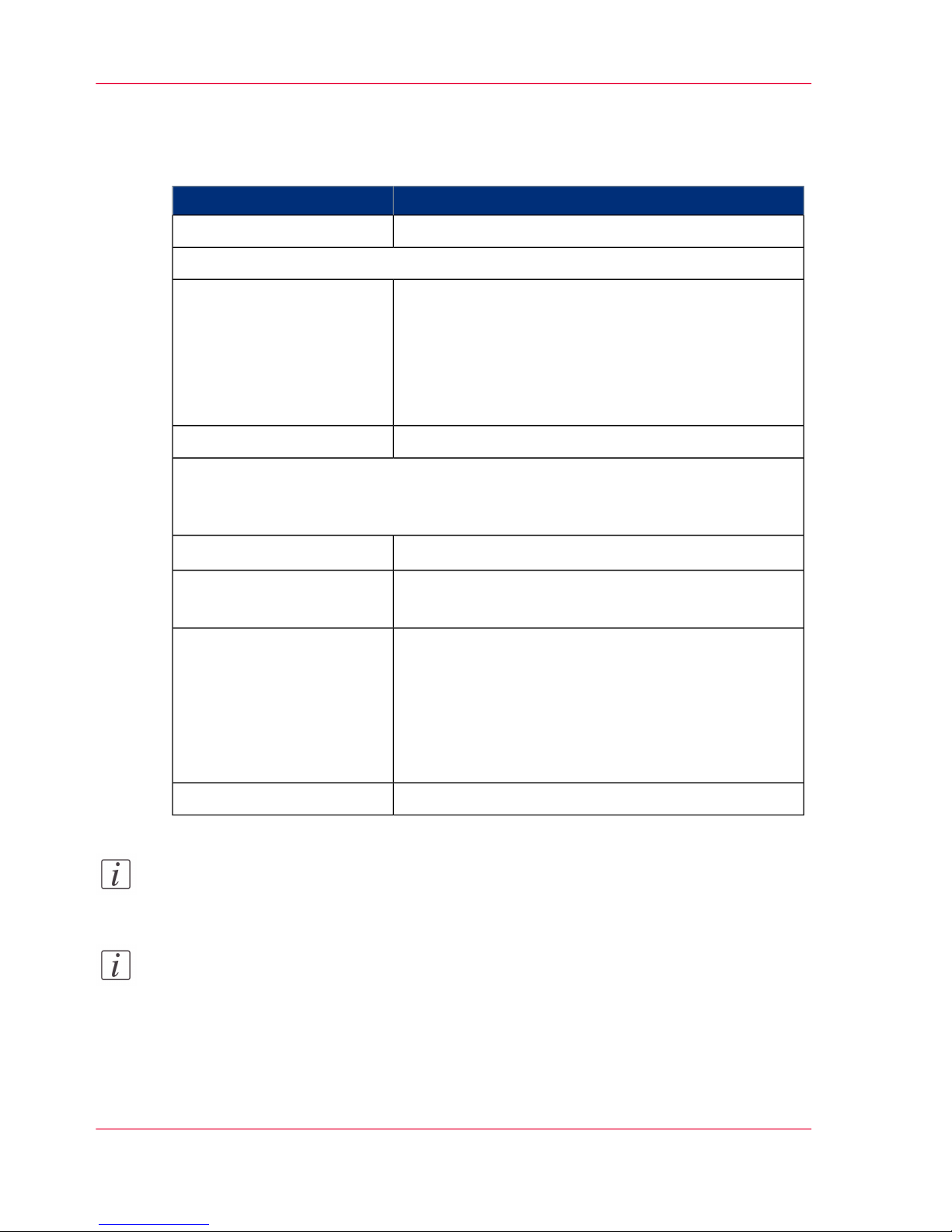
Main steps in calibration
#
Sub-stepMain step
‘2.0 Check the print quality’ on page 101. Check the print quality
Continue only if the colour reference chart does not meet your requirements.
‘3.1 Calibrate the EFI controller’ on page 12
or
‘3.1 Calibrate the Creo controller’ on page 17
or
‘3.1 Calibrate the Océ PRISMAsync controller’ on page
20
2. Calibrate the controller
‘3.2 Check the print quality’ on page 28
The result of the controller calibration as checked in 3.2 normally meets the required
print quality. If the print quality still does not meet your requirements, you can
consider to proceed with the printer calibration.
‘4.1 Perform the adjustment operation’ on page 30
1
3. Calibrate the printer
‘4.2 Adjust the white point (gamma offset)’ on page 33
1
‘4.3 Calibrate the EFI controller’ on page 39
2
or
‘4.3 Calibrate the Creo controller’ on page 44
2
or
‘4.3 Calibrate the Océ PRISMAsync controller’ on page
47
2
‘4.4 Check the print quality’ on page 55
Note:
1
Calibration of your copy process only requires step 4.1 and 4.2.
Note:
2
Calibration of the printer requires calibration of the controller because the controller
takes the printer settings into account at controller calibration.
Chapter 1 - Introduction8
Main steps in calibration
Page 9

Chapter 2
Check the print quality
o
Page 10

2.0 Check the print quality
Introduction
You can print the Océ Color Reference chart to check the print quality. You can download
the print files used in this document form the Océ website. Before you print this chart,
you need to warm up the machine.
Before you begin
Load the A4/Letter portrait reference media with the correct paper settings.
Load the A3/Tabloid reference media with the correct paper settings.
Note:
Reference media is the media that you use mostly (bulk). The Océ reference media is
Océ Top Color 90 g/m2.
Warm up the printer
1.
Print the file 'Océ Startup Page.pdf'.
Result
The Océ CS550/CS6xx Pro is warmed up and ready to evaluate the print quality.
Print the Océ Color Reference chart
1.
Print the file 'Océ Color Reference Chart.pdf'.
Result
The result is a printed Océ Color Reference chart to evaluate the print quality.
Chapter 2 - Check the print quality10
2.0 Check the print quality
Page 11

Chapter 3
Controller calibration
o
Page 12
3.1 Calibrate the EFI controller
Introduction
The external controller is either an EFI (IC303/IC305/IC408), a Creo (IC304/IC304Plus)
or an Océ PRISMAsync controller. This procedure describes the calibration of the EFI
controller. In case of an IC408 controller you must use CWS on a remote PC. Before
you can calibrate the EFI controller you must print the calibration chart.
Print the calibration chart
1.
From 'Command Workstation', click 'Server' - 'Manage color...'.
2.
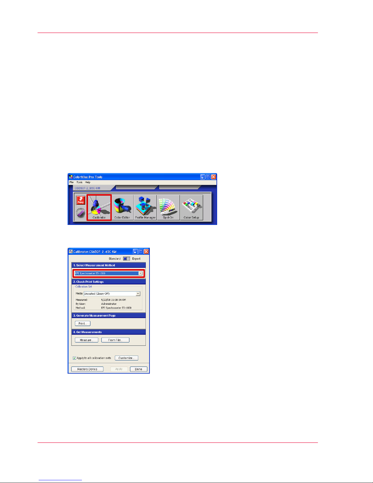
Click 'Calibrator'.
[1] Calibrator button
3.
Select or check the measurement method.
[2] Measurement method selection list
Chapter 3 - Controller calibration12
3.1 Calibrate the EFI controller
Page 13
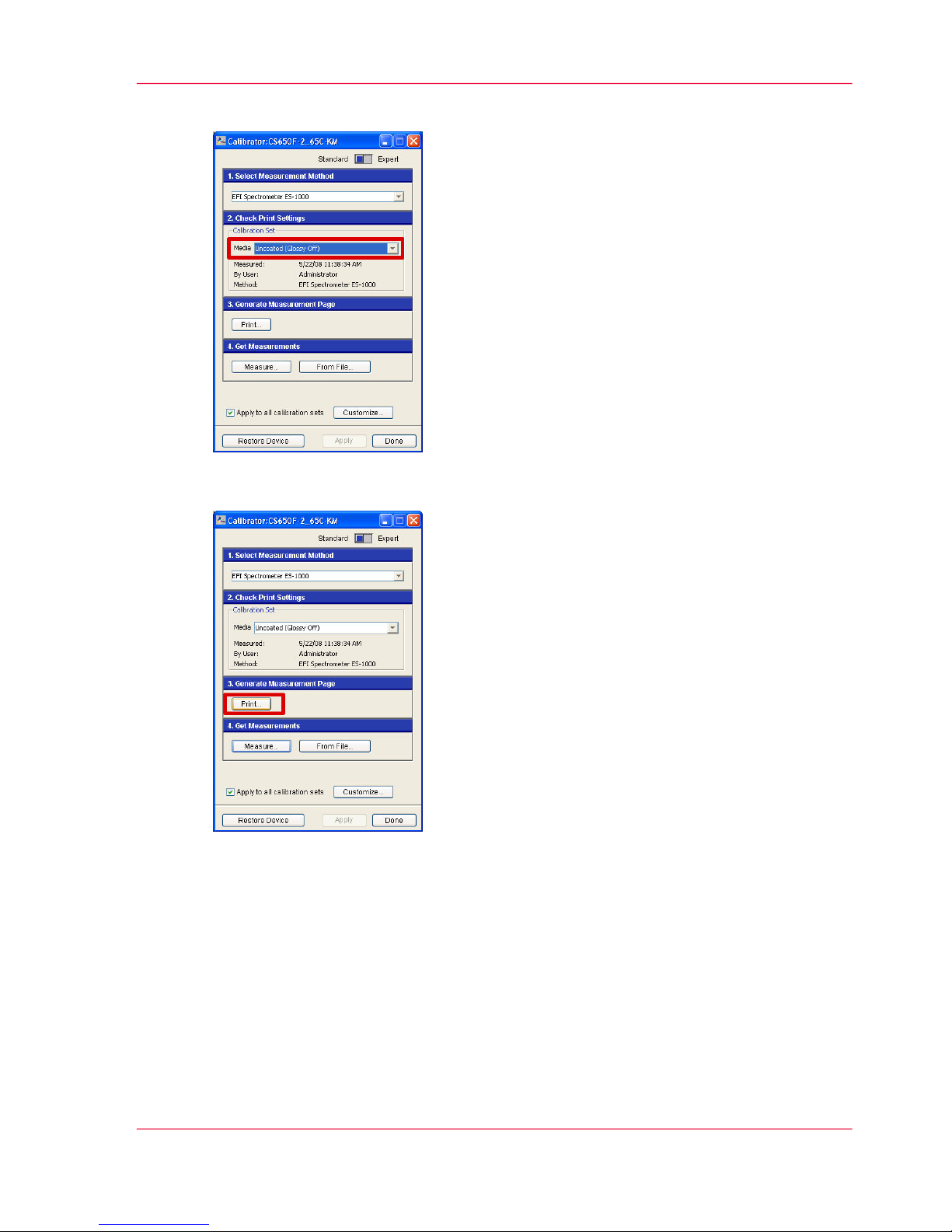
4.
Select the media you want to use for calibration.
[3] Media selection list
5.
Click 'Print...' to set the print options and print the sorted patches chart.
[4] Print options button
6.
Select the following settings.
■
At 'Page Type', select '34 Sorted patches' for A3/Tabloid (recommended).
Select '21 Sorted Patches' for A4/Letter.
■
At 'Paper Size', select the setting according to the previous step.
■
At 'Input tray', select the tray that contains the selected paper type and size.
■
At 'Number of copies', select 5.
Use the last print to calibrate.
■
At 'Show Advanced Options', check at 'Halftone' the correct screening. The default
is 'Dot1'.
Chapter 3 - Controller calibration 13
3.1 Calibrate the EFI controller
Page 14
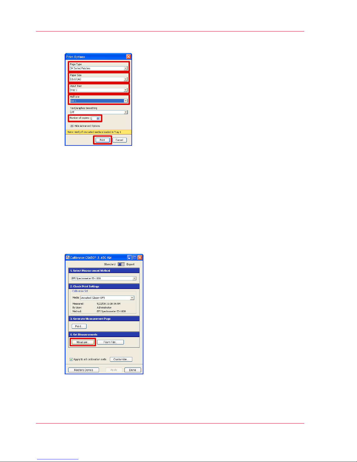
■
Click 'Print' to print the sorted patches chart.
[5] Print options lists and print button
7.
Click 'OK' to close the information window.
Result
The printer performs an automatic calibration adjustment and prints the sorted patches
chart.
Calibrate the EFI controller
1.
Click 'Measure...' to start the calibration.
[6] Measurement options button
Chapter 3 - Controller calibration14
3.1 Calibrate the EFI controller
Page 15
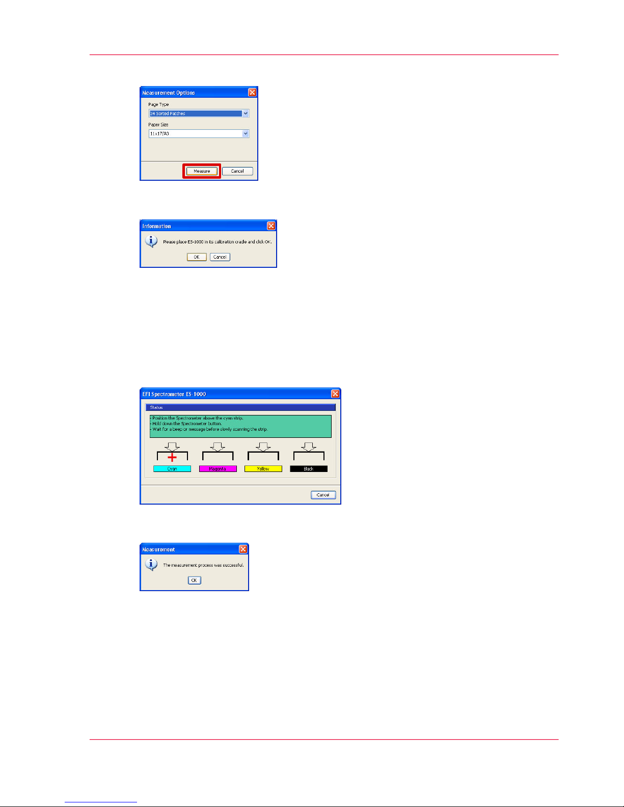
2.
Check the measurement options and click 'Measure'.
[7] Measurement button
3.
Check the spectrometer and click 'OK'.
[8] Spectrometer ready?
4.
Follow the instructions in the EFI Spectrometer window precisely.
Perform the following actions per colour.
■
Position the spectrometer at the blinking red cross above the column with coloured
patches.
■
Hold down the spectrometer button and wait for the beep.
■
Scan the column with patches slowly.
[9] Measurement instructions
5.
Click 'OK'.
[10] Measurement successful?
6.
Apply the calibration.
■
Check 'Apply to all calibration sets' to use this calibration for all media.
Chapter 3 - Controller calibration 15
3.1 Calibrate the EFI controller
Page 16
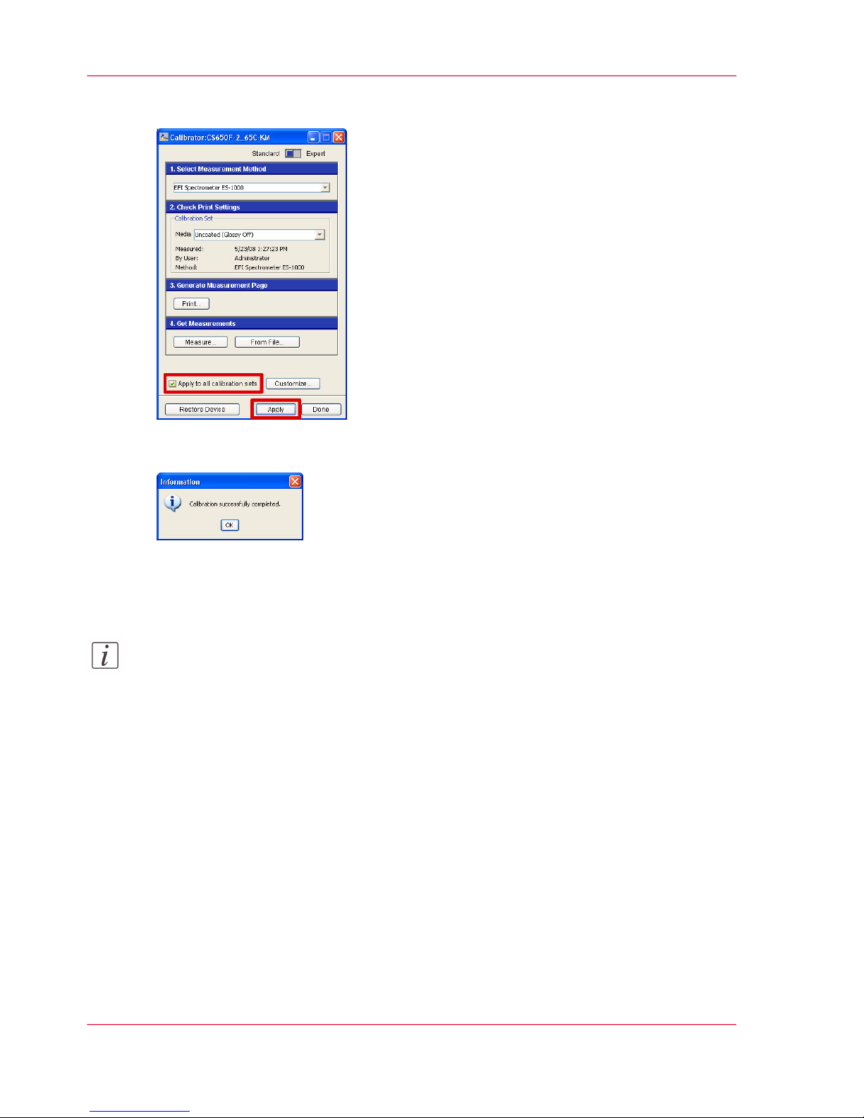
■
Click 'Apply'.
[11] Apply the measurement for all media?
7.
Click 'OK'.
[12] Calibration successful?
8.
To calibrate per media, return to step 3 of the 'Print the patches chart' .
Note:
Follow both the above procedures per screen you use.
Result
The EFI controller is calibrated.
Chapter 3 - Controller calibration16
3.1 Calibrate the EFI controller
Page 17

3.1 Calibrate the Creo controller
Introduction
The external controller is either an EFI (IC303/IC305/IC408), a Creo (IC304/IC304Plus)
or an Océ PRISMAsync controller. This procedure describes the calibration of the Creo
controller. At the beginning of the procedure you print a calibration chart that is used to
calibrate the Creo controller.
Calibrate the Creo controller
1.
Click 'Tools' - 'Calibration'.
The 'Color Calibration' window opens.
2.
Print the calibration chart.
■
At 'Tray', select the location of the media you use mostly.
■
At 'Media Type:', define the media you use mostly.
■
At 'Screening:', define the screening you use.
The default is 'Dot1'
■
At 'Number of copies:', select 5.
Use the last print to calibrate.
■
Click 'Print'
The printer performs an automatic calibration adjustment and makes the prints.
[13] Calibration chart settings
Chapter 3 - Controller calibration 17
3.1 Calibrate the Creo controller
Page 18

3.
Follow the instructions in the 'Color Calibration' window to perform the measurement.
[14] Measurement instructions
4.
Click 'Next' after successful calibration.
[15] Calibration successful?
Chapter 3 - Controller calibration18
3.1 Calibrate the Creo controller
Page 19

5.
Select the media for this calibration.
[16] Media selection window
6.
Click 'Finish'.
7.
Return to step 2 to calibrate other media you use.
Note:
Follow the above procedure per screen you use.
Result
The Creo controller is calibrated.
Chapter 3 - Controller calibration 19
3.1 Calibrate the Creo controller
Page 20

3.1 Calibrate the Océ PRISMAsync controller
Introduction
The external controller is either an EFI (IC303/IC305/IC408), a Creo (IC304/IC304Plus)
or an Océ PRISMAsync controller. This procedure describes the calibration of the Océ
PRISMAsync controller. At the beginning of the procedure you print a calibration chart
that is used to calibrate the Océ PRISMAsync controller.
Print a calibration chart
1.
From the 'System' view, press 'Calibrate'.
[17] 'System' view
The list of media families appears.
2.
Select the 'Media family' you want to calibrate and press 'OK'.
Chapter 3 - Controller calibration20
3.1 Calibrate the Océ PRISMAsync controller
Page 21

You can not select a media family that has no media defined.
[18] Media families
The list of halftones for the selected media family appears.
3.
Press the required halftone and press 'OK'.
[19] Halftones
The list of media for the selected media family appears.
Chapter 3 - Controller calibration 21
3.1 Calibrate the Océ PRISMAsync controller
Page 22

4.
Select the media you want to calibrate and press 'OK'.
[20] Media
The calibration view appears
5.
Press 'Print calibration chart'.
[21] Calibration view
The printer is now adjusting.
6.
Please wait and check the progress at the upper left corner of the operator panel.
Chapter 3 - Controller calibration22
3.1 Calibrate the Océ PRISMAsync controller
Page 23

Result
The printer prints a calibration chart for the selected media family, halftone and media.
Calibrate the Océ PRISMAsync controller
1.
Press 'Calibrate meter' and follow the instructions.
[22] 'Calibrate meter' option
Chapter 3 - Controller calibration 23
3.1 Calibrate the Océ PRISMAsync controller
Page 24

2.
Calibrate the meter.
[23] 'Place meter & push button'
■
Place the X-Rite i1 meter in the holder.
■
Press the button of the meter.
■
Please wait until the meter is calibrated.
3.
Put 4 sheets of the same media as the calibration chart under the calibration chart.
Chapter 3 - Controller calibration24
3.1 Calibrate the Océ PRISMAsync controller
Page 25

4.
Scan the rows of the coloured patches.
[24] 'Place meter & hold button'
■
Put the meter in the square at the left side of the first row.
■
Press and hold the button of the meter until you hear a beep.
■
Move the meter across the row of patches.
■
Release the button of the meter.
■
If the scan failed, select the current colour again on the operator panel and repeat the
scan.
■
If the can passed, repeat the previous actions for all other colours.
Chapter 3 - Controller calibration 25
3.1 Calibrate the Océ PRISMAsync controller
Page 26

5.
Press 'OK' to close the calibration view.
[25] Calibration view with succeeded scans
6.
Press 'Yes' to save and apply the calibration
[26] Calibration confirmation window
Chapter 3 - Controller calibration26
3.1 Calibrate the Océ PRISMAsync controller
Page 27

7.
Select one of the following options.
[27] Continue window
■
Press 'Yes' to continue with the calibration procedure for another media family.
■
Press 'No' to stop the calibration procedure.
Result
The controller is calibrated for the selected media family, halftone and media. Repeat the
calibration for every media family, halftone and media you use.
Chapter 3 - Controller calibration 27
3.1 Calibrate the Océ PRISMAsync controller
Page 28

3.2 Check the print quality
Introduction
The controller is now calibrated. You can print the Océ Colour Reference chart to check
the print quality.
Print the Océ Color Reference chart
1.
Print the file 'Océ Color Reference Chart.pdf'.
Result
The result of the controller calibration as checked normally meets the required print
quality. If the print quality still does not meet your requirements, you can consider to
proceed with the printer calibration. The printer calibration can give a better result when
the print quality of light colours and gradients is critical.
Chapter 3 - Controller calibration28
3.2 Check the print quality
Page 29

Chapter 4
Printer calibration
o
Page 30

4.1 Perform the adjustment operation
Note:
Only perform the printer calibration if the result after controller calibration does not
meet your requirements. In most cases the controller calibration will give the required
result.
Perform the adjustment operation
1.
Select the following buttons to open the 'Expert Adjustment Menu'.
Utility / counter (key).
■
■
'03 Machine Admin.Setting'
■
'01 System Setting'
■
'05 Expert Adjustment'
2.
Select '08 Execute Adjust Operation'.
[28] Expert Adjustment Menu
3.
Select the following buttons to define the adjustment items.
■
'Automatic Gamma Adj'
■
'Color Registration Adj.'
Chapter 4 - Printer calibration30
4.1 Perform the adjustment operation
Page 31

■
'OK'
[29] Select Adjustment item
4.
Select 'Exit' to start the automatic adjustment.
[30] Expert Adjustment Menu
The 'Machine' screen opens and displays 'Now adjusting'.
Chapter 4 - Printer calibration 31
4.1 Perform the adjustment operation
Page 32

Result
The automatic adjustment takes approximately 4 minutes. The machine displays 'Ready
to print' when the adjustment is completed.
Chapter 4 - Printer calibration32
4.1 Perform the adjustment operation
Page 33

4.2 Adjust the white point (gamma offset)
Print the gamma calibration chart
1.
Select the following buttons to open the 'Expert Adjustment Menu'.
Utility / counter (key).
■
■
'03 Machine Admin.Setting'
■
'01 System Setting'
■
'05 Expert Adjustment'
2.
Select '07 Quality Adjustment'.
[31] Expert Adjustment Menu
Chapter 4 - Printer calibration 33
4.2 Adjust the white point (gamma offset)
Page 34

3.
Select '02 Printer Gamma Offset Auto Adj.'.
[32] Quality Adjustment Menu
4.
Select the following buttons to print the gamma calibration chart.
■
'Next' and 'Previous' to define the required screening. The default is 'Dot1'
■
'Adj. data reset' to set the gamma offset values to zero.
■
'Readjust' to re-adjust the gamma offset.
Chapter 4 - Printer calibration34
4.2 Adjust the white point (gamma offset)
Page 35

■
'Copy' to open the 'Machine' screen.
[33] Printer gamma offset automatic adjustment menu
5.
Make sure the correct reference paper is selected (A4/Letter, portrait) and press the green
'Start' key.
Result
A printed test chart to set the gamma offset values automatically.
Set the gamma offset values automatically
1.
Place the printed test chart on the scanner, face down with the green arrow to the left.
2.
Place a stack of 10 white pages on top of the test chart.
Chapter 4 - Printer calibration 35
4.2 Adjust the white point (gamma offset)
Page 36

3.
Press 'Start'.
[34] Printer gamma offset automatic adj. menu
The values for the gamma offset are calculated automatically. New values are used to
print a new test chart.
4.
Check the calibration status message at the upper left.
If the message is 'Touch [COPY] to output a chart', do the following.
■
Select 'Copy'.
■
Press the green 'Start' key.
■
Repeat step 1-4.
Chapter 4 - Printer calibration36
4.2 Adjust the white point (gamma offset)
Page 37

Note:
Make sure you repeat step 1-4 until the message is 'Completed normally'.
[35] Calibration status message
If the message is 'Completed normally', the printer is adjusted properly.
[36] Calibration status message
Chapter 4 - Printer calibration 37
4.2 Adjust the white point (gamma offset)
Page 38

Result
Now the white point of the printer is adjusted.
Chapter 4 - Printer calibration38
4.2 Adjust the white point (gamma offset)
Page 39

4.3 Calibrate the EFI controller
Introduction
The external controller is either an EFI (IC303/IC305/IC408), a Creo (IC304/IC304Plus)
or an Océ PRISMAsync controller. This procedure describes the calibration of the EFI
controller. In case of an IC408 controller you must use CWS on a remote PC. Before
you can calibrate the EFI controller you must print the calibration chart.
Print the calibration chart
1.
From 'Command Workstation', click 'Server' - 'Manage color...'.
2.
Click 'Calibrator'.
[37] Calibrator button
3.
Select or check the measurement method.
[38] Measurement method selection list
Chapter 4 - Printer calibration 39
4.3 Calibrate the EFI controller
Page 40

4.
Select the media you want to use for calibration.
[39] Media selection list
5.
Click 'Print...' to set the print options and print the sorted patches chart.
[40] Print options button
6.
Select the following settings.
■
At 'Page Type', select '34 Sorted patches' for A3/Tabloid (recommended).
Select '21 Sorted Patches' for A4/Letter.
■
At 'Paper Size', select the setting according to the previous step.
■
At 'Input tray', select the tray that contains the selected paper type and size.
■
At 'Number of copies', select 5.
Use the last print to calibrate.
■
At 'Show Advanced Options', check at 'Halftone' the correct screening. The default
is 'Dot1'.
Chapter 4 - Printer calibration40
4.3 Calibrate the EFI controller
Page 41

■
Click 'Print' to print the sorted patches chart.
[41] Print options lists and print button
7.
Click 'OK' to close the information window.
Result
The printer performs an automatic calibration adjustment and prints the sorted patches
chart.
Calibrate the EFI controller
1.
Click 'Measure...' to start the calibration.
[42] Measurement options button
Chapter 4 - Printer calibration 41
4.3 Calibrate the EFI controller
Page 42

2.
Check the measurement options and click 'Measure'.
[43] Measurement button
3.
Check the spectrometer and click 'OK'.
[44] Spectrometer ready?
4.
Follow the instructions in the EFI Spectrometer window precisely.
Perform the following actions per colour.
■
Position the spectrometer at the blinking red cross above the column with coloured
patches.
■
Hold down the spectrometer button and wait for the beep.
■
Scan the column with patches slowly.
[45] Measurement instructions
5.
Click 'OK'.
[46] Measurement successful?
6.
Apply the calibration.
■
Check 'Apply to all calibration sets' to use this calibration for all media.
Chapter 4 - Printer calibration42
4.3 Calibrate the EFI controller
Page 43

■
Click 'Apply'.
[47] Apply the measurement for all media?
7.
Click 'OK'.
[48] Calibration successful?
8.
To calibrate per media, return to step 3 of the 'Print the patches chart' .
Note:
Follow both the above procedures per screen you use.
Result
The EFI controller is calibrated.
Chapter 4 - Printer calibration 43
4.3 Calibrate the EFI controller
Page 44

4.3 Calibrate the Creo controller
Introduction
The external controller is either an EFI (IC303/IC305/IC408), a Creo (IC304/IC304Plus)
or an Océ PRISMAsync controller. This procedure describes the calibration of the Creo
controller. At the beginning of the procedure you print a calibration chart that is used to
calibrate the Creo controller.
Calibrate the Creo controller
1.
Click 'Tools' - 'Calibration'.
The 'Color Calibration' window opens.
2.
Print the calibration chart.
■
At 'Tray', select the location of the media you use mostly.
■
At 'Media Type:', define the media you use mostly.
■
At 'Screening:', define the screening you use.
The default is 'Dot1'
■
At 'Number of copies:', select 5.
Use the last print to calibrate.
■
Click 'Print'
The printer performs an automatic calibration adjustment and makes the prints.
[49] Calibration chart settings
Chapter 4 - Printer calibration44
4.3 Calibrate the Creo controller
Page 45

3.
Follow the instructions in the 'Color Calibration' window to perform the measurement.
[50] Measurement instructions
4.
Click 'Next' after successful calibration.
[51] Calibration successful?
Chapter 4 - Printer calibration 45
4.3 Calibrate the Creo controller
Page 46

5.
Select the media for this calibration.
[52] Media selection window
6.
Click 'Finish'.
7.
Return to step 2 to calibrate other media you use.
Note:
Follow the above procedure per screen you use.
Result
The Creo controller is calibrated.
Chapter 4 - Printer calibration46
4.3 Calibrate the Creo controller
Page 47

4.3 Calibrate the Océ PRISMAsync controller
Introduction
The external controller is either an EFI (IC303/IC305/IC408), a Creo (IC304/IC304Plus)
or an Océ PRISMAsync controller. This procedure describes the calibration of the Océ
PRISMAsync controller. At the beginning of the procedure you print a calibration chart
that is used to calibrate the Océ PRISMAsync controller.
Print a calibration chart
1.
From the 'System' view, press 'Calibrate'.
[53] 'System' view
The list of media families appears.
2.
Select the 'Media family' you want to calibrate and press 'OK'.
Chapter 4 - Printer calibration 47
4.3 Calibrate the Océ PRISMAsync controller
Page 48

You can not select a media family that has no media defined.
[54] Media families
The list of halftones for the selected media family appears.
3.
Press the required halftone and press 'OK'.
[55] Halftones
The list of media for the selected media family appears.
Chapter 4 - Printer calibration48
4.3 Calibrate the Océ PRISMAsync controller
Page 49

4.
Select the media you want to calibrate and press 'OK'.
[56] Media
The calibration view appears
5.
Press 'Print calibration chart'.
[57] Calibration view
The printer is now adjusting.
6.
Please wait and check the progress at the upper left corner of the operator panel.
Chapter 4 - Printer calibration 49
4.3 Calibrate the Océ PRISMAsync controller
Page 50

Result
The printer prints a calibration chart for the selected media family, halftone and media.
Calibrate the Océ PRISMAsync controller
1.
Press 'Calibrate meter' and follow the instructions.
[58] 'Calibrate meter' option
Chapter 4 - Printer calibration50
4.3 Calibrate the Océ PRISMAsync controller
Page 51

2.
Calibrate the meter.
[59] 'Place meter & push button'
■
Place the X-Rite i1 meter in the holder.
■
Press the button of the meter.
■
Please wait until the meter is calibrated.
3.
Put 4 sheets of the same media as the calibration chart under the calibration chart.
Chapter 4 - Printer calibration 51
4.3 Calibrate the Océ PRISMAsync controller
Page 52

4.
Scan the rows of the coloured patches.
[60] 'Place meter & hold button'
■
Put the meter in the square at the left side of the first row.
■
Press and hold the button of the meter until you hear a beep.
■
Move the meter across the row of patches.
■
Release the button of the meter.
■
If the scan failed, select the current colour again on the operator panel and repeat the
scan.
■
If the can passed, repeat the previous actions for all other colours.
Chapter 4 - Printer calibration52
4.3 Calibrate the Océ PRISMAsync controller
Page 53

5.
Press 'OK' to close the calibration view.
[61] Calibration view with succeeded scans
6.
Press 'Yes' to save and apply the calibration
[62] Calibration confirmation window
Chapter 4 - Printer calibration 53
4.3 Calibrate the Océ PRISMAsync controller
Page 54

7.
Select one of the following options.
[63] Continue window
■
Press 'Yes' to continue with the calibration procedure for another media family.
■
Press 'No' to stop the calibration procedure.
Result
The controller is calibrated for the selected media family, halftone and media. Repeat the
calibration for every media family, halftone and media you use.
Chapter 4 - Printer calibration54
4.3 Calibrate the Océ PRISMAsync controller
Page 55

4.4 Check the print quality
Introduction
The printer is now calibrated. You can print the Océ Colour Reference chart to check
the print quality.
Print the Océ Color Reference chart
1.
Print the file 'Océ Color Reference Chart.pdf'.
Result
A printed Océ color reference chart to evaluate the print quality.
Chapter 4 - Printer calibration 55
4.4 Check the print quality
Page 56

Index
Calibration
Creo controller .........................................17, 44
EFI controller ..........................................12, 39
main steps .........................................................8
Océ PRISMAsync controller ....................20, 47
why ...................................................................7
Color reference chart
Color reference chart ......................................10
Configuration
Configuration ...................................................6
G
Gamma offset
Gamma offset .................................................33
P
Print quality
Print quality ...................................................10
after controller calibration ...............................28
after printer calibration ...................................55
at start ............................................................10
W
Warm up
Warm up ........................................................10
White point
White point ....................................................33
56
Index
 Loading...