

Page 1
Océ CS6407
Read this User’s Guide (including Safety Information)
carefully before use of this printer and handle it properly.
After reading, keep it for later use.
Basic Operation Guide
1
Documentnumber
Wide Format Solvent Inkjet Printer
Océ CS6407
Océ Technologies B.V.
Introduction For your basic operation Maintenance When encountering a problem Appendix
Page 2

Océ CS6407 Wide Format Solvent Inkjet Printer Basic Operation Guide
Edition 1, April 2010
Copyright
© 2010, Océ-Technologies B.V. Venlo, The Netherlands.
All rights reserved. No part of this work may be reproduced, copied, adapted, or transmitted in any form or by any
means without written permission from 'companyname'.
Océ-Technologies B.V. makes no representation or warranties with respect to the contents hereof and speci cally
disclaims any implied warranties of merchantability or tness for any particular purpose.
Further, Océ-Technologies B.V. reserves the right to revise this publication and to make changes from time to
time in the content hereof without obligation to notify any person of such revision or changes.
Trademarks
Océ®, Océ CS6407® are registered trademarks of Océ-Technologies B.V.
Microsoft® and Windows® are either registered trademarks or trademarks of Microsoft® Corporation in the United
States and / or other countries.
Products in this publication are referred to by their general trade names. In most, if not all cases, these
designations are claimed as trademarks or registered trademarks of their respective companies.
Note:
Visit Océ on the internet at www.oce.com for the latest information.
Page 3

3
Introduction
Océ 6407 Wide Format Solvent Inkjet Printer (hereafter simply called the Printer.) is equipped with built-in USB
interface that adopts solvent ink and supports media of up to 74-inch width.
The Océ 6407 Wide Format Solvent Inkjet Printer Basic Operation Guide describes:
- The Printer’s features and main components
- Information required for the operation
- Basic operations to turn the Printer on and o and to handle the media and ink system
To operate the Printer safely and properly, before starting the operation be sure to read the following.
- Safety precautions
- Delivery products
- Manual legend (notation rules)
Keep this guide near the Printer so that you can quickly access it at any time.
Page 4
Océ 6407 Basic Operation Guide
4
To perform your rst printing
Basic Operation Guide
Read the Basic Operation Guide before your rst Printer operation.
This guide describes the basic handling and daily operation of
media, printing, and maintenance.
To print on other media
To perform double-sided printing
To perform the Printer’s maintenance
To replace the Printer’s ink pack
To replace the Printer’s waste ink bottle
To recover error messages
To clear media jams
How do the two Guides work?
Océ CS6407
Read this User’s Guide carefully before use of this printer and
handle it properly.
After reading, keep it for later use.
Basic Operation Guide
1
Documentnumber
Wide Format Solvent Inkjet Printer
Océ 6407
Océ Technologies B.V.
P.29
P.50
P.54
P.58
P.86
P.84
P.76
P.75
Page 5
5
Advanced Operation Guide
Read the Advanced Operation Guide so that you can operate
the Printer eectively.
This Guide describes the Printer’s ne setting and adjustment to
maximize the Printer’s performance.
To clear banding, white lines, and bleeding
To operate the Printer with ne settings
To print on cut-sheet media
To change heater temperature while printing
To turn the Printer o
To create a new media preset
To switch between 4-color and 8-color modes
Océ CS6407
Read this User’s Guide carefully before use of this printer and
handle it properly.
After reading, keep it for later use.
Wide Format Solvent Inkjet Printer
Advanced Operation Guide
Océ 6407
Océ Technologies B.V.
P.66
P.26
P.42
P.52
P.8
P.36
P.60
Page 6

Océ 6407 Basic Operation Guide
6
TABLE OF CONTENTS
Introduction
3
Safety precautions
7
General warning and cautions
8
Regulation Notices (country dependent)
10
Handling precautions
12
Components delivered with this product
15
Manual legend (Notational rules)
16
Operating conditions
19
Introduction
20
Appearance / Main components and their
functions
20
Printer rear (supply side)
20
Printer interior
21
Operation panel
22
Printer heater unit
23
Online and o ine
24
Online
24
Offline
24
Supported media
25
Vinyl
25
Banner
25
Mesh banner
25
Backlit banner (FF)
25
Solvent printing coated paper
25
For your basic operation
26
Precautions to prevent media jams
27
Basic operation for printing
29
Printing workflow overview
29
Procedure to remove media roll from the Printer
43
Media at take-up side
43
Media at supply side
46
Procedure to remove scroller flange from media roll
48
To print on other media
50
To print on Vinyl, Mesh banner, Backlit banner (FF), or
Solvent printing coated paper
50
To take up media in LOOSE winding mode
52
To perform double-sided printing
54
Maintenance
58
Daily maintenance
58
Check the wiper blade for contamination and replenish
wiper cleaning liquid
60
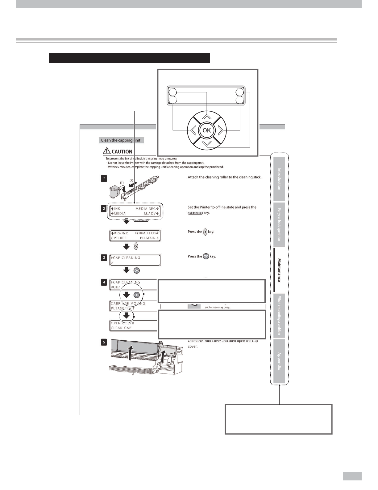
Clean the capping unit
61
Replenish spittoon absorber liquid
63
Check the waste ink bottle
64
Clean the carriage
64
Cleaning the madia edge guard
67
Performing normal cleaning
68
Print the nozzle print pattern
68
Cleaning
70
Clean the exterior
70
Clean the front cover and front paper guide
70
Carriage cleaning
70
After today’s operation
71
When encountering a problem
72
Check your problem
72
How to clear media jams
75
When an error message is displayed
76
Out of ink while printing
80
The media was skewed.
81
Warning messages
82
Move the Printer
83
Replace a waste ink bottle
84
Install and replace an ink pack
86
Replace a spittoon case
88
Replace a wiper blade
90
Appendix
92
Basic speci cations
92
Consumables
93
Addresses of lacal Océ organisations
95
Index
98
Page 7

7
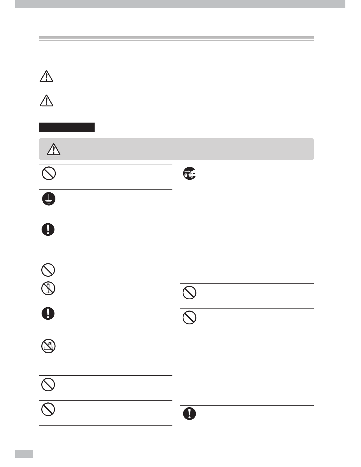
The following symbols are used in the Guides to ensure the Printer’s proper operation and to prevent the Printer
from being damaged. Follow the instructions marked with these symbols:
This symbol ( ) denotes items that require special care while
executing a certain procedure or operation.
This symbol ( ) denotes items that are forbidden.
This symbol ( ) denotes items you should follow to prevent
accidents or injury.
Example of symbols :
WARNING
CAUTION
Failuretofollowtheguidelinesmarkedwiththis
symbolcouldresultinseriouspersonalinjuryor
death.
Failuretofollowtheguidelinesmarkedwiththis
symbolcouldresultinminorpersonalinjuryor
damagetotheproduct.
Safety precautions
Page 8
Océ 6407 Basic Operation Guide
8
Be sure to read warnings below before use.
WARNING
Use the power supply voltage speci ed on the
nameplate. Avoid overloading the printer’s
electrical outlet with multiple devices.
Be sure the printer is well grounded. Failure
to ground the printer may result in electrical
shock, re, and susceptibility to electromagnetic
interference.
Always hold the power cord by the plug when
connecting and disconnecting from the power
outlet.
Never pull on the cord because this may damage
it and create risk of re and electric shock.
Do not use a conversion plug.
Do not disassemble or repair the Printer by
yourself. Do not reinstall the printer in a new
location. Call your service representative.
DO NOT damage, break, process, or heat the
power cable. If it is damaged, replace it with a
new one. Using a damaged power cable may
cause re or electric shock.
NEVER use the Printer in a place of extreme
humidity or any place where it can possibly be
splashed by any liquids. If any liquid gets into the
Printer, it could lead to re, electric shock, or a
breakdown.
Do not allow metal or liquids to touch the
internal parts of the Printer. Doing so may cause
re, electric shock, or other serious hazards.
DO NOT disconnect or connect the power cord
with wet hands. Doing so may lead to electric
shock.
Power OFF the printer, unplug the power cord
from the power outlet, and contact your service
representative in any of the following cases.
Using the printer continuously in an abnormal
state may result in an accident or re.
- Smoke, strange noise or smell is generated
from the Printer or the Printer is overheated.
- There is smoke or an unusual smell coming
from the printer.
- The Printer is making an unusual noise during
normal operation.
- A piece of metal or a liquid (not part of
cleaning and maintenance routines) touches
internal parts of the Printer.
- An error requiring service by a service
representative occurs.
Ink used in the ink packs and subcartridges is
combustible. Do not use or store near open
ames, sparks, or other sources of ignition.
Avoid contact between skin, eyes, and clothing
and the Printer’s following consumables: ink,
storage liquid, cleaning liquid, cap cleaning
liquid, wiper cleaning liquid, and waste ink.
- Immediately wash skin with soapy water.
- Use an approved eye wash station if ink is
splashed into eyes and consult a doctor if
necessary. If an approved eye wash station is
unavailable, flush eyes with cold water and
consult a doctor Remove clothing soaked with
ink from contact with skin.
Do not swallow ink. If swallowed, do not induce
vomiting and seek immediate medical attention.
DO NOT place the printer on an unstable table or
at a slant place. If it falls, it maylead to injury.
General warning and cautions
The following symbols are used in the Operation Guides to ensure the proper use of the Printer and to prevent
the Printer from being damaged. Follow the instructions marked with these symbols.
WARNING
Failure to follow the guidelines marked with this symbol could result in serious personal
injury or death.
CAUTION
Failure to follow the guidelines marked with this symbol could result in minor personal
injury or damage to the product.
General warnings
Page 9

9
To ensure safe operation of the Printer, pay attention to all the warnings and cautions contained
throughout this manual.
Do not touch heater surfaces in the media path.
This may cause burns.
Keep ink packs, subcartridges, and waste ink
bottles out of the reach of children.
General cautions
CAUTION
Ensure to read cautions below before use.
Operate the Printer carefully near the Printer's
movable parts, so that your hands or your
clothes are not caught in the Printer.
Install and operate the printer in a wellventilated area. Otherwise the operator may
feel sickish. In such a case, take a rest in a wellventilated place.
Handle media rolls with care. They can be
heavy and di cult to move in con ned spaces.
In some cases, two people should move and
install media rolls. Dropping a media roll could
cause personal injury or damage to the printer.
Carrying with dolly is recommended.
Page 10

Océ 6407 Basic Operation Guide
10
Regulation Notices (country dependent)
Radio Interference suppression (all countries except USA)
Warning: This is a Class A product. In a domestic environment this product may cause radio
interference in which case the user may be required to take adequate measures.
FCC approval (USA- only)
Note: This system has been tested and found to comply with the limits for a class A digital
device, pursuant to part 15 of the FCC Rules. These limits are designed to provide
reasonable protection against harmful interference when the system is operated in a
commercial environment. This system generates, uses, and can radiate radio frequency
energy and, if not installed and used in accordance with the instruction manual, may
cause harmful interference to radio communications. Operation of this equipment in
a residential area is likely to cause harmful interference in which case the user will be
required to correct the interference at his own expense.
ICES-003; Interference-causing equipment (Canada- only)
This Class A digital apparatus complies with Canadian ICES-003. Cet appareil
numérique de la classe A est conforme à la norme NMB-003 du Canada.
End of Life; WEEE (EU- only)
The symbol "the crossed-out wheeled bin" indicates that at end-of-life of the equipment
separate collection is required in the EU Member States. The black bar speci es that the
appliance is put on the market after 13 August 2005. Reference: Directive 2002/96/EC.
Contact your local Océ -organization for further information.
General information (All countries)
Caution labels and notations (All countries)
You can nd the power-marking label near the mains entrance. If connection to a
di erent mains voltage is required, contact Customer Service.
Do not remove caution labels or caution notations. If a label or notation is soiled,
please clean the label or notation. If you cannot make label or notation legible, or if the
label or notation is damaged, please contact your service representative.
Page 11

11
Space requirements and operation precautions (All countries)
The required operating space of this product will be communicated to each customer
by the local sales representative during the Site Survey.
Please refer to the corresponding Safety Data Sheets for speci c safety information,
including the dimensions of the product, the recommended room volume and
ventilation rate. You can download the Safety Data Sheets from the support site of
your product at http://global.oce.com/support/.
Operating environment (All countries)
The environmental requirements for correct operation of the machine are as follows:
Operating temperature (T): 15 °C (59 °F) to 30 °C (86 °F)
Relative Humidity (RH): 30 % to 70 %
Page 12
Océ 6407 Basic Operation Guide
12
Handling precautions
The precautions below are recommended to avoid damage to the Printer and its components.
Power supply
1. Install the Printer near the socket. To pull out the power plug in an emergency, the power socket must
be reached easily.
2. Do not share the power supply with the noise generating devices such as a motor.
3. Use the power supply voltage speci ed on the nameplate.
4. Monthly turn o the Printer and check the following:
- The power plug is inserted into the socket securely.
- No dust is accumulated between the plug terminals and socket. When dust is found, clean the area
with a dry cloth.
Printer
1. Do not place anything on the top of the printer. Do not rest your elbows on the Printer. Especially be
careful not to block the printer's exhaust outlet shown by the gure below.
2. Do not apply shock or stress to the Printer.
3. During the print operation, do not open the front cover, nor set the pressure control knob to “Open.”
Otherwise the printer operation is terminated.
4. Do not clean the cover’s surface with benzene or paint thinner. This may damage the Printer’s paint.
Clean the cover’s smear with a soft cloth. If the cover is considerably smeared, wipe it o with a cloth
moistened with water-diluted neutral detergent. If it is not cleaned, the smear may a ect the Printer’s
surface painting.
5. Always use the SIIT-speci ed attachments and options. The other products may degrade the image
quality, damage the Printer, and disable the maintenance.
6. Never touch the print head nozzles. They can be easily damaged or clogged.
Regular inspection and maintenance
Make sure you observe the appropriate maintenance guideline.
1. Clean the capping unit and wiper blade every day.
2. Everyday check visually the remaining wiper cleaning liquid is the speci ed quantity or more.
3. Clean the print head every two months with the head cleaning kit (IP7-125).
4. If you leave the Printer o for more than 2 weeks, perform the service cleaning.
5. If, after the service cleaning, you leave the Printer for a long time and again you start the print operation
with the Printer, be sure to perform the head wash and charge the ink system.
Consumables
1. SIIT ink packs should be installed before the “Install By” date printed on the pack. The other ink may
damage the Printer, and the Printer repair fee is borne by you.
2. To ensure the quality, validated date is printed on the SIIT ink pack, storage liquid, and cleaning liquid.
Use the consumables before they expire. The expired consumables may cause deterioration in print
quality or the Printer’s malfunction.
3. Put used ink packs into a plastic bag and dispose of them as industrial waste. Observe local regulations
Page 13

13
for disposal of consumables.
4. Unpack the SIIT ink pack package only when they are installed. Do not store SIIT ink packs in direct
sunlight. Store the SIIT ink packs in a cool, dry place. This prevents deterioration of the ink during
storage.
5. Do not disassemble the ink packs and subcartridges. They are intended for single use only.
6. Do not drop the ink packs and subcartridges. Avoid shock to them. The drop or shock may cause an ink
leakage.
Media
Supported media
The Printer supports the solvent inkjet media of the types below. Note that the print condition may change
depending on the environmental conditions and the media production batch. So you are recommended to test
the print with the media beforehand.
For details, contact your service representative.
z Vinyl
z Banner
z Mesh banner
z Backlit banner (FF)
z Solvent printing coated paper
Precautions on storing media
At storing media, packed or unpacked, avoid direct sunlight and water stained. To avoid dust put the
media into a box or a bag, and keep it in a cool and dark place.
Avoid a rapid temperature change to prevent a dew condensation.
Do not store media upright. The media stored upright may be deformed to be telescopic due to its
weight, or may deform its edge.
Do not pile up the roll media.
Precautions on disposing of media
Dispose of media or printout in compliance with all local, state, and federal regulations.
Precautions on using media
Do not subject the unpacked media to the temperature and humidity change. Before loading the
media on the Printer, leave the media in the operating environment for three hours or more. Note that
the ambient humidity change may a ect the media by turning on or o the air conditioner.
The media may be curled in a lower temperature, and wrinkled in a higher temperature. Keep the
temperature around 23°C and the humidity around 50% when you use the media.
Do not use a part of media when the part is scratched, wrinkled, turned, or with obstructions. Never use
the damaged media, as the right and left edges of the media are especially critical to feed media on the
Printer. Besides, do not drop the media and avoid water stained, which may degrade the image quality,
and cause the Printer’s malfunction.
Do not touch the printed image but the margin part. The image quality may be degraded by your
insensible sebum and sweat.
When the media is wound telescopically at loading on the Printer, correct the slippage before using.
Page 14
Océ 6407 Basic Operation Guide
14
Precautions on handling printouts
Do not touch the printed surface of the media before the ink dries, or especially 24 hours after printed.
Handle the printout by securing the margins.
Do not scratch the printout to avoid the color lost or transferred. To avoid the printout’s color
transferred, do not put the printed media on the other printed media with their printed surface facing
each other.
Do not put the printed media on the printout from copier or laser printer. The printouts’ ink or toner
may stick the two printouts.
Note that an ink on the printed surface may come o if the surface is rubbed hard or scratched.
The printed image may bleed or be lost if the water-stained printout is scratched hard or left.
Other precautions
Media loses its color and quality with age. Check the media condition and select the media with better
condition.
Cut the media carefully, as its paper dust may cause bubble surface at laminated.
When adhesive-backed media is applied, some adhesive agent may be left on the platen, which
may cause a media jam. So clean the agent completely with a soft cloth moistened with the neutral
detergent.
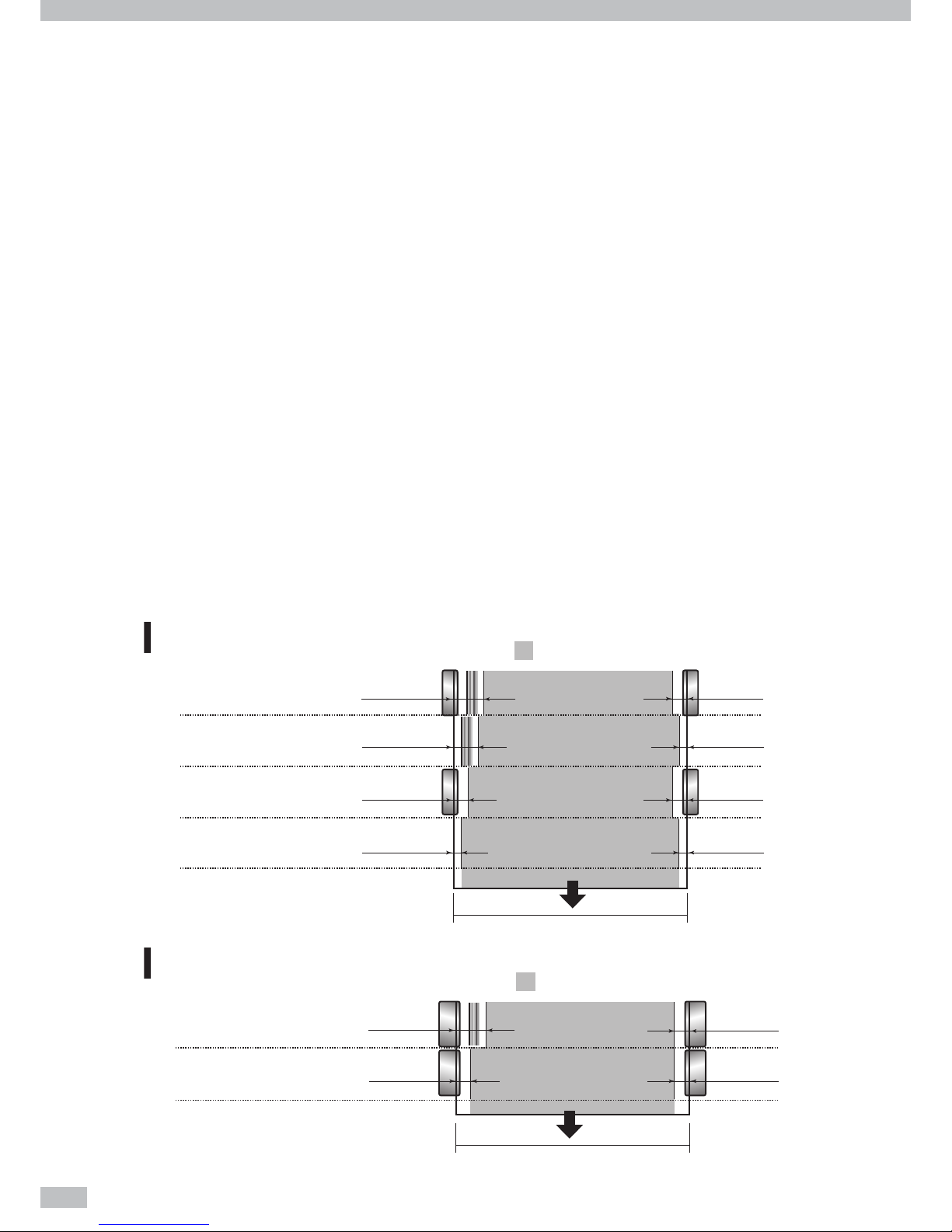
Available area on media
The available area on media in scanning direction depends on media width, media edge guards application,
and stripe bar presence. With the media edge guards and stripe bar applied, your available area is decreased by
34.9mm in right and 10.0mm in left. The available are is decreased more when the optional product below is
applied:
- Wide type media edge guards for platen sheet
Media width
Media width
Printable area
Color stripe :YES
Printable area
Media edge guards :YES
Color stripe :NO
Media edge guards :YES
41.9mm
15.0mm 15.0mm
15.0mm
Without wide type media edge guards for platen
sheet
ޓ
With wide type media edge guards
34.9mm
29.9mm
10.0mm 10.0mm
10.0mm
5.0mm 5.0mm
5.0mm
Color stripe :YES
Media edge guards :YES
Color stripe :YES
Media edge guards :NO
Color stripe :NO
Media edge guards :YES
Color stripe :NO
Media edge guards :NO
Page 15
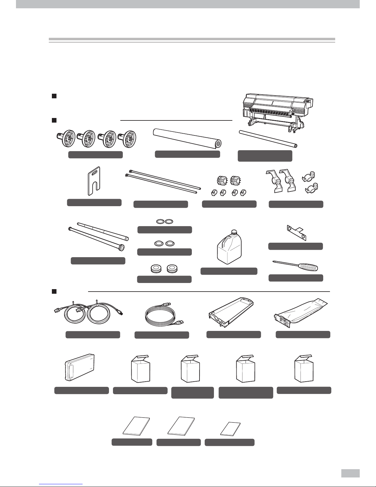
15
The following components are delivered with the Printer, and installed to the Printer at the Printer installation,
check that all the components below are delivered.
If any item is missing or damaged, contact Océ from whom you purchased the Printer or the nearest service
depot.
(Supply side) (Take up side)
Scloller flange
<4 pieces>
Flange spacer
<1 piece>
Flange holder
<1 piece>
Tension bar
(with ange: 1 piece)
(with no ange S: 2, ML: 1, L: 1)
<2 pieces>
Tension bar flange
<2 pieces>
Fixing ring
<2 pieces>
Tension bar flange with screw
<1 set>
Waste ink bottle IP6-109
<1 bottle>
Power cable
<2 pieces>
Subcartridge
<8 pieces>
Basic Operation Guide
(this guide)
<1 volume>
Advanced Operation Guide
<1 volume>
Quick reference guide
<1 volume>
Spittoon absorber
liquid
29953844
<1 set>
Spittoon absorber liquid(100 ml) : 3 bottles
Daily maintenance kit
29953842
<1 set>
• Cap cleaning liquid : 300 ml
• Wiper cleaning liquid : 200 ml
• Spittoon absorber liquid : 100 ml
• Cleaning roller : 30 pieces
• Cleaning swab : 10 pieces
• Dripper : 10 pieces
• Tweezers : 1 piece
• Cleaning stick : 1 piece
• Spittoon case : 1 piece
• Gloves : 30 pairs
• Bag : 1 piece
* Subcartridge consists of the colors below.
(1) Y, M, C, K, Lm, Lc, Gy, and Lgy (1pc for each)
for 8-color mode
(2) Y, M, C, and K (2pcs for each) for 4-color mode
<1 unit>
- with USB interface
- with the feed unit and take-up reel unit
Wiper cleaning liquid
purging set
(Required at the Printer relocation.)
Wiper cleaning liquid set
29953843
<1 set>
Wiper cleaning liquid (200 ml) : 3 bottles
USB 2.0 cable
<1 piece>
Ink tray
29951292
<8 pieces>
Dummy pack
<8 pieces>
Roll spacer
<2 pieces>
(with four xtures)
Scloller shaft
<2 pieces>
Flange shaft fixture
- Supply side <2 pieces>
- Take up side <2 pieces>
<4 pieces>
Phillips screwdriver
Roll media (for adjustment)
<1piece>
64-inch paper tube
(for take-up reel unit)
<1 piece>
Printer
Items packed with printer
Accessories
Components delivered with this product
Page 16
Océ 6407 Basic Operation Guide
16
The notational rules such as marks, keys, LCD, and LEDs used for explanation in this guide are as follows:
Marks
WARNING
- Boxes marked with a "WARNING" describe points of caution for avoiding serious personal
injury.
CAUTION
- Boxes marked with a "CAUTION" describe points of caution for avoiding injury to yourself
or damage to the Printer.
TIP:
- This mark o ers you the information to facilitate
the Printer operation.
Reference mark
This mark is followed by a reference section or page number.
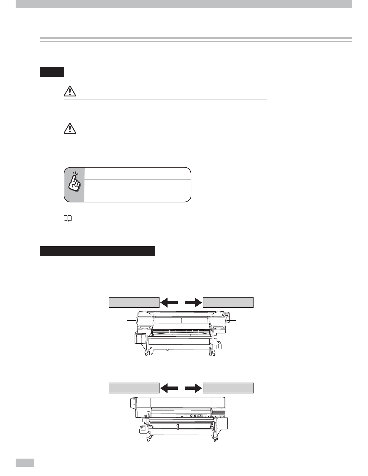
Capping unit side and wiping unit side
To identify the Printer’s right and left, this guide mentions the capping unit side and wiping unit side as follows.
Viewed from the Printer’s front (media teke-up side)
Viewed from the Printer’s rear (media supply side)
Capping unit sideWiping unit side
Capping unit side Wiping unit side
Capping unit is equipped.
Wiping unit is equipped.
Manual legend (Notational rules)
Page 17
17
This is the example page for the operation guidance.
INK MEDIA REG
MEDIA M.ADV
Operation Guide’s quick index
The quick index on the right edge is a
shortcut for users to access the target page.
Shows the LCD on the operation panel.
Shows that the LCD menu automatically
changes in the arrow direction without key
operation.
Shows that the LCD menu changes
in the arrow direction with key operation.
Page 18
Océ 6407 Basic Operation Guide
18
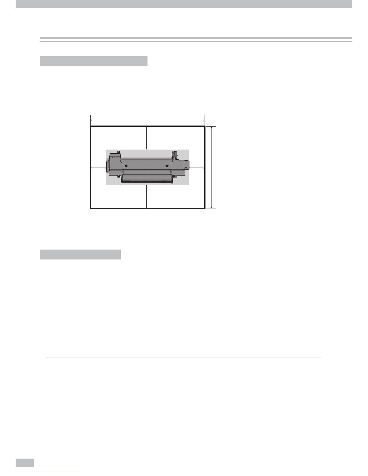
Installation and maintenance space
Adequate space is required around the Printer for supplies replacement of consumables and parts, print
processing, and ventilation during normal operation and maintenance.
Keep the space shown in the gure below.
4183mmormore
400
1000
1000
3275mmormore
(Front side)
400
Secure 2200 mm in horizontal direction.
(Unit: mm)
Environmental conditions
Operating temperature and humidity levels
Use the Printer within the temperature and humidity levels shown below.
Temperature: 15°C to 30°C (60°F to 80°F)
Humidity: 30% to 70%
To obtain better print quality, use the Printer within a temperature range of 20 to 25°C (68 to 77°F).
To ensure a stable and good print quality, the Printer slows down the print speed when the head
temperature exceeds 40°C (104°F).
NOTE
- If the Printer is not used at the operating temperature and humidity ranges, the print may be stopped or the print quality may be
degraded.
- It takes time for the Printer to reach the operating environment temperature and humidity.
- To ensure good print image quality, it is recommended to keep the room temperature 20 to 25°C, 68 to 77°F and use the Printer
after 1 hour.
Operating conditions
Page 19
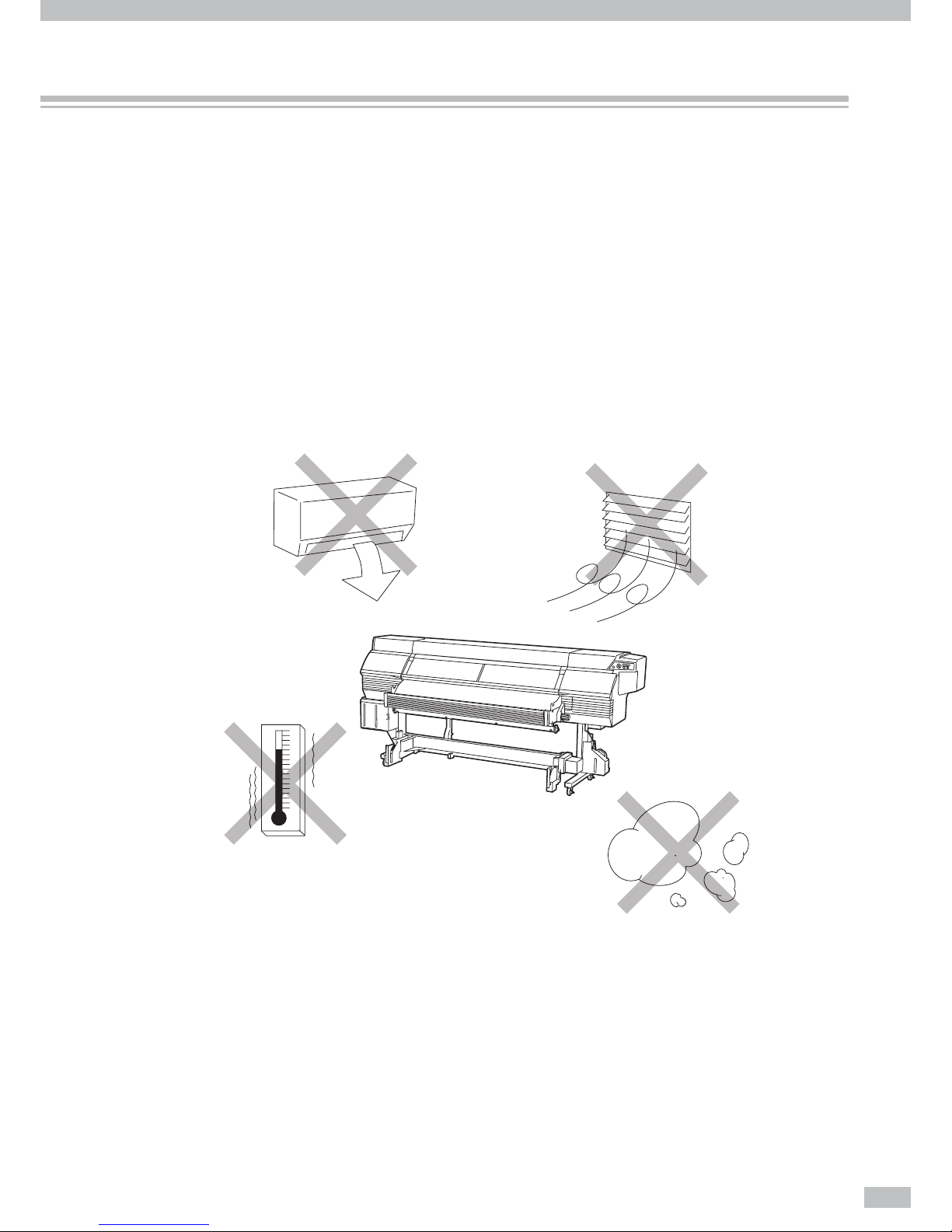
19
Places where the Printer must not be installed
Do not install the Printer in the following places.
Places near re
Places exposed to direct sunlight
Places subject to vibration
Places with excessive dust
Places subject to extreme changes in temperature or humidity
Places near an air conditioner or a heater
Places where the Printer may get wet
Places exposed to direct exhaust air from an air vent
Places near a diazo copier that may generate ammonia gas
Places with poor ventilation
Unstable places
Page 20
Océ 6407 Basic Operation Guide
20
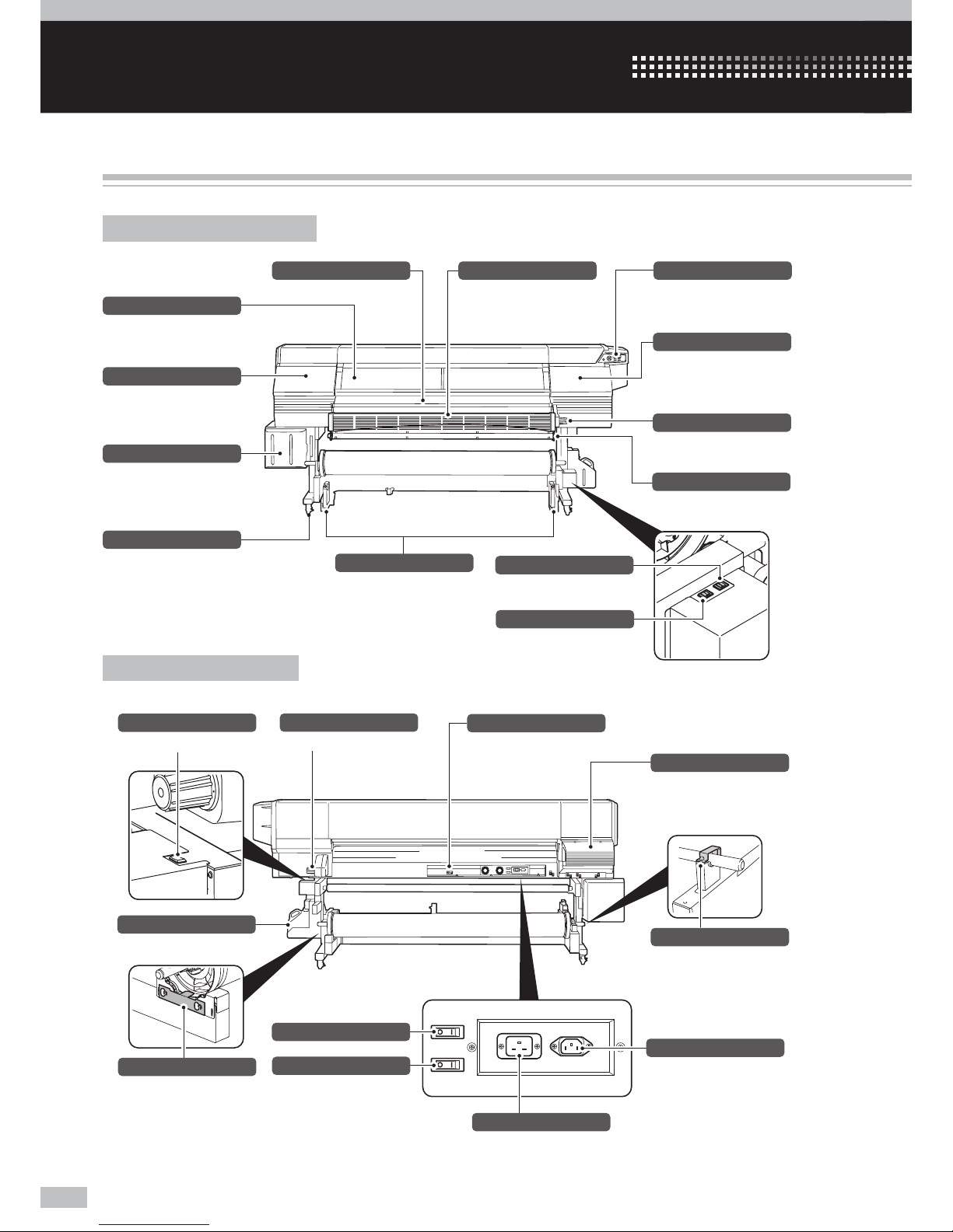
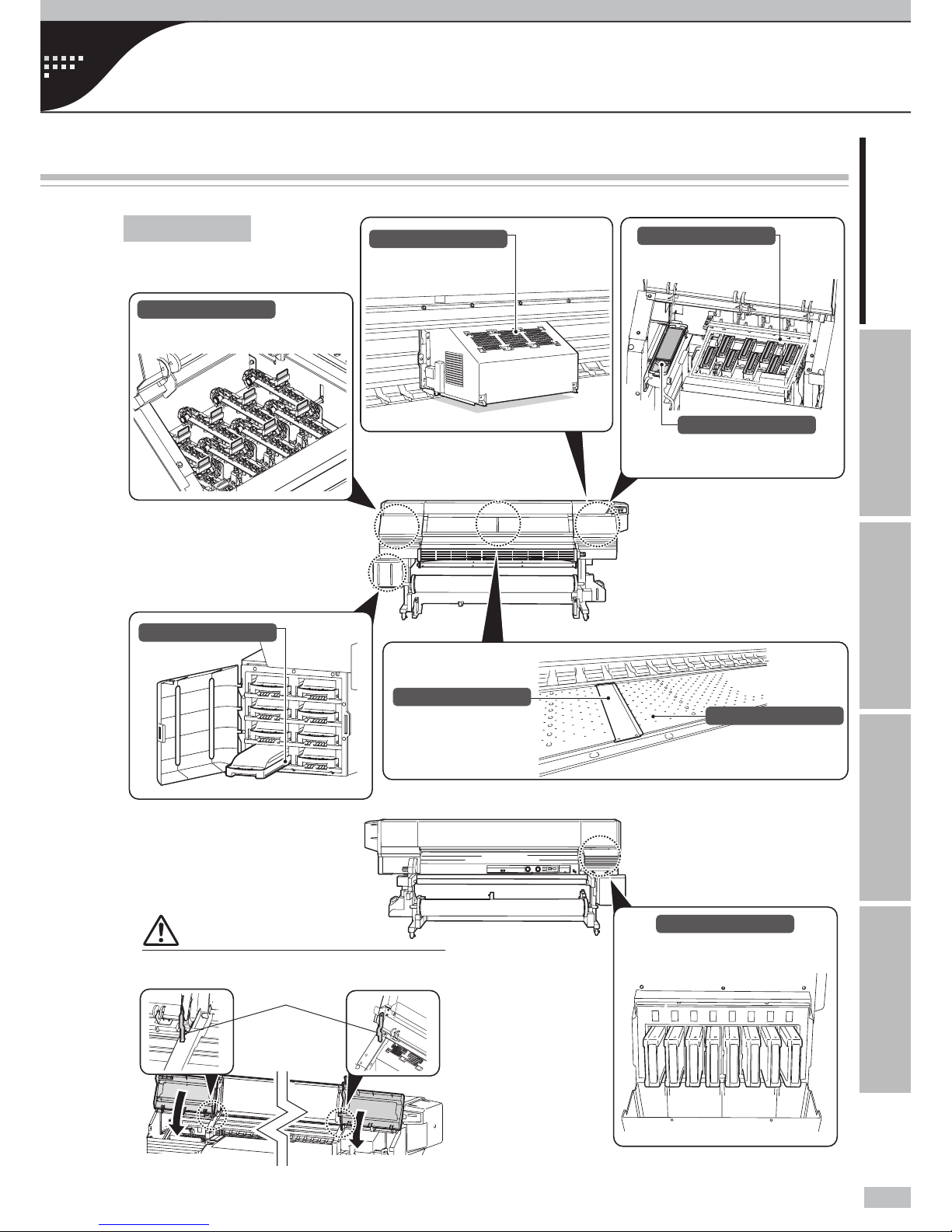
Appearance / Main components and their functions
Printer front (take-up side)
Operation panel
Provided with LEDS and LCD to
display printer status and keys to
set functions.
Media drying fan
Equipped to dry ink after printing.
Pressure control knob
Switches the media pressure force.
Take-up direction switch
Selects a media take-up direction.
Media advance/rewind switch
Advances or rewinds media.
Media advance/rewind switch
Advances or rewinds media.
Flange holder
Holds the scroller ange so that
the scroller ange would not lifted
during the print.
Shaft holder
Holds the scroller shaft so that the
scroller shaft would not be lifted
during the print.
Subcartridge cover
Covers the subcartridge insertion
slots.
On the LCD, subcartridge is
displayed as subtank.
Waste ink bottle unit
Contains a waste ink bottle
Capping cover
Opened when cleaning the
capping unit or the carriage.
Wiping cover
Opened when replacing the wiper
blade.
Protection bar
Placed to protect media surface
just after the print.
Front cover
Must be closed during printing.
Caster
Unlocked to move the Printer and
locked to immobilize it.
Tension bar guide
Applies tension to the media.
Tension bar
Placed to apply a proper tension to
media.
Printer power inlet
Printer power switch
Heater power inlet
Heater power switch
USB connector
Connected to the printer server.
Pressure control knob
Switches the media pressure force.
Ink box cover
An inlet to set ink (Note: Displayed
as “INK COVER” on the LCD.)
Printer rear (supply side)
Introduction
Page 21
21
Introduction For your basic operation Maintenance When encountering a problem Appendix
Appearance / Main components and their functions / Online and o ine / Supported media
Printer interior
Printer front (take-up side)
Printer rear (supply side)
Stopper
CAUTION
Be sure to unlock the stopper before closing the wiping
cover and capping cover.
Wiping unit
Removes foreign substances on
the print head’s nozzle surface.
Capping unit
Prevents the print head’s nozzles
from drying.
Spittoon case
For the stable printing, contains
the absorbers to hold excess ink
from print head.
Carriage
Houses the print heads inside, and
prints image with scanning media.
Ink tray
Supports ink pack setting.
Subcartridge
Provides with ink for printing while
ink pack is replaced.
On the LCD, Subcartridge is
displayed as subtank.
Media edge guard
Protects print heads from being
damaged by the curling or
feathering media edge.
Platen
Transports media.
The platen incorporates suction
fans and print heater to cure the
ink.
Page 22
Océ 6407 Basic Operation Guide
22
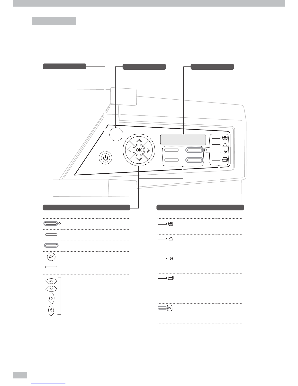
Operation panel
The keys, LEDs and LCD are laid on the Printer's operation panel of the Printer as shown below. In addition, the
operation panel is also equipped with a buzzer function for attention in case an error occurs or an invalid key is
input.
MENU
ONLINE
HEATER
CANCEL
ONLINE
HEATER
MENU
CANCEL
ONLINE
Power switch
Turns on or o the power of the
Printer.
LCD
Indicates printer status and menus.
Buzzer
Sounds when:
- An error occurred.
- Invalid key operation was made.
- The print head was not capped in
the daily maintenance.
LEDs
Indicates printer status with ON, OFF, and blinking.
Keys
Assists your menu operation and the Printer operation.
Data LED
(Green)
Error LED
(Orange)
Ink LED
(Green)
Media LED
(Green)
ONLINE LED
(Green)
Indicates data reception state.
Blink: Receiving data from the host computer.
OFF: No receiving data from the host computer.
Indicates whether an error has occurred.
ON: An error has occurred.
Blink: Warning state.
OFF: Normal (no error)
Indicates whether ink is remaining.
ON: Ink of all colors is present.
Blink: Ink near-end (Ink of any color is little.)
OFF: No ink.
Indicates whether media is remaining.
ON: Media is present (Either roll media or
cut-sheet media is loaded.)
Blink: Take-up reel unit's operation was
suspended.
OFF: No media (Neither roll media nor cut-sheet
media is loaded.)
Indicates online or offline state of the Printer.
ON: Online
Blink: Online pause mode
OFF: Offline
Selects online or offline of the Printer.
Switches between menu group screens, as
auxiliary parameter input.
Cancels entered parameters.
Determines the selected menu and parameters.
Enters heater control menu.
Selects a menu group and switches menu by
going up or down in a menu or option, or by
increasing or decreasing a value.
Page 23
23
Introduction For your basic operation Maintenance When encountering a problem Appendix
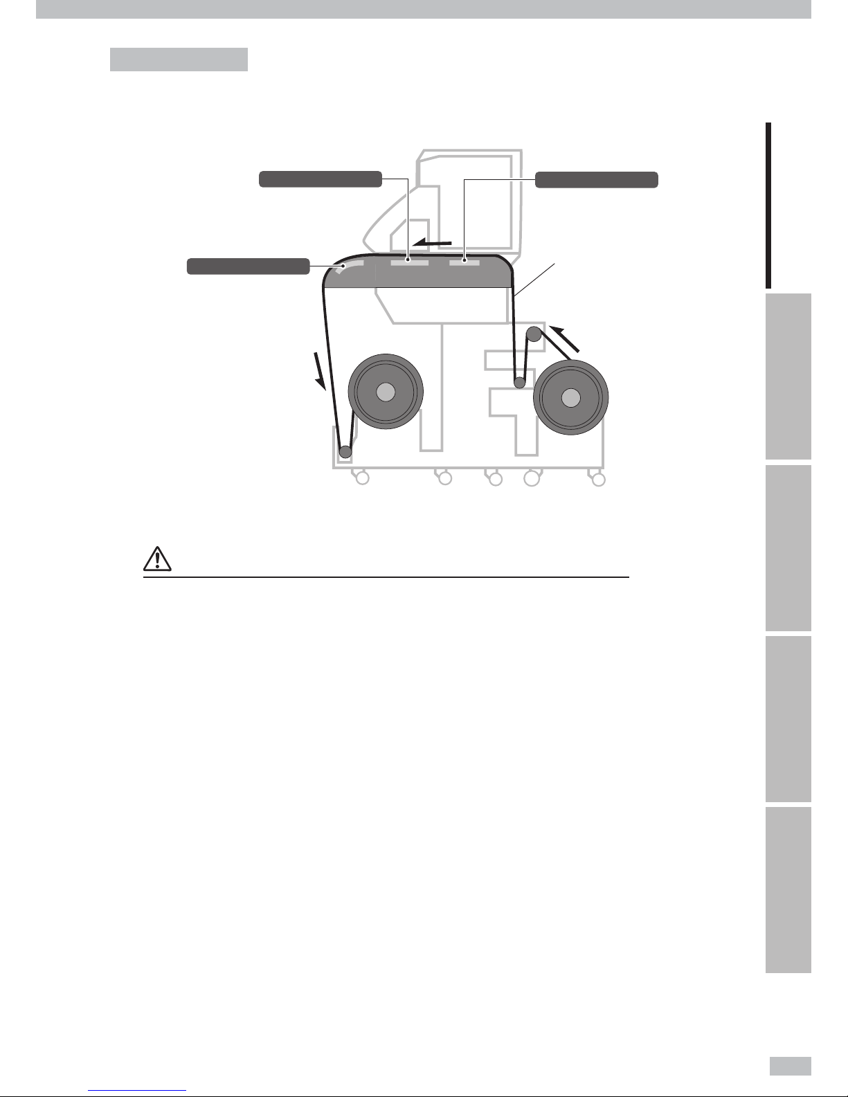
Printer heater unit
The printer is equipped with three heaters for ink fusing and image quality stabilization.
Preheater (rear)
Preheats media.
Media
Print heater (front)
Penetrates ink into media to fuse
the ink.
Afterheater (finishing)
Dries ink to stabilize print quality.
* These three heaters are controlled independently.
The temperature of each heater can be controlled from the operation panel and the host PC (RIP).
WARNING
- Do not touch these heaters to avoid burn as they become hot.
Page 24
Océ 6407 Basic Operation Guide
24
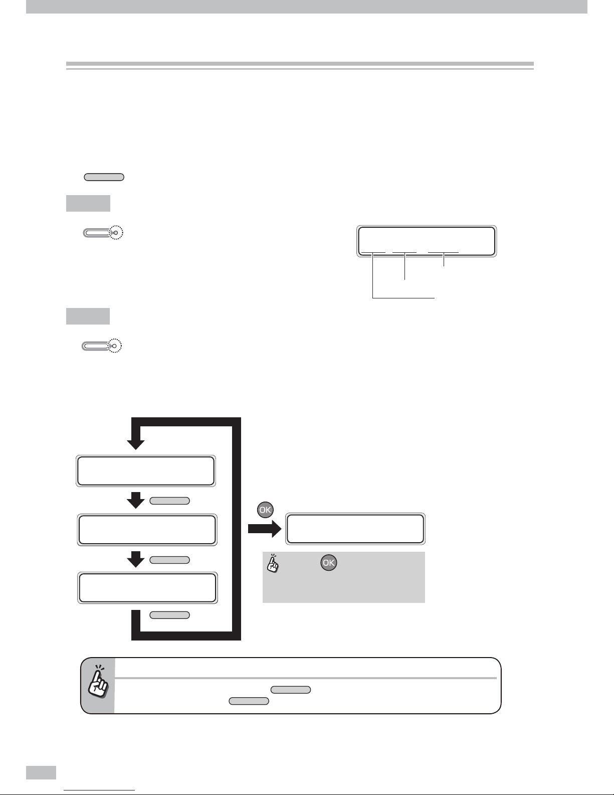
Online and o ine
The Printer operates in both online and o ine.
When the Printer is in online:
- The Printer prints the data sent from the computer’s Raster Image Process (RIP) software.
When the Printer is in o ine:
- The menu is operated with the operation panel keys.
The
ONLINE
key switches between online and o ine.
Online
When the online LED is on, the Printer is online.
O ine
When the online LED is o , the Printer is o ine.
The Printer in o ine displays the menu group on the LCD, and activates the menu operation.
The menu operation assists you to create new media presets, perform daily maintenance, and adjust the print
head settings.
When an operator call error is displayed...
- To activate the menu operation, press the
ONLINE
key.
* However, in some cases the
ONLINE
key does not activate the menu operation.
ONLINE
ON
ONLINE
OFF
MENU
MENU
MENU
When the key is pressed in any
menu group, the PH.REC MENU screen
opens.
INK MEDIA REG
MEDIA M.ADV
ハ゛ックフーィト゛ フィート゛
クリーニンク゛ サーヒ゛ス
ファンクション システム
メカチョウセイ ヒータ
REWIND FORM FEED
PH.REC PH.MAIN
PRINTER SETUP
ADJUST HEATER
#PH RECOVERY
>NORMAL
Online state (idle mode) display
Media name:PAPER
Media of 1625 mm (64 inches) width
Roll media is set
PRINTER READY
ROLL: 1625 / PAPER
Page 25

25
Introduction For your basic operation Maintenance When encountering a problem Appendix
Vinyl
Vinyl is media with PVC-material surface. As a general vinyl is adhesive-backed, by peeling the release paper on
the back you can stick the media easily. Depending on its gloss grade, the vinyl is classi ed into three: glossy vinyl
(with high gloss), matte vinyl (with no gloss), and semi-glossy vinyl (with medium gloss).
When the media is applied on some prints, a gray adhesive-backed vinyl is e ective to avoid the prints seen
through the top media.
For backlit purpose application, the PVC material surface is sometimes transparent or translucent.
Banner
Banner is polyester ber cloth media with double sides coated with synthetic resin lm such as PVC. As the
banner is water- and tear-resistant, it is applied for tent canvases, construction wrap sheets, and inkjet-printed
banner advertisements.
Depending on its gloss grade, the banner is classi ed into three: glossy banner (with high gloss), matte banner
(with no gloss), and semi-glossy banner (with medium gloss).
Mesh banner
Mesh banner is perforated banner media reinforced with mesh grid. As its open structure allows wind to
permeate, the mesh banner is wind- and tear-resistant, and will withstand heavy wind.
Backlit banner (FF)
Backlit banner, exible face (FF) is translucent, that is, semi-transparent banner media. With its translucency, it is
applied to the backlit sign inside a light box.
Compared with an acrylic sign, the backlit banner is lightweight and easy to handle, wind- and tear-resistant, and
of high safety and shutter proof withstanding wind pressure.
Solvent printing coated paper
Solvent printing coated paper is media with the printing surface coated on which solvent ink is cured vividly. Its
thickness depends on the product type.
When the media is applied on some prints, a blue back type is e ective to avoid the prints seen through the top
media.
Visit Océ on the internet at http://mediaguide.oce.com for the latest information.
Supported media
Page 26
Océ 6407 Basic Operation Guide
26
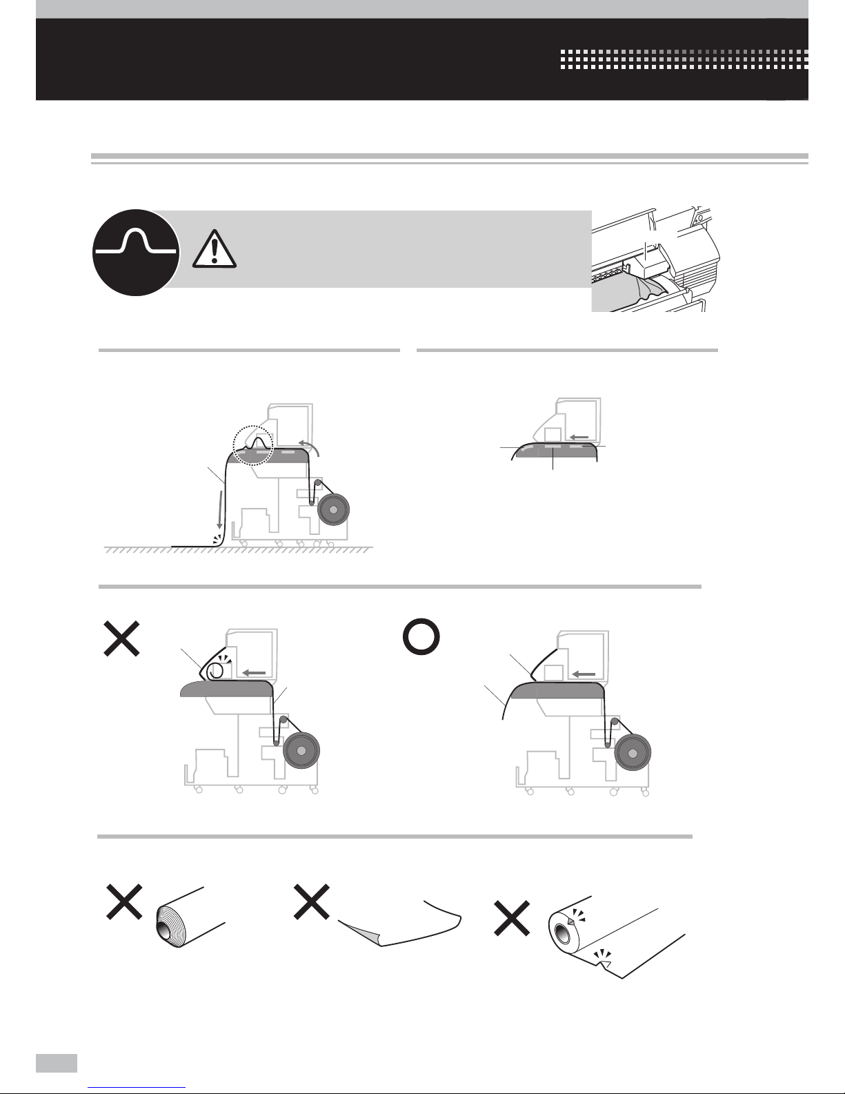
For your basic operation
Note that the media on the platen may bunch up
when the front media edge reaches the oor.
To avoid media wrinkle, turn o the preheater and
printheater.
At printing on paper-based media
At setting media
At printing without winding
If media waves, the sliding carriage may touch the
wave, which may damage the Printer.
Media bunches up.
Media
Media
wave
Carriage
Printheater
Preheater
OFF
OFF
Afterheater
Set the media so that the front media edge precedes the front cover.
Media
Front cover
Front cover
Media
OKNG
At visually checking media
Avoid using the media below.
The media was wound telescopically.
The right or left media edge curls. The media edge is deformed by, for
example, hitting media
NG NG
NG
Precautions to prevent media jams
The precautions below are recommended to prevent the main causes of media jams: media wave and skew.
Page 27
27
Introduction For your basic operation Maintenance When encountering a problem Appendix
Precautions to prevent media jams / Basic operation for printing / Procedure to remove media roll from the Printer / To print
on other media / To perform double-sided printing
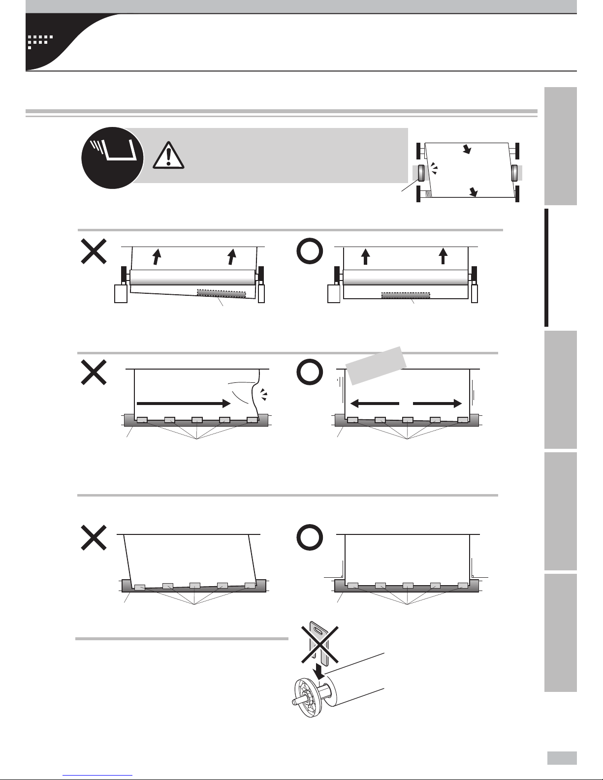
At the both media supply side and media take-up side,
without a ange spacer, x the scroller ange to the
media by pressing it as far as it goes.
At taking up media in LOOSE winding mode
Set the tension bar at the media center.
If the media is not perpendicular to the paper tube, the media is taken up with skew, which may cause the
media wave on the platen.
At attaching media to the take-up paper tube,
Be sure to set the media perpendicular to the take-up paper tube.
Media
Tension bar
Paper tube
Tape
Perpendicular
Perpendicular
Paper tube
Tape
Paper tube
Tape
Paper tube
Tape
Media
Tension bar
Skew
OK
NG
OK
NG
At xing media to the take-up paper tube,
Stick the adhesive tape from center outward.
垂直
OK
NG
④②①
The tape is stuck from center outward.
The
media
slacks
③⑤
垂直
①②③
The tape is stuck from media edge.
④⑤
If media skews, the media edge is disengaged
from the media edge guard, which may cause
the media wave.
Media edge guard
Media
[Viewed from top]
Media
Media
Media
Media
The media is
tightened.
Flange spacer
Page 28
Océ 6407 Basic Operation Guide
28
Basic operation for printing
Printing work ow overview
2
3
6
10
11
5
7
8
9
4
FRONT
REAR
REAR
REAR
1
1m
♪
FRONT
FRONT
FRONT
FRONT
FRONT
FRONT
CHECKEDGEGUARD
*O K ?
SELECTMEDIA
ROLL/SHEET:ROLL
…
SELECTMEDIA
MEDIA:Banner
SELECTMEDIA
MEDIA:PAPER
SETREMAININGMEDIA
****m
CHECK
SLACKENMEDIA
Blip
Blip
Feedmediafor
1m
moreaftertheblip.
♪
SETMEDIA
*O K ?
PREPARINGMEDIA
PLEASEWAIT
Page 29
29
Introduction For your basic operation Maintenance When encountering a problem Appendix
1
9
10
8
7
3
2
4
5
6
1
3
3
1
2
2
FRONT
FRONT
FRONT
FEEDINGMEDIA
FEEDINGMEDIA
OFF
Page 30
Océ 6407 Basic Operation Guide
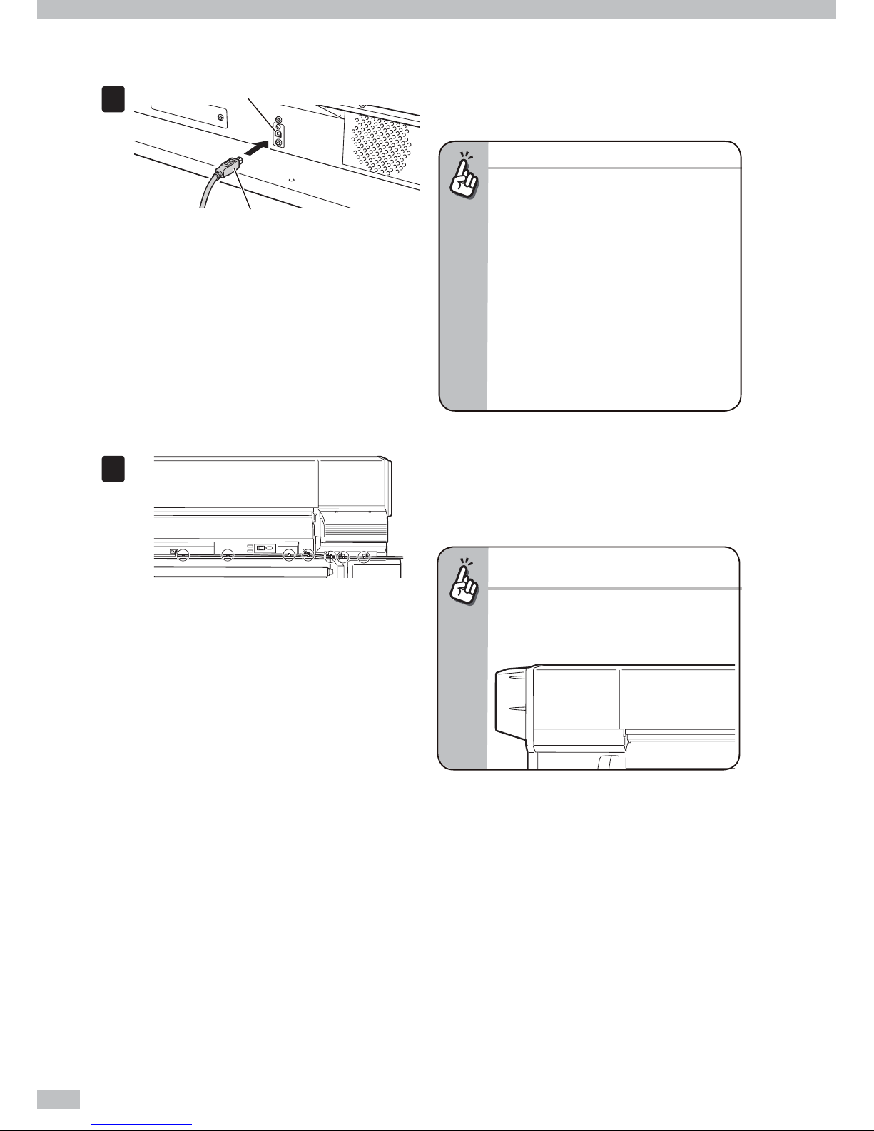
30
To connect USB cable.
1
USB connector
USB 2.0 cable (B-type connector)
Connect the Printer’s USB 2.0 cable to the USB
connector at the rear center of the Printer.
Important!
- Use the supplied USB 2.0 cable.
- For the USB connection and the related
system, use the USB-compliant hubs and
cables supporting USB 2.0. Note that a normal
operation may not be ensured if the habs,
cables, and the other related devices are not
USB-compliant.
- Use 5m cable or shorter. If the connection
length exceeds 5m, apply hubs to extend the
connection. The hub quantity must be ve
or less in total. Note that a normal operation
may not be ensured if a cable exceeding 5m is
applied, or if the cable connection exceeds 5m
without hubs.
2
Clamp the USB 2.0 cable to the Printer along
the wiping unit direction.
To protect the USB connector, clamp the USB 2.0 cable
to the Printer body as shown in the left gure.
To extend the cable along the capping unit
direction...
- As the gure below shows, x the cable at
some positions with adhesive tape. If the USB
cable is not clamped, the media feed sensor
may operate incorrectly.
Page 31

31
Introduction For your basic operation Maintenance When encountering a problem Appendix
Turn the Printer on.
With the procedure below, supply the power to the Printer’s two 200V power system.
CAUTION
- Do not use any power cable other than those supplied with the Printer.
- The supplied power cables are for 200 VAC only. Note that the plug shape di ers from that for 100 VAC.
- Be sure to secure the power cables with cable clamps. Otherwise, they may be caught by the feed unit resulting in
electric shock or damage to the Printer.
Turn the printer power and heater power switches on only before your rst operation. From the next operation, turn the
Printer on and o only by pressing the POWER switch on the operation panel.
1
Switch o (O) Power inlet
With the two power cords supplied with the
Printer, connect the Printer’s two power inlets
and the power supply’s two sockets.
Be sure to con rm that at the rear of the Printer the
printer power switch and heater power switch are set
to o , the side marked with O.
2
Clamp the two power cords to the Printer.
To protect the power cords, be sure to clamp them.
Printer power switch + Printer power inlet
Heater power switch + Heater power inlet
Supply side
Page 32

Océ 6407 Basic Operation Guide
32
3
Switch on (I)
Set the printer power switch and heater power
switch to on, the side marked with I.
4
MENU ONLINE
HEATER CANCEL
Power ON/OFF switch
Booting up...
INITIALIZING...
PLEASE WAIT
LOAD MEDIA
Press the power switch on the operation panel.
When the power switch is turned on, the Printer
performs the power-on self-diagnostic test and
displays the following message on the operation
panel.
If an error message appears...
- To recover the error, refer to “When
encountering a problem.”
- If the POWER LED on the operation panel does
not light even when the printer and heater
power switches at the rear of the Printer and
the power ON/OFF switch on the operation
panel are turned on, the power supply has a
problem.
CAUTION
Except for emergency, turn o the power while a message "PRINTER READY" is displayed. If the power is turned o
unnecessarily when the Printer is performing "INITIALIZING..."or "CLEANING," the ink may drool, the print head may be
damaged, or saved parameters may be lost.
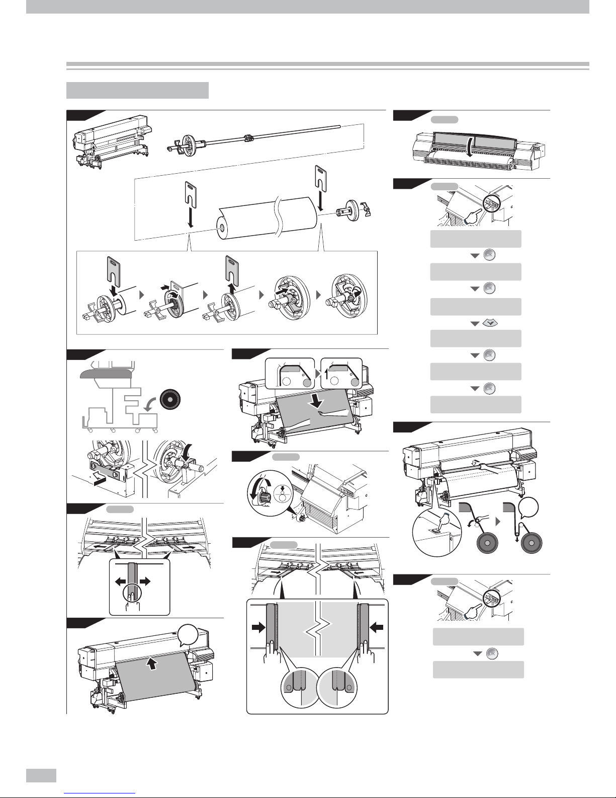
To load media on the Printer
This section uses banner to explain the media loading procedure.
1
Put the media on the table.
Page 33

33
Introduction For your basic operation Maintenance When encountering a problem Appendix
2
Load a roll media onto the scroller ange and scroller shaft.
Check the flange
spacer’s correct position.
(3) Remove the ange spacer.
(2) Push the scroller ange until it
stops and turn the handle
clockwise until the ange is
xed to the paper tube.
(5) Cover the scroller ange’s
convex part with the ange shaft
xture, and push the ange shaft
xture as far as it goes.
(5) Turn the knob to x the scroller
shaft.
(1) Insert the ange spacer
between the scroller ange and
the media roll.
The ange spacer should
be inserted to the
position indicated by the
line B.
Be careful not to deform
it by applying too much
force.
Handle
Flange shaft fixture
Flange shaft fixture
Convex part
Flange shaft fixture
Flange shaft fixture
Fixture
A
B
Move the roll spacer to the media center, and fasten
the fixtures at the roll spacer’s both sides.
Pass the scroller shaft through the roll spacer with fixtures at its
both sides, scroller flange, and flange shaft fixture.
The roll spacer prevents the
paper tube from bending at
the center due to the media
weight.
Scroller flange
Scroller flange
Scroller shaft
Scroller flange
Scroller flange
Scroller flange
Roll spacer
Roll spacer
Flange spacer
Flange spacer
Flange spacer
Not required in LOOSE
winding mode.
Not required in LOOSE
winding mode.
For outer take-up mode
For inner take-up mode
Roll media
Roll media
Page 34

Océ 6407 Basic Operation Guide
34
3
Capping unit side
Wiping unit side
Knob screw
Flange holder
Shaft holder
Remove the ange holder, and open the shaft
holder.
To open the shaft holder, loosen the knob screw.
4
Printer rear
Load the media roll into the Printer’s rear side
(supply side).
CAUTION
- As the media is heavy, carefully carry it with a recommended dolly.
- On carrying the media with two persons, carefully carry it by manually holding the scroller shaft.
- Be careful not to catch your nger or hand between the Printer and the scroller shaft.
Recommended dolly
Scroller shaft
On carrying the media alone: On carrying the media manually by two persons:
5
Capping unit side
Wiping unit side
Knob screw
Flange holder Shaft holder
Set the ange holder, and close the shaft holder.
After closing the shaft holder, fasten the knob screw.
6
Front cover
Protection bar
Remove the protection bar and open the front
cover.
Page 35

35
Introduction For your basic operation Maintenance When encountering a problem Appendix
7
Wipingunitside
Cappingunitside
With pressing the media edge
guard’s your side part, move each
media edge guard.
Move the media edge guards to each side.
Move the media edge guards to each side so that they
are not under the media.
With pressing the media edge guard’s your side part,
move each media edge guard.
8
Take-up side
Pressure control knobs
Set the pressure to “Open” by rotating the
pressure control knob.
9
Paper feeder
Printer rear
Insert the media end into the paper feeder,
while smoothing out the media by hand to prevent
wrinkles.
If the media is curled
- If it is hard to insert the media end into the
paper feeder due to a curl of the media,
interpose an interleaf and insert the media
end under the interleaf as shown in the gure
below.
Interleaf
Interleaf
Media
Media
- Upward curl - Downward curl
10
Blip
Feed media for 1m more after the blip.
♪
Platen
Feed the media for 1m more after the blip.
In this state, smooth out the media toward the both
sides on the platen to make the media center tense.
Point to be checked
- If the media is set with a distortion or wrinkles,
it may cause a media jam or skew.
Page 36

Océ 6407 Basic Operation Guide
36
11
Feed back the media.
Feed back the media while pressing the center of the
media gently at the supply side.
Con rm that the front media edge precedes the
closed front cover by approx. 30 cm.
30cm
Front cover
Important!
- This step is important to set the media properly.
12
Supply side
Set the pressure to “Normal” by rotating the
pressure control knob counterclockwise.
Point to be checked again
- Check that the media on the platen has no
wave or wrinkle.
13
With pressing the media
edge guard’s your side part,
move each media edge
guard.
Align each media edge
guard’s notch to the media
edge.
(1) (2)
Notch
Set the media edge guards.
(1) With pressing the media edge guard’s your side part,
move each media edge guard to the media edge.
(2) Align each media edge guard’s notch to the media
edge.
Check that the media edge guards are not under the
media or thick media is not caught by having been
inserted forcibly.
CAUTION
- The print operation without media edge guards may
cause a media jam.
14
Close the front cover, and set the protection
bar.
15
CHECK EDGE GUARD
✻
OK?
Press the key.
Page 37

37
Introduction For your basic operation Maintenance When encountering a problem Appendix
16
SELECT MEDIA
ROLL/SHEET:ROLL
Press the key.
17
SELECT MEDIA
MEDIA:PAPER
• • •
SELECT MEDIA
MEDIA:Banner
Select [Banner] and press the key.
With the or keys, select a media preset for
the current media type.
18
SET REMAINING MEDIA
✻✻✻✻
m
CHECK
SLACKEN MEDIA
Enter the remaining media length and press the
key.
When you do not know the remaining media length,
press the key without entering the length.
19
Adjust the tension bar l ength.
To print in TENSION winding mode: Conform the tension bar length with the media width.
The table below lists the tension bar combination and the tension bar’s total length. Referring to the list, apply
the tension bar length nearest to the media width.
To print without winding: The table below lists the tension bar combination and the tension bar’s total length.
Referring to the list, apply the tension bar length nearest to the media width.
Tension bar length
16inches(41cm)
S
L
48inches(123cm)
16inches(41cm)
S
ML
26inches(66cm)
Examples of tension bar combinations
Applied size Tension bar's length
S 16 inch (41cm)
ML 26 inch (66cm)
S, S 32 inch (82cm)
ML, S 42 inch (107cm)
L 48 inch (123cm)
ML, S, S 58 inch (148cm)
L, S 64 inch (164cm)
L, ML 74 inch (189cm)
When the tension bar is almost same as the media width, or is slightly longer than the media width, set the
tension bar with screws to the tension bar.
Media
Tension bar
ange with
screw
Tension
bar ange
with screw
Tension bar
Page 38

Océ 6407 Basic Operation Guide
38
When the tension bar is clearly longer than the media width, set the tension bar anges and xing rings to the
tension bar.
Media
Tension bar ange
+
Fixing ring
Tension bar
Tension bar ange
+
Fixing ring
20
Create a slack area in the media.
♪
Blip
Media advance/rewind switch
Tension bar
Peel roller
(1) Press the tension bar to the peel roller’s
upper part.
(2) By pressing the media advance/rewind
switch, create a slack area in the media.
Then, with slightly pressing the tension bar
in the direction of the media rear side, install
the tension bar in the slack.
Slacken o to a level lower than the supply-side slack
sensor.
When the slack reaches the sensor detection area, the
operation panel blips.
Peel roller
Scroller ange
Supply-side slack sensor
CAUTION
- Do not rotate the peel roller, or the Printer may be
damaged.
- Be sure to rotate the peel roller with the media
advance/rewind switch.
21
SET MEDIA
✻
OK?
PREPARING MEDIA
PLEASE WAIT
Press the key.
Page 39

39
Introduction For your basic operation Maintenance When encountering a problem Appendix
To load media on the take-up reel unit
This section explains the procedure, taking in TENSION winding mode for instance.
1
Load a paper tube onto the scroller ange and scroller shaft.
(4) Push the ange shaft xture as far
as it goes.
Handle
Flange shaft fixture
Flange shaft fixture
Fixture
Move the roll spacer to the paper tube center, and
fasten the fixtures at the roll spacer’s both sides.
Pass the scroller shaft through the roll spacer with fixtures at its
both sides, scroller flange, and flange shaft fixture.
The roll spacer prevents the
paper tube from bending at
the center due to the media
weight.
Flange spacer
Flange spacer
(1) Insert the ange spacer
between the scroller ange and
the paper tube.
(2) Push the scroller ange until it
stops and turn the handle
clockwise until the ange is
xed to the paper tube.
(3) Remove the ange spacer.
(5) Turn the knob to x the scroller
shaft.
Check the flange
spacer’s correct position.
The ange spacer should
be inserted to the
position indicated by the
line B.
Be careful not to deform
it by applying too much
force.
A
B
Scroller flange
Flange spacer
Flange shaft fixture
NOTE:
- To wind the media in LOOSE
winding mode, without inserting
the ange spacer, push the scroller
ange as far as it goes.
Scroller flange
Scroller shaft
Roll spacer
Scroller flange
Roll spacer
Paper tube
Flange spacer
Not required in LOOSE
winding mode.
Not required in LOOSE
winding mode.
Page 40

Océ 6407 Basic Operation Guide
40
2
Take-up direction switch
OFF
OFF
Set the take-up direction switch to OFF.
CAUTION
- If the Printer processing proceeds to the next step with the take-up direction switch set to ON, your hand may be
caught as the scroller is not secured.
3
Tension bar hook
Tension bar
Hook the tension bar to the tension bar hook
beforehand.
4
Load the paper tube in the Printer.
5
By pressing the key, feed the media until
the front media edge is wound on the paper
tube.
FEEDING MEDIA
Page 41

41
Introduction For your basic operation Maintenance When encountering a problem Appendix
6
Tape
Paper tube
Attach the media passed through the Printer to
the paper tube.
(1) Check the take-up direction, remove the slack of the
media, and then make sure that the media position
is not deviated on the supply side and the take-up
side.
(2) Attach the media to the paper tube with adhesive
tape. Tape it rst at the center, and then at the right
and left sides, so that the tension is uniform across
the media width and that no wrinkles are found on
the media. The taped positions are recommended to
be three or more in total.
Inner take-up:
Media is taken up with its print
surface coming inside.
Outer take-up:
Media is taken up with its print
surface coming outside.
Points to be noted on winding media
- If the media is not installed straight to the paper tube, a skew of media may occur.
- When the take-up direction is set as Inner take-up, the taken-up media's diameter increases and the media
cannot backfeed after printing. Select [FWD ONLY] beforehand in MEDIA BACK MODE of MEDIA REG MENU.
(When the media backfeeds in [BACK&FWD] mode, the motor idles and may cause a trouble.)
7
Take-up direction switch
OFF
u Outer take-up
- OFF
v Inner take-up
Set the take-up direction switch according to
the take-up direction.
8
By pressing the key feed the media, and
wind one full turn of the media on the paper
tube.
FEEDING MEDIA
CAUTION
- If the tension bar is attached without winding the
media by one turn, the tape will peel o .
9
Take-up direction switch
OFF
OFF
Again set the take-up direction switch to OFF.
Page 42

Océ 6407 Basic Operation Guide
42
10
Press the key to feed enough media to
create a slack.
FEEDING MEDIA
Be sure to create a su cient slack so that you can
install the tension bar at the bottom of the tension bar
guide.
11
Open the tension bar guide’s cover.
12
Place the tension bar at the bottom of the
tension bar guide.
When the tension bar does not reach the
tension bar guide’s bottom
- When the tension bar does not reach the
tension bar guide’s bottom, feed the media
with the operation panel’s FEED menu. Con rm
that tension bar was placed securely at the
tension bar guide’s bottom.
13
Close the tension bar guide’s cover.
When the excessive media slack is created
- If the media slack is secured excessively, the
take-up reel unit may keep winding the media
for more than the prescribed time, and a takeup timeout error occurs. In such a case, turn o
the take-up direction switch, and then press the
switch again.
14
Take-up direction switch
OFF
u Outer take-up
- OFF
v Inner take-up
Set the take-up direction switch according to
the take-up direction.
15
Input the data in the RIP software.
Page 43

43
Introduction For your basic operation Maintenance When encountering a problem Appendix
Procedure to remove media roll from the Printer
Media at take-up side
1
Take-up direction switch
OFF
OFF
Turn o the take-up direction switch.
2
Open the tension bar guide’s cover.
3
Place the take-up side tension bar at the
tension bar hook.
4
Cutter groove
Open the front cover, and then cut the media.
You are recommended to cut the media by setting the
cutter blade along the cutter groove.
Platen
Cutter
Cutter groove
Sponge
Cutter guide
Media
CAUTION
- A net is spread out on the supply side and take-up side paper guides respectively, so that the media will not adhere to
the guides. Do not remove these nets.
- When cutting the media, be careful not to damage the paper guide net.
- Pay attention not to drop the printed media to avoid smearing the media.
Page 44

Océ 6407 Basic Operation Guide
44
5
CLOSE
COVER
ONLINE
Set the Printer to o ine state by pressing the
ONLINE
key.
6
Ç
INK MEDIA REGÈ
Å
MEDIA M.ADV
Æ
ROLL(Banner)
1625mm
Press the key.
The media advance/rewind switch is activated by
selecting the media and setting the take-up reel unit’s
take-up direction switch.
7
Advance/rewind switch
Wind the media by pressing the takeup-side
take-up reel switch.
If the wound media diameter is so large that the media touches the media drying fan
- Move the media drying fan’s position with the procedure below.
Protection bar
(1) Remove the protection bar, and then open
the front cover.
Media drying fan
Knob screw
(2) Loosen the right and left knob screws next
to the movable media drying fan.
Media drying fan
(3) Pull the media dryer fan toward you, and
turn it upward by 90 degrees.
When the media drying fan is turned upward,
it slightly goes down and is xed. To return the
fan to its original position, pull it up and turn
it downward by 90 degrees toward you, and
then push and secure it with the knob screws.
- Turn the media drying fan carefully so that the media drying fan connecting cable does not hung up on
the pressure control knob and surrounding sheet metals.
Page 45

45
Introduction For your basic operation Maintenance When encountering a problem Appendix
8
Remove the tension bar from the tension bar
hook.
9
Knob screw
Tension bar hook
Loosen the knob screw of each tension bar
hook and extend it laterally.
10
Remove the media from the Printer.
CAUTION
- As the media is heavy, carefully carry it with a recommended dolly.
- On carrying the media with two persons, carefully carry it by manually holding the scroller shaft.
Recommended dolly
Scroller shaft
On carrying the media alone: On carrying the media manually by two persons:
Page 46

Océ 6407 Basic Operation Guide
46
Media at supply side
1
CLOSE
COVER
ONLINE
Set the Printer to o ine state by pressing the
ONLINE
key.
2
Ç
INK MEDIA REG
È
Å
MEDIA M.ADV
Æ
ROLL (Banner)
1625mm
Press the key.
The advance/rewind switch switch is activated by
selecting media.
3
(1)
(2)
(2)
Tension bar
<LOOSE widing>
Printer rear (supply side)
Tension bar
S size tension bar
Advance/rewind
switch
Peel roller
Remove the supply-side tension bar.
(1) By pressing the media advance/rewind switch, lift
up the slack part.
(2) Remove the supply-side tension bar.
CAUTION
- Do not rotate the peel roller manually with force, or
the Printer may be damaged.
4
Supply side
Set the pressure to “Open” by rotating the
pressure control knob.
Page 47

47
Introduction For your basic operation Maintenance When encountering a problem Appendix
5
Rotate the scroller ange manually to take up
the media.
6
Capping unit side
Wiping unit side
Knob screw
Flange holder Shaft holder
Remove the ange holder, and open the shaft
holder.
To open the shaft holder, loosen the knob screw.
7
Remove the media roll from the Printer.
CAUTION
- As the media is heavy, carefully carry it with a recommended dolly.
- On carrying the media with two persons, carefully carry it by manually holding the scroller shaft.
Recommended dolly
Scroller shaft
On carrying the media alone: On carrying the media manually by two persons:
Page 48

Océ 6407 Basic Operation Guide
48
Procedure to remove scroller ange from media roll
1
Recommended dolly
Rest a media roll on the table or on the
recommended dolly.
2
(1) (2)
Knob screw
Remove the scroller shaft xture at one side.
(1) Rotate the knob screw.
(2) Pull out the scroller shaft xture from the scroller
shaft.
3
①
②
Handle
Remove the scroller ange.
(1) Rotate and loosen the handle.
(2) Pull out the scroller ange from the scroller shaft.
4
Handle
At the other side, rotate and loosen the scroller
ange’s handle.
5
Supporting the scroller ange, pull out the
scroller shaft.
Page 49

49
Introduction For your basic operation Maintenance When encountering a problem Appendix
memo
Page 50

Océ 6407 Basic Operation Guide
50
To print on other media
To print on Vinyl, Mesh banner, Backlit banner (FF), or Solvent printing coated paper
Vinyl
Mesh banner
Install an S-size tension bar at the
slack center position.
(backed)
Printer setting
Media type: Glossy
For glossy vinyl
Install a tension bar conforming
with the media width.
TENSION
winding mode
LOOSE winding
mode
Supply-side tension bar
Supply-side tension bar
SELECT MEDIA
MEDIA:Glossy
Media type: Banner
SELECT MEDIA
MEDIA:Banner
# MEDIA BACK MODE
>01:BACK&FWD
Supply-side tension bar’s size
S size
Winding mode
LOOSE winding mode
Printer setting
Supply-side tension bar’s size
Length conforming with the
media width
Winding mode
TENSION winding mode
Media type: Matte MEDIA BACK MODE: BACK & FWD
# MEDIA BACK MODE
>01:BACK&FWD
MEDIA BACK MODE: BACK & FWD
For matte vinyl
SELECT MEDIA
MEDIA:Matte
Media
Media
Page 51

51
Introduction For your basic operation Maintenance When encountering a problem Appendix
TENSION
winding mode
LOOSE winding
mode
Media
Media
Install an S-size tension bar at the
slack center position.
Supply-side tension bar
Install a tension bar conforming
with the media width.
Supply-side tension bar
Printer setting
Supply-side tension bar’s size
Winding mode
Printer setting
Supply-side tension bar’s size
S size
Winding mode
LOOSE winding mode
# MEDIA BACK MODE
>01:BACK&FWD
Length conforming with the
media width
TENSION winding mode
# MEDIA BACK MODE
>01:BACK&FWD
Aft 50 Prn 40 Pre 45
C) 50 C) 40 C) 45
Backlit banner (FF)
Solvent printing coated paper
Media type: BLT_B
SELECT MEDIA
MEDIA:BLT_B
MEDIA BACK MODE: BACK & FWD
MEDIA BACK MODE: BACK & FWD Afterheater: 50°C / Printheater: 40°C /
Preheater: 45°C
Page 52

Océ 6407 Basic Operation Guide
52
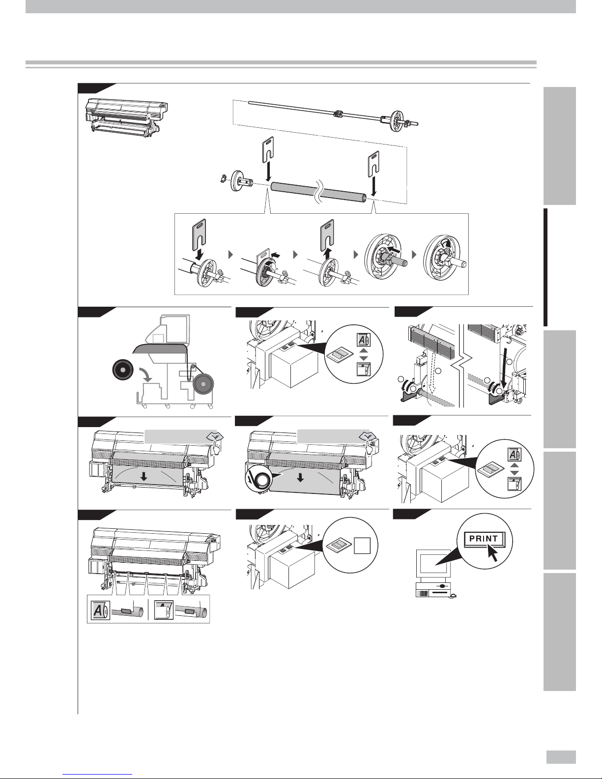
To take up media in LOOSE winding mode
CAUTION
- Apply the paper tube with the same length as the media width.
1
Paper tube
Scroller ange
Scroller shaft
Install the scroller shaft and scroller ange onto
the paper tube.
(1) Pass the scroller shaft through the roll spacer with
xtures at its both sides, scroller ange, and ange
shaft xture.
(2) Pass the scroller shaft through the paper tube.
(3) Insert the scroller anges into the paper tube’s both
edges as far as they go.
Scroller ange
Handle
(4) By rotating the handle x the scroller ange.
Knob screw
Flange shaft xture
(5) Cover the scroller ange’s convex part with the
ange shaft xture, and push the ange shaft xture
as far as it goes.
(6) Turn the knob screw to x the scroller shaft.
2
Take-up direction switch
OFF
Set the take-up direction switch to OFF.
CAUTION
- If the Printer processing proceeds to the next step
with the take-up direction switch set to ON, your
hand may be caught as the scroller ange is not
secured.
3
Install the paper tube into the Printer’s front side
(take-up side).
Page 53

53
Introduction For your basic operation Maintenance When encountering a problem Appendix
4
By pressing the key, feed the media until
the front media edge is wound on the paper
tube.
FEEDING MEDIA
5
Tape
Paper
tube
Install the printed media to the paper tube.
(1) Check the take-up direction, remove the slack of the
media, and then make sure that the media is not
deviated on the supply side and the takeup side.
(2) Attach the media to the paper tube with adhesive
tape. Tape it rst at the center, and then at the right
and left sides, so that the tension is uniform across
the media width and that no wrinkles are found on
the media. The taped positions are recommended to
be totally three or more.
Inner take-up:
Media is taken up
with its print surface
coming inside.
Outer take-up:
Media is taken up
with its print surface
coming outside.
Points to be noted on winding media
- If the media is not installed straight to the paper tube, a skew of media may occur.
- When the take-up direction is set as Inner take-up, the taken-up media's diameter increases and the media cannot
backfeed after printing. Select [FWD ONLY] beforehand in MEDIA BACK MODE of MEDIA REG MENU. (When the
media backfeeds in [BACK&FWD] mode, the motor idles and may cause a trouble.)
6
Take-up direction switch
OFF
u Outer take-up
- OFF
v Inner take-up
Set the take-up direction switch according to
the take-up direction.
7
By pressing the key feed the media, and
wind one full turn of the media on the paper
tube.
FEEDING MEDIA
8
Input the data in the software RIP.
Page 54

Océ 6407 Basic Operation Guide
54
To perform double-sided printing
At double-sided printing
- The Printer does not contain the structure to feed media with correctly applying the media advance adjustment value.
So the Printer cannot correctly align the rst side image with the second side image.
For convenience of explanation on the double-sided printing below, the side printed rst is referred to as the
"First side" and the side printed next is referred to as the "Second side." The following procedure is described for
the case to print the rst side of the media, reinstall the media to the roll feed unit for each media roll that wound
the media, and then print the Second side of the media.
First side printing
Second side printing
Move
Media roll moves
1
SELECT MEDIA
ROLL/SHEET:FACE
Load the media on the Printer.
For the procedure, see page 32.
At loading the media, on the operation panel select
[FACE] with the or keys.
Print the rougher side rst.
- With a single-sided-printing oriented banner,
the roughness grade is di erent between
the front and rear surfaces. To print on such a
banner, print on the rougher side rst as a rst
side.
2
F
o
u
r
f
u
l
l
t
u
r
n
s
Load the media onto the take-up reel unit.
For the procedure to load the media onto the take-up
reel unit, see page 39.
Wind four full turns of the media on the
paper tube.
- Since a margin of approximately 2.5 m or more
is required for the second side printing, wind
about four full turns of media to the take-up
reel unit in advance.
Page 55

55
Introduction For your basic operation Maintenance When encountering a problem Appendix
3
Start printing on the rst side of the media.
4
Reference dashed line
for cutting
Reference solid line to align print
position on rst and second sides
When printing is completed, open the front
cover and cut the media.
At the end of the rst-side printing, two lines are
printed. One line is a reference solid line to match print
positions on the rst and second sides. The other line
is a reference dashed line for cutting.
You are recommended to:
- To cut the media, insert the blade of a box
cutter into the gap between the platen and
the paper guide.
- To easily install the second side of media,
mark the position of the reference solid line
at the second side’s right and left edges.
CAUTION
- The drying time of printed media varies depending on printed images. Con rm that printed media has dried, and
then proceed to the next operation. Generally, dry the printed rst side for three hours or more (24 hours for highdensity print), and then start second side printing.
- Pay attention not to drop the printed media to avoid smearing the media.
5
Remove the supply side media roll from the
Printer.
See P. 43.
CAUTION
- As the media roll is heavy, carefully load or remove it
with a recommended dolly.
Recommended dolly
On carrying the media alone:
6
Move the media roll from
take-up side to supply side.
Remove the take-up side media roll from the
Printer, and move it to the supply side.
See P. 43.
Page 56

Océ 6407 Basic Operation Guide
56
Before starting the second-side printing...
- Go to the operation panel and change the settings of [#SUCTION FAN LEVEL] and [#MEDIA ADV MODE] in
accordance with the applied media. If the media is sticky or if the rst-side image may adhere to the platen,
the friction could be too high and the media advances irregularly. To solve it, set [#SUCTION FAN LEVEL] to
[LOW], and [#MEDIA ADV MODE] to [BACK & FWD1] or [BACK & FWD2].
#MEDIA ADV MODE
>01:BACK & FWD1
#MEDIA ADV MODE
>01:BACK & FWD2
Suction fan: [LOW]
Suction fan
MEDIA ADV MODE: [BACK & FWD1] or [BACK & FWD2]
To avoid the irregular media advance, set the
suction fan’s vacuum pressure to low.
[BACK & FWD1]
: At starting the print, the Printer moves the media back
and forth to prevent the media sticking to the platen.
[BACK & FWD2]
: When feeding the media after each scan, the Printer
moves the media back and forth to prevent the media sticking to the platen.
Media
Media
The Printer moves the media
back and forth to prevent the
media sticking to the platen.
#SUCTION FAN LEVEL
>01:LOW
7
Paper feeder
Printer rear
Insert the top edge of the media into the Printer.
With extending the media to eliminate the media
wrinkle, insert the media end into the paper feeder.
If the media is curled
- If it is hard to insert the media end into the
paper feeder due to a curl of the media,
interpose an interleaf and insert the media
end under the interleaf as shown in the gure
below.
Interleaf
Interleaf
Media
Media
- Upward curl - Downward curl
CAUTION
- The slanted or wrinkled media may cause media jam or
skew.
8
Reference solid line
Cutter groove
Align the reference solid line with the cutter
groove position.
If the line is not aligned at the right and left sides, align
it at one side rst and hold the position by hand, and
then align them at the other side while pulling the
media.
9
Take-up side
Pressure control knob
Set the pressure control knob to “Normal”.
Page 57

57
Introduction For your basic operation Maintenance When encountering a problem Appendix
10
Use the advance/rewind switch to create a slack inside the peel roller. Put the supply-side tension
bar on the slack of the media at the supply side.
See P. 37.
Printer rear (supply side)
Peel roller
Peel roller
Scroller ange
Tsnsion bar
11
CLOSE COVER
CHECK EDGE GUARD
✻
OK?
Set the media edge guards, and close the front
cover.
12
SELECT MEDIA
ROLL/SHEET:BACK
Select [BACK], and press the key.
With the or keys, select [BACK].
13
SELECT MEDIA
MEDIA:Banner
Select the media type.
With the or keys, select the media type.
14
CHECK
SLACKEN MEDIA
Check the media slack.
15
PREPARING MEDIA
PLEASE WAIT
- When the media setting is successfully completed, the
Printer returns to online or o ine state.
- If the media setting is not completed, an error message appears. Retry the procedure from step
7
.
The print head should be cleaned before starting
second side printing.
16
Start printing on the Second side of the media.
Check the RIP data.
- Note that the data transfer from the RIP di ers
by 180 degrees between rst side and second
side.
Page 58

Océ 6407 Basic Operation Guide
58
Daily maintenance
This section describes the regular inspection and maintenance procedures to be performed by users.
Maintenance
“X” appearing on the
tray prompts you to
replenish the liquid.
NGNGNG
OK
OK
OK
NGNGNG NGNGNG
Wiper blade
Wiper cleaning liquid
Capping unit
Spittoon absorber liquid
Carriage
Waste ink bottle
Clean the capping unit. Check the spittoon absorber liquid.
Check the wiper blade for contamination and wiper cleaning liquid level.
1
3
1
2
3
5
4
2
The use of gloves is recommended when performing cleaning and maintenance operations.
Always use genuine SIIT cleaning kits. These have been designed for maintaining high-quality imaging performance
and reliable printer operation. Using non-SIIT supplies may cause poor print.
Protrusion appearing on
the spittoon case
prompts you to replenish
spittoon absorber liquid.
An accumulated ink
prompts you to replace
the spittoon case.
P.60
" Check the wiper blade for contamination and
replenish wiper cleaning liquid "
P.61
" Clean the capping unit "
P.63
" Replenish spittoon absorber liquid "
Page 59

59
Introduction For your basic operation Maintenance When encountering a problem Appendix
NG
NG
NG
Gloves Cap cleaning liquid Wiper cleaning liquid Cleaning stick
+
Cleaning roller
Cleaning swab Spittoon absorber liquid
#TEST PRINTS
>NOZZLE PRINT
#PH RECOVERY
>NORMAL
#ヘット゛カク ニン
#ヘット゛カクニン
>
#RESEAT PRINTHEAD
>
Daily maintenance requires the consumables below.
6
5
7
8
4
Check the waste ink bottle’s ink level.
Check the media edge guards are
clean.
Print the NOZZLE PRINT pattern.
Clean the print head.
Check the print head surface is not
contaminated or smeared.
Daily maintenance / Cleaning / After today’s operation
P.64
" Check the waste ink bottle "
P.67
" Cleaning the madia edge guard "
P.64
" Clean the carriage "
P.68
" Performing normal cleaning "
P.68
" Print the nozzle print pattern "
Page 60

Océ 6407 Basic Operation Guide
60
Check the wiper blade for contamination and replenish wiper cleaning liquid
1
Open the front cover, and then open the wiping
cover.
2
Wiper blade
Wiper blade
Visually check the wiper blade for
contamination and scratches.
NGNGNG NGNGNG
If the wiper blade is stained or scratched, replace it.
See "Replace a wiper blade" on page 90.
3
Cleaning liquid port
Liquid level
Check the wiper cleaning liquid level.
Check that the cleaning liquid supply hole is at the top
face’s lower right of the wiping unit.
Wiper cleaning liquid
When the cleaning liquid level is lower than
the “
” mark’s top edge, replenish the wiper
cleaning liquid.
Replenish the liquid so that the cleaning liquid level is lower
than the “
” mark’s top edge.
4
Close the wiping cover and the front cover.
CAUTION
- Be sure to unlock the stopper before closing the wiping
cover. If you try to close the wiping cover without
unlocking the stopper, the stopper may bend, or the bent
stopper may touch the carriage, which may damage the
Printer.
Page 61

61
Introduction For your basic operation Maintenance When encountering a problem Appendix
Clean the capping unit
CAUTION
To prevent the ink dried inside the print head’s nozzles:
- Do not leave the Printer with the carriage detached from the capping unit.
- Within 5 minutes, complete the capping unit’s cleaning operation and cap the print head.
1
(1)
(2)
Attach the cleaning roller to the cleaning stick.
2
Ç
INK MEDIA REG
È
Å
MEDIA M.ADV
Æ
MENU
Set the Printer to o ine state and press the
MENU
key.
Ç
REWIND FORM FEED
È
Å
PH.REC PH.MAIN
Æ
Press the key.
3
#CAP CLEANING
>
Press the key.
4
#CAP CLEANING
✻
OK?
CARRIAGE MOVING
PLEASE WAIT
OPEN COVER
CLEAN CAP
Press the key.
The carriage moves to the wiping unit side.
The Printer issues an audio warning beep.
- When the carriage moves, the Printer issues an
audio warning beep.
To unactivate the warning beep, see the
Advanced Operation Guide.
5
Open the front cover and then open the
capping cover.
Page 62

Océ 6407 Basic Operation Guide
62
6
Soak the cleaning roller in the cap cleaning
liquid.
TIP
- To prevent the cap cleaning liquid
contaminated, in the cap cleaning liquid bottle
do not soak the cleaning roller after you clean
the cap with it.
7
CAUTION
- Be careful so that the cap cleaning liquid does not
adhere to any part other than the cap.
Clean the top surface of the cap by rolling the
cleaning roller.
(1)
Roll the roller back and forth on each cap.
(2)
Then roll the roller back and forth 10 times on each cap.
TIP
- The cleaning roller is intended for a single
use only. Use a new cleaning roller for each
cleaning.
8
Close the capping cover and the front cover.
The print head returns automatically to the home
position.
CAUTION
- Be sure to unlock the stopper before closing the capping
cover. If you try to close the capping cover without
unlocking the stopper, the stopper may bend, or the bent
stopper may touch the carriage, which may damage the
Printer.
The missing dots persist even after the cap cleaning...
- If you still see the missing dots even after the cap cleaning above, with checking visually remove foreign
matters and ink stains on the cap with a cleaning swab dampened with cap cleaning liquid.
Page 63

63
Introduction For your basic operation Maintenance When encountering a problem Appendix
Replenish spittoon absorber liquid
1
Ç
INK MEDIA REG
È
Å
MEDIA M.ADV
Æ
MENU
Set the Printer to o ine state, and press the
MENU
key.
2
Ç
REWIND FORM FEED
È
Å
PH.REC PH.MAIN
Æ
Press the key.
3
#CAP CLEANING
>
Press the key.
4
#CAP CLEANING
✻
OK?
CARRIAGE MOVING
PLEASE WAIT
OPEN COVER
CLEAN CAP
Press the key.
The carriage moves.
The Printer issues an audio warning beep.
- When the carriage moves, the Printer issues an
audio warning beep.
To unactivate the warning beep, see the
Advanced Operation Guide.
5
Open the front cover, and then open the
capping cover.
6
Spittoon sponge
Dropper
With a dropper, moisten the spittoon sponge
with the spittoon absorber liquid.
Page 64

Océ 6407 Basic Operation Guide
64
7
Spittoon unit
Liquid level
Protrusions
Pour the spittoon absorber liquid into the
spittoon case until the liquid level is as high as
the indication protrusions.
NOTE
- A few minutes after pouring the spittoon absorber
liquid into the spittoon case, the spittoon absorber
sponge absorbs the liquid and the liquid level is
lowered. In such a case, again add the spittoon
absorber liquid.
Check the waste ink bottle
Check the level in the waste ink bottle by visual inspection to
over ow. If the waste ink level is as high as [FULL] indication label,
replace the bottle with an empty waste ink bottle.
See " Replace a waste ink bottle " on the page 82 .
Clean the carriage
Some lint soaked with ink may adhere to the head guard and to the both sides of the head top section. Perform
cleaning to remove such lint frequently. Remove it carefully as it may smear the printout's surface.
Wipe dust o the platen.
1
Ç
INK MEDIA REG
È
Å
MEDIA M.ADV
Æ
MENU
Set the Printer to o ine state, and press the
MENU
key.
2
Ç
REWIND FORM FEED
È
Å
PH.REC PH.MAIN
Æ
Press the key.
3
#CAP CLEANING
>
• • •
With the key scroll to [#RESEAT
PRINTHEAD].
3
#RESEAT PRINTHEAD
>
Press the key.
Page 65

65
Introduction For your basic operation Maintenance When encountering a problem Appendix
4
#RESEAT PRINTHEAD
✻
OK?
CARRIAGE MOVING
PLEASE WAIT
OPEN COVER
RESEAT PRINTHEAD
CAUTION
To prevent the ink dried inside the print head’s nozzles:
- Do not leave the Printer with the carriage detached from the capping unit.
- Within 5 minutes, complete the capping unit’s cleaning operation and cap the print head.
Press the key.
The carriage moves.
The Printer issues an audio warning beep.
- When the carriage moves, the Printer issues an
audio warning beep.
To unactivate the warning beep, see the
Advanced Operation Guide.
5
Open the front cover and then open the
capping cover.
6
Spittoon unit
Knob screw
Remove the knob screw of the spittoon unit
and remove the spittoon unit.
CAUTION
- The spittoon unit contains cleaning liquid. Be
careful not to spill it.
7
Soak the cleaning swab in the cap cleaning
liquid.
TIP
- To prevent the cap cleaning liquid
contaminated, in the cap cleaning liquid bottle
do not soak the cleaning swab after you clean
with it.
- The cleaning swab is intended for a single
use only. Use a new cleaning swab for each
cleaning.
8
Manually slide the carriage to the position
where you removed the spittoon unit.
Page 66

Océ 6407 Basic Operation Guide
66
9
Carriage
To prevent the cap cleaning liquid
contaminated, in the cap cleaning liquid bottle
do not soak the cleaning swab after you clean
with it.
Dirt (gray parts)
Nozzle surface
<Head top section>
CAUTION
- Do not rub the head nozzle surface with a cleaning
swab. It may cause a Priner failure.
10
Carriage
Head guard
Clean the head guard at the right and left sides
of the carriage using a cleaning swab or a soft
cloth.
11
Knob screw
Spittoon unit
Move the carriage manually onto the platen
(left side) and secure the spittoon unit with the
knob screw.
12
Close the capping cover and then close the
front cover.
The carriage returns automatically to the home
position.
CAUTION
- Be sure to unlock the stopper before closing the capping
cover. If you try to close the capping cover without
unlocking the stopper, the stopper may bend, or the bent
stopper may touch the carriage, which may damage the
Printer.
Page 67

67
Introduction For your basic operation Maintenance When encountering a problem Appendix
Cleaning the madia edge guard
1
Open the front cover.
2
Dip a cleaning swab in the cap cleaning liquid.
TIP
- To prevent the cap cleaning liquid
contaminated, in the cap cleaning liquid bottle
do not soak the cleaning swab after you clean
with it.
- The cleaning swab is intended for a single
use only. Use a new cleaning swab for each
cleaning.
3
Checking visually, scrub stains on the media
edge guard.
4
Clean the stains with a soft and clean cloth.
5
Close the front cover.
Page 68

Océ 6407 Basic Operation Guide
68
Performing normal cleaning
1
Ç
INK MEDIA REGÈ
Å
MEDIA M.ADV
Æ
MENU
Set the Printer to o ine state, and press the
MENU
key.
2
Ç
REWIND FORM FEED
È
Å
PH.REC PH.MAIN
Æ
Press the key.
3
#PH RECOVERY
>NORMAL
Press the key.
4
#PH RECOVERY
✻
NORMAL
Press the key.
5
#SELECT: 87654321FB
✻
BOTTLE OK?
Press the key.
The indicated number denotes the head to be
cleaned.
6
#PH REC 87654321FB
✻
BOTTLE OK?
Press the key.
Check the level in the waste ink bottle by visual
inspection to over ow. If the waste ink level is as high
as [FULL] indication label, replace the bottle with an
empty waste ink bottle.
See "Replace a waste ink bottle" on page 84
#PH RECOVERY
✻
CLEANING 12 12
This value is counted down every 10 seconds.
Start the print head cleaning.
Print head cleaning takes several minutes.
When the cleaning starts, the required time is
displayed and the time is counted down every 10
seconds.
7
#PH RECOVERY
>NORMAL
Press the key.
The Printer returns to the o ine state, that is, menu
mode.
Ç
REWIND FORM FEED
È
Å
PH.REC PH.MAIN
Æ
Print the nozzle print pattern
Page 69

69
Introduction For your basic operation Maintenance When encountering a problem Appendix
Perform the NOZZLE PRINT every day before using your printer.
Use the nozzle print pattern to check that all print head nozzles are working correctly.
1
Ç
INK MEDIA REGÈ
Å
MEDIA M.ADV
Æ
MENU
×2
Set the printer to o ine state and press the
MENU
key twice.
2
Ç
PRINTER SETUP
È
Å
ADJUST HEATER
Æ
Press the key.
3
#TEST PRINTS
>NOZZLE PRINT
Press the key.
4
#TEST PRINTS
✻
NOZZLE PRINT
Press the key.
5
#TEST PRINTS
✻
OK?
Press the key.
#TEST PRINTS
✻
EXECUTING
6
Check for missing dots and incorrect print.
If missing dots are found in the nozzle print, perform the normal cleaning.
OK
NG
No missing dot is found,
and the printout is correct.
Missing dots or lines are
found.
Page 70

Océ 6407 Basic Operation Guide
70
Cleaning
Clean the exterior
If the Printer exterior is smeared, moisten a soft cloth with water or water-diluted neutral detergent, wring it, and
clean the exterior with the wrung cloth.
CAUTION
- Before cleaning the Printer exterior, be sure to turn o the printer and heater power supply switches.
- Never use volatile solvent such as thinner and benzene. The coating may come o or discolor.
Clean the front cover and front paper guide
If the Printer is smeared with dust and paper dust, remove them using a vacuum cleaner. If the contamination is
heavy, wipe it out with a soft cloth moistened with neutral detergent.
Front cover
Front paper guide
CAUTION
- Before cleaning the front cover and rear paper guide, be sure to turn o the printer and the heater
power switches.
- Do not blow o dust and paper dust as they may degrade print quality.
Carriage cleaning
Vacuum the dust o the carriage's fresh air inlet. Monthly cleaning is recommended.
Fresh air inlet
Carriage
Page 71

71
Introduction For your basic operation Maintenance When encountering a problem Appendix
After today’s operation
The Printer has an internal clock which allows it to wash the print heads automatically, ushing some ink through
the print heads, which keeps the print heads in good condition. To ensure the Printer’s automatic maintenance
operation, after today’s operation keep your Printer on the conditions below.
1. Never turn the Printer o .
2. Keep the front cover closed.
3. Take up the media on the Printer, or unload the media from the Printer.
If you keep the media loaded on the Printer for a long time, the media may be wrinkled on the platen or the
media gripping trace may be left. To ensure the media in good condition, the operation below is recommended.
Especially after printing on Vinyl, be sure to unload it from the Printer. Note that Vinyl is wrinkled so frequently.
With the media loaded With the media unloaded
OK
NG
MENU ONLINE
HEATER CANCEL
OK
NG
Page 72

Océ 6407 Basic Operation Guide
72
Before deciding that there is a serious problem with the Printer, check the following items.
Power is not turned on.
Items to be checked Corrective measures
zPower cable connection Check that the power cable is correctly plugged into the power outlet.
zPower supply to the outlet Supply power to the power outlet.
zPower switch on/o Turn on the power switch. See “Turn the Printer on.” on page 31.
The paper guide is not heated even when the heater is turned ON.
Items to be checked Corrective measures
zPrinter status The paper guide is heated during
Printing or when the heater is turned on with the heater control menu. Be sure the
paper guide is heated by printing the nozzle print pattern or set the heater to ON.
See the Advanced Operation Guide.
zHost computer RIP setting The heater temperature can be set also by the RIP of the host computer. Check the
host computer setting.
zHeater control menu Turn on the heater (afterheater/printheater/preheater) again, and then print nozzle
print pattern or forcibly set the heater to ON to check that the paper guide is heated.
See the Advanced Operation Guide.
zPower voltage Connect the Printer to 200 VAC power.
The printer fails to start or operate correctly.
Items to be checked Corrective measures
zERROR LED and LCD message
on the operation panel
See “When an error message is displayed” on page 76.
The Printer cannot print.
Items to be checked Corrective measures
zUSB cable connection Connect the USB cable correctly. See “To connect USB cable.” on page 30.
zERROR LED and LCD message
on the operation panel.
See “When an error message is displayed” on page 76.
zError LED OFF Print the nozzle adjustment pattern. See “Print the nozzle print pattern” on page 68.
(Con rm that the RIP software "Test pattern" is printed.)
zPrint head cleaning Clean the print head. See “Performing normal cleaning” on page 68.
Check your problem
When encountering a problem
Page 73

73
Introduction For your basic operation Maintenance When encountering a problem Appendix
Although the Printer is in the print mode, printing does not start with "PREHEATING" displayed on
the operation panel.
Items to be checked Corrective measures
zRoom temperature Raise the room temperature. (Recommended temperature: 20 to 25ºC)
zA ect of air ow If the air from the air conditioner or fan is blowing against the paper guide, avoid the
air ow (by changing air ow direction, orientation of the Printer, or the location of the
Printer).
The transmitted data is not printed.
Items to be checked Corrective measures
zONLINE LED ( ashing?) Check the communication conditions to the host computer.
Media jams occur frequently.
Items to be checked Corrective measures
zMedia type Check whether the media type setting matches the type of media loaded. See “To
print on other media” on page 50.
zMedia loading Install the media properly. See “To load media on the Printer” on page 32.
zObstructions in the carriage
path or the media path
Remove any obstructions. See “How to clear media jams” on page 75.
zSuction fan power If the suction fan power is not proper, reduce the power. See Advanced Operation
Guide.
zHeater temperature setting If the heater temperature is not best set, lower the heater temperature. See Advanced
Operation Guide.
Print quality is poor.
See Advanced Operation Guide.
Blank sheet appears.
Items to be checked Corrective measures
zPrint data Check the current print data to con rm that you sent the blank sheet's data.
Printing is slow.
The carriage sometimes moves.
Check your problem / How to clear media jams / When an error message is displayed / Out of ink while printing / The media was skewed.
/ Warning messages / Move the Printer / Replace a waste ink bottle / Install and replace an ink pack / Replace a spittoon case / Replace a
wiper blade
Page 74

Océ 6407 Basic Operation Guide
74
Items to be checked Corrective measures
zUSB connection speed When the data transmission speed is slow, the Printer waits for the data with the print
heads capped.
Check the USB’s transmission speed. If the USB is connected at full speed mode, the
speed is improved by changing the condition to connect to the computer as follows,
so that it is connected at high speed mode.
- Re-connect the USB cable.
- Connect the USB cable to the USB 2.0 port.
- Re-install the driver.
- Change the USB cable to the one supporting the high speed transmission.
-
If a hub is applied, change the hub to the one supporting the high speed transmission.
Printing is slow.
During print, print heads are capped frequently.
Items to be checked Corrective measures
zHigh-temperature environment If the Printer temperature is 40°C or more, the Printer prints at a lower printing speed.
Set the ambient temperature to 20 to 25°C (recommended temperature), and hold
the Printer for one hour or more. Then start printing.
zAdditionally connected device
transmitting enormous volume
of data
Remove the additional device connected to the USB.
Recommended system con guration
- Windows™ XP Professional (SP2)
- Dual-core, 2.0GHz or more
- Memory, 2GB or more
- HDD, 100GB or more
- 2-port USB 2.0, for Dongle and Printer
- DVD-ROM drive, to install the RIP software
zComputer’s speci cation Apply the computer containing the recommended system con guration below.
zComputer’s additional job
processing
Terminate the other application software, for example, anti-virus software.
You cannot understand the current operation panel display language.
Items to be checked Corrective measures
zLanguage setting Start with the Printer powered o . At the operation panel, press the
MENU
key and
hold it down. While holding the
MENU
key down, press the POWER switch and hold it
down. Continue to hold down both keys. Then the language selection menu should now
appear on the operation panel display. Highlight your preferred language with the
and keys, then press the key.
Page 75

75
Introduction For your basic operation Maintenance When encountering a problem Appendix
If the printer reports a media jam, follow these steps.
1
WARNING! X
CLEAR MEDIA JAM
X: Media jam type
Meaning
0: Media jam 0 A jam on the media feed path is invalidating the Printer's normal operation.
1: Media jam 1 A jam on the carriage is invalidating the Printer's normal operation.
2: Media jam 2 The media was not detected correctly because:
- Roll media or cut-sheet media was selected incorrectly.
- The length of the applied cut-sheet media is not as prescribed.
The message appears.
2
Pressure control knobs
Take-up side
OPEN COVER
REMOVE MEDIA
Rotate the pressure control knob, and set it to
“Open”, and then open the front cover.
3
Remove the jamnned media, make sure that no obstruction is left in the carriage path and the
media feed path, and then close the front cover.
At manually sliding the carriage...
- If the carriage must be moved manually, slide
the carriage by softly pressing the arrowed
parts.
4
CARRIAGE MOVING
PLEASE WAIT
Close the front cover.
The carriage moves to the home position.
5
Again load the media on the Printer. See "To load media on the Printer" on page 32.
How to clear media jams
Page 76

Océ 6407 Basic Operation Guide
76
When the ERROR LED lights up, check the message displayed on the operation panel display.
Error messages shown below are classi ed into two groups.
Service call errors:
Errors that the operator (customer) cannot recover, such as hardware/software failures. Contact your service
representative.
Operator call errors:
Errors that the operator (customer) can recover.
To recover the error, follow the advice described here.
Service call errors
Restart the Printer.
- If a service call error appears, restart the Printer by turning o and on as follows. Then the error may often
be recovered.
(1) Turn of the operation panel’s POWER switch and the Printer rear’s printer power switch and heater power
switch.
(2) Remove the two power cords from the socket, then at the Printer rear remove the two power cords from the
printer power inlet and the heater power inlet.
(3) Hold the Printer for one minute or more.
(4) Connect each power cord above to its inlet, then connect the two cords to the socket.
(5) Turn on the all three switches above.
(System error)
SYSTEM ERROR nnnn
POWER OFF/ON
nnnn: Error code
Meaning An unrecoverable error occurred.
Action Contact your service representative, and inform them of the
displayed error code.
Operator call errors
The following errors are recover by the operator.
(Ink errors)
CLOSE INK COVER
Meaning The ink cover is open.
Action You are advised to follow the message.
OPEN INK COVER
XXX LOAD INK PACK
XXX: Ink color/location
Meaning An ink pack is not installed.
Action You are advised to follow the message.
If this message appears when the speci ed color’s ink pack is
installed, the ink pack installation may not be proper. Check that it
is installed properly.
When an error message is displayed
Page 77

77
Introduction For your basic operation Maintenance When encountering a problem Appendix
CHECK nn
XXX INK PACK
nn: Ink error code
XXX: Ink color/location
Meaning A problem occurred with an ink tray, or a genuine ink pack was
not identi ed.
Action You are advised to follow the message.
Write down the displayed error code.
OPEN INK COVER
XXX REPLACE INK CART
XXX: Ink color/location
Meaning The ink pack is out of ink.
Action You are advised to follow the message.
See “Install and replace an ink pack” on page 86.
OPEN INK COVER
CHECK XXX INK PACK
XXX: Ink color/location
Meaning The ink pack color is not correct.
Action Install the correct ink pack.
CHECK (KIND)
XXX INK PACK
XXX: Ink color/location
Meaning The ink pack type is not correct.
Action Install the correct ink pack.
OPEN SUBCART COVER
XXX LOAD SUBCART
XXX: Ink color/location
Meaning The subcartridge is not installed.
Action You are advised to follow the message.
OPEN SUBCART COVER
XXX CHECK SUBCART
nn: Ink error code
XXX: Ink color/location
Meaning A problem occurred with a subcartridge, or a genuine
subcartridge was not identi ed.
Action You are advised to follow the message.
CHECK (COLOR)
XXX SUBCARTRIDGE
XXX: Ink color/location
Meaning The subcartridge color is not correct.
Action Install the correct subcartridge.
CHECK (KIND)
XXX SUBCARTRIDGE
XXX: Ink color/location
Meaning The subcartridge type is not correct.
Action Install the correct subcartridge.
CLOSE SUBCART COVER
Meaning The subcartridge cover is not closed.
Action You are advised to follow the message.
(Waste ink bottle errors)
BOTTLE OUT
INSTALL BOTTLE
Meaning No waste ink bottle is installed.
Action You are advised to follow the message. See “Replace a waste ink
bottle” on page 84.
BOTTLE FULL
REPLACE BOTTLE
Meaning The waste ink bottle is full.
Action You are advised to follow the message. See “Replace a waste ink
bottle” on page 84.
Page 78

Océ 6407 Basic Operation Guide
78
(Media jam errors)
WARNING! (0)
CLEAR MEDIA JAM
Meaning An obstruction is left in the media feed path and the Printer
cannot feed the media normally.
Action Set the pressure control knob to “Open”, and open the front
cover.
If the media jam (0) error occurs repeatedly although there is no
media jam or no obstruction in the media feed path, contact your
service representative.
See “How to clear media jams” on page 75.
WARNING! (1)
CLEAR MEDIA JAM
Meaning An obstruction is left in the carriage path and the Printer cannot
drive the carriage normally.
Action Set the pressure control knob to “Open”, and open the front
cover.
If the media jam (0) error occurs repeatedly although there is no
media jam or no obstruction in the carriage path, contact your
service representative.
See “How to clear media jams” on page 75.
WARNING! (2)
CLEAR MEDIA JAM
Meaning The media is not detected correctly because:
- The roll media or cut-sheet media is wrongly selected or
- The applied cut-sheet media length does not match the
speci ed one.
Action Set the pressure control knob to “Open”, and open the front
cover.
Besides, check that the settings are correct.
See “How to clear media jams” on page 75.
(Media errors)
NO MEDIA LOADED
LOAD MEDIA
Meaning No media is loaded on the Printer.
Action When there is no media, install new media. If the ange is not
attached correctly, attach it correctly.
See “To load media on the Printer” on page 32.
LOAD MEDIA
Meaning Media cannot be detected.
Action Load media. See “To load media on the Printer” on page 32.
MEDIA SIZE ERROR
CHECK MEDIA
Meaning Media of invalid width size (longer than 74 inches) was loaded.
Action Load media of the speci ed size.
See “To load media on the Printer” on page 32.
MEDIA MISALIGNED
RELOAD MEDIA
Meaning The media skewed.
Action Reinstall the media correctly. Ink may have been discharged on
the platen depending on the skew level. In that case, completely
remove the ink from the platen.
See “To load media on the Printer” on page 32.
Page 79

79
Introduction For your basic operation Maintenance When encountering a problem Appendix
MEDIA MISALIGNED
OK/CANCEL
Meaning Media skew was detected during printing.
Action Continue to print or stop printing.
(Print head error)
PH COOLING PROCESS
PLEASE WAIT
Meaning The Printer operation was suspended, as the print head
temperature exceeded 40ºC. The print head temperature is
always monitored by the Printer for the stable ink ejection.
Action Secure the ambient temperature 15 to 30ºC to prevent the print
head temperature increase.
(Communication errors)
NO DATA RECEIVED
CHECK USB CABLE
Meaning During the print data transfer, USB connection failure, or cable
disconnection was detected.
Action Check the USB cable connection.
NO DATA RECEIVED
CHECK HOST
Meaning Though a timeout was achieved during the print data transfer, its
cause is not the Printer failure.
Action Check the USB cable connection.
(Other errors)
CLOSE COVER
Meaning The front cover is open.
Action You are advised to follow the message.
INK CHARGE NOT DONE
CHARGE INK SYS
Meaning Before charging the ink system completely, cleaning or printing
was started.
Action Charge the ink system completely before starting cleaning or
printing.
OPEN COVER TO ATTACH
SPITTOON CASE
Meaning The spittoon case is not installed when the Printer is turned on or
when the front cover is closed.
Action You are advised to follow the message. See “Carriage cleaning”
on page 70.
ENV. TEMP. ERROR
CHANGE ENV TEMP
Meaning The ambient temperature is not within the Printer’s operating
temperature range.
Action Operate the Printer within the operating temperature range (15
to 30ºC).
Page 80

Océ 6407 Basic Operation Guide
80
Out of ink while printing
While printing in online, the Printer allows the ink pack to be replaced without suspending the print operation.
When an ink pack is out of ink, the ink LED
goes o . You are advised to follow the message.
1
MENU
ONLINE
HEATER
CANCEL
PRINTING
ROLL:1625/PAPER
OFF
Ink LED goes o .
2
PRINTING
ROLL:1625/PAPER
PRINTING
OPEN INK COVER
PRINTING
Y1 REPLACE INK PACK
The message appears to prompt you to replace
the ink pack.
3
Ink box cover
Open the ink box cover, and replace the ink
pack.
See "Install and replace an ink pack" on page 86.
Page 81

81
Introduction For your basic operation Maintenance When encountering a problem Appendix
The media was skewed.
The Printer checks for media skew at every 3m print. If the Printer detects the skew level more than speci ed,
the print operation is suspended and the operation panel message appears so that you select the print to be
continued or cancelled.
PRINTING
ROLL:1625/PAPER
The Printer checks for media skew.
MEDIA MISALIGNED
OK/CANCEL
Media skew was detected.
MENU
ONLINE
HEATER
CANCEL
MEDIA MISALIGNED
OK/CANCEL
Flashing
Continue printing with the key.
PRINTING
ROLL:1625/PAPER
Stop printing with the
CANCEL
key.
MEDIA MISALIGNED
RELOAD MEDIA
[CANCEL] is recommended.
- If you select [OK] to continue the print, the rest of the suspended printing job is started. However, the
media may be disengaged from the media edge guards, or the media may be jammed. When the printout
is lengthy, the skew may be worse, which may damage the Printer.
Page 82

Océ 6407 Basic Operation Guide
82
Warning messages
After the online printing, occasionally you may see one of the following messages appear on the operation panel
display with the ERROR LED ashing
, which are warning messages. If so, follow the advice in the
Recommendation column.
PERFORM DAILY
MAINTENANCE NOW
Indication The daily maintenance (cap cleaning) is not performed.
Recommendation You are recommended to perform the daily maintenance. See
"Daily maintenance" on page 58.
SERVICE NEEDED
CALL SERVICE
Indication The cap, SUS belt, and supply tube pump assembly need to be
replaced.
Recommendation You are recommended to ask your service representative to
replace them.
LOAD INK PACK
CHARGE INK
Indication After the subcartridge’s initial ink charge to the ink system, the ink
tray has not yet started the ink supply to the ink system.
Recommendation Set the ink packs to the ink box’s slots, and perform
[#INK SUPPLY].
The Ink LED blinks:
Indication Ink is running out.
Recommendation Prepare a new ink pack. See "Install and replace an ink pack" on
page 86.
Page 83

83
Introduction For your basic operation Maintenance When encountering a problem Appendix
Move the Printer
If you wish to move the printer several meters on the same site, across a horizontal oor with no steps and no
slopes, see the following instructions.
For more di cult movement, contact your service representative.
1
Remove the media from the Printer.
2
Turn o the Printer.
3
Before the movement, loosen and raise the adjustment leveling feet
so that the wheels touch the ground.
4
Push the printer to the preferred position.
5
After the movement, lower and tighten the adjustment leveling feet.
CAUTION
- Do not move the Printer with a media roll attached, or the heavy media may damage the Printer.
- Be sure to loosen and raise the adjustment leveling feet before movement, and lower and tighten them after movement.
- Move the Printer carefully so that the adjustment leveling feet would not hit against any obstructions.
Adjustable leveling feet
Page 84

Océ 6407 Basic Operation Guide
84
CAUTION
- Do not replace the waste ink bottle during printing.
- Replace the waste ink bottle carefully not to bump your head on the Printer upper part.
- Always use both hands to carefully remove and carry an SIIT waste ink
bottle to prevent the waste ink spilt on the Printer or on the oor.
- You are recommended to wear gloves when handling waste ink bottles.
1
Tube
Lever
Waste ink bottle
Splash guard
Slide the lever up and lift the splash guard
su ciently to remove the waste ink bottle.
The ink drips from the tube. Leave it for a while.
2
Carefully pull out the full waste ink bottle,
taking care not to spill any on the printer or on
the oor.
Securely close the cap on the waste ink bottle.
3
Wipe o the spilt ink in the waste ink bottle
unit.
Replace a waste ink bottle
Page 85

85
Introduction For your basic operation Maintenance When encountering a problem Appendix
4
Slide the lever up and install a empty waste ink
bottle.
5
Lever
Waste ink bottle
Lower the lever, and make sure that the splash
guard was lowered.
Then the operation panel will request you to reset the
waste ink counter.
6
#BOTTLE EMPTY?
✻
NO
,
#BOTTLE EMPTY?
✻
YES
On the operation panel, select “YES” and press
the
key to reset the waste ink counter.
If the waste ink counter is not reset...
- When the waste ink bottle is full, the Printer
does not issue the message prompting you to
replace the waste ink bottle. Then the waste ink
over ows.
Page 86

Océ 6407 Basic Operation Guide
86
At installing ink trays, be sure to insert each tray into its correct slot position of the ink box.
Note that ink tray position is decided depending on its ink color.
REMOVE
Lg8 INK PACK
Ink color
Ink color at 8-color
assignment
LCD indication
Ink color at 4-color
assignment
Slot position
Slot position
CAUTION
- Do not remove ink tray in the following cases. Otherwise, ink may spill in the Printer depending on the Printer
state, which may damage the Printer.
• The Printer is not powered on because the power was interrupted or because the circuit breaker turned o the
Printer.
• An error other than ink end has occurred.
- Do not touch the contact point in the ink pack’s plate.
1
Knob
Ink box cover
Push the knob of the ink box cover to open the
ink box.
2
Ink tray
Con rm the color of the ink pack to be replaced,
and pull its ink tray out of the Printer.
3
Plate
Push two claws
Ink tray
Ink pack
If no ink pack is installed on the ink tray, go to the step
4.
Take the empty ink pack out of the ink tray.
(1) Push the two claws at the lower part of the the ink
pack's plate, and pull up the plate.
Install and replace an ink pack
Page 87

87
Introduction For your basic operation Maintenance When encountering a problem Appendix
2
Hook
Ink pack
Ink tray
(2) Remove the ink pack from the hook of the ink tray.
4
Take a new ink pack out of the box and set it on the ink tray.
Hook the two holes 1 at the ink pack’s end on the ink tray’s two protrusion. Then insert the ink pack’s plate part
into the ink tray until you hear a click 2.
2
1
New ink packPlate
Hook
Ink tray
5
Ink tray
Insert the ink tray into the slot of the Printer.
Insert the ink tray as far as it will go.
6
Ink box cover
Close the ink box cover.
7
Con rm that the ink pack replacement was completed.
- When the replacement is successfully completed, the Printer returns to the online or o ine state.
- If the replacement is not completed, an error message appears. Retry the replacement procedure beginning with step
1
.
- The print operation is performed even during the ink pack replacement, as far as the ink is remaining in the subcartridge.
Page 88

Océ 6407 Basic Operation Guide
88
Replace a spittoon case
Replace a spittoon case every two to six months depending on the spittoon surface’s smear condition. At its
replacement, also replace the spittoon absorber liquid.
Replace when...
Replace s spittoon case when:
- You nd the ink clot accumulated on the spittoon case surface; or
- The net is broken.
CAUTION
- Finish the operation above within ve minutes, and promptly cap the print head. Never leave the carriage away
from the capping unit for a long time. Otherwise the print head dries, which may cause a Printer malfunction.
1
Ç
INK MEDIA REGÈ
Å
MEDIA M.ADV
Æ
MENU
Set the Printer to o ine state, and press the
MENU
key.
2
Ç
REWIND FORM FEED
È
Å
PH.REC PH.MAIN
Æ
Press the key.
3
#CAP CLEANING
>
Press the key.
4
#CAP CLEANING
✻
OK?
CARRIAGE MOVING
PLEASE WAIT
OPEN COVER
CLEAN CAP
Press the key.
The carriage moves.
The Printer issues an audio warning beep.
- When the carriage moves, the Printer issues an
audio warning beep.
To unactivate the warning beep, see the
Advanced Operation Guide on the page 38 .
5
Open the front cover and then open the
capping cover.
Page 89

89
Introduction For your basic operation Maintenance When encountering a problem Appendix
6
Knob
Discharge
Press the knob at the near side of the case
containing the spittoon absorber liquid to
open the lid, raise the front side of the spittoon
absorber liquid case to discharge the spittoon
absorber liquid to the backside.
The discharged spittoon absorber liquid will go into
the waste ink bottle.
When discharge is completed, put the spittoon
absorber liquid case back into the original position.
7
Spittoon case
Hold the nger grip at the spittoon case’s both
side.
Then remove the spittoon case by lifting
upward.
8
Set a new spittoon case’s locating hole to the
protrusion, and x it horizontally by pressing
slightly.
9
Spittoon case
Dropper
Moisten the spittoon case with the spittoon
absorber liquid using a dropper.
10
Spittoon unit
Liquid level
Top of the
protrusions
Con rm that the spittoon absorber liquid’s top
surface is as high as the top of the protrusions.
CAUTION
- In the spittoon case, the spittoon absorber liquid is
absorbed by the sponge, which may lower the liquid’s
top surface.
In such a case apply the liquid additionally.
11
Close the capping cover and then close the front cover.
The carriage returns automatically to the home position.
Page 90

Océ 6407 Basic Operation Guide
90
The following describes the wiper blade replacement procedure.
Replace the wiper blade when the replacement message appears or scratches are found at a daily inspection.
Prepare the tweezers supplied in the daily maintenance kit before replacing the wiper blade.
1
Open the front cover and wiping cover.
2
Using the tweezers, remove the wiper blade.
First pull the bottom of the wiper blade to
release the hook of the plastic projection.
3
Then pull the wiper blade out from its slot.
4
Install a new wiper blade.
Nip the rubber of the new wiper blade with the
tweezers and insert it straight downward, and install
it by hooking the hole in the rubber to the plastic
projection.
Rubber
Check that the wiper blade’s two positions circled in
the gure below are installed correctly as the gure
shows.
Replace a wiper blade
Page 91

91
Introduction For your basic operation Maintenance When encountering a problem Appendix
CAUTION
- When handling the wiper blade, do not touch its upper part by hand or nip it
with tweezers because the upper part directly contacts with the print head.
Upper part
5
Close the wiping cover and then close the front
cover.
CAUTION
- Be sure to unlock the stopper before closing the
wiping cover. If you try to close the wiping cover
without unlocking the stopper, the stopper may bend,
or the bent stopper may touch the carriage, which
may damage the Printer.
Page 92

Océ 6407 Basic Operation Guide
92
Item Speci cation / Function
Print method Piezo-type color inkjet printing
Resolution
720 dpi (main scanning direction) X 360 dpi (subscanning direction),
540 dpi X 540 dpi, 720 dpi X 720 dpi, 720 dpi X 900 dpi
Print speed
27 m2/h for 72-inch width at 8-pass NORMAL1 8-coror mode (depending on
ambient temperature and print head temperature)
Media supply/takeup
direction
Rear: Supply side, Front: Take-up side
Media type Vinyl/Banner/Mesh banner/Backlit banner (FF)/Solvent printing coated paper
Media width Max. 74 inches (1900 mm)
Ink pack
Normal solvent ink (8 colors) (black, cyan, magenta, yellow, light cyan, light
magenta, gray, light gray)
1500 ml for each color
Interface USB 2.0
Noise
Standby: 50 dB (A) or less
Operating: 60 dB (A) or less (continuous sound) excluding supply/takeup motor
noise and ink charging noise
Calori c power 15552KJ/H
Guaranteed print area
Area excluding top/bottom margins (5 mm) and right and left margins (5 mm)
(When media edge guards are used, right and left margins are 10 mm.)
Power supply voltage
Printer power supply: 200 to 240 VAC, 6 A, 50/60 Hz
Heater power supply: 200 to 240 VAC, 12 A, 50/60 Hz
Input power voltage
range
Printer power supply: 180 to 260 VAC ±10%, 50/60 Hz ±1 Hz
Heater power supply: 180 to 260 VAC ±10%, 50/60 Hz ±1 Hz
Power consumption
Printer power supply: 1440 W or less
Heater power supply: 2880 W or less
External dimensions 3383.5mm (W) X 1275mm (D) X 1511mm (H) ± 10mm
Mass 450 kg or less (excluding media and ink)
Print ensuring
temperature/humidity
20 to 25°C, 40 to 60%RH (no condensation)
Operating temperature/
humidity
15 to 30°C, 30 to 70%RH (no condensation)
Storage temperature/
humidity
5 to 35°C, 10 to 80%RH (no condensation)
Installation space Min. 4183 mm (W) X 3275 mm (D) X 2200 mm(H)
Maintenance space Min. 4183 mm (W) X 3275 mm (D) X 2200 mm(H)
Basic speci cations
Appendix
Page 93

93
Introduction For your basic operation Maintenance When encountering a problem Appendix
Ink pack
[8-color ink] One box contains one ink pack.
Type Ink color Quantity
29951313
Y (yellow) 1500 ml
29951314
M (magenta) 1500 ml
29951315
C (cyan) 1500 ml
29951316
K (black) 1500 ml
29951317
Lc (light cyan) 1500 ml
29951318
Lm (light magenta) 1500 ml
29951319
Gy (gray) 1500 ml
29951320
Lgy (light gray) 1500 ml
WARNING
- The ink is combustible. Keep the ink away from open ames,
sparks, or other sources of ignition.
- Do not swallow ink or avoid its splashes on the eye to
prevent breathing trouble or visual impairment. If ink gets
into the eye, wash it o with clean running water and consult
a doctor. If it is swallowed, do not try to vomit it forcefully, but
consult a doctor.
CAUTION
- Always use SIIT speci ed ink packs. Failure to use the
recommended ink pack may lead to a deterioration of the
print quality or a printer malfunction. This may invalidate
your warranty.
- The ink validity period is 14 months from the date of
production.
- Do not shake these ink packs before using them.
- Install ink packs and ink trays to all the 8 slots. When you
remove ink packs or ink trays, be sure to install new ones
instead.
Waste ink bottle
Type Content Quantity
29953048
Waste ink bottle 1 piece
WARNING
- The waste ink is combustible. Keep the waste ink bottle
containing the waste ink away from open ames, sparks, or
other sources of ignition.
- Do not swallow ink or avoid its splashes on the eye to
prevent breathing trouble or visual impairment. If ink gets
into the eye, wash it o with clean running water and consult
a doctor. If it is swallowed, do not try to vomit it forcefully, but
consult a doctor.
Basic speci cations / Consumables / Options / Index
Consumables
CAUTION
- A waste ink bottle must always be installed. When it is
removed to dispose of waste ink, another empty waste ink
bottle must be installed.
CAUTION
- If you cannot dispose of waste ink, contact your service
representative. Be sure to tighten the caps of waste ink
bottles and put them in bags so that the ink does not
leak. Then put the bags in cardboard boxes and send the
cardboard boxes to the collection center.
Daily maintenance kit
Type Content Quantity
29953842
Cap cleaning liquid 300 ml
Wiper cleaning liquid 200 ml
Spittoon absorber liquid 100 ml
Dropper 10 pieces
Cleaning swab 10 pieces
Cleaning stick 1 piece
Cleaning roller 30 pieces
Tweezers 1 piece
Spittoon case 1 piece
Gloves 30 pieces
Bag 1
WARNING
- Do not swallow cleaning liquid or avoid its splashes on
the eye to prevent breathing trouble or visual impairment.
If cleaning liquid gets into the eye, wash it o with clean
running water and consult a doctor. If it is swallowed, do not
try to vomit it forcefully, but consult a doctor.
Cap cleaning liquid set
Type Content Quantity
29953846
Cap cleaning liquid (300 ml) 3 bottles
Wiper cleaning liquid set
Type Content Quantity
29953843
Wiper cleaning liquid (200 ml) 3 bottles
Page 94

Océ 6407 Basic Operation Guide
94
Wiper cleaning liquid
Type Content Quantity
29951294
Wiper cleaning liquid (200 ml) 1 bottle
Cleaning swab
Type Content Quantity
29952197
Cleaning swab 300 pieces
Bag 6 pieces
Storage liquid kit
Type Content Quantity
29951308
Storage liquid pack 8 pieces
Dummy subcartridge 8 pieces
Cleaning liquid kit
Type Content Quantity
29951293
Cleaning liquid pack 8 pieces
Dummy subcartridge 8 pieces
Head cleaning kit
Type Content Quantity
29953841
Head cleaning sheet 6 sheets
Support sheet 1 pieces
Platen sheet 6 pieces
Manual 1 piece
Spittoon absorber liquid
Type Content Quantity
29953844
Spittoon absorber liquid (100
ml)
3 bottles
Wiper blade
Type Content Quantity
IP7-133
Wiper blade 8 pieces
Cleaning stick
Type Content Quantity
IP5-120
Cleaning stick 1 piece
Cleaning roller 1 piece
Cleaning roller set
Type Content Quantity
IP5-121
Cleaning roller 90 pieces
Spittoon case set
Type Content Quantity
29800159
Spittoon case 1 piece
Bag 1 piece
Color exchange set
Type Content Quantity
29951309
Cleaning liquid pack 4 pieces
Dummy subcartridge 4 pieces
Ink tray
Type Content Quantity
29951292
Ink tray 1 piece
Absorbent sponge (Option for mesh banner)
Type Content Quantity
29951306
Absorbent sponge 10 pieces
Absorbent sheet (Option for mesh banner)
Type Content Quantity
29951307
Absorbent sheet 1 roll
Page 95

95
Introduction For your basic operation Maintenance When encountering a problem Appendix
Addresses of lacal Océ organisations
Océ-Australia Ltd.
P.O. Box 363
Ferntree Gully MDC
Vic 3165
Australia
http://www.oce.com.au/
Océ-Österreich GmbH
Postfach 95
1233 Vienna
Wienerbergstrasse 11
Vienna Twin Tower
1100 Vienna
Austria
http://www.oce.at/
Océ-Belgium N.V./S.A.
J. Bordetlaan 32
1140 Brussel
Belgium
http://www.oce.be/
Océ-Brasil Comércio e Indústria Ltda.
Av. das Nações Unidas, 11.857
Brooklin Novo
São Paulo-SP 04578-000
Brasil
http://www.oce-brasil.com.br/
Océ-Canada Inc.
4711 Yonge Street, Suite 1100
Toronto, Ontario M2N 6K8
Canada
http://www.oce.ca/
Océ O ce Equipment (Shanghai)
First Shanghai Center, Phase II, Building4,
Lane 180, Zhangheng Road
Pudong District
Shanghai 201204, P.R.
China
http://www.oce.com.cn/
Océ-Czech Republic ltd.
Babická 2329/2
149 00 Praha 4
Czech Republic
http://www.oce.cz/
Océ-Danmark a/s
Vallensbækvej 45
2605 Brøndby
Denmark
http://www.oce.dk/
Océ Finland OY
Niittyrinne 7
02270 Espoo
Finland
http://www.oce. /
Océ-France S.A.
32, Avenue du Pavé Neuf
93882 Noisy-le-grand, Cedex
France
http://www.oce.fr/
Océ-Deutschland GmbH
Solinger Straße 5-7
45481 Mülheim/Ruhr
Germany
http://www.oce.de/
Océ-Hong Kong and China head o ce
Room 3711-18 Tower 1
Millennium City 1
388 Kwun Tong Road
Kwun Tong
Kowloon
Hong Kong
http://www.oce.com.hk/
Page 96

Océ 6407 Basic Operation Guide
96
Océ-Hungaria Kft.
H-1241 Budapest
Pf.: 237
Hungary
http://www.oce.hu/
Océ-Ireland Ltd.
3006 Lake Drive
Citywest Business Campus
Saggart
Co. Dublin
Ireland
http://www.oce.ie/
Océ-Italia S.p.A.
Strada Padana Superiore 2/B
20063 Cernusco sul Naviglio (MI)
Italia
http://www.oce.it/
Océ Japan Corporation
1-28-1, Oi
Shinagawa-ku
Tokyo 140-0014
Japan
http://www.ocejapan.co.jp/
Océ-Belgium S.A.
Rue Astrid 2/A
1143 Luxembourg-Belair
http://www.oce.lu/
Océ Malaysia Sdn. Bhd.
3.01, Level 3, Wisma Academy
Lot 4A, Jalan 19/1
46300 Petalig Jaya
Selangor Darul Ehsan
Malaysia
http://www.ocemal.com.my/
Océ-Mexico S.A. de C.V.
Prolongación Reforma 1236,
4to Piso
Col. Santa Fé, Del. Cuajimalpa
C.P. 05348
México, D.F.
México
http://www.oceusa.com/
Océ-Norge A.S.
Postboks 4434 Nydalen
Gjerdrums vei 8
0403 Oslo
Norway
http://www.oce.no/
Océ-Poland Ltd. Sp.z o.o.
ul. Bitwy Warszawskiej 1920 r. nr. 7
02-366 Warszawa
Poland
http://www.oce.com.pl/
Océ-Portugal Equipamentos Grá cos S.A.
Av. José Gomes Ferreira, 11 Piso 2 - Mi-ra ores
1497-139 Algés
Portugal
http://www.oce.pt/
Océ Singapore Pte Ltd.
190 MacPherson Road
03-00 Wisma Gulab
Singapore 348548
Page 97

97
Introduction For your basic operation Maintenance When encountering a problem Appendix
Océ España SA
Business Park Mas Blau
Osona, 2 08820 El Prat de Llobregat
Barcelona
Spain
http://www.oce.es/
Océ-Svenska AB
Sollentunavägen 84
191 27 Sollentuna
Sweden
http://www.oce.se/
Océ-Schweiz AG
Sägereistrasse 10
CH8152 Glattbrugg
Schweiz
http://www.oce.ch/
Océ (Thailand) Ltd.
B.B. Building 16/Floor
54 Asoke Road
Sukhumvit 21
Bangkok 10110
Thailand
Océ-Nederland B.V.
P.O.Box 800
5201 AV ‘s-Hertogenbosch
The Netherlands
http://www.oce.nl/
Océ (UK) Limited
Océ House
Chatham Way
Brentwood, Essex CM14 4DZ
United Kingdom
http://www.oce.co.uk/
Océ North America Inc.
5450 North Cumberland Avenue
Chicago, IL 60656
USA
http://www.oceusa.com/
Note:
The web site http://www.oce.com gives the current addresses of the local Océ organisations and distributors.
Note:
The addresses of local Océ organisations for information about the Wide Format Printing
Systems and the Production Printing Systems can be different from the addresses above.
Refer to the web site http://www.oce.com for the addresses you need.
Page 98

Océ 6407 Basic Operation Guide
98
Index
A
absorbent sheet ………………………………
94
absorbent sponge ……………………………
94
afterheater ……………………………………
23
B
backlit banner (FF) ………………………25,
50
banner …………………………………………
25
buzzer …………………………………………
22
C
cap cleaning liquid set …………………………
93
capping cover …………………………………
20
capping unit ……………………………………
21
capping unit side …………………………………
16
cleaning ……………………………………………
61
carriage ……………………………………21,
64
caster ……………………………………………
20
cleaning
exterior ……………………………………………
70
cleaning liquid kit ………………………………
94
cleaning roller set ………………………………
94
cleaning stick …………………………………
94
cleaning swab …………………………………
94
color exchange set ……………………………
94
D
daily maintenance ……………………………
58
daily maintenance kit ……………………………
93
double-sided printing …………………………
54
E
error message …………………………………
76
F
xing ring ………………………………………
38
ange holder ……………………………………
20
ange shaft xture ……………………………
33
front cover ………………………………………
20
H
head cleaning
Normal cleaning ……………………………………
68
head cleaning kit ………………………………
94
I
ink pack …………………………………………
93
replacement ………………………………………
86
Ink box cover ……………………………………
20
ink tray ……………………………………21,
94
inner take-up …………………………………
41
K
keys ……………………………………………
22
L
LCD ……………………………………………
22
LED ……………………………………………
22
LOOSE winding mode …………………………
52
M
madia edge guard
cleaning ……………………………………………
67
media
available printing area ……………………………
14
jammed ………………………………………27,
75
unloading …………………………………………
43
media advance/rewind switch …………………
20
media drying fan …………………………20,
44
media edge guard ………………………21,
35
mesh banner ……………………………………
25
move the Printer ………………………………
83
Page 99

99
Introduction For your basic operation Maintenance When encountering a problem Appendix
N
nozzle print ……………………………………
68
O
online …………………………………………
24
o ine …………………………………………
24
operation panel ………………………………
22
operator call error ………………………………
76
outer take-up …………………………………
41
P
platen …………………………………………
21
paper tube ……………………………………
39
peel roller ………………………………………
38
power switch ……………………………………
22
preheater ………………………………………
23
pressure control knob …………………………
20
printer heater unit ……………………………
23
printheater ……………………………………
23
protection bar …………………………………
20
R
roll spacer ………………………………………
33
S
scroller ange …………………………………
33
service call error ………………………………
76
shaft cover ………………………………………
20
skew ……………………………………………
81
solvent printing coated paper ……………25,
50
spittoon absorber liquid ………………………
63
spittoon absorber liquid set ………………………
94
spittoon case ……………………………………
21
replacement ………………………………………
88
spittoon case set …………………………………
94
storage liquid kit ………………………………
94
subcartridge ……………………………………
21
subcartridge cover ……………………………
20
scroller shaft ……………………………………
33
T
take-up direction switch ………………………
20
tension bar ……………………………………
20
length adustment …………………………………
37
tension bar guide ……………………………20,
42
tension bar ange ………………………………
38
tension bar ange with screw …………………
37
U
USB cable ………………………………………
30
USB connector …………………………………
20
V
vinyl ………………………………………25,
50
W
warning message ………………………………
82
waste ink bottle ………………………………
93
replacement ………………………………………
84
wiper blade ……………………………………
94
check for smear ……………………………………
60
replacement ………………………………………
90
wiper cleaning liquid …………………………
94
replacement ………………………………………
60
wiper cleaning liquid set …………………………
93
wiping cover ……………………………………
20
wiping unit ……………………………………
21
wiping unit side ……………………………………
16
Page 100

 Loading...