

Page 1

Océ CS520
User Manual (GB)
Page 2

Copyright
© 2005, Océ-Technologies B.V. Venlo, The Netherlands
All rights reserved. No part of this work may be reproduced, copied, adapted,
or transmitted in any form or by any means without written permission from
Océ.
Océ-Technologies B.V. makes no representation or warranties with respect to
the contents hereof and specifically disclaims any implied warranties of
merchantability or fitness for any particular purpose.
Further, Océ-Technologies B.V. reserves the right to revise this publication and
to make changes from time to time in the content hereof without obligation to
notify any person of such revision or changes.
Edition 2005-11
Océ-Technologies B.V.
GB
Page 3

3
Contents
Contents
Contents ..................................................................................................................3
Features of the CS520 .............................................................................................11
Legal Restrictions on Copying .................................................................................16
Basic
Section 1: Safety Information
Safety Information ...............................................................................................1-20
Regulation Notices ..............................................................................................1-26
Caution Labels and Indicators .............................................................................1-28
Installation Space ................................................................................................1-31
Section 2: Machine Information
Machine Configuration ........................................................................................2-36
External Machine Items ............................................................................................. 2-36
Internal Machine Items .............................................................................................. 2-38
Standard/Optional Equipment ................................................................................... 2-39
Control Panel Layout ................................................................................................. 2-40
Basic Screen .............................................................................................................. 2-42
FS-513/FS-606 Finisher (with PK-507/PK-508 Punching Kit) ................................... 2-44
PI-110 Cover Sheet Feeder ....................................................................................... 2-46
LT-211 Large Capacity Tray ...................................................................................... 2-47
TU-109 Trimmer Unit ................................................................................................. 2-48
Turning On the Power Switch ..............................................................................2-50
To Turn On the Power ............................................................................................... 2-50
To Turn Off the Power ............................................................................................... 2-52
Reducing the Power in Standby Mode (Auto Low Power) ........................................2-53
Shutting Off Automatically (Auto Shut-Off) ................................................................ 2-54
Shutting Off / Reducing the Power Manually ............................................................ 2-55
Entering an EKC Password (EKC) ............................................................................. 2-56
Loading Paper .....................................................................................................2-57
Loading Paper in Tray 1 ,2, and 3 ............................................................................. 2-58
Loading Paper in Multi-Sheet Bypass Tray ............................................................... 2-61
Loading Paper in LCT (LT-211) ................................................................................. 2-62
Loading Tabbed Sheets in Tray 1, 2, or 3 ................................................................. 2-65
Loading Tabbed Sheets in LCT (LT-211) ................................................................... 2-66
Loading Tabbed Sheets in Multi-Sheet Bypass Tray ................................................ 2-67
Section 3: Copying Operations
Selecting Colour Mode ........................................................................................3-70
Positioning Originals ............................................................................................3-72
Positioning Originals in RADF .................................................................................... 3-72
Positioning Original on Platen Glass ......................................................................... 3-76
Setting Print Quantity ..........................................................................................3-78
To Set Print Quantity ................................................................................................. 3-78
To Change Print Quantity .......................................................................................... 3-79
Page 4

Contents
4
Setting Job During Warm-up .............................................................................. 3-80
To Stop Scanning/Printing .................................................................................. 3-83
Selecting Paper Size ........................................................................................... 3-84
To Select Paper Size Automatically (APS) ................................................................ 3-84
To Specify Desired Paper Size (AMS) ....................................................................... 3-86
Copying Using Special Paper
(Multi-Sheet Bypass Tray) ................................................................................... 3-88
Selecting Magnification Ratio (Lens Mode) ........................................................ 3-93
To Copy in 1.000 Magnification Mode ...................................................................... 3-93
To Change Magnification Ratio
(Fixed Magnification / Zoom Mode) .......................................................................... 3-94
Making Double-Sided Copies (1)2, 2)2) .......................................................... 3-96
Using RADF ............................................................................................................... 3-96
Using Platen Glass .................................................................................................. 3-100
Making Single-Sided Copies from Double-Sided Originals (2)1) .................... 3-104
To Scan Originals into Memory (Store Mode) ................................................... 3-106
To Set Next Copying Job (Reserve) .................................................................. 3-108
To Check/Control Jobs in Progress
(Job Status Screen) ........................................................................................... 3-111
Output Mode for Machine without Finisher ...................................................... 3-114
Output Mode for Machine with Finisher ........................................................... 3-118
Selecting Binding Mode .................................................................................... 3-127
Section 4: Helpful Functions
Making Sample Copy (Proof Copy) .................................................................. 4-130
Checking Feature Selections / Proof Copying (Check Mode) .......................... 4-132
Interrupt Copying .............................................................................................. 4-136
Storing Job Conditions (Job Memory: Job Store) ............................................ 4-139
Recalling Stored Job Settings (Job Memory: Job Recall) ................................ 4-142
Recalling Previous Job Settings ....................................................................... 4-143
Displaying Screen for Operation Guide (Help Mode) ........................................ 4-144
To Display Help Screen from Basic Screen ............................................................ 4-144
To Display Help Screen from Other Screens .......................................................... 4-147
Section 5: Troubleshooting
When “Call for Service” Message Is Displayed ................................................ 5-150
Limited Use of the Copier in Trouble ...................................................................... 5-152
Clearing Mishandled Paper ............................................................................... 5-153
When “JAM” Appears on Folder Key
(Or Arrow Key Flashes) ..................................................................................... 5-155
When “ADD PAPER” Appears on Folder Key
(Or Arrow Key Flashes) ..................................................................................... 5-157
When “Memory Full” Message Is Displayed
(Memory Overflow) ............................................................................................ 5-159
Memory Overflow in Current Job ............................................................................ 5-160
Memory Overflow in Reserve Job ........................................................................... 5-161
When Power OFF/ON Screen Is Displayed ...................................................... 5-162
Page 5

5
Contents
Troubleshooting Tips .........................................................................................5-163
Section 6: Specifications
Main Body Specifications ..................................................................................6-168
Main Body ............................................................................................................... 6-168
Option Specifications ........................................................................................6-170
RADF (DF-319) ......................................................................................................... 6-170
FS-513/FS-606 In-Bin Stapler Finisher ................................................................... 6-170
PI-110 Cover Sheet Feeder ..................................................................................... 6-171
TU-109 Trimmer Unit ............................................................................................... 6-171
PK-507/PK-508 Punching Kit .................................................................................. 6-172
LT-211 Large Capacity Tray .................................................................................... 6-172
Memory Unit ............................................................................................................ 6-172
Others ...................................................................................................................... 6-172
Advanced
Section 7: Colour Image Adjustment
About Colours ....................................................................................................7-176
RGB and CMYK Models .......................................................................................... 7-176
HSB Model .............................................................................................................. 7-178
Colour Copy Quality ..........................................................................................7-179
Modifying Colours ................................................................................................... 7-179
Reproducing Images ............................................................................................... 7-186
What Is Image Detection? ....................................................................................... 7-187
Applying Filters ........................................................................................................ 7-188
Improving Colour Copy Quality ............................................................................... 7-190
Selecting Density Level and Whitening the
Background .......................................................................................................7-191
To Adjust Copy Density / Background Whiteness .................................................. 7-191
Setting Density Shift ................................................................................................ 7-194
Changing Colours Using RGB and HSB Values (Colour Adjustment) ...............7-196
Modifying RGB Value .............................................................................................. 7-196
Modifying HSB Value ............................................................................................... 7-198
Changing Colours Using CMYK Value
(Colour Balance Adjustment) .............................................................................7-201
Selecting Line Screen, Dot Screen, or High Compression (Screen Setting) .....7-203
Adjusting Sharpness and Contrast /
Selecting Gloss Mode .......................................................................................7-206
Making Fine Adjustment in Image Detection
(Image Judge) ....................................................................................................7-209
Specifying Original Type
(Original Image/Type in Special Original) ...........................................................7-211
Section 8: Advanced Information
Programmed Shut-Off (Weekly Timer) ...............................................................8-214
Rotation .............................................................................................................8-216
Vertical/Horizontal Zoom Mode .........................................................................8-218
Page 6

Contents
6
Making Folded Booklet (Fold / Stitch & Fold) ................................................... 8-221
Punching File Holes in Copies (Punch) ............................................................. 8-224
Output Three-Folded Copies (Three-Fold) ........................................................ 8-227
Making Trimmed Booklets (Trimming) .............................................................. 8-229
Cover Sheet Feeding ........................................................................................ 8-232
Off-Line Finishing .............................................................................................. 8-235
Tray Adjustment ................................................................................................ 8-238
To Set the Adjustment Value ................................................................................... 8-238
To Recall/Delete the Adjustment Value ................................................................... 8-240
Section 9: Special Original
Selecting Binding Direction ............................................................................... 9-244
Specifying Original Direction ............................................................................. 9-246
Copying Non-Standard Size Originals (Original Form) ..................................... 9-248
Copying Mixed Size Originals (Mixed Original) ................................................. 9-251
Copying Z-Folded Originals (Z-Folded Original) ............................................... 9-254
Scanning Thin/Thick Originals in RADF (Original Thickness) ............................ 9-256
Section 10: Network Function
To Use Web Utilities ........................................................................................ 10-260
To Display Information on Machine ................................................................ 10-262
To Display Current Machine Status (Job Status) ............................................ 10-264
Setting E-Mail Transmission Function ............................................................ 10-266
Setting E.K.C. Function ................................................................................... 10-268
Setting Scan Transmission Function .............................................................. 10-279
Transmitting/Editing Machine Setting File ...................................................... 10-283
Section 12: Paper and Original Information
Paper Information ........................................................................................... 12-290
Paper Weight ......................................................................................................... 12-291
Tray / Exit Tray Capacity ....................................................................................... 12-293
Paper Size ............................................................................................................. 12-295
Special Paper in Multi-Sheet Bypass Tray ............................................................ 12-297
To Store Copy Paper ............................................................................................. 12-297
Original Information ......................................................................................... 12-298
Platen Glass Originals ........................................................................................... 12-298
RADF Originals ...................................................................................................... 12-299
Section 11: Applications
To Display Application Selection Screen ........................................................ 11-302
Inserting Sheets and Covers (Sheet/Cover Insertion) ..................................... 11-304
Locating Title Pages on the Right Side (Chapter) ........................................... 11-308
Lay Out Several Pages onto One Sheet (Combination) .................................. 11-311
Making a Multiple Page Signature Booklet (Booklet) ...................................... 11-315
Inserting Images into Printed Sets (Image Insert) ........................................... 11-319
Dividing an Image into Right and Left Pages (Dual Page) .............................. 11-323
Programming Different Settings for an Output Job (Program Job) ................ 11-327
Dividing an Image for Enlarged Copy (Multi-Page Enlargement) .................... 11-330
Page 7

7
Contents
Erasing Outside of the Original (Non-Image Area Erase) ................................11-334
Reversing Colour in Image (Reverse Image) ....................................................11-336
Repeating Selected Image Area (Repeat: Vert./Horiz. Mode) .........................11-338
Repeating (Repeat: AUTO/Repeat Mode) ......................................................11-341
Eliminating Copy Marks (Frame/Fold Erasure) ................................................11-344
Copying Image in the Centre of Copy Paper (AUTO Layout) ..........................11-347
Adjusting Position of Copy Image (Image Shift) ..............................................11-349
Reducing Images to Create Binding Margin (Reduce&Shift) ...........................11-352
Printing Stamp, Page, Date/Time onto Copies (Stamp) ..................................11-355
Printing Watermark onto Copies (Stamp) ........................................................11-362
Overlaying an Image onto Each Page Copied in the Job (Overlay) .................11-367
Storing Overlay Image in HDD (Overlay Memory) ...........................................11-370
Section 13: Maintenance & Supplies
Adding Toner ...................................................................................................13-376
Inserting a New Staple Cartridge into FS-513/FS-606 Finisher ......................13-381
Empty Waste Basket of PK-507/PK-508 Punching Kit ...................................13-385
Empty Waste Basket of TU-109 Trimmer Unit ................................................13-387
Exchanging Toner Recovery Box ....................................................................13-389
Cleaning Image Scanning Section ...................................................................13-391
Cleaning the Document Glass ............................................................................... 13-392
Cleaning the RADF Platen Guide Cover ................................................................ 13-393
Cleaning the Platen Cover ..................................................................................... 13-394
Checking Copy Count .....................................................................................13-395
To Display the Counter List Screen ....................................................................... 13-396
To Print the Counter List ....................................................................................... 13-397
Periodic Maintenance ......................................................................................13-398
To Check the PM Counter ..................................................................................... 13-399
Section 14: Key Operator Mode
An Outline of the Key Operator Mode .............................................................14-402
How to Access the Key Operator Mode ................................................................ 14-402
[1] System Initial Setting ..................................................................................14-405
[1] Date & Time Setting .......................................................................................... 14-405
[2] Language Select Setting ................................................................................... 14-407
[3] IP Address Setting ............................................................................................ 14-408
[4] E-Mail Transmission Setting ............................................................................. 14-409
[2] Copier Initial Setting ...................................................................................14-411
[3] User Setting Mode ......................................................................................14-412
[1] User Lens Mode Ratio Setting .......................................................................... 14-412
[4] EKC (Electronic Key Counter) Function Setting .........................................14-413
How to Access the EKC Setting Mode .................................................................. 14-414
[1] E.K.C. Data Edit ................................................................................................ 14-415
[2] E.K.C. All Count Reset ...................................................................................... 14-418
[3] E.K.C. Function Setting .................................................................................... 14-419
[4] Scanner Function Setting ................................................................................. 14-420
[5] Lock/Delete Job Memory ...........................................................................14-421
[6] Paper Type / Special Size Set ....................................................................14-422
Page 8

Contents
8
[1] Paper Type / Special Size Set .......................................................................... 14-422
[2] Paper Type Set (Bypass) .................................................................................. 14-424
[7] Panel Contrast / Key Sound Adjustment ................................................... 14-425
[8] Key Operator Data Setting ......................................................................... 14-426
[9] Weekly Timer .............................................................................................. 14-427
How to Access the Weekly Timer Setting Mode ................................................... 14-428
[1] Weekly Timer On/Off Setting ............................................................................ 14-429
[2] Timer Setting .................................................................................................... 14-430
[3] Timer Action On/Off Setting ............................................................................. 14-432
[4] Lunch Hour Off Setting ..................................................................................... 14-433
[5] Timer Interrupt Password Setting ..................................................................... 14-434
[10] Control Panel Adjustment ........................................................................ 14-435
[11] Tray Auto Select Setting .......................................................................... 14-436
[12] Power Save Setting .................................................................................. 14-437
[13] Memory Switch Setting ............................................................................ 14-438
[14] Machine Management List Print .............................................................. 14-445
[15] Call Remote Centre .................................................................................. 14-446
[16] Finisher Adjustment ................................................................................. 14-447
[17] Front & Back Density Setting ................................................................... 14-449
[18] Scan Transmission Setting ...................................................................... 14-450
[19] Non-Image Area Erase Setting ................................................................ 14-452
[20] AE Adjustment ......................................................................................... 14-453
[21] Execute Adjustment Operation ................................................................ 14-454
[22] Magnification Adjustment ........................................................................ 14-455
[23] Timing Adjustment ................................................................................... 14-456
[24] Centring Adjustment ................................................................................ 14-458
[25] Printer Gamma Sensor Adjustment ......................................................... 14-459
Index
Index ............................................................................................................... 15-463
Appendix A Miscellaneous
Notation conventions ...................................................................................... 16-478
Reader’s comment sheet ................................................................................ 16-479
Addresses of local Océ organisations ............................................................ 16-481
Page 9

9
Features of the CS520
Features of the CS520
AE - Automatic Exposure
Automatically adjusts exposure to compensate for quality of the original.
AMS - Automatic Magnification Selection
Automatically selects an appropriate magnification ratio when Paper Size is
selected manually.
APS - Automatic Paper Selection
Automatically selects paper size to match the original documents.
ATS - Automatic Tray Switching
Automatically switches tray to allow printing and copying to continue without
interruption if the selected tray empties while copying is in progress.
Auto Layout
The original image on the platen glass or in the document feeder is copied and
centred on a sheet.
Auto Low Power
Automatically lowers the power after a specified period of system inactivity.
Auto Reset
Automatically resets to auto mode defaults after a specified period of system
inactivity.
Auto Shut-Off
Automatically shuts off the main power after a specified period of system inactivity.
Booklet
Creates a multiple page signature booklet copied on both sides of paper in 1)2 or
2)2 copy mode.
Chapter
Starts chapter pages on the right side (front pages) of the finished document. Only
duplex mode (1)2) is compatible with this feature.
Colour Mode
Copies full-coloured originals or makes single-coloured copies, and also adjusts
image quality of the copies.
Combination
Copies a fixed number (2, 4, or 8) of pages onto one sheet of copy paper to save
paper while creating a draft copy of your document.
Copy Density
Manually selects up to 9 density levels.
Copy Mode
Selects the desired simplex mode (1)1 or 2)1); or duplex mode (1)2 or 2)2).
Counter List
Displays on the screen and prints the following data: total counter of the machine,
copier counter, print counter and the date when the counter started.
Page 10

Features of the CS520
10
Density Shift
Shifts each of nine density levels in four density modes (Auto, Text, Photo, Map) to
three levels lighter or three levels darker.
Dual Page
Copies both pages of an open book or A3/B4 size sheet separately onto two A4/B5
size sheets in 1)1 mode or separately onto each side of one A4/B5 size sheet in
1)2 mode. You can use the Dual Page mode with the Front or Front/Back cover
mode. The cover page(s) will be scanned and copied normally before image division
is performed on the other pages.
Frame/Fold Erasure
Erases border and/or fold image area using Frame (1 - 300 mm), Fold (1 - 99 mm),
or Frame & Fold.
Image Insert
Stores pages in memory from the platen glass, and inserts the pages into a
document copied from the document feeder.
Image Shift
Creates or removes a binding margin at the top, bottom, right and left edges (shift
amount from 0 ~ 250 mm, in 1 mm increments); reduces image to prevent image
loss (reduce & shift amount from 0 ~ 250 mm, in 1 mm increments).
Interrupt Copying
Interrupts job-in-progress to perform an urgent copy, using any of the copier
features for the interrupt job.
Job Memory
Programs up to 30 jobs and recalls each job by job number, as needed. All
compatible Platen glass functions can be programmed into Job Memory directly
after they are selected.
Job Status
Displays the Job Status Screen to view the current machine status, changes the
operation order of reserve jobs, deletes the unused reserve job, or displays the
previous job list.
Lens Mode (Fixed, Zoom)
Selects fixed ratios, four reduction, four enlargement, and three user-set ratios.
Zoom ratios can be selected from 25.0% ~ 400.0% in 0.1% increments.
Machine Status Confirmation
Displays the current machine status on LCD for confirmation.
Manual Shut-off
Shuts off the machine power when pressing [
POWER SAVER ON/OFF
] on the
control panel.
Mixed Original
Copies mixed size originals from the document feeder in APS or AMS mode. APS
automatically selects the paper size of each original. AMS mode allows you to
select one paper size for all originals.
Multi-Page Enlargement
Makes an enlarged copy of an original by dividing to several pages.
Page 11

11
Features of the CS520
Network Function by Web Browser
When the machine is connected to a PC over a network, it uses a web browser on
the PC to check the machine or job information, and to perform the Key Operator
settings concerning the network environment.
Non-Image Area Erase
When copying from the platen glass when the document cover is open, copies only
the image area and not the exposed area of glass, which would otherwise copy as
black.
Non STD Size for Multi-Sheet Bypass Tray
Enters the special paper size to be loaded on the Multi-sheet bypass tray using the
touch screen keypad in order to avoid paper misfeed.
Non STD Size for Original
Identifies the special original size which the CS520 cannot detect, in order to select
the optimal paper size for copying or printing.
Original Image
Enhances photo image in PHOTO mode, regular image in TEXT/PHOTO mode, text
image in TEXT mode, coloured image with small text in MAP mode.
Original Type
Improves the image quality by specifying the printed original type.
Output Mode for Machine with FS-513/FS-606 Finisher Installed:
Non-Sort, Sort, Staple-Sort, and Group modes using the primary (main) tray
Non-Sort Face Down exit, Non-Sort Face Up exit, Group Face Down exit, and
Group Face Up exit modes using the secondary (sub) tray
Fold and Stitch & Fold modes using the booklet tray (FS-606 only)
Selects an output tray and output mode on the Output Mode popup menu.
Output for Machine with no Finisher Installed:
Non-sort, Rotation sort, Group, and Rotation group modes are available in
combination with Face down or Face up exit.
Selects an output mode on the Output Mode popup menu.
Output for FS-513/FS-606 Finisher with PI-110 Cover Sheet Feeder Installed:
Cover Sheet mode
Off-Line Finishing mode
For details, see Section 8: "Advanced Information".
Overlay
Scans an original image and overlays it on the pages of another document. For
example, you may want to incorporate a page heading, graphic design or logo into
the pages of your document.
Overlay Memory
Stores Overlay images in the system’s memory.
Paper Capacity
Total 1,750 sheets, including three 500-sheet trays and a 250-sheet Multi-sheet
bypass tray.
Total 4,250 sheets, including 2,500-sheet optional large capacity tray.
Page 12

Features of the CS520
12
Platen Memory
Scans documents into memory from the platen glass and/or the document feeder
and inserts the pages into another document copied from the document feeder. If
an incompatible function is selected in this mode, the latter function will not be
selected, and an Error message will be displayed.
Power Saver
Automatically turns off all but nominal power supply after a specified period of
copier inactivity, for optimal efficiency. Power is returned after a brief warm up
period by pressing [
POWER SAVER ON/OFF
] on the control panel.
Program Job
Scans documents into memory while designating different copy conditions for each
original, then prints all the documents collectively.
Proof Copy
To ensure correct output before running multiple copies, run a proof copy by
pressing [
PROOF COPY
] on the control panel or touching
PROOF COPY
on the
Check Screen.
Punch Mode for FS-513/FS-606 Finisher with PK-507/PK-508 Punching Kit
Installed
Punches four holes in output copies.
Repeat
Selects the horizontal image area across the page, and repeats it down the page as
many times as the repeat width setting (10 ~ 150 mm) permits in manual or auto.
Reserve
Scans in subsequent copy jobs while the CS520 is busy printing or copying.
Reverse Image
Reverses the positive image to negative image or vice versa in the selected colour
mode.
Rotation
Rotates the image before copying when the portrait/landscape orientation of the
original is different from the orientation of the copy paper.
Rotation Exit (Rotation Sort / Rotation Group)
When no Finisher is installed, Rotation Exit alternately switches the horizontal and
vertical orientation of each sorted set as it outputs to the exit tray. Be sure to load
both A4 and A4R in separate trays (including the Multi-sheet bypass tray) before
selecting this feature.
Sheet/Cover Insertion
Insert up to 30 blank or copied sheets from any tray including the Multi-sheet
bypass tray, or inserts blank or copied front and back covers from any tray including
the Multi-sheet bypass tray to enhance the presentation of multi-page documents.
Stamp
Prints watermark, regular stamp, date/time, page number, and numbering onto the
output copies to enhance the presentation and usefulness of the copies.
Page 13

13
Features of the CS520
Staple
Selects the stapling position and number of staples.
STD Size (Special)
Detects the standard paper sizes which cannot normally be detected when loaded
in a main body tray or Multi-sheet bypass tray.
Tab Paper
Copies onto tabbed sheets from tabbed originals, allowing the image on the tab
part of the original to be printed on the same part of the tabbed copy paper.
Three-Fold Mode for Machine with FS-606 Finisher Installed:
Folds A4 or 8.5”x11”R output copies in three.
Tray Adjustment
Performs image adjustments for printing on pages contained in a specific paper tray
and enables you to recall adjustment values from the Basic Screen.
Trimming Mode for FS-606 Finisher with TU-109 Trimmer Unit Installed:
Trim the end of folded or stitched & folded booklets.
Weekly Timer
Can be set according to the needs of each work environment. Turns main body
power Off/On daily or weekly, during lunch time, on holidays, and also enables the
Timer Interrupt mode, which allows temporary use of the machine even when the
machine is in the daily, weekly, or holiday Off mode.
Wide Size Paper
Copies onto paper slightly larger than the specified regular size.
Z-Folded Original
This feature sets the RADF to accept Z-folded originals.
Page 14

Legal Restrictions on Copying
14
Legal Restrictions on Copying
Certain types of documents must never be copied with the purpose or intent to
pass copies of such documents off as the originals.
The following is not a complete list, but is meant to be used as a guide to
responsible copying.
Financial Instruments
- Personal checks
- Travelers checks
- Money orders
- Certificates of deposit
- Bonds or other certificates of indebtedness
- Stock certificates
Legal Documents
- Food stamps
- Postage stamps (canceled or uncanceled)
- Checks or drafts drawn by government agencies
- Internal revenue stamps (canceled or uncanceled)
- Passports
- Immigration papers
- Motor vehicle licenses and titles
- House and property titles and deeds
General
- Identification cards, badges, or insignias
- Copyrighted works without permission of the copyright owner
You are prohibited under any circumstances to copy domestic or foreign currencies,
or works of art without permission of the copyright owner.
When in doubt about the nature of a document, consult with legal counsel.
Page 15

Basic
Page 16

Page 17

1
Safety Information
Precautions for Installation and
Use
Safety Information..............................................................................1-18
Regulation Notices.............................................................................1-24
Caution Labels and Indicators ...........................................................1-26
Installation Space...............................................................................1-29
Page 18

Safety Information
1-18
Safety Information
This section contains detailed instructions on the operation and maintenance of this
machine. To achieve optimum utility of this device, all operators should carefully
read and follow the instructions in this manual.
Please read the following section before connecting the machine to the supply. It
contains important information related to user safety and preventing equipment
problems.
- Please keep this manual in a handy place near the machine.
- Make sure you observe all of the precautions appear in each section of this
manual.
Note:
Some parts of the contents of this section may not correspond with the
purchased product.
Warning and Precaution Symbols
The following indicators are used on the warning labels or in this manual to
categorize the level of safety warnings.
Meaning of Symbols
WARNING Ignoring this warning could cause serious injury or even death.
CAUTION Ignoring this caution could cause injury or damage to property.
A triangle indicates a danger against which you should take precaution.
This symbol warns against cause burns.
A diagonal line indicates a prohibited course of action.
This symbol warns against dismantling the device.
A solid circle indicates an imperative course of action.
This symbol indicates you must unplug the device.
Page 19
1-19
Safety Information
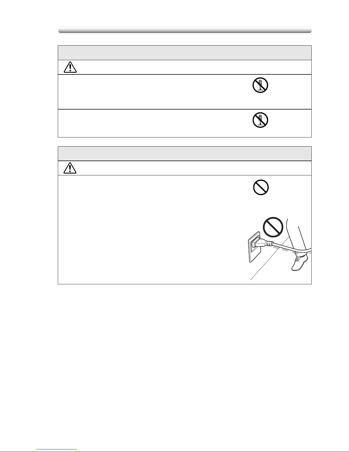
Disassemble and modification
WARNING
• Do not attempt to remove the covers and panels which
have been fixed to the product. Some products have a
high-voltage part or a laser beam source inside that
could cause an electrical shock or blindness.
• Do not modify this product, as a fire, electrical shock, or
breakdown could result. If the product employs a laser,
the laser beam source could cause blindness.
Power cord
WARNING
• Do not scratch, abrade, place a heavy object on, heat,
twist, bend, pull on, or damage the power cord. Use of a
damaged power cord (exposed core wire, broken wire,
etc.) could result in a fire or breakdown.
Should any of these conditions be found, immediately
turn OFF the power switch, unplug the power cord from
the power outlet, and then call your authorized service
representative.
Page 20

Safety Information
1-20
Power source
WARNING
• Use only the specified power source voltage. Failure to
do that could result in a fire or electrical shock.
• Connect power plug directly into wall outlet having the
same configuration as the plug. Use of an adapter leads
to the product connecting to inadequate power supply
(voltage, current capacity, grounding), and may result in
fire or shock. If proper wall outlet is not available, the
customer shall ask qualified electrician for the
installation.
• Do not use a multiple outlet adapter nor an extension
cord in principle. Use of an adapter or an extension cord
could cause a fire or electrical shock.
Contact your authorized service representative if an
extension cord is required.
• Consult your authorized service representative before
connecting other equipment on the same wall outlet.
Overload could result in a fire.
CAUTION
• The outlet must be near the equipment and easily
accessible. Otherwise you can not pull out the power
plug when an emergency occurs.
Power plug
WARNING
• Do not unplug and plug in the power cord with a wet
hand, as an electrical shock could result.
• Plug the power cord all the way into the power outlet.
Failure to do this could result in a fire or electrical shock.
CAUTION
• Do not tug the power cord when unplugging. Pulling on
the power cord could damage the cord, resulting in a fire
or electrical shock.
• Remove the power plug from the outlet more than one
time a year and clean the area between the plug
terminals. Dust that accumulates between the plug
terminals may cause a fire.
Page 21
1-21
Safety Information
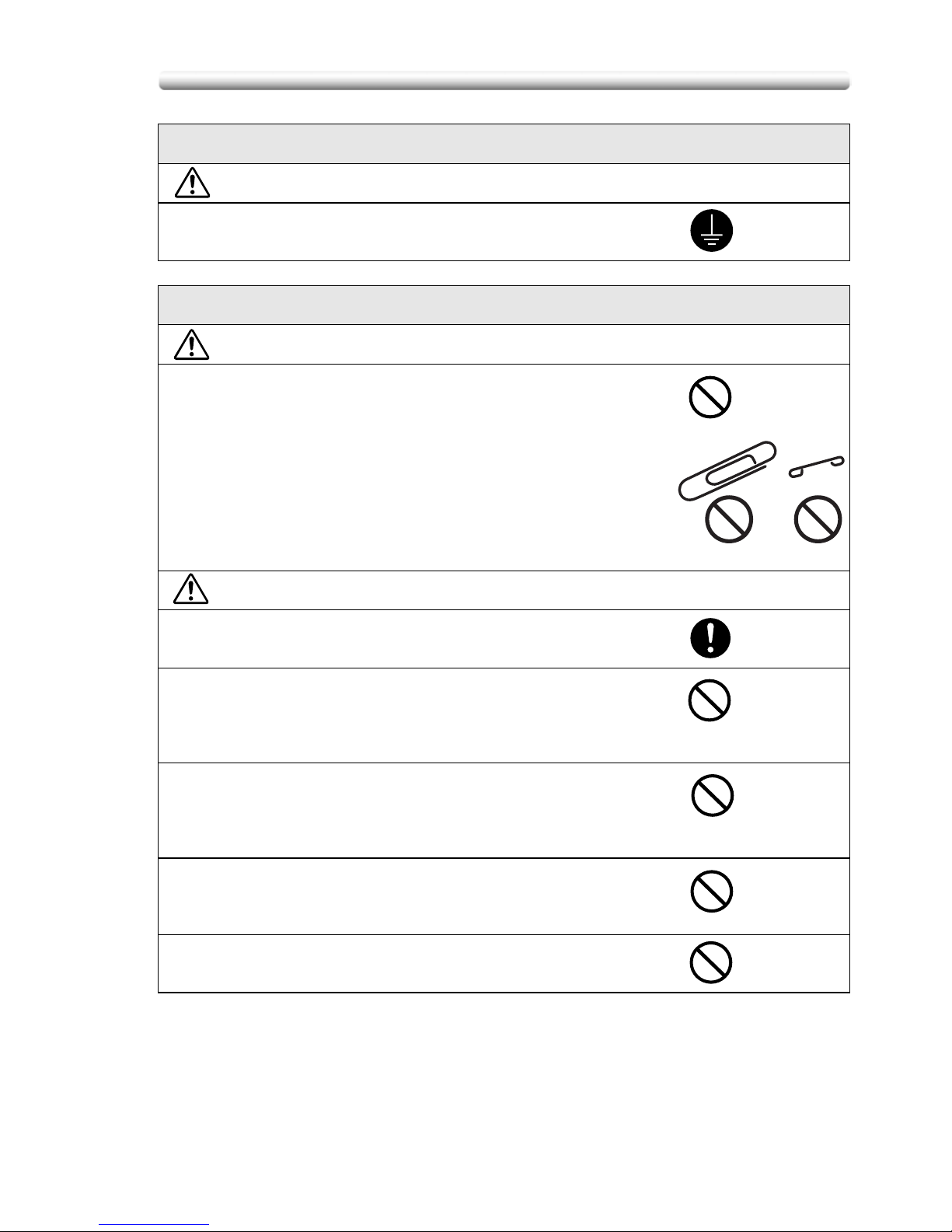
Grounding
WARNING
• Connect the power cord to an electrical outlet that is
equipped with a grounding terminal.
Installation
WARNING
• Do not place a flower vase or other container that
contains water, or metal clips or other small metallic
objects on this product. Spilled water or metallic objects
dropped inside the product could result in a fire, electrical
shock, or breakdown.
Should a piece of metal, water, or any other similar
foreign matter get inside the product, immediately turn
OFF the power switch, unplug the power cord from the
power outlet, and then call your authorized service
representative.
CAUTION
• After installing this product, mount it on a secure base. If
the unit moves or falls, it may cause personal injury.
• Do not place the product in a dusty place, or a site
exposed to soot or steam, near a kitchen table, bath, or a
humidifier. A fire, electrical shock, or breakdown could
result.
• Do not place this product on an unstable or tilted bench,
or in a location subject to a lot of vibration and shock. It
could drop or fall, causing personal injury or mechanical
breakdown.
• Do not let any object plug the ventilation holes of this
product. Heat could accumulate inside the product,
resulting in a fire or malfunction.
• Do not use flammable sprays, liquids, or gases near this
product, as a fire could result.
Page 22
Safety Information
1-22
Ventilation
CAUTION
• Always use this product in a well ventilated location.
Operating the product in a poorly ventilated room for an
extended period of time could injure your health.
Ventilate the room at regular intervals.
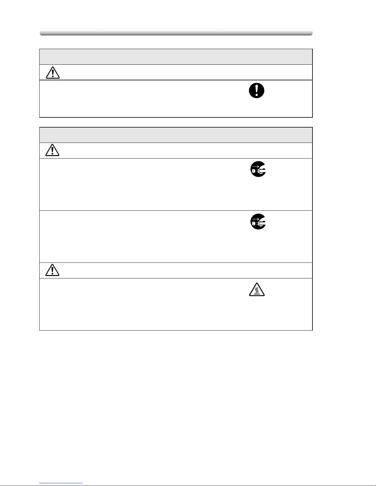
Actions in response to troubles
WARNING
• Do not keep using this product, if this product becomes
inordinately hot or emits smoke, or unusual odor or
noise. Immediately turn OFF the power switch, unplug
the power cord from the power outlet, and then call your
authorized service representative. If you keep on using it
as is, a fire or electrical shock could result.
• Do not keep using this product, if this product has been
dropped or its cover damaged. Immediately turn OFF the
power switch, unplug the power cord from the power
outlet, and then call your authorized service
representative. If you keep on using it as is, a fire or
electrical shock could result.
CAUTION
• The inside of this product has areas subject to high
temperature, which may cause burns.
When checking the inside of the unit for malfunctions
such as a paper misfeed, do not touch the locations
(around the fusing unit, etc.) which are indicated by a
“Caution HOT” caution label.
Page 23
1-23
Safety Information
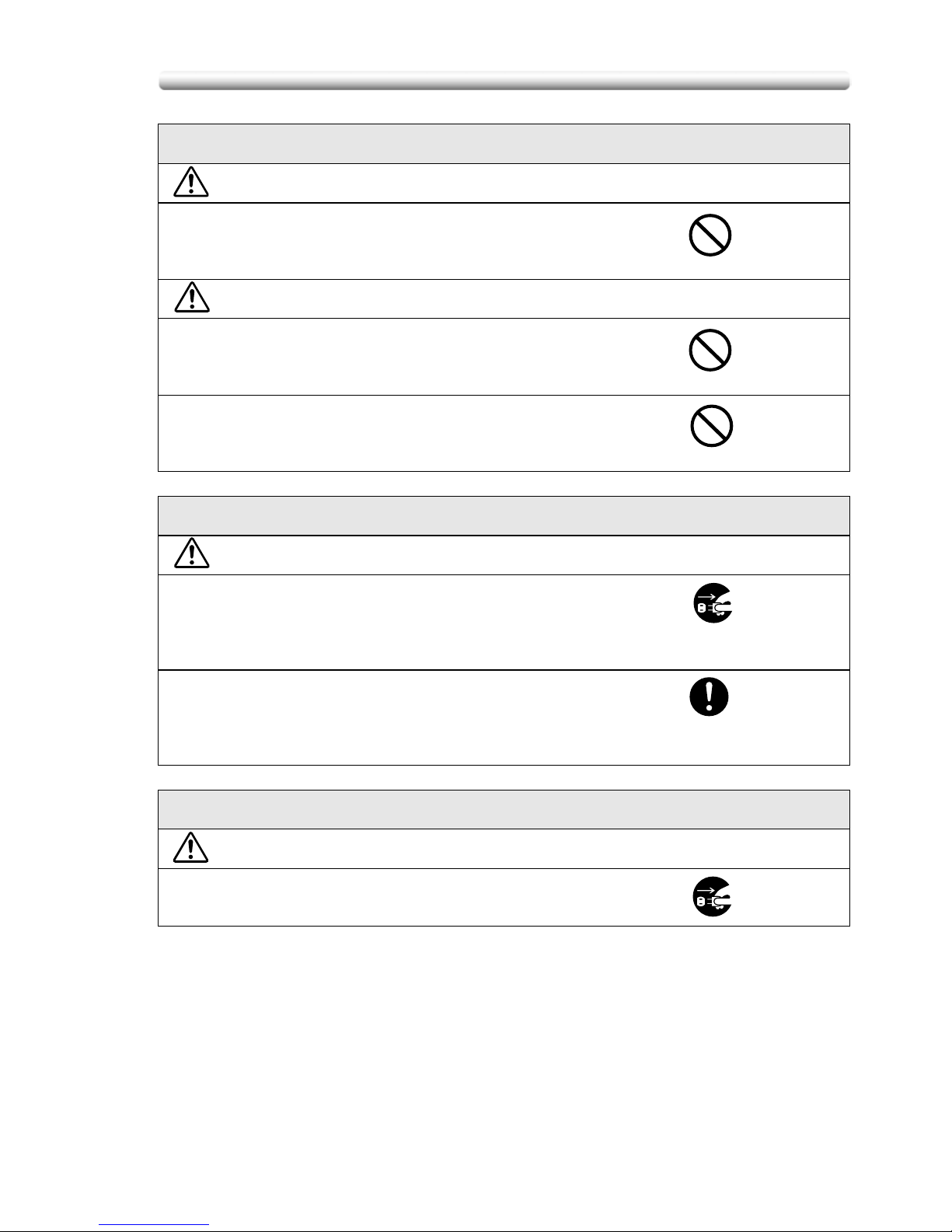
Consumables
WARNING
• Do not throw the toner bottle or toner into an open flame.
The hot toner may scatter and cause burns or other
damage.
CAUTION
• Do not leave a toner bottle or drum in a place within easy
reach of children. Licking or ingesting any of these things
could injure your health.
• Do not store toner units and PC drum units near a floppy
disk or watch that are susceptible to magnetism. They
could cause these products to malfunction.
When moving the machine
CAUTION
• Whenever moving this product, be sure to disconnect the
power cord and other cables. Failure to do this could
damage the cord or cable, resulting in a fire, electrical
shock, or breakdown.
• When moving this product, always hold it by the
locations specified in the User manual or other
documents. If the unit falls it may cause severe personal
injury. The product may also be damaged or malfunction.
Before successive holidays
CAUTION
• Unplug the product when you will not use the product for
long periods of time.
Page 24

Regulation Notices
1-24
Regulation Notices
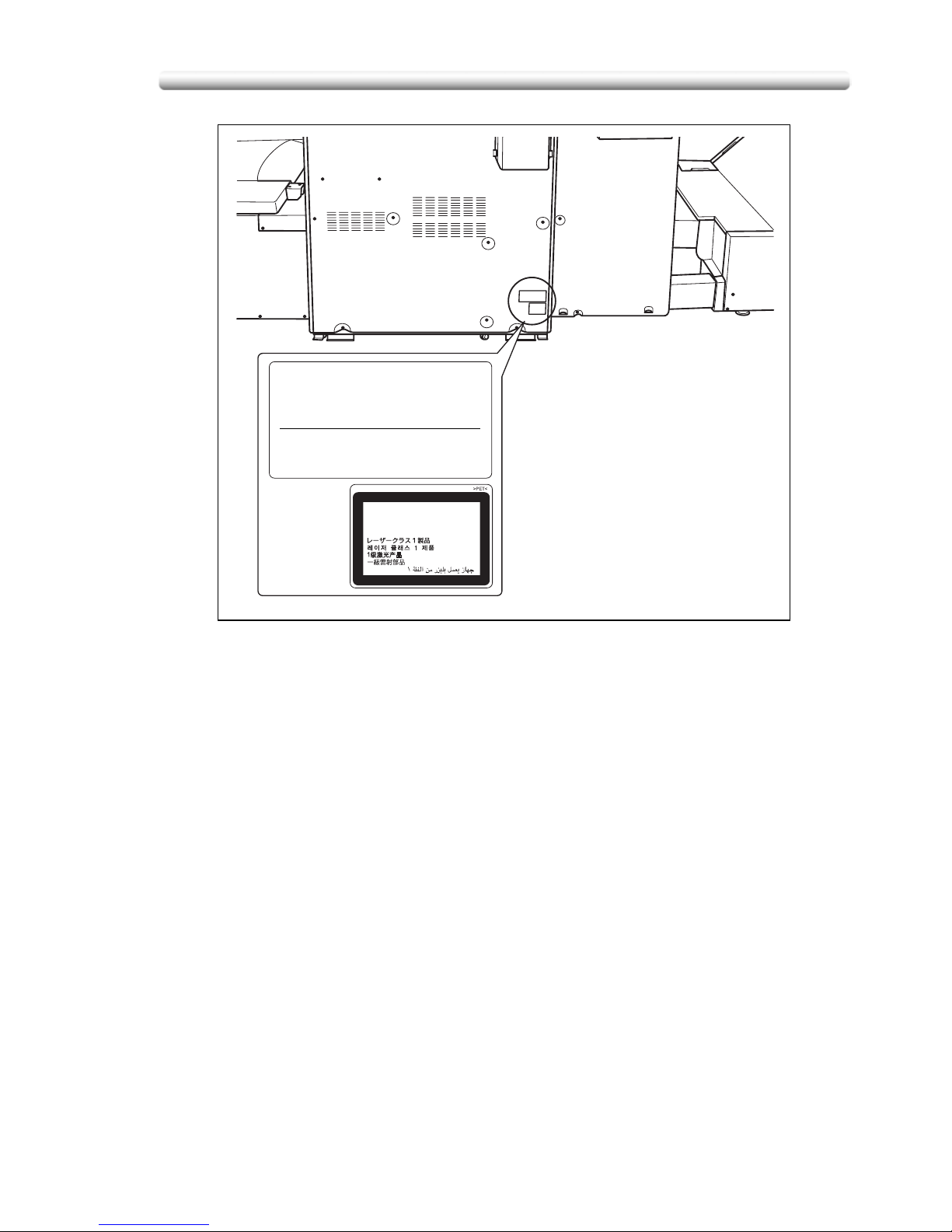
- Laser Safety
This product employs a Class 3B laser diode having maximum power of 7 mW and
wavelength of 650 nm.
This product is certified as a Class 1 laser product. Since the laser beam is
concealed by protective housings, the product does not emit hazardous laser
radiation as long as the product is operated according to the instructions in this
manual.
- For Denmark Users
ADVARSEL
Usynlig laserstråling ved åbning, når sikkerhedsafbrydere er ude af funktion.
Undgå udsættelse for sråling.
Klasse 1 laser produkt der opfylder IEC 60825-1 sikkerheds kravene.
Dansk: Dette er en halvlederlaser. Laserdiodens højeste styrke er 7 mW og
bølgelængden er 650 nm.
- For Norway Users
ADVARSEL
Dersom apparatet brukes på annen måte enn spesifisert I denne bruksanvisning,
kan brukeren utsettes for usynlig laserstråling som overskrider grensen for laser
klass 1.
Dette en halvleder laser. Maksimal effekt till laserdiode er 7 mW og bøkgelengde er
650 nm.
- For Finland, Sweden Users
LUOKAN 1 LASERLAITE
KLASS 1 LASER APPARAT
VAROITUS!
Laitteen käyttäminen muulla kuin tässä käyttöohjeessa mainitulla tavalla saattaa
altistaa käyttäjän turvallisuusluokan 1 ylittävälle näkymättömälle lasersäteilylle.
Tämä on puolijohdelaser. Laserdiodin suurin teho on 7 mW ja aallonpituus on 650
nm.
VARNING!
Om apparaten används på annat sätt än I denna bruksanvisning specificerats, kan
användaren utsättas för osynlig laserstrålning, som överskrider gränsen för
laserklass 1.
Det här är en halvledarlaser. Den maximala effekten för laserdioden är 7 mW och
våglängden är 650 nm.
Page 25
1-25
Regulation Notices
- Ozone Release
During print operation, a small quantity of ozone is released. This amount is not
large enough to harm anyone adversely. However, be sure the room where the
machine is being used has adequate ventilation, especially if you are printing a high
volume of materials, or if the machine is being used continuously over a long period.
- Electromagnetic Interference
This product must be used with a shielded network cable and shielded USB
interface cable.
The use of non-shield cables is likely to result in interference with radio
communications and is prohibited under CISPR 22 and local rules.
- For European Users
This product complies with the following EU directives:
89/336/EEC, 73/23/EEC and 93/68/EEC
This declaration is valid for the areas of the European Union (EU) or EFTA only.
This device must be used with a shielded network cable and shielded USB interface
cable. The use of non-shielded cables is likely to result in interference with radio
communications and is prohibited under 89/336/EEC rules.
- For German Users
Maschinenlarminformations -Verordnung - 3. GSGV, 18.01.1991:
Der arbeitsplatzbezogene Immisionswert betraegt 70 dB(A) oder weniger nach ISO
7779.
CLASS 1 LASER PRODUCT
APPAREIL A RAYONNEMENT
LASER DE CLASSE 1
LASER KLASSE 1 PRODUKT
KONICA MINOLTA BUSINESS TECHNOLOGIES, INC.
1-6-1, Marunouchi, Chiyoda-ku, Tokyo, Japan
MANUFACTURED: KHK
THIS PRODUCT COMPLIES WITH 21 CFR
CHAPTER I, SUBCHAPTER J
Page 26
Caution Labels and Indicators
1-26
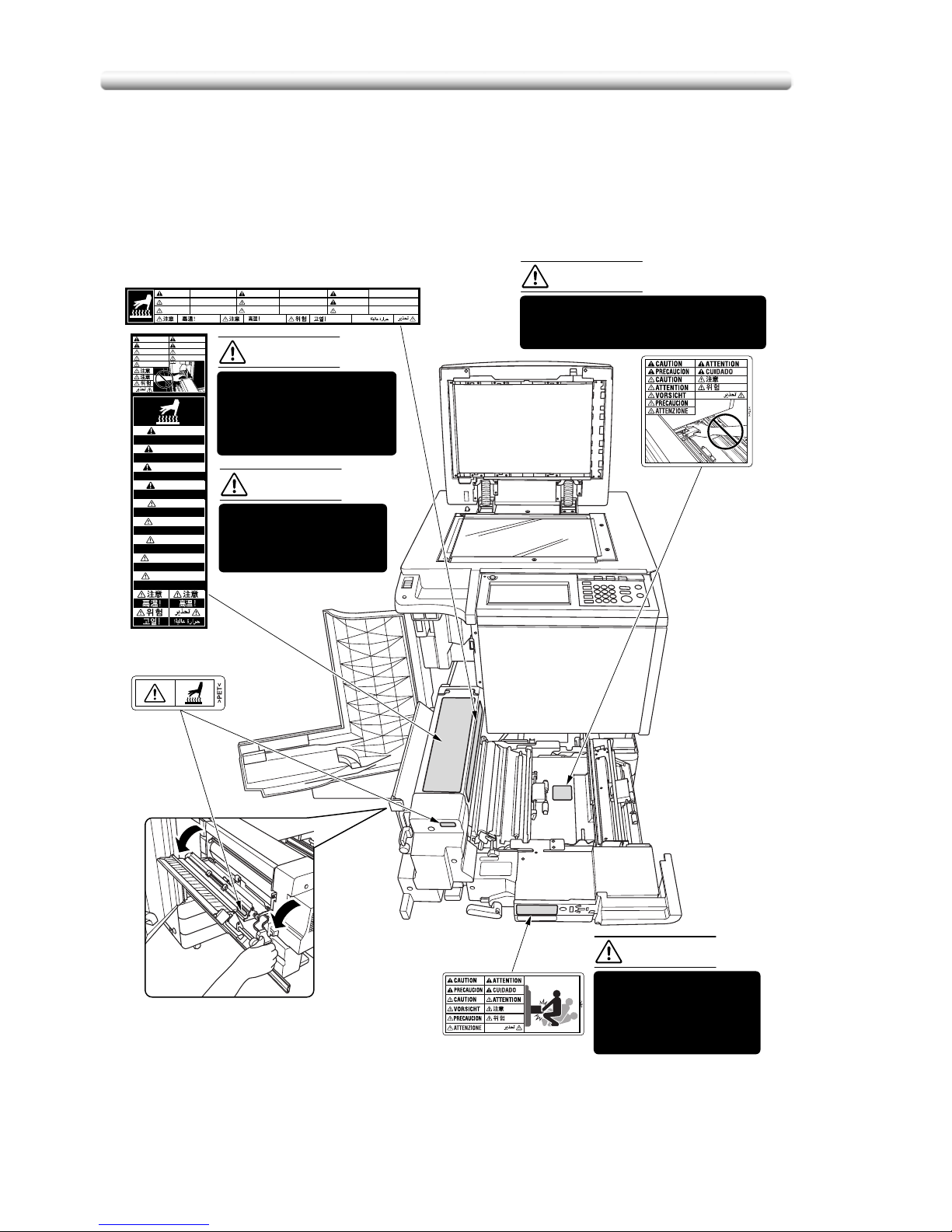
Caution Labels and Indicators
The caution labels and indicators are attached to the machine areas, as shown
below, where you are advised to pay special attention to avoid any dangerous
situations or serious injury.
High temperature!
CAUTION
Température élevée!
ATTENTION
¡Temperatura alta!
¡Temperatura alta!
PRECAUCION
Heisse Oberfläche!
Alta temperatura!
ATTENZIONE
PRECAUCION
VORSICHT
High temperature!
Température élevée!
Alta temperatura!
CUIDADO
ATTENTION
CAUTION
High temperature!
High temperature!
CAUTION
Température élevée!
Température élevée!
ATTENTION
¡Temperatura alta!
¡Temperatura alta!
PRECAUCION
Alta temperatura!
CUIDADO
CAUTION
ATTENTION
PRECAUCION
CUIDADO
Heisse Oberfläche!
Alta temperatura!
ATTENZIONE
PRECAUCION
VORSICHT
ATTENTION
CAUTION
ATTENZIONE
ATTENTION
CAUTION
VORSICHT
PRECAUCION
The fixing unit is very
hot.
To avoid getting burned
DO NOT TOUCH.
DO NOT put your hand
between the main body
and developing fixing unit;
otherwise you may be
injured.
The conveyance fixing
unit is heavy.
Use care and draw it out
gently; otherwise you
may be injured.
DO NOT put your hand between the
main body and developing fixing
unit; otherwise you may be injured.
(Right side of the fixing unit)
(Top surface of
the fixing unit)
(Inside of the fixing unit)
CAUTION
CAUTION
CAUTION
CAUTION
Page 27
1-27
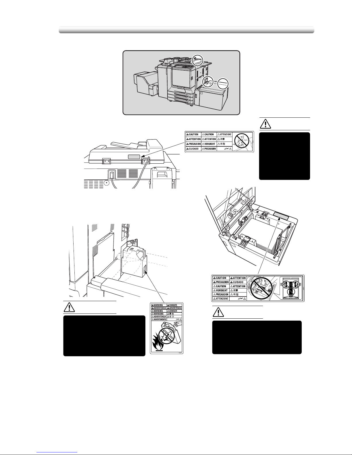
Caution Labels and Indicators
DO NOT throw the toner
recovery box into a fire. If it
is thrown into a fire, the
toner may ignite and cause
a dangerous situation.
To avoid any unexpected
injury, DO NOT put your hand
into the holes (3 places) on
the bottom plate of the LCT.
DO NOT INSERT
your finger into
the two RADF
hinge portions;
otherwise you
may be injured.
(Rear side of the RADF)
(Inside of the LCT)
(Right rear side
of the Main body)
CAUTION
WARNING
CAUTION
Page 28
Caution Labels and Indicators
1-28
CAUTION
ATTENTION
PRECAUCION
CUIDADO
CAUTION
ATTENTION
VORSICHT
PRECAUCION
ATTENZIONE
注意
CAUTION
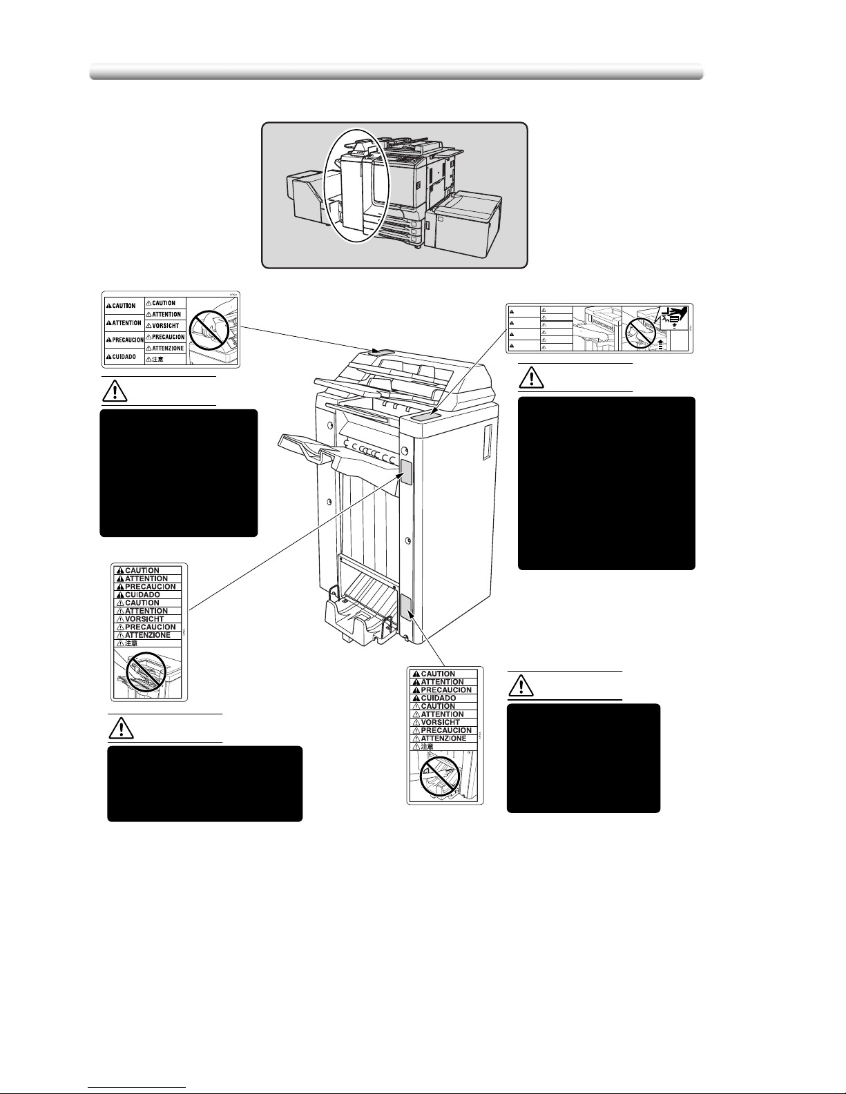
CAUTION
CAUTION
Inside the lower paper
exit outlet is the roller
drive unit. DO NOT put
your hand into it;
otherwise you may be
injured.
Use care after opening the
paper exit outlet. DO NOT put
your hand into it; otherwise
you may be injured.
(Finisher with PI-110
Cover Sheet Feeder only)
To avoid injury, DO NOT
put your hand on top of
the printed sheets.
Be sure to hold both sides
of the printed sheets when
removing them, and DO
NOT leave your hand on
the printed sheets while
the primary (main) tray
goes up.
DO NOT insert your
finger into the bottom
of the upper part of the
feeder when returning
to its original position;
otherwise you may be
injured.
CAUTION
Page 29
1-29
Installation Space
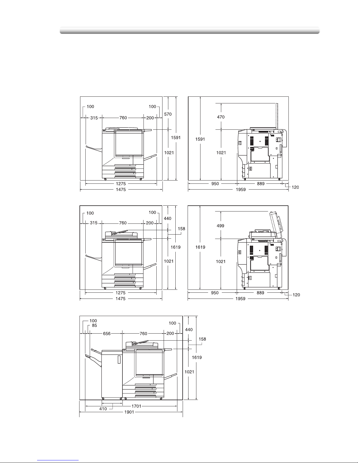
Installation Space
Allow sufficient space for facilitating copy operation, changing parts, and periodic
inspection. Leave an adequate space behind the machine to let hot air out from the
rear fan.
Unit: mm
CS520 + CV-131 (Front) CS520 + CV-131 (Right side)
CS520 + DF-319 (Front) CS520 + DF-319 (Right side)
CS520 + DF-319 + FS-513 (Front)
Page 30
Installation Space
1-30
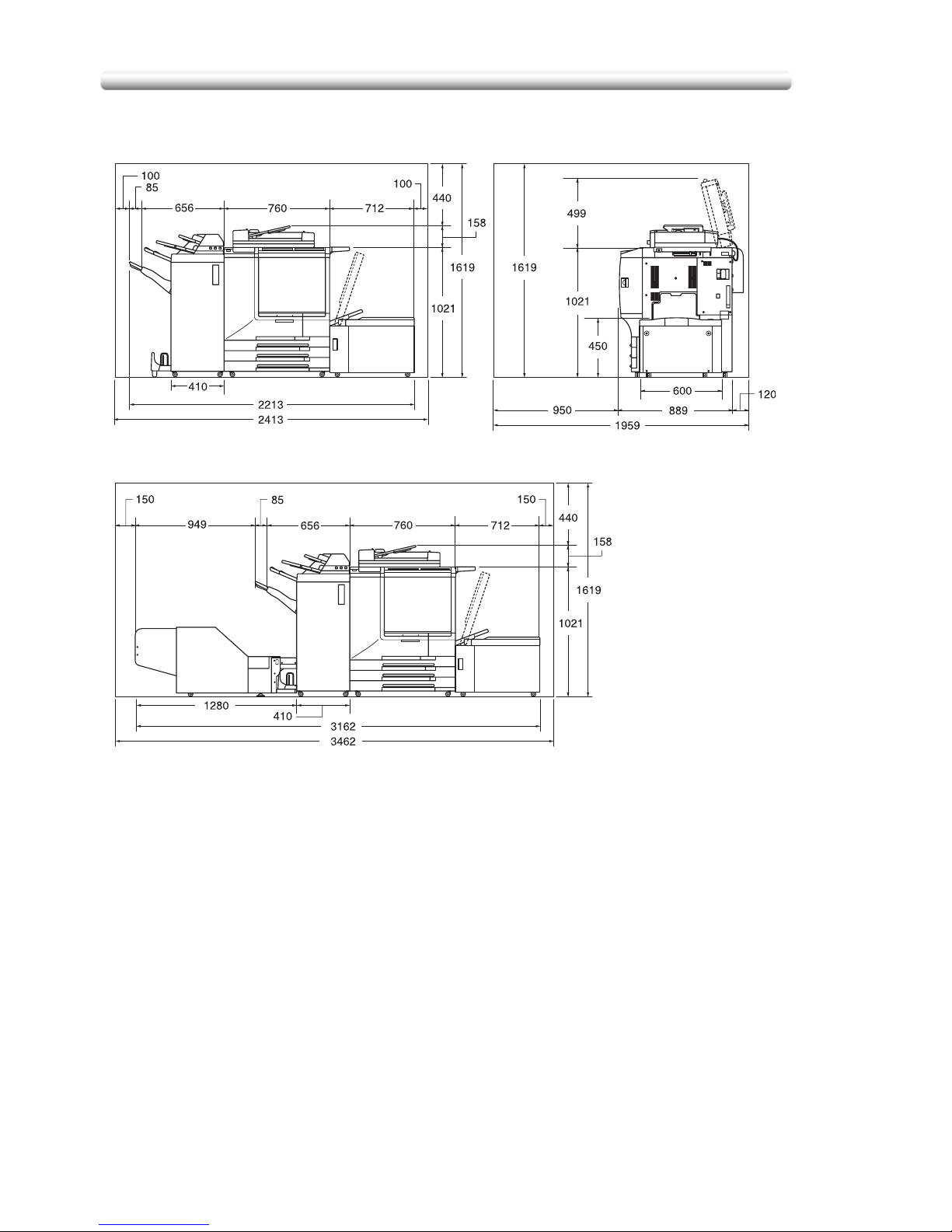
Finisher primary (main) tray of FS-513/FS-606 Finisher gradually goes down while printed
materials output. DO NOT allow any object to interfere with the operation of the tray on
the left side of the finisher, as any interference may cause damage to the finisher.
Unit: mm
CS520 + DF-319 + FS-606
+ PI-110 + LT-211 (Front) (Right Side)
CS520 + DF-319 +LT-211
CS520 + DF-319 + FS-606 + PI-110 + LT-211
+ TU-109A Kit + TU-109 (Front)
Page 31

1-31
Installation Space
End of life
[1]
The symbol "the crossed-out wheeled bin" indicates that at end-of-life of the
equipment separate collection is required in the EU Member States. The black bar
specifies that the appliance is put on the market after 13 August 2005. Reference:
Directive 2002/96/EC.
Page 32

Installation Space
1-32
Page 33

2
Machine Information
Machine Configuration, Turning
On the Power and Loading Paper
Machine Configuration....................................................................... 2-34
Turning On the Power Switch ............................................................2-48
Loading Paper....................................................................................2-55
Page 34

Machine Configuration
2-34
Machine Configuration
External Machine Items
Page 35

2-35
Machine Configuration
1 RADF (Reversing Automatic Document Feeder) (option) automatically
feeds multiple originals one at a time to the platen glass for copying.
2 Platen cover (option) covers documents to be copied and holds them in
place.
3 Work table provides a convenient workspace for documents both before
and after copying.
4 Key counter (option) manages the number of copies made on the machine.
5 Toner access door opens to replenish the black toner or colour toner.
6 Toner recovery box door opens to replace the filled toner recovery box
with new one.
7 Multi-sheet bypass tray opens to use copy paper of the other size or type
than those loaded in the main body trays or LCT.
8 Tray 4 (LT-211 Large Capacity Tray) (option) holds 2,500 sheets (90 g/m
2
paper) from 13”x19” to B5.
9 Right side door opens to allow removal of mishandled paper.
10 Tray 3 (universal tray) is user-adjustable and holds 500 sheets (90 g/m
2
paper) from 13”x19” to A5R.
11 Tray 2 (universal tray) is user-adjustable and holds 500 sheets (90 g/m
2
paper) from 13”x19” to A5R.
12 Tray 1 (universal tray) is user-adjustable and holds 500 sheets (90 g/m
2
paper) from 13”x19” to A5R.
13 Front door opens to allow removal of mishandled paper.
14 FS-513 Finisher (option) sorts, staple-sorts, or groups copies into finished
sets.
15 FS-606 Finisher (option) sorts, staple-sorts, or groups copies into finished
sets. FS-606 also folds or staples & folds copies into booklet-styled sets, or
folds max. 3 copies in three.
16 TU-109A kit (option) connects the finisher and trimmer unit.
17 TU-109 Trimmer unit (option) trims the end of booklet.
18 PI-110 Cover sheet feeder (option) loads cover sheet paper and feeds the
sheet as cover to the sorted sets, used in combination with FS-513/FS-606
Finisher.
19 Power switch turns copier power On/Off when pressed.
20 LCD Touch screen displays interactive operation screens.
21 Control panel controls copier operations and displays messages as
required.
Page 36

Machine Configuration
2-36
Internal Machine Items
1 Lever A can be moved to withdraw the conveyance fixing unit for removal
of mishandled paper.
2 Fixing unit fuses the toner onto the copy paper.
3 Main power switch used only by service representative turns machine
power on/off when pressed.
4 Total counter indicates the total number of prints made.
5 Black print counter indicates the total number of the black prints made.
Page 37

2-37
Machine Configuration
Standard/Optional Equipment
PK-507/PK-508 Punching kit
PI-110 Cover sheet feeder
CV-131 Platen cover
DF-319 Document feeder
Work table
Key counter
LT-211 Large
CS520
FS-513 Finisher
MU-412 Memory unit
HD-106 Hard disk drive
IP-901Printer controller
FS-606 Finisher
TU-109A kit
TU-109 Trimmer unit
capacity tray
(Fiery S300 50C-K)
main body
Page 38

Machine Configuration
2-38
Control Panel Layout
1 CONTRAST ADJUSTMENT DIAL can be turned to adjust the touch panel
contrast.
2 LCD TOUCH SCREEN displays machine and copying status, help
information, interactive screens, and touch keys for selecting all functions.
3 CHECK displays a screen showing all settings that are selected for the
current job.
4HELP displays a screen with help for the currently selected function, or to
access the Key Operator Mode Screen.
5KEYPAD enters numeric values.
6PRINTER switches the machine operation mode to printer. This key
functions only when internal print controller is installed.
7 SCANNER switches the machine operation mode to scanner.
8COPY switches the machine operation mode to copy.
9TIMER lights when the timer function is set.
10 INTERRUPT stops copying in progress to allow copying from the platen
glass.
11 POWER SAVER ON/OFF activates power-saving mode for times when the
copier is inactive, or activates Timer Interrupt mode when Weekly Timer
function is active.
12 STOP stops the copying sequence; deletes the stored memory.
13 PROOF COPY outputs a single set of copies to confirm whether the current
settings are selected properly.
14 START activates copying or scanning.
15 [C] (CLEAR QTY.) allows resetting of print quantity.
12 45671110983
121319 18 14151617
Page 39

2-39
Machine Configuration
The touch screen of the control panel is covered with glass. Do not
drop heavy objects on the glass or put excess weight or pressure on
it, otherwise the glass may be scratched or break to cause injury.
When the Call for Service Screen (p. 5-148) is displayed, be sure to
contact your service representative immediately.
The control panel of this machine can be slightly lowered to three angled
positions to ensure easy access by anyone, regardless of the physical or
positional status of the operator. Your authorized service representative can
make this setting for you.
16 [P] (COUNTER) displays the Counter Screen or accesses programming
modes for setting special functions.
17 AUTO RESET restores copier to automatic mode settings or to Key
Operator settings.
18 JOB MEMORY displays screens for selecting job store/job recall functions.
19 ACCESS sets the machine to allow copying only when the EKC password
is entered.
Page 40

Machine Configuration
2-40
Basic Screen
1 Folder keys:
FREE JOB is selected to specify a copy job conditions.
When scanning starts, FREE JOB changes to SCAN JOB, then changes to
PRINT JOB when the machine starts printing.
FREE JOB at the right side of SCAN JOB or PRINT JOB can be touched to
specify a reserve job conditions. Up to 9 reserve jobs can be set. The arrow
keys at the right side of folder keys are used to scroll.
2 Word icons:
ADD TONER icon is displayed when toner supply becomes low. The toner
colour to be supplied is indicated by a letter; C (cyan), M (magenta), Y
(yellow), or K (black).
Printer icon indicates the machine status when operating as a printer.
3 Graphic icons:
Original direction icon indicates the original direction specified on the
Special Original popup menu.
Image adjust icon indicates the enhance mode specified on the Special
Original popup menu.
Rotation icon is displayed when Rotation automatically functions.
Toner recovery box icon is displayed when replacement of the toner
recovery box is due.
PM icon is displayed when preventive maintenance is due.
4 Message area displays the machine status and procedure required at that
time.
5 Reserve job counts the reserve jobs already specified.
Page 41

2-41
Machine Configuration
6 Original count counts the original pages placed in the document feeder as
they are scanned.
7 TYPE/SIZE key appears when the Bypass key is selected, and is touched
to specify the type and size of the paper loaded in the Multi-sheet bypass
tray.
8 Count/Set indicator indicates the print quantity entered from the control
panel keypad, and also indicates the print count on the left of the set count
while printing.
9 Memory indicator indicates the remaining memory available for the next
operation.
10 STATUS key is touched to view the current job status, to change the
printing order of reserve jobs, or to cancel printing a reserve job.
11 IMAGE ADJUST key is touched to display five sorts of the Image
Adjustment Setting Screens to adjust the image quality.
12 SPECIAL ORIGINAL key is touched to specify the condition of originals to
be scanned.
13 APPLICATION key is touched to select various application functions.
14 ROTATION OFF key is touched to release the Rotation function.
15 STORE key is touched to store scanned images into memory.
16 Lens mode area is used to select the desired magnification ratio.
17 Paper size area is used to select the desired paper size or APS.
18 Copy mode area is used to select the copy mode (1)1, 1)2, 2)1, or
2)2).
19 Colour mode area is used to specify the desired colour mode (single
colour, black, full colour, or auto).
20 Output mode keys are used to specify the desired output mode.
21 Output icon area displays the appropriate output icon according to the
selected output mode.
Page 42

Machine Configuration
2-42
FS-513/FS-606 Finisher (with PK-507/PK-508 Punching Kit)
1 Finisher door opens to the internal Finisher to allow clearing mishandled
paper, replenishing staples, and emptying waste basket of Punching kit.
2 Booklet tray (FS-606 Finisher only) holds sets output in Fold mode,
Stapling & Fold mode, or Three-fold mode.
3 Primary (Main) tray holds sets output in Non-sort mode, Sort mode
(offset), Staple-sort mode, or Group mode (offset).
4 Secondary (Sub) tray holds sets output in Sort mode or Group mode with
face down/up mode.
FS-513 Finisher FS-606 Finisher
Page 43

2-43
Machine Configuration
1 Entrance lever opens downward to remove mishandled paper.
2 PK-507/PK-508 Punching kit (option) punches file holes in the output
copies.
3 Cover sheet conveyance lever opens to remove mishandled paper.
4 Sub tray conveyance lever opens to remove mishandled paper.
5 Stacker conveyance lever opens to remove mishandled paper.
6 Lower lever opens to remove mishandled paper.
7 Stacker unit knob can be turned to ease removal of mishandled paper
from the Stacker unit.
8 Stacker unit folds or stitches & folds copies into booklet-styled sets, and
also folds max. 3 copies in three.
9 Waste basket (option) holds waste paper punched out.
10 Stacker unit handle withdraws unit to allow removal of mishandled paper
and replacement of staple cartridge.
11 Cartridge housing holds staple cartridge to be replaced when supplying
staples.
FS-513 Finisher
FS-606 Finisher with
PK-507/PK-508 Punching kit
Page 44

Machine Configuration
2-44
PI-110 Cover Sheet Feeder
1 Cover sheet feeder control panel controls cover sheet feeder operations.
2 Upper unit release lever can be moved to slide the upper unit of cover
sheet feeder for removal of mishandled paper.
3 Upper tray guide plates hold cover sheets to fix the position.
4 Upper tray holds cover sheets for use in cover sheet output mode.
5 Lower tray holds cover sheets for use in cover sheet output mode or a
copied set in manual stapling/punching/three-fold mode.
6 Lower tray guide plates hold cover sheets to fix the position.
Page 45

2-45
Machine Configuration
LT-211 Large Capacity Tray
1 LCT lever can be moved downward to ease removal of mishandled paper.
2 LCT top door opens to allow paper loading or removal of mishandled
paper.
3 LCT left side door opens to allow removal of mishandled paper.
4 Paper loading button is pressed to lower the bottom plate to allow loading
paper.
5 Paper feed roller conveys the copy paper to the main body.
6 LCT paper guides hold copy paper to fix the position.
7 LCT paper guide knobs can be turned to move or fix the LCT paper guide.
8 Rear stopper fixes the rear end of copy paper.
9 Rear stopper knobs can be turned to move or fix the rear stopper.
10 LCT bottom plate goes up automatically when paper supply becomes low,
and goes down when the paper loading button is pressed.
Page 46

Machine Configuration
2-46
TU-109 Trimmer Unit
DO NOT place heavy objects on the trimmer stacker or apply any weight on
it, and DO NOT use it for storage.
Excessive weight applied to the inside or outside of the trimmer stacker will
damage the equipment.
1 Front-right cover opens to allow removal of mishandled paper.
2 Front door opens to allow removal of mishandled paper or waste paper.
3 Trimmer stacker holds sets output in Trimming mode.
4 Trimmer unit tray slides to the left side each time a trimmed booklet is
delivered.
5 Trimmer stacker cover opens to allow you to take out the finished sets.
6 TU-109A kit connects the Finisher and Trimmer unit.
7 FS-606 Finisher allows the Trimmer unit to be installed.
Page 47

2-47
Machine Configuration
1 Trimmer unit knob can be turned to ease removal of mishandled paper.
2 Waste basket holds waste paper cut off from the booklets.
3 Trimmer pressure release lever opens to allow removal of mishandled
paper.
Page 48

Turning On the Power Switch
2-48
Turning On the Power Switch
To Tu r n On the P o w e r
1. Turn ON the power switch.
The power switch is located on the left side of the control panel.
The main power switch is located on the upper-left side of the internal main
body. Be sure not to use the main power switch in usual operation.
2. The Wake-up Screen and Warm-up Screens will be displayed.
Page 49

2-49
Turning On the Power Switch
A few seconds after the Wake-up Screen appears in the LCD touch screen,
seven types of Warm-up Screens will be displayed in succession for approx.
7.0 minutes.
You can set reserve jobs while the machine is warming up. Touch the LCD
screen to change the Warm-up Screen to the Basic Screen, then check that
the message “Ready to copy reserve” is displayed on the Basic Screen. See
p. 3-78.
3. The Basic Screen will be displayed.
The message on the Basic Screen will inform you that copying job is now
available.
• When the initial settings are changed by the Key Operator, the modified
conditions will be displayed on the Basic Screen.
• When “Enter E.K.C. password” is displayed, enter your password to use
the machine.
• When “Set the key counter” is displayed, insert the key counter to its inlet
on the right side of the main body.
Page 50

Turning On the Power Switch
2-50
To Turn Off the Power
1. Turn OFF the power switch.
The power switch is located on the left side of the control panel.
The touch screen and all the LEDs on the control panel will go out.
Be sure not to use the main power switch in usual operation.
When the machine is under control of the Weekly Timer function, turning off
the power switch will deactivate the function.
Page 51

2-51
Turning On the Power Switch
Reducing the Power in Standby Mode (Auto Low Power)
This function automatically lowers the power after a specified period (initially 15
minutes) of copier inactivity. The LCD screen will go off.
The Auto Low Power function can be set to 5 minutes/ 10 minutes/ 15
minutes/ 30 minutes/ 60 minutes/ 90 minutes/ 120 minutes/ 240 minutes in
the Key Operator mode. For information about the Key Operator setting, see
p. 14-435.
To start a copying job, press any key on the control panel.
The Auto low power will be released and the LCD screen recovers usual brightness.
• If the Auto Shut-Off function activates at the same time, the power will be
turned off without the LCD screen becoming dark.
• The LCD screen will not go off during a duplex copying job or when the
Jam Position Screen is displayed.
Page 52

Turning On the Power Switch
2-52
Shutting Off Automatically (Auto Shut-Off)
This function automatically shuts off the power after a specified period (initially 90
minutes) of copier inactivity.
To start a copying job, press [
POWER SAVER ON/OFF
].
The copying operation will become available.
• The Auto shut-off can be set for 30 minutes/ 60 minutes/ 90 minutes/ 120
minutes/ 240 minutes in the Key Operator mode. For information about
the Key Operator setting, see p. 14-435.
• When “Timer interrupt mode / Enter password” is displayed after pressing
[
POWER SAVER ON/OFF
], see p. 8-212 and follow the procedure to
continue.
Page 53

2-53
Turning On the Power Switch
Shutting Off / Reducing the Power Manually
Follow the procedure below to shut off the power manually.
The machine is initially set to activate the Manual Shut-Off function. The
Manual Low Power can be selected in the Key Operator setting. See p. 14-
436.
1. Press [
POWER SAVER ON/OFF
] for one second or longer, then
release it.
If Manual Low Power is selected in the Key Operator setting, the machine
automatically activates the Low Power mode before releasing [
POWER
SAVER ON/OFF
].
2. The Shut-Off mode will be activated.
The [
POWER SAVER ON/OFF
] LED will be lit and all other LEDs and the LCD
screen will be turned off.
Be sure to press [
POWER SAVER ON/OFF
] for one second or longer,
otherwise the following message will be displayed and the Shut-Off (Low
Power) mode will not be activated.
To release the mode, press [
POWER SAVER ON/OFF
].
The machine will be available for copying operation.
Press POWER SAVER more than one second,
then release it for shut off mode
Press POWER SAVER continuously more
than one second for low power mode
Page 54

Turning On the Power Switch
2-54
Entering an EKC Password (EKC)
The Electronic Key Counter (EKC) allows the Key Operator to monitor all copying
activities by controlling EKC password accounts. Copy quantity limits for specific
accounts can be set.
The EKC is not factory-set. An EKC password is required only when the EKC is
activated, a User Password is assigned, and “Enter E.K.C. password” is displayed
on the touch screen.
Copying will be available by following procedure:
For details of the EKC setting, see p. 14-411 to p. p. 14-418.
1. Enter EKC password.
Enter your 8-digit EKC password, using the keypad.
To set an EKC password, see p. 14-413.
If an invalid EKC password is entered, continue by entering the correct
password.
2. Press [
START
].
Your current copy count and copy limit will be displayed for 3 sec.
3. Start a copying job.
When the message changes to “Ready to copy”, copying job is available on
the machine.
When your copy count reaches the copy limit, the message “Copy limit
reached” will be displayed. In that case, contact the Key Operator to reset
your copy limit.
4. Press [
ACCESS
].
The initial state will be restored, with the message “Enter E.K.C. password”
displayed on the screen.
Current count / limit
018888/025000
Page 55

2-55
Loading Paper
Loading Paper
A paper indicator is shown on each tray key of the Basic Screen to indicate the
paper level (six levels are provided: ) of the tray. (The Multi-sheet
bypass tray displays only “ ” when paper in the tray becomes empty.)
When paper supply in a tray becomes low, the indicator “ ” appears on the tray
key, and then it changes to “ ” when paper in that tray becomes empty and the
tray key blinks on the screen.
Follow the procedure below to supply the empty tray with copy paper.
Each tray key displays a paper type and a number which indicates the paper
weight to be loaded. The following paper types are provided:
Normal, Recycled, Coloured, High Q, Coated, Colour sp, Tab paper,
Exclusive A to J
The numbers corresponding to the paper weight are:
1: 64~74 g/m
2
2: 75~80 g/m
2
3: 81~105 g/m
2
4: 106~162 g/m
2
5: 163~209 g/m
2
6: 210~256 g/m2 (for LCT and Multi-sheet bypass tray only)
Key Operator can change this setting. See p. 14-420 for the main body trays
and the LCT. See p. 3-86 for the Multi-sheet bypass tray.
• Be sure to load only the paper type and weight set for the tray.
• Using paper with punch holes, copy result may not be satisfactory due to
the hole positions.
• The tray specified as Tab paper is unavailable for Staple, STITCH&FOLD,
Fold, or Three-Fold mode.
Page 56

Loading Paper
2-56
Loading Paper in Tray 1 ,2, and 3
1. Withdraw tray 1, 2, or 3, and open the paper feed roller.
Do not withdraw the tray forcibly; otherwise you may be injured.
Withdraw the tray completely until the green line appears at the left rear side
of the tray. Otherwise, the paper feed roller may not open or machine trouble
may be caused.
To load the same size as loaded before, proceed to step 4.
If changing the paper size, proceed to the next step.
2. Adjust the position of the side guide plate.
Pull up the lock lever at the front, then slide the side guide plate to the desired
position.
See the size indication on the bottom plate of the tray to determine the
position of the side guide plate.
Push down the lock lever firmly until it clicks in position in order to fix the side
guide plate.
1
2
1
22
2
3
Page 57

2-57
Loading Paper
Be sure to fix the side guide plate in position according to the size indication
on the tray bottom plate so that the machine can detect the correct paper
size.
3. Adjust the position of the rear stopper.
To slide the rear stopper to the right, hold it at the upper part and slide it while
pressing down slightly.
On the other hand, hold the rear stopper at the lower part to slide it to the left.
Be sure to press down the rear stopper when moving it to the right, and also
be sure to hold it at the lower part when moving it to the left. Do not move the
rear stopper forcibly, otherwise it may be damaged.
4. Place paper on the tray.
Load paper aligning it to the right side of the tray, then align the rear stopper to
the paper.
• Be sure that the rear guide plate is securely aligned to the paper;
otherwise machine trouble may occur.
• Do not load above the limit indicated on the side guide plate.
1
2
Page 58

Loading Paper
2-58
5. When paper is seated properly, close the paper feed roller.
6. Gently push in the tray until it locks into place.
The indicator “ ” on the tray key will change to “ ”.
Do not clam the tray into the main body; otherwise machine trouble may be
caused.
Page 59

2-59
Loading Paper
Loading Paper in Multi-Sheet Bypass Tray
When using the Multi-sheet bypass tray, specify the paper type to be loaded on the
tray at the same time. See p. 3-86 for details.
1. Open the Multi-sheet bypass tray located on the right side of the
copier.
1. Load copy paper, and adjust the paper guides to the paper size.
• Stack paper up to 250 sheets 90 g/m2. When loading special paper, do
not exceed the limit indicated on the paper guides, otherwise paper
misfeed may occur.
• Do not load paper of the weight less than 64 g/m
2
, otherwise paper
misfeed may occur.
• The transparency film or ink-jet paper is not available on this machine. Do
not load the transparency film or ink-jet paper on the Multi-sheet bypass
tray.
2. When copying is completed, close the Multi-sheet bypass tray.
Page 60

Loading Paper
2-60
Loading Paper in LCT (LT-211)
Be sure to load only the paper type and weight set for the LCT. Key Operator
can change this setting. See p. 14-420.
1. Open the LCT top door.
The LCT bottom plate will go up.
Without the power turned on, the LCT bottom plate will not function. Be sure
to turn on the power switch before loading paper in the LCT.
To load the same size as loaded before, proceed to step 3.
If changing the paper size, proceed to the next step.
2. Adjust the position of the LCT paper guides and rear stopper.
(1) Turn the four LCT paper guide knobs and two rear stopper knobs
counterclockwise to loosen them.
Page 61

2-61
Loading Paper
(2) Move the upper part of the two LCT paper guides to the appropriate
positions according to the size indication, then turn the LCT paper guide
knobs (two for each) clockwise to fix the guides.
(3) Move the position of the rear stopper to the appropriate positions
according to the size indication on the bottom plate, then turn the two
rear stopper knobs clockwise to fix the rear stopper.
3. Press the paper loading button once, then load the paper into the
LCT.
The LCT bottom plate will go down.
Page 62

Loading Paper
2-62
4. Repeat the step
3
until the bottom plate will not go down any
more.
• Do not load above the limit indicated on the LCT paper guides.
• Be sure that the rear stopper is correctly positioned according to the
paper size to be loaded; otherwise machine trouble may occur.
5. Close the LCT top door.
Page 63

2-63
Loading Paper
Loading Tabbed Sheets in Tray 1, 2, or 3
When TAB is displayed on the tray key of the Basic Screen, follow the procedure
below to supply the tray with tabbed sheets.
The tray paper type can be specified in the Key Operator setting. For details,
see p. 14-420.
The tab extension width must be 12.5 mm or less.
1. Withdraw tray 1, 2, or 3.
2. Open the paper feed roller.
3. Place the tabbed sheets on the tray as illustrated above.
4. Move the green levers (located at the front and the left side) to the
edge of the paper.
5. Close the paper feed roller, then push in the tray until it locks into
place.
Rear
Front
Printed
side
2nd TAB
3rd TAB
ONE FINISHED SET
Rear
Front
Printed
side
1st TAB
2nd TAB
3rd TAB
1st TAB
2nd TABS
3rd TABS
1st TABS
Example: 3 Tabbed sheets loaded in position for one finished set.
Example: 9 Tabbed sheets loaded in position for 3 finished sets.
THREE FINISHED SETS
Page 64

Loading Paper
2-64
Loading Tabbed Sheets in LCT (LT-211)
• The tab extension width must be 12.5 mm or less.
• To load the tabbed sheets into LCT, contact your service representative to
position the rear stopper for the paper size to be loaded.
1. Open the LCT top door.
2. Press the paper loading button to lower the LCT bottom plate.
3. Load the tabbed sheets into the LCT as illustrated above.
4. Close the LCT top door.
Example: 3 Tabbed sheets loaded in position for one finished set.
Example: 9 Tabbed sheets loaded in position for 3 finished sets.
ONE FINISHED SET
THREE FINISHED SETS
1st TAB
2nd TAB
3rd TAB
1st TAB
2nd TAB
3rd TAB
1st TAB
2nd TAB
3rd TAB
3rd TAB
2nd TAB
1st TAB
Rear
Rear
Front
Front
Printed
side
Printed
side
Page 65

2-65
Loading Paper
Loading Tabbed Sheets in Multi-Sheet Bypass Tray
The tab extension width must be 12.5 mm or less.
1. Open the Multi-sheet bypass tray located on the right side of the
copier.
2. Load tabbed sheets as illustrated above.
3. Adjust the paper guides to the paper size.
4. Specify the paper type as TAB for the Multi-sheet bypass tray.
See p. 3-86 for specifying the paper type of the Multi-sheet bypass tray.
Example: 3 Tabbed sheets loaded in position for one finished set.
Example: 9 Tabbed sheets loaded in position for 3 finished sets.
Printed
side
Printed
side
1st TAB
2nd TAB
3rd TAB
1st TAB
2nd TAB
3rd TAB
1st TAB
2nd TAB
3rd TAB
1st TAB
2nd TAB
3rd TAB
ONE FINISHED SET
THREE FINISHED SETS
Rear
Rear
Front
Page 66

Loading Paper
2-66
Page 67

3
Copying Operations
How to Make a Basic Copy
Selecting Colour Mode ......................................................................3-68
Positioning Originals ..........................................................................3-70
Setting Print Quantity.........................................................................3-76
Setting Job During Warm-up .............................................................3-78
To Stop Scanning/Printing ................................................................. 3-81
Selecting Paper Size ..........................................................................3-82
Copying Using Special Paper (Multi-Sheet Bypass Tray)..................3-86
Selecting Magnification Ratio (Lens Mode) .......................................3-91
Making Double-Sided Copies (1)2, 2)2) ......................................... 3-94
Making Single-Sided Copies from Double-Sided Originals (2)1)...3-102
To Scan Originals into Memory (Store Mode) ..................................3-104
To Set Next Copying Job (Reserve) .................................................3-106
To Check/Control Jobs in Progress (Job Status Screen).................3-109
Output Mode for Machine without Finisher .....................................3-112
Output Mode for Machine with Finisher ..........................................3-116
Selecting Binding Mode...................................................................3-125
Page 68

Selecting Colour Mode
3-68
Selecting Colour Mode
The following four colour modes are available:
AUTO mode detects whether the scanned original is coloured or black-and-white
image, and automatically selects either FULL COLOUR mode or BLACK mode for
copying.
FULL COLOUR mode makes full-coloured copies whether the original image is
coloured or not.
BLACK mode makes black-and-white copies whether the original image is coloured
or not.
SINGLE COLOUR mode copies in one colour to be selected from red, green, blue,
magenta, cyan, or yellow.
The FULL COLOUR mode is initially selected. Follow the procedure below to
change the Colour mode.
Specification for Colour Mode
/ A colour mode is incompatible with another colour mode.
/ Incompatible with AUTO: Tab Paper, Fold/Stitch&Fold/Trimming (with Booklet
selected), Combination, Booklet, Overlay, Overlay Memory
/ Incompatible with FULL COLOUR: Tab Paper
/ Incompatible with SINGLE COLOUR: Tab Paper
The colour adjustment function is provided on this machine. See Section
7: "Colour Image Adjustment".
Some adjustments cannot be made in the BLACK mode and SINGLE
COLOUR mode.
Incompatible with BLACK: Hue/Saturation/Brightness in Colour Adjust,
Colour Balance, Any function except Auto in Screen, Colour/Text of Image
Judge in Others, Original Type in Special Original
Incompatible with SINGLE COLOUR: Hue/Saturation/Brightness in Colour
Adjust, Colour Balance, Colour/Text of Image Judge in Others, Original Type
in Special Original
1. Touch a mode key under the COLOUR MODE on the Basic Screen
to select the desired Colour mode.
Page 69

3-69
Selecting Colour Mode
When starting a new copying job, be sure to close the RADF securely, then
press [
AUTO RESET
].
FULL COLOUR
is already highlighted when the initial settings are restored.
The initial settings may have been altered by Key Operator. See p. 14-409 for
details.
Selecting
SINGLE COLOUR
will display the popup menu to specify a colour.
Touch the desired colour key, then touch
OK
.
The selected colour will be indicated under the COLOUR MODE indication of
the Basic Screen, with the
SINGLE COLOUR
key highlighted.
Touch
CANCEL
to restore the previous setting.
2. Select additional copy conditions, as desired.
If the colour adjustment is desired, see Section 7: "Colour Image
Adjustment".
3. Enter the desired print quantity from the control panel keypad.
See p. 3-76 for details on setting print quantity.
4. Position original(s).
See p. 3-70 for details on positioning originals.
5. Press [
START
].
Page 70

Positioning Originals
3-70
Positioning Originals
Set the originals in the RADF or on the platen glass to copy.
Positioning Originals in RADF
The document feeder (RADF) automatically feeds up to 100 originals directly to the
platen area, starting with the top sheet. The RADF should only be used for
unstapled, smooth, flat originals.
See p. 12-371 for details of the original sizes available in the RADF.
Positioning originals in Normal mode
1. Arrange originals in order.
2. Position original(s) FACE UP in the document feeder tray.
Place two-sided originals with page one FACE UP.
The direction of the originals should conform to the Original direction icon
displayed at the upper left corner of the Basic Screen.
Up to 100 originals can be set at a time.
• The copy result may not be satisfactory if the originals are set in wrong
direction. Be sure that the originals are set in the same direction as
indicated by the Original direction icon, especially when making doublesided copies or using Staple, Stitch&Fold, Fold, or Booklet mode. See
p. 9-242 for details.
• Be sure not to use unsuitable RADF originals. See p. 12-370 for details.
• Do not set more than 100 originals or over the limit indicated on the paper
guides; otherwise a paper misfeed will occur to cause damage to the
originals.
Page 71

3-71
Positioning Originals
Before placing originals in the tray, be sure the document feeder is closed
fully. Once closed, do not open the document feeder, otherwise the selected
copy conditions may be altered automatically.
3. Adjust paper guides.
Positioning originals in Mixed original mode
Mixed size originals can be copied together from the document feeder.
• To use the Mixed original mode, see procedure on p. 9-249.
• See p. 12-371 for available combinations of mixed originals.
1. Arrange originals in order.
Arrange the mixed size originals as illustrated below.
Setting
direction
To the
depth
To the left
Page 72

Positioning Originals
3-72
2. Position mixed originals FACE UP, aligned with the left rear side of
the document feeder tray.
Place two-sided originals with page one FACE UP.
Up to 100 originals can be set at a time.
• Be sure not to use unsuitable RADF originals. See p. 12-370 for details.
• Do not set more than 100 originals or over the limit indicated on the paper
guides; otherwise a paper misfeed will occur to cause damage to the
originals.
Before placing originals in the tray, be sure the document feeder is closed
fully. Once closed, do not open the document feeder, otherwise the selected
copy conditions may be altered automatically.
3. Adjust paper guides.
Page 73

3-73
Positioning Originals
Positioning originals in Z-Folded original mode
Z-Folded original mode detects the folded original size without using the size
detection sensor of the RADF.
• To use the Z-Folded original mode, see procedure on p. 9-252.
• See p. 12-371 for available sizes of folded originals.
1. Arrange originals in order.
2. Position original(s) FACE UP in the document feeder tray.
Place two-sided originals with page one FACE UP.
Up to 100 originals can be set at a time.
• Be sure not to use unsuitable RADF originals. See p. 12-370 for details.
• Do not set more than 100 originals or over the limit indicated on the paper
guides; otherwise a paper misfeed will occur to cause damage to the
originals.
Before placing originals in the tray, be sure the document feeder is closed
fully. Once closed, do not open the document feeder, otherwise the selected
copy conditions may be altered automatically.
3. Adjust paper guides.
Page 74

Positioning Originals
3-74
Positioning Original on Platen Glass
Use the platen glass when originals are not suitable for use with the document
feeder, e.g., when size is incompatible, or when originals are folded, stapled, torn, or
in generally poor condition.
1. Raise the document feeder or platen cover.
2. Place original FACE DOWN in the left rear corner.
The direction of the original should conform to the Original direction icon
displayed at the upper left corner of the Basic Screen.
The copy result may not be satisfactory if the original is set in wrong
direction. Be sure that the original is set in the same direction as indicated by
the Original direction icon, especially when making double-sided copies or
using Staple, Stitch&Fold, Fold, or Booklet mode. See p. 9-242 for details.
3. Gently close the document feeder or platen cover to prevent the
original from shifting on the glass.
Page 75

3-75
Positioning Originals
When selecting Dual Page, Non-Image Area Erase, AUTO mode in Repeat, or
AUTO Layout, DO NOT CLOSE the document feeder. For details on each
function, see Section 11: "Applications".
Do not place too heavy originals, or do not press strongly when thick
original is placed and is under pressure of RADF; otherwise the
glass may be broken and you may be injured.
Page 76

Setting Print Quantity
3-76
Setting Print Quantity
This section describes how to set or change print quantity.
To Set Print Quantity
The copier is initially set to copy the original set in amounts determined by the print
quantity setting, then outputs sorted sets.
1. Enter the desired print quantity from the control panel keypad.
Entered quantity will be displayed on the touch panel.
Page 77

3-77
Setting Print Quantity
To Change Print Quantity
Follow the procedure below to change the print quantity that has been already
entered.
1. Press [
C (CLEAR QTY.
)].
The quantity displayed on the touch panel will return to 1.
2. Enter the correct quantity.
Entered quantity will be displayed on the touch panel.
Page 78

Setting Job During Warm-up
3-78
Setting Job During Warm-up
While the copier is warming up after power is turned on, select copy conditions and
start scanning so that the copier may start printing immediately when the copier
engine is ready.
1. Turn on the power switch of the machine.
Seven types of Warm-up Screens display in succession.
See p. 2-48 for details on turning on the power switch.
2. Touch the LCD panel to change the Warm-up Screen to the Basic
Screen.
Check that the message “Ready to copy reserve” is displayed on the Basic
Screen.
3. Set the desired copying conditions, and enter the print quantity.
See p. 3-76 for details on setting print quantity.
Page 79

3-79
Setting Job During Warm-up
4. Position original(s) FACE UP in the RADF or FACE DOWN on the
platen glass.
See p. 3-70 for details on positioning originals.
5. Press [
START
].
The original for the job will be scanned, and the highlighted
FREE JOB
folder
key will change to
SCAN JOB
.
When scanning is completed,
SCAN JOB
will change to
RESERVE JOB
, and
the next
FREE JOB
becomes active.
6. If setting more than one reserve job, touch the next
FREE JOB
to
highlight it.
Page 80

Setting Job During Warm-up
3-80
7. Set the desired copying conditions, enter the print quantity,
position original(s), then press [
START
].
Up to 9 reserve jobs can be prepared.
Copying on the reserve job will start automatically after completing the warmup.
• The Job Status Screen allows you to alter the output order of the reserve
jobs or to delete the reserve job. See p. 3-109.
• If all three reserve job keys are used, touch the active
FREE JOB
key at
the far right to scroll. See p. 3-106.
To stop printing, press [
STOP
]. See p. 3-81 for details.
Page 81

3-81
To Stop Scanning/Printing
To Stop Scanning/Printing
Follow the procedure below to stop scanning or printing.
1. Touch to highlight
SCAN JOB
or
PRINT JOB
to be suspended.
2. Press [
STOP
].
The current machine operation of the selected job will be suspended.
If wrong job is suspended, touch
CONTINUE
on the popup menu
immediately, select the correct job, then press [
STOP
] to suspend it.
3. Touch
EXIT
to cancel the job.
All the data of the selected job will be deleted.
To restart the suspended job, touch
CONTINUE
on the popup menu.
Page 82

Selecting Paper Size
3-82
Selecting Paper Size
To select an appropriate paper size for getting your desired copy result, use APS
(Automatic Paper Selection), or select paper size manually on the touch screen, as
required.
To Select Paper Size Automatically (APS)
APS detects the size of originals placed on the RADF or platen glass and
automatically selects and feeds copy paper of the same size, or selects an
appropriate size according to the magnification ratio selected.
APS is not available when using non-standard size or wide size paper.
1. Touch to highlight
APS
under the PAPER SIZE on the Basic
Screen.
2. Select additional copy conditions, as desired.
3. Enter the desired print quantity from the control panel keypad.
See p. 3-76 for details on setting print quantity.
4. Position original(s).
• See p. 12-370 for the original sizes detectable from the RADF or on the
platen glass.
• Detectable original sizes can be changed from AB sizes to inch sizes, only
A sizes, or AB sizes and inch sizes mixed. See p. 14-436.
• See p. 3-70 for details on positioning originals.
• Key Operator can deactivate APS when the original is set in the RADF or
on the platen glass. See p. 14-436.
5. Press [
START
].
Scanned image will be printed on the paper size automatically selected.
Page 83

3-83
Selecting Paper Size
• If the appropriate copy paper is not loaded in any tray, no copying will be
performed, and a message will prompt you to load the appropriate paper.
• Copy result may not be satisfactory due to the Rotation function. In this
case, turn the function OFF manually. See. p. 8-214.
• See the table below for the relation of original size, magnification ratio and
copy paper size.
Paper size Paper size
Original size
Magnification
Magnification
Page 84

Selecting Paper Size
3-84
To Specify Desired Paper Size (AMS)
When a paper size is specified on the touch screen, an appropriate reduction or
enlargement ratio will be selected automatically according to the original size
detected from the RADF or the platen glass.
Wide paper size can be specified when AMS is in use.
In this case, the same magnification ratio as that of the standard size will be
selected automatically.
1. Touch a tray key on the Basic Screen to select the desired paper
size.
Selected tray key will be highlighted, and under the LENS MODE the
AMS
key
will also be highlighted.
If copying in 1.000 (100%) magnification mode and specifying a paper size,
see p. 3-91.
2. Select additional copy conditions, as desired.
3. Enter the desired print quantity from the control panel keypad.
See p. 3-76 for details on setting print quantity.
4. Position original(s).
• See p. 12-370 for the original sizes detectable from the RADF or on the
platen glass.
• See p. 3-70 for details on positioning originals.
5. Press [
START
].
Scanned image will be printed on the specified paper size in the magnification
ratio automatically selected.
Page 85

3-85
Selecting Paper Size
• Copy result may not be satisfactory due to the Rotation function. In this
case, turn the function OFF manually. See. p. 8-214.
• See the table below for the relation of original size, copy paper size, and
magnification ratio automatically selected.
Paper size
Original size
Page 86

Copying Using Special Paper (Multi-Sheet Bypass Tray)
3-86
Copying Using Special Paper
(Multi-Sheet Bypass Tray)
Use the Multi-sheet bypass tray to copy using special (non-standard) paper.
Select the special paper type and weight from the selections previously specified by
the Key Operator, then select the size to be loaded on the Multi-sheet bypass tray,
as described below.
Transparency cannot be used on this machine. DO NOT load the
transparencies into the Multi-sheet bypass tray.
• 8.5”x11”R and B6R sizes (unavailable in Tray 1 to 4) can be used in the
Multi-sheet bypass tray. Also, 210~256 g/m
2
paper can be used in the
Multi-sheet bypass tray.
• To specify the combinations of special paper type and weight to be
selected for the Multi-sheet bypass tray, see p. 14-422.
• To specify the special paper type, weight and size in Tray 1 to 4 to be used
on a regular basis, see p. 14-420.
1. Open the Multi-sheet bypass tray, and load the copy paper.
See p. 2-59 for further details of loading procedure.
For the specifications of paper in the Multi-sheet bypass tray, see p. 12-362.
2. Touch the Multi-sheet bypass tray key in the PAPER SIZE area of
the Basic Screen to highlight it.
The
TYPE/SIZE
key will appear under the bypass tray key,
APS
will be
deselected, and
AMS
will be highlighted on the Basic Screen.
3. Touch
TYPE/SIZE
.
The Paper Type/Size popup menu will be displayed.
Page 87

3-87
Copying Using Special Paper (Multi-Sheet Bypass Tray)
4. Select the paper type and weight.
To select the paper type and weight:
Select the desired one out of the six keys on the menu to highlight it.
• If the desired paper type and weight cannot be found on the popup menu,
specify it in the Key Operator mode. See p. 14-422 for details.
• When selecting Tab Paper as the special paper type to copy onto the
tabbed paper including the tab part, specify the original paper type as Tab
Paper on the Special Original popup menu. See p. 9-244.
If no paper type and weight indication is needed, touch the highlighted key to
clear the selection of the six keys.
The selected paper type and number indicating the paper weight will appear
on the bypass tray key of the Basic Screen.
5. Specify the paper size.
When using a standard size, touch STD size to highlight it.
When using a special size, specify the paper size as follows.
Page 88

Copying Using Special Paper (Multi-Sheet Bypass Tray)
3-88
To select the STD size (special):
To uc h
STD size (special)
to display the popup menu, then use arrow keys to
scroll to the desired size.
To select the Non STD size:
To uc h
Non STD size
to display the popup menu, touch the vertical or
horizontal size key to highlight it, then use the keypad on the popup menu to
enter the vertical/horizontal size, or use arrows to scroll to that number.
Page 89

3-89
Copying Using Special Paper (Multi-Sheet Bypass Tray)
To select the Wide size paper:
Tou ch
Wide size paper
to display the popup menu, use arrow keys to scroll to
the desired wide size, then touch
Lead edge
or
Rear edge
to select the paper
dimensions corresponding to the wide paper sizes entered.
Tou ch
Input size
to display the Input Size popup menu, touch the vertical or
horizontal size key to highlight it, then use the keypad on the popup menu to
enter the vertical/horizontal size, or use arrow keys to scroll to that number.
The entered number should fall within the range from the vertical/horizontal
size of the standard size corresponding to the selected wide size, to a
maximum of 330 mm/487 mm.
When selecting Wide size paper, be sure to specify the actual size of the wide
size paper to be loaded. Wide paper size information is not initially input in
this machine.
6. Touch
OK
.
The Basic Screen will be restored. The bypass tray key shows the specified
size, paper type and the number indicating paper weight, and is highlighted
along with the
TYPE/SIZE
key.
When the STD size (special) or Wide size paper is selected, the size specified
on the popup menu will be indicated on the bypass tray key.
When Non STD size is selected, the SPECIAL indication will appear instead.
Page 90

Copying Using Special Paper (Multi-Sheet Bypass Tray)
3-90
7. Select additional copy conditions, as desired.
8. Enter the desired print quantity from the control panel keypad.
See p. 3-76 for details on setting print quantity.
9. Position original(s) FACE UP in the document feeder or FACE
DOWN on the platen glass.
• See p. 3-70 for details on positioning originals.
• See p. 9-246 for details on positioning non-standard size or tabbed paper
originals.
10. Press [
START
].
Page 91

3-91
Selecting Magnification Ratio (Lens Mode)
Selecting Magnification Ratio (Lens Mode)
When the copier is turned ON, the magnification ratio is set to 1.000 (100%)
automatically on the Basic Screen.
Follow each procedure described in this section to select the desired magnification
ratio.
To Copy in 1.000 Magnification Mode
Follow this procedure to make a 100% copy of the original image.
1. Close the RADF securely, then press [
AUTO RESET
].
The initial settings are restored. Check that
APS
is highlighted to indicate that
the 1.000 magnification is selected.
The initial settings may be altered by the Key Operator. See p. 14-409.
2. Select additional copy conditions, as desired.
Specifying paper size will release 1.000 magnification and set AMS
automatically. In this case, touch
1:1
to highlight it again.
3. Enter the desired print quantity from the control panel keypad.
See p. 3-76 for details on setting print quantity.
4. Position original(s).
See p. 3-70 for details on positioning originals.
5. Press [
START
].
Page 92

Selecting Magnification Ratio (Lens Mode)
3-92
To Change Magnification Ratio
(Fixed Magnification / Zoom Mode)
Use the 8 preset ratios (0.500, 0.707, 0.816, 0.866, 1.154, 1.224, 1.414, 2.000) and
3 user preset ratios to increase or decrease magnification in fixed amounts, or use
the Zoom mode to reduce or enlarge the copied original image in 0.1% (0.001)
increments.
Specification for Fixed Magnification / Zoom Mode
/ Incompatible Conditions: AMS, Repeat mode in Repeat, Reduce & Shift in
Image Shift
See p. 8-216 for Vertical/Horizontal Zoom mode.
1. Touch
ZOOM
on the Basic Screen.
The popup menu for changing magnification ratio will be displayed.
When starting a new copying job, be sure to close the RADF securely, then
press [
AUTO RESET
].
2. Specify the desired magnification ratio.
To select a preset or user preset ratio:
Touch the desired preset or userset ratio key in the RE area to highlight it, then
touch OK.
To restore the previous setting, touch
CANCEL
.
The selected ratio will be displayed on the Basic Screen.
Page 93

3-93
Selecting Magnification Ratio (Lens Mode)
To specify a zoom ratio:
Touch the Vertical/Horizontal zoom key in the ZOOM area to highlight it.
Use the keypad on the popup menu to enter the desired magnification ratio,
then touch OK.
The selected ratio will be displayed on the Basic Screen.
• The magnification ratio should be a 4-digit number. Start with 0 if the
magnification ratio is under 1.000.
If an incorrect ratio is entered, continue by entering the correct ratio.
• Use the upper arrow (+) to enlarge, or the lower arrow (,) to reduce the
ratio in 0.1% (0.001) increments.
• To restore the previous setting, touch
CANCEL
.
3. Select additional copy conditions, as desired.
4. Enter the desired print quantity from the control panel keypad.
See p. 3-76 for details on setting print quantity.
5. Position original(s).
See p. 3-70 for details on positioning originals.
6. Press [
START
].
Page 94

Making Double-Sided Copies (1)2, 2)2)
3-94
Making Double-Sided Copies (1)2, 2)2)
The Basic Screen is initially set to 1)1 copy mode to make single-sided copies
from single-sided originals.
Follow the procedure below to make double-sided copies from the originals
scanned from the document feeder or from the platen glass.
Using RADF
Select the copy mode according to the original type (single-sided or double-sided).
Specifications for Double-Sided Copying Using RADF
/ See p. 12-370 for the information on unsuitable RADF originals.
/ Incompatible Conditions: Face Up, Multi-Page Enlargement, Non-Image Area
Erase, Verti./Horiz. mode or Auto mode of Repeat, AUTO Layout, Storing
Image in Overlay Memory
1. Touch 1 )2 or 2 )2 on the Basic Screen to highlight it.
2-2 Copying
1-2 Copying
Double-sided original
Single-sided original
Duplex copy
Duplex copy
Page 95

3-95
Making Double-Sided Copies (1)2, 2)2)
When starting a new copying job, be sure to close the RADF securely, then
press [
AUTO RESET
].
2. Check and specify the original set direction and binding mode.
The Original direction icon is located at the upper left corner of the Basic
Screen.
To change the original set direction, touch
SPECIAL ORIGINAL
on the Basic
Screen to display the Special Original popup menu, then touch the desired
original direction key to highlight it.
If the originals are upside down on the reverse side and you want to make
copies of the same direction on both sides, touch
TOP BIND
.
With this feature specified, next step is not needed. Proceed to step 4.
Tou ch OK to return to the Basic Screen.
Page 96

Making Double-Sided Copies (1)2, 2)2)
3-96
3. Select the binding mode.
To uc h
OUTPUT MENU
on the Basic Screen to display the Output Mode
popup menu, then touch the desired binding mode key to highlight it.
Selecting
TOP BIND
will make copies upside down on the reverse side,
while
RIGHT&LEFT BIND
copies normally.
To uc h OK to return to the Basic Screen.
4. Select additional copy conditions, as desired.
Some incompatible conditions may automatically release the selected copy
mode. In this case, arrange the settings so that they are compatible with the
selected copy mode.
Binding mode
Copies
Page 97

3-97
Making Double-Sided Copies (1)2, 2)2)
5. Enter the desired print quantity from the control panel keypad.
See p. 3-76 for details on setting print quantity.
6. Position originals FACE UP in the document feeder according to
the original direction.
• See p. 3-70 for details on positioning originals.
• Use RADF store mode (p. 3-104) when the original count exceeds 100.
7. Press [
START
].
The machine starts to scan originals, then prints duplex copies when ready for
output.
Press [
STOP
] to suspend the scanning or printing job. See p. 3-81 for details.
When the finisher / trimmer unit / paper exit tray capacity is
exceeded due to the print quantity selected, remove the copied sets
as they exit; otherwise, mishandled paper will occur.
Page 98

Making Double-Sided Copies (1)2, 2)2)
3-98
Using Platen Glass
Use the platen glass to scan originals unsuitable for the document feeder.
Specification for Double-Sided Copying Using Platen Glass
/ Use the Platen store mode.
/ See p. 12-370 for the information on unsuitable RADF originals.
/ Incompatible Conditions: Face Up, Image Insert, Multi-Page Enlargement,
Storing Image in Overlay Memory
1. Check and specify the original set direction and binding mode.
The Original direction icon is located at the upper left corner of the Basic
Screen.
To change the original set direction, touch
SPECIAL ORIGINAL
on the Basic
Screen to display the Special Original popup menu, then touch the desired
original direction key to highlight it.
If the originals are upside down on the reverse side and you want to make
copies of the same direction on both sides, touch
TOP BIND
.
With this feature specified, next step is not needed. Proceed to step 3.
To uc h OK to return to the Basic Screen.
Page 99

3-99
Making Double-Sided Copies (1)2, 2)2)
2. Select the binding mode.
Tou ch
OUTPUT MENU
on the Basic Screen to display the Output Mode
popup menu, then touch the desired binding mode key to highlight it.
Selecting
TOP BIND
will make copies upside down on the reverse side,
while
RIGHT&LEFT BIND
copies normally.
Tou ch OK to return to the Basic Screen.
3. Position original FACE DOWN on the platen glass according to the
original direction, then close the document feeder or platen cover.
Be sure to start from the first page.
• See p. 12-370 for paper sizes detectable on the platen glass.
• See p. 3-74 for details on positioning originals.
• Use Non-Image Area Erase to prevent the black copy marks to be
produced when scanning the original with the document feeder or platen
cover open. See p. 11-320.
Binding mode
Copies
Page 100

Making Double-Sided Copies (1)2, 2)2)
3-100
4. Touch 1)2 on the Basic Screen to highlight it.
The
STORE
key will be automatically highlighted on the screen.
DO NOT press [
AUTO RESET
] at this point, otherwise the platen mode will
be released to disable the copier from scanning the original placed on the
platen glass.
5. Select additional copy conditions, as desired.
Some incompatible conditions may automatically release the selected copy
mode. In this case, arrange the settings so that they are compatible with the
selected copy mode.
6. Enter the desired print quantity from the control panel keypad.
See p. 3-76 for details on setting print quantity.
7. Press [
START
] to scan.
The front side image of the double-sided copy will be scanned into memory.
8. Replace the original on the platen glass with the back side image
original, then press [
START
].
Repeat this step until all originals are scanned.
• Memory indicator on the upper right of the Basic Screen allows you to
check the remaining memory.
• To delete the scanned data without printing, press [
STOP
]. See p. 3-81 for
details.
9. After all originals are scanned, touch
STORE
to exit the Store
mode.
STORE
will no longer be highlighted.
10. Press [
START
] to print.
All the data in memory will be output.
 Loading...