

Page 1

o
Océ CS4300 scanner series
User Manual Océ CS4300 scanner series
Océ User manual
Page 2

Océ-Technologies B.V.
© 2008, Océ-Technologies B.V. Venlo, The Netherlands.
All rights reserved. No part of this work may be reproduced, copied, adapted, or transmitted
in any form or by any means without written permission from Océ.
Océ-Technologies B.V. makes no representation or warranties with respect to the contents
hereof and specifically disclaims any implied warranties of merchantability or fitness for
any particular purpose.
Further, Océ-Technologies B.V. reserves the right to revise this publication and to make
changes from time to time in the content hereof without obligation to notify any person
of such revision or changes.
Edition: Edition 1
Page 3

Trademarks
Océ, Océ CS4300 scanner series®are registered trademarks of Océ-Technologies B.V.
Adobe®, Acrobat®, Reader®and Distiller®are registered trademarks of Adobe®Systems
Incorporated.
PostScript®3™ is a registered trademark of Adobe®Systems Incorporated.
Microsoft®, Windows®, Windows XP®, Windows Server 2003®, Windows Vista®(32)
are either registered trademarks or trademarks of Microsoft®Corporation in the United
States and / or other countries.
Products in this publication are referred to by their general trade names. In most, if not
all cases, these designations are claimed as trademarks or registered trademarks of their
respective companies.
3
Trademarks
Page 4
Notes for the reader
Introduction
This manual helps you to use the Océ CS4300 scanner series. The manual contains a
description of the product and guidelines to use and operate the Océ CS4300 scanner
series. There are also tips to increase your knowledge of the product and to help you
manage the workflow.
Definition
Attention Getters
Parts of this user manual require your special attention. These parts provide important,
additional information or are about the prevention of damage to your properties.
Note, Attention and Caution
The words Note, Attention and Caution indicate important parts.
The attention getters with the corresponding icons#
IndicatesIconWord
Additional information about the correct operation of
the product or a tip.
Note
Information to prevent damage, for example to the
product, an original or a file.
Attention
Information to prevent personal injury. Caution is
found only in manuals that describe physical products.
The Caution indication has several icons that warn
against various hazards. The icons are shown in the
table part below.
Caution
4
Notes for the reader
Page 5

Contents
Chapter 1
About this Manual......................................................................................................9
About this Manual............................................................................................10
Chapter 2
Installation.................................................................................................................11
Installation........................................................................................................12
Chapter 3
The Operator's Panel................................................................................................21
The operator's panel........................................................................................22
Overview of the Operators Panel and LED indicators...................................23
Power Control, Buttons and LED patterns.....................................................24
Media Control – Buttons and LED Patterns....................................................29
Chapter 4
Turning Power ON/OFF - Wake/Sleep Mode.........................................................33
Main Power ON/OFF........................................................................................34
The scanner’s Self Test Procedure.................................................................35
Scanner ready to scan.....................................................................................37
Wake and Sleep modes...................................................................................38
Automatic Power ON/OFF...............................................................................39
Automatic Power ON/OFF.........................................................................39
Timer Function - Scheduling ON/OFF Times...........................................40
Automatic Shut Down after Idle Time......................................................42
Chapter 5
Loading Originals into the Scanner........................................................................45
Loading originals.............................................................................................46
Automatic loading............................................................................................47
Manual loading.................................................................................................48
Unloading the original after scan...................................................................49
Fast-loading......................................................................................................50
Soft-handling....................................................................................................51
Setting the input size.......................................................................................52
Chapter 6
Scanning....................................................................................................................53
Software applications for scanning................................................................54
Running applications from the scanner panel...............................................55
Batch scanning.................................................................................................56
5
Contents
Page 6

Chapter 7
Scanning Thick Media..............................................................................................57
Scanning Thick Media.....................................................................................58
Automatic Thick Media Adjustment...............................................................59
When Scanning in Thick Media Positions......................................................61
Chapter 8
Maintenance..............................................................................................................63
About scanner maintenance...........................................................................64
Cleaning the Scan Area...................................................................................65
Camera Alignment and Calibration................................................................69
Replacing Scanner Parts..................................................................................72
Replacing scanner parts............................................................................72
Replacing the glass-plate...........................................................................73
Replacing the White-background platen..................................................77
Replacing the Scanner Lamp-Unit............................................................81
Replacing the Dust-Filters..........................................................................84
Downloading new firmware............................................................................86
Chapter 9
Océ Scanner Agent...................................................................................................89
Introduction......................................................................................................90
Installation of Océ Scanner Agent..................................................................91
Interface of Océ Scanner Agent......................................................................92
Chapter 10
Océ Scanner Maintenance.....................................................................................101
Installation of the software............................................................................102
Océ Scanner Maintenance program.............................................................103
Chapter 11
Trouble Shooting ...................................................................................................107
Trouble Shooting General.............................................................................108
Problems Related to Scanner Installation....................................................109
Problems Related to Operation of the scanner...........................................112
Problems Related to Scanning Results........................................................117
Problems Related to Océ Copy Easy............................................................119
Technical Assistance......................................................................................120
Chapter 12
Appendix A: Important safety Instructions..........................................................121
Important safety instructions........................................................................122
Chapter 13
Appendix B: Regulations........................................................................................125
Regulations.....................................................................................................126
Chapter 14
6
Contents
Page 7

Appendix.................................................................................................................129
Reader's comment sheet ..............................................................................130
Addresses of local Océ organisations .........................................................132
7
Contents
Page 8

8
Contents
Page 9

Chapter 1
About this Manual
o
Page 10

About this Manual
Introduction
This manual explains how to operate and maintain your Océ CS4300 scanner series
scanner.
The manual assumes basic knowledge of your computer and operating system and does
not repeat material from their documentation.
This user's guide covers the following models:
■
Océ CS4336 scanner
■
Océ CS4336S scanner
■
Océ CS4342S scanner
■
Océ CS4354 scanner
Note:
The above model is ENERGY STAR® compliant.
Note:
Be sure to use the CD-ROM that came with your scanner or a newer version. Out-ofdate versions of Océ Scanner Agent software may not detect your scanner model.
Note:
Windows Compatibility - Your scanner and drivers are tested and developed to support
the most current active Microsoft Windows version OS systems. Drivers and interface
support in regard to specific Windows versions will follow the Microsoft Support Life
cycle Policy. The compatibility specifications can therefore change accordingly.
The most current OS compatibility specifications and drivers will be available on Océ's
website. See www.oce.com
Chapter 1 - About this Manual10
About this Manual
Page 11

Chapter 2
Installation
o
Page 12
Installation
Introduction
Follow the steps below for a quick and easy installation of your scanner and scanner
drivers
Attention:
Do not connect the scanner to the power or the PC.
Attention:
You must install your scanner's drivers and tools before you connect the scanner or install
any scanner software applications.
Caution:
The scanner is equipped with a three-wire (pin) grounding type plug. If you cannot insert
the
#
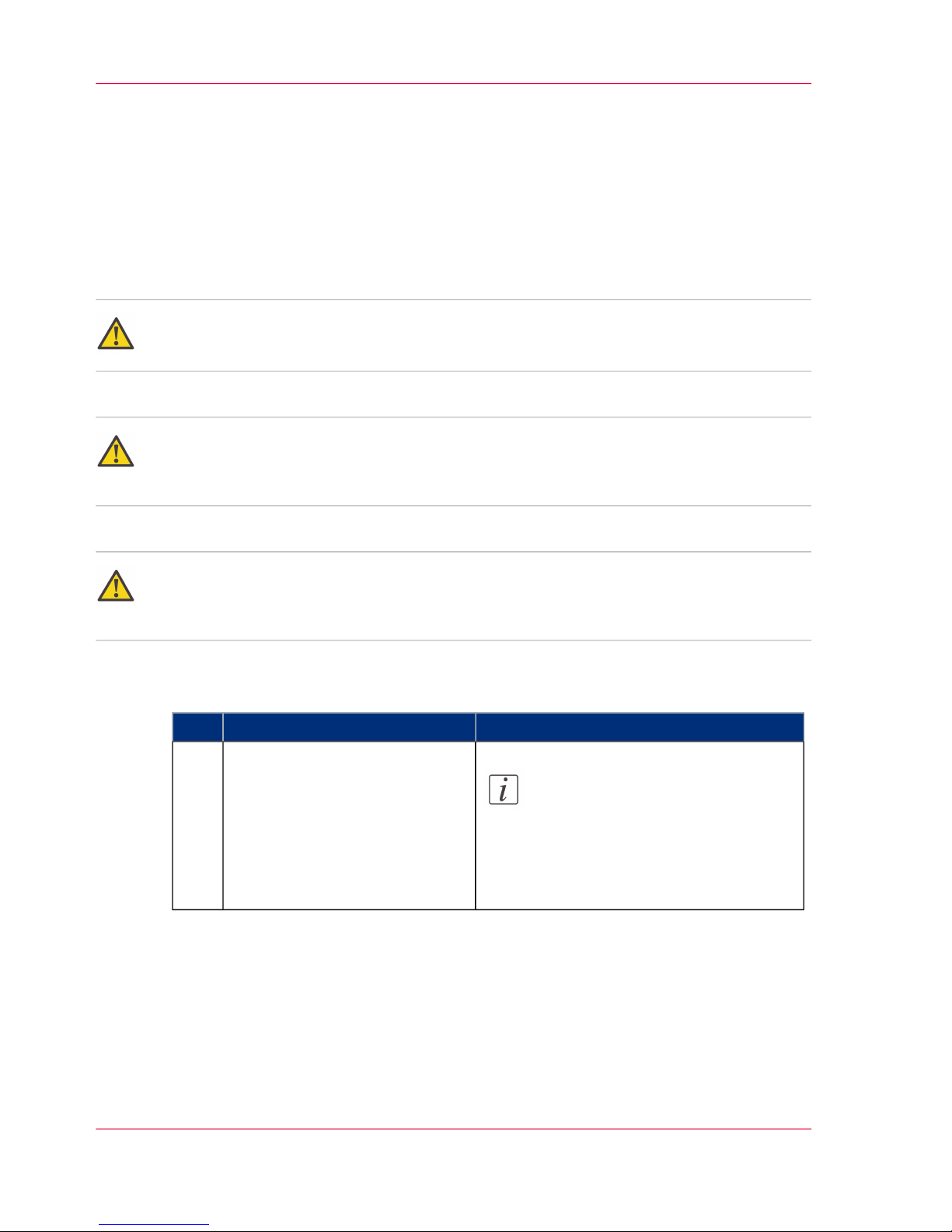
RemarksAction
Note:
: DO NOT YET CONNECT
THE SCANNER TO POWER
OR PC.
Set up the scan station.
Your scanner should be placed
either on the specially designed
stand-alone floor stand or on a
sturdy table. Make sure there is
enough space behind the scanner
to allow the media to run out.
1
Chapter 2 - Installation12
Installation
Page 13
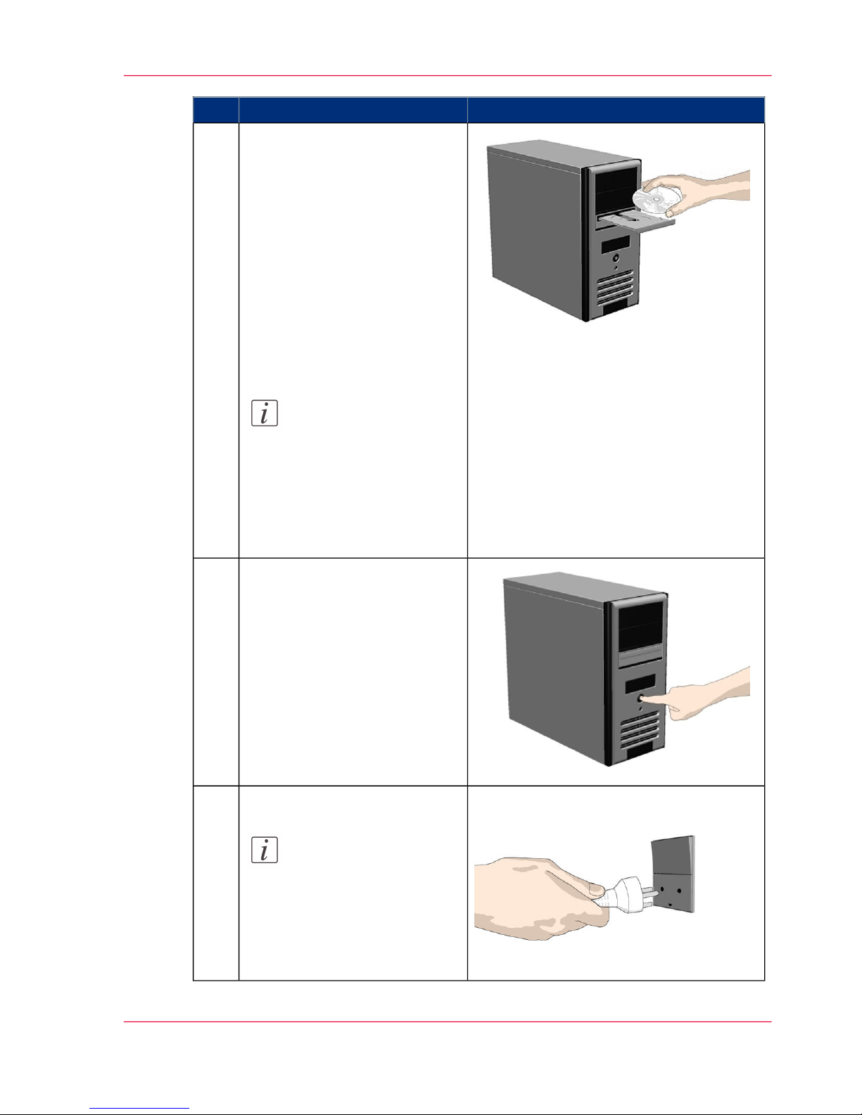
RemarksAction
Install drivers and tools on
your PC.
1.Insert the CD-ROM into your
PC. Normally the setup program
interface will start automatically.
If it does not, locate the setup.exe file on the CD and start
it manually.
2. Follow the installation wizard
to install the software.
3. Remove the CD-ROM when
installation is complete.
Note:
: You must install your
scanner's drivers and
tools before you connect
the scanner or install any
scanner software applications.
2
Shut down the PC.
Your PC must be powered off
before connection with the
scanner.
3
Disconnect the power plug.
Note:
This step is to ensure
your own personal safety
and to help protect your
device from potential
damage.
4
Chapter 2 - Installation 13
Installation
Page 14

RemarksAction
Clean the scanner feeding bed.
This is the flat surface in front
of the insertion slot. Wipe thoroughly so dirt and dust are not
dragged into the scan area with
the original.
5
Chapter 2 - Installation14
Installation
Page 15
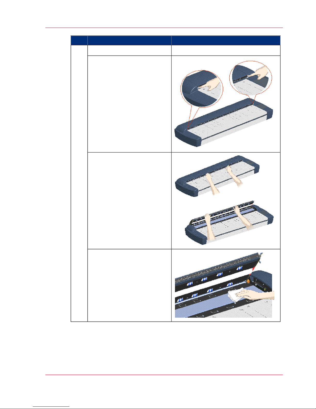
RemarksAction
Wipe the glass plate6
1. Open the scan area lid - Push
down on the two lock buttons
found near the insertion slot on
each side of the lid.
2. Disengage the scanning area
lid locking mechanism.
3. Place your thumbs in the insertion slot and flip the scanning
area lid back to its open position.
4. The glass plate is now exposed
for cleaning.
5. Wipe the glass plate with a dry
cloth to remove any dust.
6. Close the scanner lid. Make
sure the locks reengage (click).
Chapter 2 - Installation 15
Installation
Page 16
RemarksAction
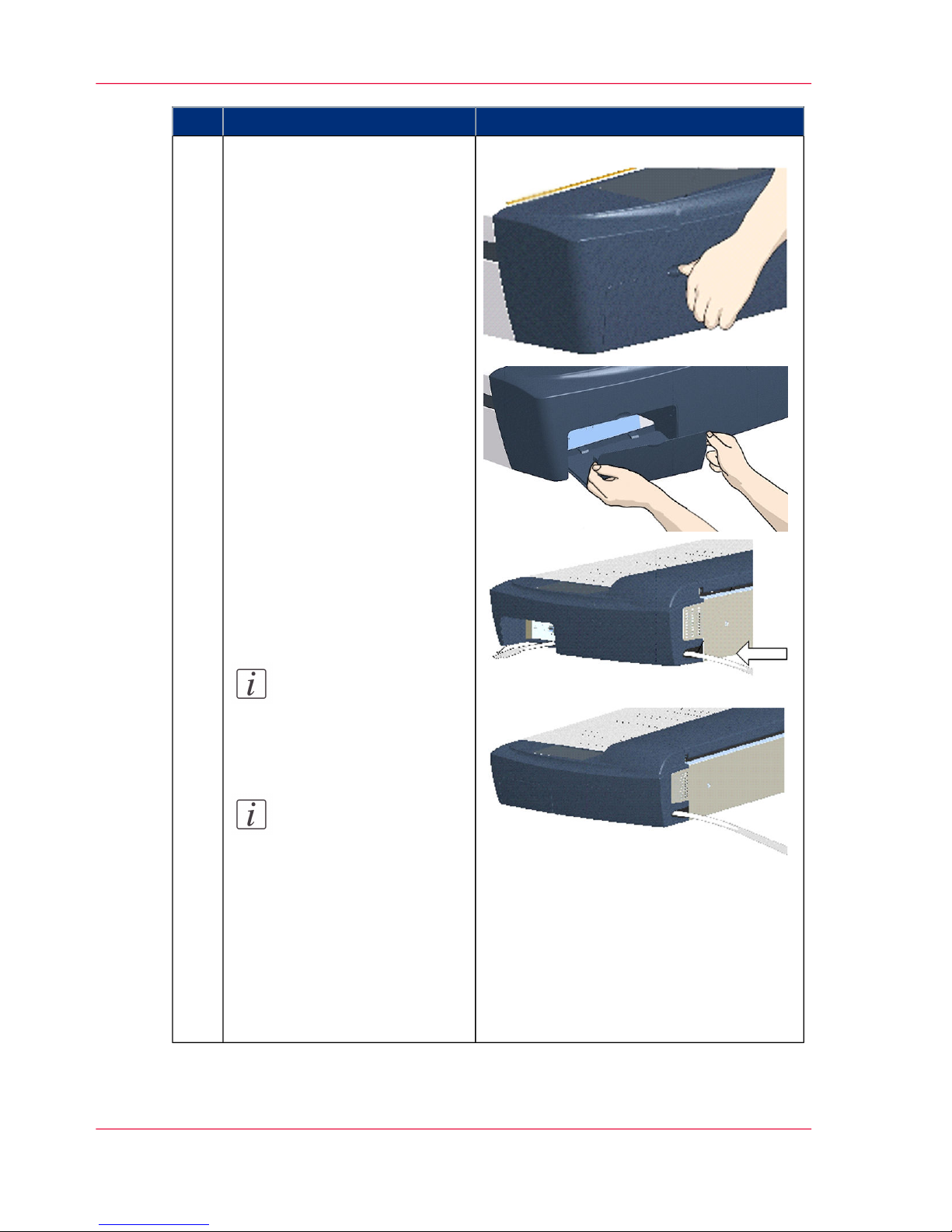
Connect interface cable to the
scanner
The cable connector panel is behind the cover at scanner’s right
side. You have to remove the
cover to connect the cable. Insert
your thumb in the slot at the top
of the cable connector panel
cover. Push down to snap the lid
open. .
Remove the cover with both
hands
Feed the interface cable’s B-connector (square shaped) end
through the opening in the back
of the scanner until it emerges
in front of the cable-connectorpanel. Thenconnect the B-connector to the USB connection
socket on your scanner
Connect the cable and close the
cable connector panel cover
Note:
The cover must always
be closed before you
turn the scanner ON.
Note:
Your scanner product
has been tested to comply with the EMC Standards EN55022 and
FCC, Part 15. To maintain compliance, only
use the interface cables
supplied with the scanner.
7
Chapter 2 - Installation16
Installation
Page 17
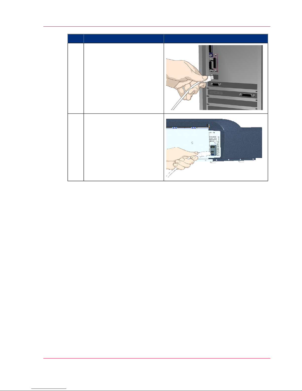
RemarksAction
Connect the other end of the
interface cable to the PC
USB connection: Connect the
A-connector end (flat end) to a
USB port on your computer.
8
Connect the power cable to the
scanner
Connect the scanner power cable
to the scanner‘s main power
connection socket. The main
power connection socket is at the
scanner’s backside..
9
Chapter 2 - Installation 17
Installation
Page 18
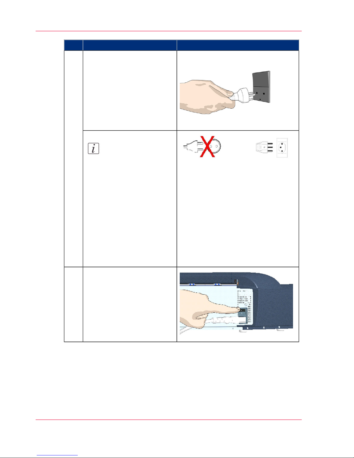
RemarksAction
Connect power to the wall
outlet
Connect the other end of the
scanner power cable to the power
outlet.
10
Note:
The scanner is equipped
with a three-wire (pin)
grounding type plug. If
you cannot insert the
plug into your outlet,
contact your electrician
to replace the plug or
outlet to ensure a
grounded power connection. Do not try to defeat or ignore the purpose of the groundingtype plug.
Switch on the scanner.
Switch on the main power
switch at the back of the scanner.
11
Chapter 2 - Installation18
Installation
Page 19
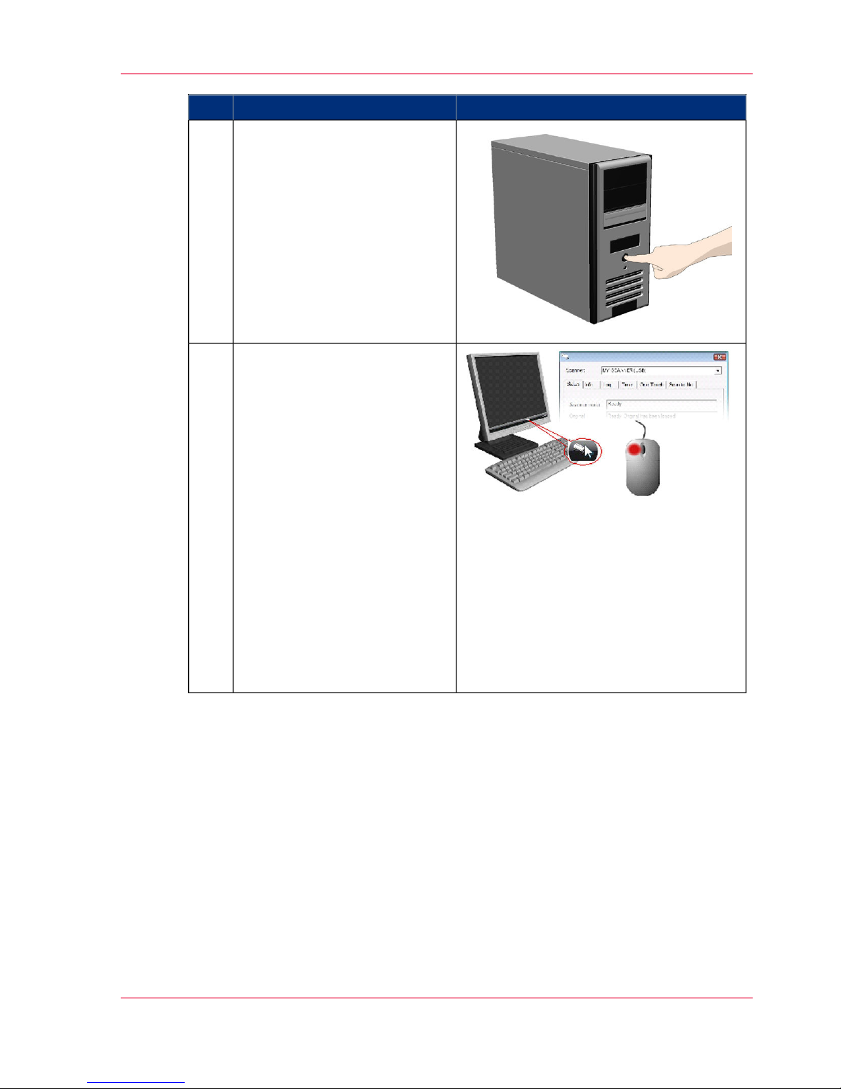
RemarksAction
Switch on your PC and start
Windows.
Windows will detect the new
hardware (scanner) during startup and the drivers you installed
in step 2. will be recognized.
Follow Windows' hardware installation instructions should any
appear on your screen.
12
Verify correct scanner installation:
1. Locate the scanner icon on the
Windows System Tray.
2. Left -double-click on the program icon.
3. Your scanner is installed and
detected if your scanner's name
appears at the top of the tab dialog.
4. If the scanner was not installed correctly, a message will
inform you that your scanner
could not be detected.
If this is the case turn off power
to all connected devices and repeat the installation steps.
13
Chapter 2 - Installation 19
Installation
Page 20
RemarksAction
Calibrate - Run scanner maintenance program
This step will ensure that your
cameras are aligned.
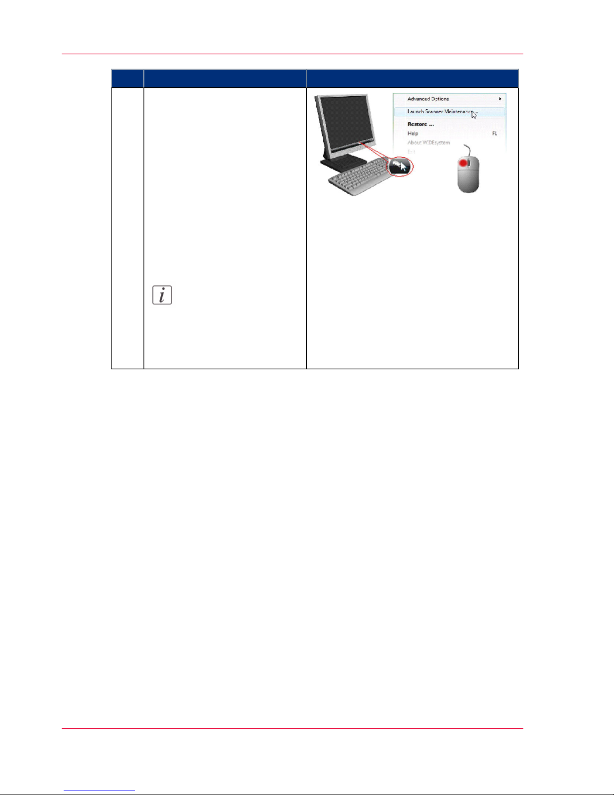
1. Right click on the scanner
icon .
2. Select Launch Océ Scanner
Maintenance.
3. Follow the instructions on
your screen.
See ‘Camera Alignment and Cali-
bration’ on page 69
Note:
The best quality of a
calibration is generated
after 1 hour warming-up
of the scanner lamp.
14
Chapter 2 - Installation20
Installation
Page 21

Chapter 3
The Operator's Panel
o
Page 22

The operator's panel
The operator's panel consists of buttons and LED indicators.
There are buttons for power ON/OFF, paper feeding, and triggering applications (one
touch).
The LED indicators function is to display scanner status in relation to its basic operations
such as self-testing and media readiness.
Operation of the buttons and interpretation of the LED indicator light patterns are described in the next user guide sections:
■
Power ON/OFF,
■
Loading the scanner,
■
Scanning thick media.
Chapter 3 - The Operator's Panel22
The operator's panel
Page 23
Overview of the Operators Panel and LED indicators
Introduction
The panel consists of operation buttons and LED indicators.
There are buttons for power ON/OFF, paper feeding, and triggering applications (onetouch).
The LED indicator’s function is to display scanner status in relation to its basic operations
such as self-testing and media readiness.
Operation of the buttons and interpretation of the LED indicator light patterns are described in this section.
Illustration
#
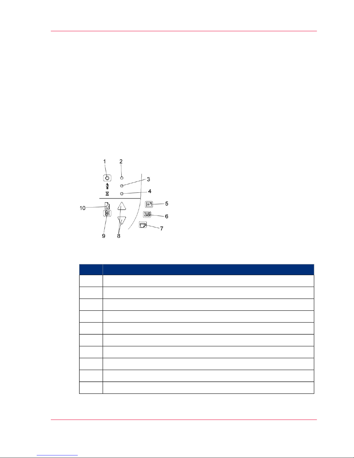
DescriptionStep
Power Key1
Power LED2
Diagnostics LED3
Wait LED4
Email application5
Scan Application6
Copy Application7
Paper Forward / Reverse keys8
ATAC key9
Paper Ready LED10
Chapter 3 - The Operator's Panel 23
Overview of the Operators Panel and LED indicators
Page 24

Power Control, Buttons and LED patterns
Introduction
The following table describes the panel’s LED light patterns and what they mean. The
illustrations marked “startup – phase 1 (2,3,4)” show how the Operator’s panel will look
(LED lighting patterns) starting from when you turn the Main power switch ON, through
the self-test procedures and until the scanner is ready to scan.
Note:
For simplicity, the illustrations below display a Standard Panel i.e., without an ATAC
key. The LED behavior of the Power LED, Diagnostics LED and Wait LED, are identical for Standard and ATAC operator’s panels.
Overview
#
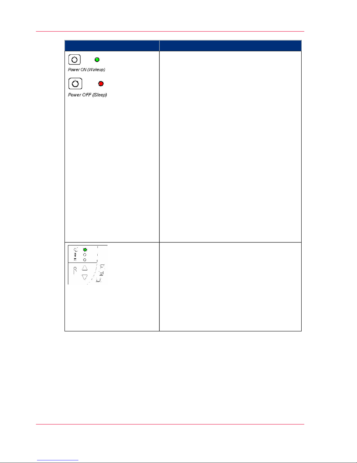
What it meansHow it looks on the scanner
Turn the scanner power ON – First Time – Main
Power ON At back of the scanner, plug in the
power cable and flip the main power switch to
ON. The scanner starts the selftest procedure
which starts with the Init Sequence
Init Sequence (startup phase 1)
When you turn main power On, the scanner runs
it initialization sequence. ALL the LEDs are
lighted as shown in the illustration on the left. At
this point, panel input is disabled and you cannot
begin scanning.
Note:
When you power up through Wake-up,
(by pressing the power key), this initialization sequence is skipped and the scanner
goes directly to Self-Adjustment (startupphase 3).
Power LED Green (startup – phase 2)
Towards the end of Init Sequence, the Power LED
will change to green while the other LEDs remain
unchanged (lighted). From here the scanner moves
on to Self Adjustment (startup phase 3).
Chapter 3 - The Operator's Panel24
Power Control, Buttons and LED patterns
Page 25

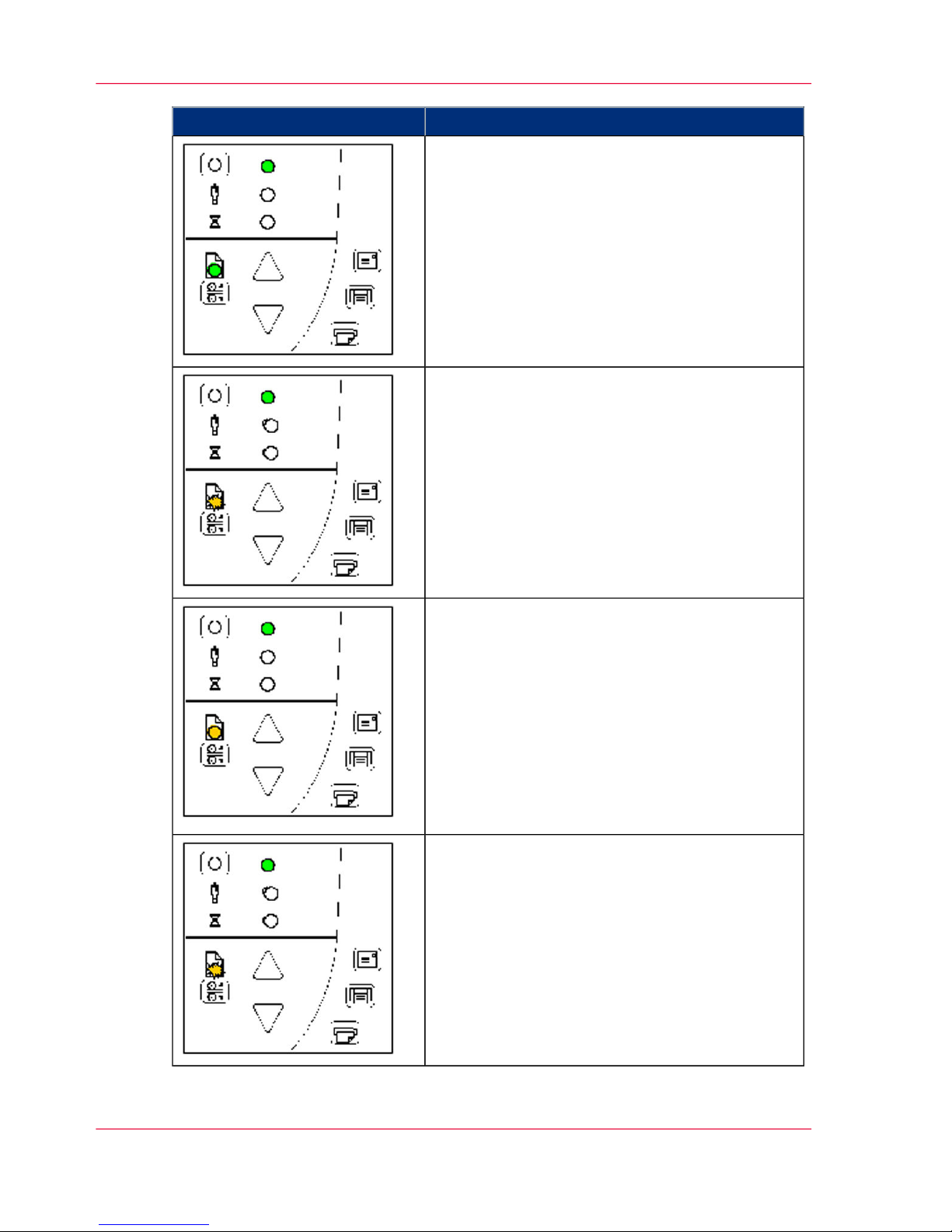
What it meansHow it looks on the scanner
Self-Adjustment (startup –phase 3)
On completion of the Init Sequence, the power
LED (green) and the Wait LED (yellow) remain
lighted while the others LEDs turn off. This indicates that the scanner is running its Self-Adjustment of light profiles, stitching and black/white
points.
Note:
To maintain optimal conditions, the
scanner runs new Self-adjustment procedures periodically during the day (without
lighting the wait LED). If the Wait indicator blinks, the scanner needs to run SelfAdjustment but cannot
Scanner Ready (startup – phase 4)
When the Wait LED turns off, and only the
Power LED is ON and lights green, self-adjustment is completed and the scanner is ready to scan.
Chapter 3 - The Operator's Panel 25
Power Control, Buttons and LED patterns
Page 26
What it meansHow it looks on the scanner
Wake-up / Sleep - Turn power ON/OFF with
power key – normal use (with main power switch
always ON)
With the outlet switch always ON, use the Power
key to control scanner power. Hold down on the
Power key to toggle power into Wakeup and Sleep
modes. The Power LED lights green when the
scanner is ON (Wake-up) and red when power is
OFF (Sleep). When you turn the scanner ON in
this manner, it skips the init sequence and starts
with Self-Adjustment as described above for startup
phase 3.
When in the power Wake-up/Sleep mode: The
scanner can be manually powered up and down
(wake and sleep) by pressing and holding down
the power button or inserting a document for
scanning.
See Power, Wake/sleep and Adjustment.
The scanner can automatically be powered up and
down (wake-up/sleep) by Océ Scanner Agent timer
or idle time setting.
See Automatic Power functions
Green Power LED blinking
The green power LED will blink just before the
scanner automatically powers off because its defined automatic Sleep time (in WIDEsystem) has
been reached in the timer. If you are still using the
scanner and want to cancel the timer controlled
Sleep mode, press the power key until the LED
stops blinking. You can at any time disable or
change timer settings in Océ Scanner Agent (see
Océ Scanner Agent on-line help for details).
Chapter 3 - The Operator's Panel26
Power Control, Buttons and LED patterns
Page 27

What it meansHow it looks on the scanner
Wait LED blinking - Self-Adjustment required
but not possible
If the Wait LED blinks (and the Diagnostics LED
is off) the scanner needs to run Self-Adjustment
but cannot. Self- Adjustment is necessary for
maintaining optimal and stabile internal conditions. To solve this, any original in the scanner
should be removed, and the pressure-platen should
be set to the Normal position (i.e., not a thick
media setting). A scan may be issued, but the
quality will be compromised. When Self- Adjustment is again possible, the Wait LED stops blinking, but continues to be on until Self-Adjustment
is completed. The scanner should be left alone
while Self-adjustment is running.
During Calibration – Wait LED lights
This is normal. The Wait LED is on during Calibration to indicate that the original should not be
removed or moved during the Calibration procedure. All panel input is prevented during basic
calibration.
Diagnostics LED blinking – Error detected during
Self-Test
The Diagnostics LED shows the scanner’s SelfTest result status. An unlit Diagnostics LED means
that the scanner’s Self-Test procedures encountered
no errors. If the Diagnostics LED blinks, an error
was discovered during Self-Test.
Open Océ Scanner Agent (double-click the scanner
icon on your system tray) and select the Status tab
to view additional information about the error.
Chapter 3 - The Operator's Panel 27
Power Control, Buttons and LED patterns
Page 28

What it meansHow it looks on the scanner
Both Diagnostic LED and Wait LED blinking –
Maintenance needed
Simultaneous blinking by both the Diagnostic
LED and the Wait LED may mean that the scanning area needs cleaning and the cameras calibrated. See the section on "Maintenance" for instructions. If the Diagnostic and the Wait LEDs continue to blink after scanner maintenance, there
may be camera position errors that requires Océ
service.
Chapter 3 - The Operator's Panel28
Power Control, Buttons and LED patterns
Page 29

Media Control – Buttons and LED Patterns
Introduction
Your panel contains LEDs and buttons for controlling the media you insert for scanning.
The following basic functionality applies on all models:
1.
The Paper Ready LED lights up when the media is inserted into the original’s insertion
slot and correctly positioned for feeding on a straight path. It lights green for normal
documents and yellow for thick media scanning.
Note:
See also this guide’s sections on loading originals and Scanning Thick Media
2.
The media can then be moved into the start-scan position by pressing the Paper Forward
Key or through automatic loading.
3.
The Paper Ready LED will blink during scanning.
4.
The media can be moved back for ejection by pressing the Paper Reverse key.
Overview
#
DescriptionHow it looks on the scanner
Paper Forward and Paper Reverse Keys
The Paper Forward Key moves the drawing into
the start-scan position for manual loading (see
section on Loading). If Auto-Load is set, loading
will occur automatically (without pressing the key)
when the original enters the insertion slot. Pressing
the Paper Forward Key during scanning will stop
the scanning process and feed the original through
the scanner while the key is held down. The Paper
Reverse Key stops the current scanning process
and reverses the original. The original will be fed
backwards through the scanner while the key is
held down. When the scanner is in Automatic
Thickness Adjustment Control (ATAC) mode the
paper forward and paper reverse keys become
“pressure-platen up” and “pressure-platen Down”
keys (see below).
Chapter 3 - The Operator's Panel 29
Media Control – Buttons and LED Patterns
Page 30
DescriptionHow it looks on the scanner
Paper Ready LED Green - Ready for Normal media
The Paper Ready LED lights green when normal
thin media is positioned correctly in the insertion
slot and stays green when the media is moved to
the start-scan position. From there, scanning can
be controlled from the computer.
Paper Ready LED blinks Yellow – Scanner in
ATAC mode
When you press the ATAC key, you set the scanner in ATAC mode. The Paper Ready Key blinks
yellow to indicate ATAC mode. The Paper Forward and Paper Reverse keys become “Pressureplaten Up” and “Pressure-platen Down” keys.
Paper Ready LED Yellow - Ready for Thick media
The Paper Ready LED lights yellow when the
scanner is ready to scan thick media. The pressureplaten has been lowered and the media is positioned correctly in the scanner. The scanner goes
automatically out of ATAC mode. The Paper
Forward and Paper Reverse keys resume their
normal functionality so you can move the thick
original forwards and backwards in the scanner.
Scanning can be controlled from the computer.
Paper Ready LED blinks – (green or yellow) –
Media is being scanned
The Paper Ready LED blinks during scanning.
On completion of the scan, the Paper Ready LED
will stop blinking. Scanning can then be repeated
from the computer or terminated by ejecting the
media from the scanner. The above behavior applies for both thin media scanning (green blinking)
and thick media scanning (yellow blinking).
Chapter 3 - The Operator's Panel30
Media Control – Buttons and LED Patterns
Page 31

DescriptionHow it looks on the scanner
Paper Ready LED Red – No Thick media detected
The paper ready indicator will light red if the
pressure-platen is in a thick media setting (a raised
pressure-platen) but no media is detected in the
scanner.
Chapter 3 - The Operator's Panel 31
Media Control – Buttons and LED Patterns
Page 32

Chapter 3 - The Operator's Panel32
Media Control – Buttons and LED Patterns
Page 33

Chapter 4
Turning Power ON/OFF Wake/Sleep Mode
o
Page 34

Main Power ON/OFF
The main power switch is at the back of the scanner.
■
Press the upper half of the switch (marked “I”) to turn the main power to ON.
■
Press the lower half of the switch (marked “0”) to turn the main power to OFF.
Chapter 4 - Turning Power ON/OFF - Wake/Sleep Mode34
Main Power ON/OFF
Page 35

The scanner’s Self Test Procedure
Introduction
When you connect the scanner to the power outlet and turn on the outlet switch at the
back of the scanner, it starts up with a self-test procedure.
The scanner’s self-test procedure consists of two main steps:
1.
Init (Initialization) Sequence
The scanner loads and tests internal parameters.
Only initiated when you turn the main power ON.
The panel’s LEDs will be lit as shown in the next illustration:
Chapter 4 - Turning Power ON/OFF - Wake/Sleep Mode 35
The scanner’s Self Test Procedure
Page 36

2.
Self-Adjustment
Adjustment of light profiles, stitching and black/white points.
Starts after the Init Sequence when the scanner’s main power switch is turned ON or
right away when the scanner goes from sleep to wake mode.
The panel’s LEDs will be lit as shown below:
Chapter 4 - Turning Power ON/OFF - Wake/Sleep Mode36
The scanner’s Self Test Procedure
Page 37

Scanner ready to scan
You will know that the self-test procedures have completed and the scanner is Ready
when the Power LED is lighted green and the other LEDs are off as shown below:
Chapter 4 - Turning Power ON/OFF - Wake/Sleep Mode 37
Scanner ready to scan
Page 38

Wake and Sleep modes
Introduction
With the main power switch ON, scanner power can be set in Sleep mode and Wake
mode. Sleep mode is the energy saving mode.
The scanner cannot scan when in the Sleep mode.
Wake mode is the full power ON mode for scanner operation.
The scanner will go from Wake mode into Sleep mode:
■
Automatically: after a set idle time (see Automatic Power functions).
■
Automatically: with the Timer (see Automatic Power functions).
■
Manually: when you hold the power button down for 3 seconds.
The scanner will go into wake mode:
■
Automatically: with the Timer (see Automatic Power functions).
■
When you feed a document into the scanner.
■
When you press any button on the panel.
Advantages with using Wake-up and Sleep modes:
Ready faster:
You turn the scanner OFF and ON (sleep/wake-up) by pressing the power key on the
panel. The scanner skips its init sequence and is ready to scan sooner than with Main
Power OFF to ON.
Convenience:
When OFF (LED is red) the scanner can be powered up (Wake-up) easily by pressing
the power key or just by inserting paper into the scanner, thereby indicating you wish to
scan.
Timer function:
Scanner power with Wake-up and Sleep, can be setup and controlled through the Océ
Scanner Agent software timer week schedule feature or through an idle time setting.
Save energy:
Sleep mode runs at low power values.
Chapter 4 - Turning Power ON/OFF - Wake/Sleep Mode38
Wake and Sleep modes
Page 39

Automatic Power ON/OFF
Automatic Power ON/OFF
Introduction
Automatic power management lets you schedule your scanner’s up-time optimally and
helps save energy.
You can set the scanner for automatic power OFF (Sleep) and power ON (Wake-up).
Automatic power management functionality is set and controlled through your Océ
Scanner Agent software.
There are two automatic power functions:
■
Timer function
■
Enter Sleep mode automatically (after idle time) option.
Note:
In order to use automatic power management functionality: the scanner Main Power
switch at the scanner’s back must be turned ON.
The power LED on the operator’s panel will light red when the scanner is in Sleep Mode
(powered OFF) and green when in Wake Mode (powered ON).
Chapter 4 - Turning Power ON/OFF - Wake/Sleep Mode 39
Automatic Power ON/OFF
Page 40

Timer Function - Scheduling ON/OFF Times
Introduction
You can program your whole weekly schedule into the scanner so it powers ON and OFF
(wake – sleep) on its own. You enter your schedule’s wakeup and sleep times in Océ
Scanner Agent Timer tab as shown in the example below. .
To set the Timer:
1.
Open Océ Scanner Agent. Double-left-click the scanner icon in the system tray.
2.
Select the Timer Tab.
3.
Click the checkmark fields for each day you want automatic wake-up and sleep actions.
Chapter 4 - Turning Power ON/OFF - Wake/Sleep Mode40
Timer Function - Scheduling ON/OFF Times
Page 41

4.
Under the Wake-up column - Click on the hour digits in the day’s edit field to highlight
them. Use the arrow box to increase or decrease the hour value or use your keyboard to
write the value in the field.
5.
Move to the Wake-up column’s minute digits for the same day - Click on the minute
digits in the day’s edit field to highlight them. Use the arrow box to increase or decrease
the hour value or use your keyboard to write the value in the field.
6.
Repeat this process in the Sleep column for the same week-day.
7.
Make settings for the other week-days in the same manner or….
8.
You can use the Link Monday to Friday option to make your settings for Monday apply
for the whole work-day-week.
Note:
The Idle time before sleep time setting will still apply and may conflict with your Timer
settings. Change or disable the Idle time before sleep time setting if it does.
9.
When you have filled out the dialog, press Apply to download your settings into the
scanner’s memory.
When the Timer is active:
Your scanner will store and remember your settings so you have them after you turn off
your PC and shutdown Océ Scanner Agent program. When you restart Océ Scanner
Agent, the Timer tab will display the values currently stored in the scanner.
If the scanner is being used, it will delay entry into Sleep mode. The power LED on the
panel will blink just before entry into a scheduled sleep mode. You can cancel entry into
Sleep mode by pressing the power button.
Chapter 4 - Turning Power ON/OFF - Wake/Sleep Mode 41
Timer Function - Scheduling ON/OFF Times
Page 42

Automatic Shut Down after Idle Time
Introduction
On delivery, the scanner is set for automatic entry into sleep mode after a preset default
idle time, i.e. the length of time the scanner is not active.
You can prolong or shorten the idle time value to match your normal workflow.
To change/set the sleep mode options:
1.
Open Océ Scanner Agent. Double-left-click the scanner icon in the system tray.
2.
Select the Timer Tab.
3.
Select or deselect the Enter Sleep mode automatically option.
4.
If you do not select the Enter Sleep mode automatically option, you will need to use the
manual method for entering sleep mode by holding the power button down for 3 seconds.
5.
If you do select Enter Sleep mode automatically option, proceed to the next step to set
the Idle time value.
6.
Set the value Idle time before entering sleep. This is the number of minutes the scanner
can stand idle before entering the sleep mode on its own.
Chapter 4 - Turning Power ON/OFF - Wake/Sleep Mode42
Automatic Shut Down after Idle Time
Page 43

7.
Press Apply to download your settings into the scanner’s memory.
Note:
With the scanner main power ON, the scanner can be also be brought into Wake-up and
Sleep modes manually even while the Enter sleep mode automatically option is selected.
■
Wake - by pressing any button on the panel or inserting a document for scanning.
■
Sleep – by pressing and holding down the power button for 3 seconds.
You can choose to disable automatic entry into Sleep mode entirely if you want only
manual activation of the sleep mode or, you can leave it enabled and retain both manual
and automatic functions.
Chapter 4 - Turning Power ON/OFF - Wake/Sleep Mode 43
Automatic Shut Down after Idle Time
Page 44

Chapter 4 - Turning Power ON/OFF - Wake/Sleep Mode44
Automatic Shut Down after Idle Time
Page 45

Chapter 5
Loading Originals into the
Scanner
o
Page 46

Loading originals
Introduction
Load your document with the image side facing downwards.
Align the center of the document with the center arrow marking on the scanner bed.
Use the standard size markings to help align the document for a straight scan path.
You can use automatic loading or manual loading. These 2 loading options are selected
in the scan/copy application dialogs on your PC.
Read the instructions about Automatic and Manual loading in the next sections.
Note:
The availability of the automatic and manual loading options will depend on your software and its level of compatibility with the scanner model.
Note:
See also this manual section on Scanning Thick Media for instructions on loading thick
media originals.
Chapter 5 - Loading Originals into the Scanner46
Loading originals
Page 47

Automatic loading
Introduction
With automatic loading, the scanner takes the original as soon as you insert it in the paper
slot. Automatic loading is reliable for most jobs and especially useful for batch scanning
jobs.
Automatic loading
1.
Make sure the Paper handling option “Auto load” is set in your scanning application.
2.
Align the center of the document with the center arrow marking on the scanner bed.
3.
Push the original into the insertion slot until you feel it contact the rollers and the Paper
Ready LED lights green (yellow for thick media).
4.
The scanner will grab the original automatically and move it into startscan position.
5.
A delay factor can be set in the scanning application. The delay will give you time to
control straight positioning of the document in cases where the scanner is grabbing the
original too fast.
Chapter 5 - Loading Originals into the Scanner 47
Automatic loading
Page 48

Manual loading
Manual loading
1.
Make sure the Paper handling option “Manual” is set in your scanning application.
2.
Align the center of the document with the center arrow marking on the scanner bed.
3.
Push the original into the insertion slot until you feel it contact the rollers and the Paper
Ready LED lights green (yellow for thick media).
4.
While holding the original in place with one hand, use the other hand to press and hold
down the Paper Forward button on the scanner.
5.
The original moves into the start-scan position
Chapter 5 - Loading Originals into the Scanner48
Manual loading
Page 49

Unloading the original after scan
Unloading the original after scan
1.
Press the Paper Reverse button to eject the original back to the scanner feeding bed.
2.
Press the Paper Forward button if you wish to eject the original out the back of the
scanner.
Chapter 5 - Loading Originals into the Scanner 49
Unloading the original after scan
Page 50

Fast-loading
Introduction
What is Fast-loading? – With normal (default) loading, i.e. without the Fast-load option
selected, the original is pulled all the way into the drive system, past both roller axles, and
then reversed to start-scan position in order to ensure precise detection of the original’s
placement in the scanner. With the Fast-load option selected, the original is pulled only
under the first roller axle and scanning will start from there. The Fast-load option is
convenient for batch scanning of originals with robust edges that feed easily. Normally,
with batch scanning, you would use the Fast-load option in conjunction with automatic
loading however you can also use manual loading to feed the original into start-scan position.
Note:
The availability of the fast loading option will depend on your scan/copy software and
its level of compatibility with the scanner model.
Fast-loading
Fast-loading is a time-saving loading option designed for batch scanning. The fast-loading
option can be selected in the scanning application.
Chapter 5 - Loading Originals into the Scanner50
Fast-loading
Page 51

Soft-handling
Soft-handling
The Soft-handling option is selected in your scan application. Soft-handling means that
feeding and scanning are slowed down. You can use the option with both Manual and
Automatic loading.
Note:
The availability of the soft handling load option depends on your scan/copy software and
its level of compatibility with the scanner model.
Use Soft-handling with
1.
Old, curled or creased originals that trigger a paper jam. See Trouble Shooting – Paper
Jam error for correcting a paper jam error.
2.
Fragile originals you want passed delicately through the drive system.
Chapter 5 - Loading Originals into the Scanner 51
Soft-handling
Page 52

Setting the input size
The Input size defines the scan area. You enter the input size in your application’s input
size dialogs.
Note:
The availability of the Input size options described below will depend on your scan/copy
software and its level of compatibility with the scanner model.
3 ways to set find and set the input size:
1.
Use automatic size detection
The scanner will detect the edges of the document and calculate the input size for you.
2.
Set a standard size
Common standard sizes are marked on the scanner bed.
Use these markings to determine which standard size matches the original and then select
that size in the application’s input size dialog.
3.
Set the size manually for irregular sizes.
To measure your document - use the scanner’s ruler just above the insertion slot. Enter
your width measurement in the width setting field in your application’s input size setup
dialog. You can measure and set a length value or choose automatic length detection.
Chapter 5 - Loading Originals into the Scanner52
Setting the input size
Page 53

Chapter 6
Scanning
o
Page 54

Software applications for scanning
Introduction
Your scanner is controlled through scan, copy or imaging software installed on your PC.
Optimal full featured scanning functionality
is obtainable through scan and copy software specifically developed for compatibility with
your scanner model.
See the scanner manufacturer’s website for information on scanner software and compatible third-party applications.
Simple scanning functionality
Many common imaging applications support TWAIN and WIA interfacing and will
thereby support simple scanning tasks through a limited range of settings and control
options.
Chapter 6 - Scanning54
Software applications for scanning
Page 55

Running applications from the scanner panel
Definition
Normally you would control the scanner from your PC through your scan software user
interface.
However, your scanner also supports one-touch buttons that enable you to trigger your
software from the scanner panel. When a button is pressed, a scan is initiated and the
result is loaded into the application triggered.
You configure your one-touch buttons through Océ Scanner Agent and your compatible
scanning software. Please refer to the on-line help in these applications for instructions.
Note:
See Appendix A – Overview of the Operator’s Panel - ApplicationControl – One Touch
Scan for additional information.
Illustration
Chapter 6 - Scanning 55
Running applications from the scanner panel
Page 56

Batch scanning
Introduction
Batch scanning involves jobs where you want to feed and scan a whole set of originals
that require equal scan settings.
1.
Set your scan settings (size, type, image adjustments..) for the batch. Your settings will
apply to ALL the documents in the batch.
2.
Set the scan software into Batch Mode. This will tell the scanner to start scanning as soon
as the document is fed so you don’t need to trigger the scan.
3.
Choose Automatic loading (optional) - for fast and effective loading. Read you scan
software’s on-line help pages for specific information on batch scanning with the application.
Note:
The availability of Batch scanning options will depend on your scan/copy software and
its level of compatibility with the scanner model.
Chapter 6 - Scanning56
Batch scanning
Page 57

Chapter 7
Scanning Thick Media
o
Page 58

Scanning Thick Media
You may need to scan documents and drawings printed or pasted on thick media such
as cardboard, foamboards, gatorboards etc.
To do so, you will need to fit the insertion slot to the thickness of your original.
This is done by raising the pressure-platen to the exact correct height.
Chapter 7 - Scanning Thick Media58
Scanning Thick Media
Page 59

Automatic Thick Media Adjustment
Introduction
Scanners with Automatic Thickness Adjustment Control (ATAC) have an ATAC key
on the operator’s panel.
You use the key to raise and lower the pressure-platen. You can change the insertion slot
size (pressure-platen height) on your scanner from 2mm to 15 mm (up to 0.6”).
Originals up to 2mm thickshould be scanned with the pressure all the way down (normal
position). Thicker originals will require you use the ATAC key to adjust for thick media.
To adjust the insertion slot for thick media with ATAC:
1.
Press the ATAC key on your operator’s panel to set the scanner in ATAC mode.
2.
The Paper Ready Indicator blinks yellow indicating the scanner is in ATAC mode but
not yet ready, i.e., the pressure-platen is not yet positioned for the thick original.
3.
Press and hold the Paper Forward key (arrow up) key to raise the pressure-platen until
there is room to insert the thick original.
4.
Insert the thick original evenly for a straight scan path.
5.
Press and hold the Paper Reverse (arrow down) key to lower the pressure-platen until the
pressure-platen stops on its own.
6.
The Paper Ready indicator will stop blinking and remain yellow when the pressure-platen
is positioned correctly and is ready for thick media scanning.
Chapter 7 - Scanning Thick Media 59
Automatic Thick Media Adjustment
Page 60

7.
The scanner will automatically leave the ATAC mode, which means that the Paper Forward
and Paper Reverse keys will return to their normal functionality for moving the original
forwards and backwards.
Chapter 7 - Scanning Thick Media60
Automatic Thick Media Adjustment
Page 61

When Scanning in Thick Media Positions
Introduction
The scanner employs an automatic self-adjustment procedure (light profile, stitching etc.)
that can only activate itself when the scanner is in the Normal position.
With prolonged scanning in extended thickness settings, you should from time to time
return the scanner to its Normal position to allow it to self-adjust.
This will ensure refreshed self-adjustment and optimal performance of your scanner.
Make a habit of always setting the scanner in the Normal position when shutting down,
so it can auto-self-adjust the next time you turn it ON.
Before you begin
Remember to return to the Normal position so the scanner can run Auto-Self-Adjustment
Modifying Stitching Parameters
Thick stiff originals will rest on top of the scanner rollers and thus raise a small distance
over the glass-plate. This can lead to irregularities in relation to “stitching” of the image
at points between the cameras (overlapping pixels). In such cases, the stitching parameters
will need to be modified. You can modify stitching parameters through your scanning
application in the following way:
1.
Insert your thick original in the scanner and scan the image using your scanning application.
2.
Check the result in the viewer for overlapping or missing pixels in the camera transition
areas.
3.
Adjust the stitching values in the application’s scanner setup dialogs.
4.
Repeat scanning and adjustment until the effect is minimized.
Chapter 7 - Scanning Thick Media 61
When Scanning in Thick Media Positions
Page 62

Chapter 7 - Scanning Thick Media62
When Scanning in Thick Media Positions
Page 63

Chapter 8
Maintenance
o
Page 64

About scanner maintenance
Introduction
Scanner maintenance will ensure optimal performance of your scanner.
There are three basic maintenance tasks:
■
Cleaning
Keep your scanner clean – the next section describes how to thoroughly clean the internal scan area. How often you need to clean the scanner will depend on how often
and the types of media you scan. If your work primarily involves scanning newspapers
and old blueprints you may need to clean more often than users who only scan
brochures and new drawings. Be sure to clean the scanner when results are not optimal.
Particles of dust in the scan area can often be the cause of streaks in the end result.
See ‘Cleaning the Scan Area’ on page 65
■
Calibration and camera alignment
Scanner Calibration is easy to perform and most of it is completely automatic. Scanner
calibration includes camera alignment and calibration of B&W and color parameters.
To run, you insert a Calibration Sheet, and start the Scanner Maintenance program.
Be sure to calibrate if your output is not optimal. Make sure the scanner is clean before
calibrating. See ‘Camera Alignment and Calibration’ on page 69
■
Replacing worn parts
This should be carried out when you get a warning on your screen or when a worn
part affects your results.
Replaceable parts are:
a. the glass plate. See ‘Replacing the glass-plate’ on page 73
b. the lamp. See ‘Replacing the Scanner Lamp-Unit’ on page 81
c. the white background platen. See ‘Replacing the White-background platen’ on page
77
d. the dust filters. See ‘Replacing the Dust-Filters’ on page 84
Request replaceable parts at mediaguide.oce.com.
Chapter 8 - Maintenance64
About scanner maintenance
Page 65

Cleaning the Scan Area
Introduction
You only need to open the lid to access the scan area when cleaning the scanner. Follow
the instructions below.
Caution:
Do not spray liquids directly onto the scanner glass-plate.
Caution:
Make sure the scanner power is OFF when using the dust cover.
#
RemarksAction
Turn scanner power off
Press the main power switch
(scanner back) to OFF and disconnect the power plug.
1
Chapter 8 - Maintenance 65
Cleaning the Scan Area
Page 66

RemarksAction
Open the scanner’s lid
1. Open the scan area lid - Push
down on the two lock buttons
found near the insertion slot on
each side of the lid.
2. The scanning area lid locking
mechanism should now be disengaged.
3. Place your thumbs in the insertion slot and flip the scanning
area lid back to its open position.
2
Clean the glass-plate
The glass-plate is now exposed
for cleaning.
1. Clean the glass with a lint-free
cloth and a mild, streak-free,
glass cleaner. Apply the cleaner
to cloth and wipe the glass-plate.
2. Dry the glass completely using
a separate clean, dry lint-free
cloth like the one provided with
the maintenance kit.
Caution: Do not spray liquids
directly onto the scanner glassplate.
3
Chapter 8 - Maintenance66
Cleaning the Scan Area
Page 67

RemarksAction
Clean the white-background
platen and upper rollers
The white-background-platen
(white metal area) is fixed in the
scanning area lid. The upper
rollers are aligned in 2 rows on
each side of the white-background-platen.
1. Hold/support the lid in its
open position for support as you
clean.
2. Use a lint-free cloth and a
mild, streak-free, glass cleaner.
Apply the cleaner to cloth and
wipe the white-backgroundplaten.
3. After wiping clean the whole
white background platen, wipe
all the upper rollers in both rows.
4. Dry the platen and rollers
completely using separate clean,
dry lint-free cloths.
Caution: Do not spray liquids
directly onto the scan area.
4
Clean the lower rollers
The lower rollers are the black
rubber rollers aligned in 2 rows
on each side of the glass-platen.
1. Use a lint-free cloth and a
mild, streak-free, glass cleaner.
Apply the cleaner to cloth and
wipe the lower rollers in both
rows. 2. Dry the lower rollers
completely using a separate
clean, dry lint-free cloth.
2. Dry the lower rollers completely using a separate clean, dry lintfree cloth.
Caution: Do not spray liquids
directly onto the scan area.
5
Chapter 8 - Maintenance 67
Cleaning the Scan Area
Page 68

RemarksAction
Close the scanning area lid.
1. Pull down and close the scanning area lid when finished.
2. Press gently down on the cover top to make sure the locks
reengage (click).
6
Clean the scanner feed area
surface
Clean also the scanner surface so
dirt and dust are not dragged into the scan area with the original.
7
Cover when not in use
Cover the scanner with its plastic
dust cover when not in use.
Caution: Make sure the scanner
power is OFF when using the
dust cover.
8
Chapter 8 - Maintenance68
Cleaning the Scan Area
Page 69

Camera Alignment and Calibration
Introduction
Scanner calibration is very easy to perform with the Scanner Maintenance program you
installed with your drivers.
After manually cleaning the scan area, you just insert a calibration sheet, start the Scanner
Maintenance program and let the wizard take over.
Note:
Cleaning and calibration are tied together. Cleaning the scanner creates the need for
renewed calibration and correct calibration will always require a clean scan area.
Note:
The best quality of a calibration is generated after 1 hour warming-up of the scanner
lamp.
#
RemarksAction
Turn the scanner power ON
Make sure that the scanner has
been turned ON for at least 5
minutes prior to camera alignment and calibration. The short
warm-up time will ensure that
light conditions and camera
heights have stabilized
1
Launch the scanner maintenance program
1. On your PC - Right click on
the scanner icon
2. Select Launch Scanner Maintenance to open the program’s
welcome dialog.
2
Chapter 8 - Maintenance 69
Camera Alignment and Calibration
Page 70

RemarksAction
Follow the steps described by
the wizard
The scanner maintenance wizard
will guide you through the
alignment and calibration steps.
Click the Next button in the
welcome dialog to proceed.
3
Insert the calibration sheet
During the process, the wizard
will ask you to insert the Calibration Sheet that came with your
scanner. The sheet’s printed side
must be inserted face down.
Align the sheet’s midpoint arrow
with the scanner’s midpoint arrow and feed the sheet into the
scanner.
Click the wizard’s Next button
to continue.
4
The program aligns and calibrates the scanner
The program works in steps to
analyze and correct the alignment and stitching status of the
cameras, calibrate black and
white values and calibrate color.
The calibration sheet will be rescanned a number of times as the
program processes data.
Let the program complete all
alignment and calibration steps.
5
Chapter 8 - Maintenance70
Camera Alignment and Calibration
Page 71

RemarksAction
Finished
The wizard will tell you when
the process is finished.
1. Remove the Scanner Calibration Sheet from the scanner.
2. Return the Scanner Calibration Sheet to its protective cover
and then place it in the storage
folder. Store the folder in a dry
place and out of direct light.
6
Chapter 8 - Maintenance 71
Camera Alignment and Calibration
Page 72

Replacing Scanner Parts
Replacing scanner parts
Introduction
This section describes how to replace those scanner parts that are liable to wear down
over long-term use. Changing parts will renew your scanner and reestablish optimal results.
Océ Scanner Agent monitors scanner usage and will warn you when it is time for a replacement.
Note:
Regarding Océ Scanner Agent warning flag - glass plate and White background platen
replacement: After receiving a warning by Océ Scanner Agent and replacing the part,
be sure to reset the part replacement warning flag through the Océ Scanner Agent
“Status” tab.
Note:
Regarding RECALIBRATION - glass plate, White background platen, lamp unit replacement: Replacing these parts will change conditions in the scan area. Therefore, it
is recommended to recalibrate right after changing and cleaning these parts.
Caution:
Instruction: Before replacing any parts, be sure to turn the scanner power off and disconnect the power plug.
Chapter 8 - Maintenance72
Replacing scanner parts
Page 73

Replacing the glass-plate
#
RemarksAction
Note:
Turn the scanner power
off and disconnect the
power plug.
1
Open the scan area lid - Push
down on the two lever buttons
found near the insertion slot on
each side of the lid.
2
The scanning area lid locking
mechanism should now be disengaged
3
Chapter 8 - Maintenance 73
Replacing the glass-plate
Page 74

RemarksAction
Place your thumbs in the insertion slot and flip the scanning
area lid back to its open position
4
The glass-plate will be exposed
and accessible.
5
On each side of the glass-plate
there is a small lever with a
round lever-handle on its end.
Place a finger under both round
lever handles on each side of the
scanner.
6
With both arms, pull simultaneously on the left and right levers
to flip the glass-plate towards
your body so it tilts upwards and
is fee from the scan area bed.
7
Chapter 8 - Maintenance74
Replacing the glass-plate
Page 75

RemarksAction
Each lever is attached to the
scanner chassis with a small hook
that rests on a round pin. As you
hold the glass-plate on both its
edges, lift it upwards to detach
both lever’s hooks from the pins
and thus free the glass-plate from
the scanner.
8
Reverse the above operations to
reinsert a new glass-plate –
Carefully set the new glass plate
down into the scan area. Fit the
new glassplate’s lever hooks on
to the round pins on each side
of the scanner as shown.
9
While supporting the glass-plate
with fingers on the lever handles,
carefully ease the glass-plate
down backwards (away from
your body) so it falls into place.
10
Chapter 8 - Maintenance 75
Replacing the glass-plate
Page 76

RemarksAction
Close the scan area lid.
Note:
It is recommended to
clean the new glass-plate
after inserting it in the
scanner and before scanning.
Note:
It is recommended to
calibrate after changing
the glassplate.
11
Chapter 8 - Maintenance76
Replacing the glass-plate
Page 77

Replacing the White-background platen
Introduction
Your white-background-platen can become worn and discolored after long periods of use
and in such cases; replacement with a fresh whitebackground- platen is recommended.
Océ Scanner Agent monitors the scanner usage and will warn you when it is time for a
replacement.
Caution:
Turn the scanner power off and disconnect the power plug.
Procedure
#
RemarksAction
Turn the scanner power off and
disconnect the power plug.
1
Chapter 8 - Maintenance 77
Replacing the White-background platen
Page 78

RemarksAction
Open the scan area lid.
- Push down on the two lever
buttons found near the insertion
slot on each side of the lid.
2
The scanning area lid locking
mechanism should now be disengaged.
3
Place your thumbs in the insertion slot and flip the scanning
area lid back to its open position.
4
Chapter 8 - Maintenance78
Replacing the White-background platen
Page 79

RemarksAction
On the lid’s left edge, you will
find a red strip. This is the white
platen cover.
Grip the top (flexible) edge of
the red strip with your fingers.
5
Remove the red strip to expose
the edge of the white-backgroundplaten.
6
Grip the edge of the whitebackground-platen with your
fingers and pull to slide it out of
the scanner.
7
Reverse the steps to insert your
new white-background-platen.
Carefully slide in a new whitebackground-platen while taking
care not to bend it.
8
Chapter 8 - Maintenance 79
Replacing the White-background platen
Page 80

RemarksAction
Re-attach the red strip.9
Close the scanning area lid so the
locking mechanism reengages.
Note:
It is recommended to
calibrate after changing
the white backgroundplaten.
10
Chapter 8 - Maintenance80
Replacing the White-background platen
Page 81

Replacing the Scanner Lamp-Unit
Introduction
The lamp’s effectiveness can gradually weaken over time and this can effect the quality
of your scans.
A new lamp-unit (lamp, reflector, power connectors) can be obtained through your
dealer.
Océ Scanner Agent monitors lamp usage and will warn you when it is time for a replacement.
Caution:
Switch the scanner power off and disconnect the power plug.
Procedure
#
RemarksAction
Switch the scanner power off
and disconnect the power plug.
1
Chapter 8 - Maintenance 81
Replacing the Scanner Lamp-Unit
Page 82

RemarksAction
The lamp cover is on the top
right side of the scanner.
2
Grasp the cover on each side
with both hands and pull back
to detach.
3
Lift the cover upwards to free it
from the scanner.
4
You must remove the whole
lamp-unit. A lamp-unit consists
of a lamp mounted in a reflector
brace and fixed power connectors.
5
Grasp the edge of the old lampunit and carefully pull it out of
the scanner.
6
Chapter 8 - Maintenance82
Replacing the Scanner Lamp-Unit
Page 83

RemarksAction
Reinsert the new lamp-unit. Rest
the power-connector side on the
slider and carefully push the
lamp-unit into the scanner.
7
Insert the lamp-unit all the way
so the internal power connections engage with the connections on the lamp-unit.
8
Replace the lamp cover on the
scanner - fit the bottom notches
in the holes and snap the cover
shut. The cover must always be
closed before turning scanner
power ON.
9
Test the replacement by turning
power and scanner on to see if
the lamp lights.
10
Reset the part replacement
warning flag though WIDEsystem’s “Status” tab. Click on the
lamp replacement message link
to reset.
Note:
It is recommended to
recalibrate after changing the lamp.
11
Chapter 8 - Maintenance 83
Replacing the Scanner Lamp-Unit
Page 84

Replacing the Dust-Filters
Introduction
The dust filters protect your scanner’s air-cooling vents. Fresh dust filters can reduce the
amount of time spent on cleaning and calibration ad help protect the scanner’s glass plate.
Océ Scanner Agent monitors usage and will warn you when it is time for a replacement.
Note:
The dust filters are delivered with the scanner lamp-unit
Caution:
Turn the scanner power off and disconnect the power plug.
Illustration
Procedure
#
ActionStep
Turn the scanner power off and disconnect the power plug.1
Locate the 2 square-shaped dust filter bins on the underside of the scanner.2
Insert a screw-driver or other sharp tool under one of the bin’s edges to snap
it down and detach it from its frame.
3
Chapter 8 - Maintenance84
Replacing the Dust-Filters
Page 85

ActionStep
The filter (A) (soft material) is inside the bin (B). Remove the old filter and
place a fresh one in the bin.
4
Re-attach (click on) the bin to its frame on the underside of the scanner.5
Repeat the process with the second filter.6
Chapter 8 - Maintenance 85
Replacing the Dust-Filters
Page 86

Downloading new firmware
Introduction
Like a computer, your scanner needs an operating system in order to work. This operating
system is called "Firmware". Firmware runs inside the scanner and links its processors
with the PC applications running the scanner.
When do I need new firmware?
Your scanner is shipped with the latest firmware available. You can afterwards upgrade
your original firmware with newer firmware and continue to do so as they are released.
Firmware upgrades can be downloaded from Océ's website (See www.oce.com).
Upgrade your firmware when:
1. One or more new features are released or other improvements are made to the scanner
though its firmware.
2. An error is discovered in the firmware version you have in the scanner and Océ recommends installation of new firmware in which the error is corrected.
NOTE: Your manufacture's website specifies improvements with every new firmware
release.
How to identify the firmware version running in the scanner?
1.
1. Start Océ Scanner Agent -Left-click on the system tray's scanner icon.
2. Select the Info tab.
3. The Info tab displays useful data about your scanner firmware.
4. Firmware release - Upgradeable firmware version.
5. Firmware download time - The date/time the current firmware was downloaded.
You can upgrade your firmware if the Firmware Release number is lower than the newest
firmware version number on your manufacture's website.
Chapter 8 - Maintenance86
Downloading new firmware
Page 87

How to install new firmware?
1.
New firmware is installed by opening the firmware .exe file.
The firmware .exe file must first reside on your machine. Select the Save target (or Save
Link) option if downloading from the web.
Chapter 8 - Maintenance 87
Downloading new firmware
Page 88

Chapter 8 - Maintenance88
Downloading new firmware
Page 89

Chapter 9
Océ Scanner Agent
o
Page 90

Introduction
Introduction
Océ Scanner Agent is a program designed to integrate your wide format scanner with
your overall system through the following two central functions:
■
Océ Scanner Agent contains the drivers necessary to run you scanner.
■
Océ Scanner Agent is an application designed to monitor and control the functionality of your wide format scanner.
Océ Scanner Agent is designed specifically for Océ wide format scanners running under
Windows 2000 Windows server 2003, XP and Vista (32).
Features
Océ Scanner Agent allows you to monitor and control certain functions on your wide
format-scanning device from your Windows interface system tray, eliminating the need
to start up a specific scanning application first.
Here are some of the main features available from this application:
■
Gain visual indication that the scanner is connected to the PC.
■
View the scanner's status, called the Scanner Mode, by moving the mouse over the
scanner icon on the system tray. Status messages include remaining warm-up time,
interface connection errors, and an indication that the scanner is ready for scanning.
■
View useful Error messages related to the current Scanner Mode.
■
View the load status of the original (media) to be scanned.
■
Setup the scanner's timer to determine times for automatic power-up / power-down
for each day of the week.
■
View information on the scanner device in relation to firmware and hardware revisions.
The information helps you keep track of your upgrades and is useful for support
purposes.
■
Monitor the use and plan the maintenance of the scanner.
■
Initiate a scan of the USB interface bus.
■
Quick launch of installed scanning applications.
Chapter 9 - Océ Scanner Agent90
Introduction
Page 91

Installation of Océ Scanner Agent
Introduction
The Océ Scanner Agent setup program includes the installation of the scanner drivers
and of the scanner control utility, Océ Scanner Agent.
Caution:
It is essential that you install Océ Scanner Agent before you connect the scanner or install
any other scanner applications. Indeed, all drivers are installed with Océ Scanner Agent
and help you set up correctly your system.
Install Océ Scanner Agent
1.
Insert the CD-ROM in your CD driver. The setup program is launched automatically.
2.
Follow the instructions of the setup wizard.
3.
At the end of the installation, the wizard asks if you want to run Océ Scanner Agent at
start-up. Click ‘Yes’ if you want the application to be started automatically each time you
boot your PC. Note: This is recommended when you define times to power on and off
the scanner automatically in the Timer settings (see ...).
4.
Click ‘Finish’ to exit the setup program. The Océ Scanner Agent icon appears on the
system tray:
Chapter 9 - Océ Scanner Agent 91
Installation of Océ Scanner Agent
Page 92

Interface of Océ Scanner Agent
Start of Océ Scanner Agent
There are two ways to start the program:
■
From the Windows 'Start' menu, select 'Programs'/ 'Océ Scanner Agent'
Chapter 9 - Océ Scanner Agent92
Interface of Océ Scanner Agent
Page 93

■
or double-click the Océ Scanner Agent icon on the system tray:
Status
The Status tab displays useful messages about what the scanner is currently doing and
displays error messages when relevant.
Scanner mode
What the scanner is doing at any given moment. Here is a list of the different scanner
modes:
Chapter 9 - Océ Scanner Agent 93
Interface of Océ Scanner Agent
Page 94

#
DescriptionScanner mode
Scanner not accessible. Océ Scanner Agent has not (yet) detected
the scanner.
"<N/A>"
The connected scanner is not a model compatible with Océ
Scanner Agent.
"Scanner is unsupported"
This message is displayed while downloading firmware to the
scanner.
"Scanner is busy or
turned off"
The scanner is in this mode when firmware is being downloaded
with the firmware.exe program.
"Programming
Mode. Firmware
may be downloaded"
The scanner is initializing its settings (start-up)."Initializing"
The scanner needs to warm up before it can function in optimal
conditions. This takes a few minutes.
"Warming Up"
The scanner is ready for scanning."Ready"
An error was detected. View the error message."Not Ready. Error
detected"
The scanner test mode is used during technical service."Test Mode"
The scanner is performing test operations to ensure optimal
performance: light profile corrections, stitching, etc.
"Continuous selftest mode"
The scanner is performing calibration of the cameras."Calibrating"
The scanner is adjusting its cameras."Adjusting"
The scanner is in standby mode when the LED indicator is red.
The Timer powers the scanner on and off from the standby
mode.
"Standby"
Error messages
This field relays errors returned from the scanner and related to the current Scanner mode.
When there is no error detected in the Scanner mode field, <None> is displayed in the
Error messages.
Error messages are useful for troubleshooting your scanner’s function or connection. Here
is a list of error messages:
Chapter 9 - Océ Scanner Agent94
Interface of Océ Scanner Agent
Page 95

#
Description / SolutionError Message
Check your smart card in the smart card drawer. Make sure it
is positioned/inserted correctly and then reboot.
"Invalid Smart
Card for this scanner type"
The scanner is continuously monitoring your cameras. This
problem often arises when the internal glass plate or white
platen is dirty or smudged.
Follow the cleaning instructions that came with your scanner
maintenance kit and run through the full maintenance process
(adjustment, stitching and calibration).
Contact your Océ service technician if the problem persists.
"Correction of
Camera X (A, B,
C, or D..) failed"
The scanner is continuously monitoring the stitching status
between the scanner cameras. This problem often arises when
the internal glass plate or white platen is dirty or smudged.
Follow the cleaning instructions that came with your scanner
maintenance kit and run through the full maintenance process
(adjustment, stitching and calibration). Contact your Océ service
technician if the problem persists.
"Stitching of Camera X/Y (A/B or
B/C or C/D)
failed"
Note:
If you encounter another error message, try to shut down and reboot your system.
Note:
If the problem persists, contact your technical support. Make sure you have the Error
message text and information from the Info tab on hand to relay to your Océ service
technician.
Original
This field informs you about the load status of the original in the scanner.
During scanning, the scanner moves the paper back and forth in the slot in order to position it correctly for the next task.
If the Océ Scanner Agent screen is opened during scanning, you are able to follow the
operations performed on the original through the messages that appear in the ‘Original’
field.
The Original messages tell you if the original is present, ‘Not ready’, ‘Busy’ or ‘Ready’,
and includes additional information on the original's position, insertion/ejection status
and more.
Chapter 9 - Océ Scanner Agent 95
Interface of Océ Scanner Agent
Page 96

Info
Info
When you click this tab, information about your scanner is displayed.
#
UsageDescriptionInfo Tab Item
UserUpgradeable firmware version.
Version numbers are increased
each time a new OFFICIAL
firmware is released.
Firmware release
SupportInternal to manufacturer.
Firmware build number.
Firmware revision
UserThe amount of time your scanner has been turned on.
Scanner uptime
UserThe time lapsed since the scanner last performed auto-adjustment.
Time since adjustment
SupportInternal to manufacturer. The
date the firmware was compiled.
Firmware timestamp
User/SupportThe date/time the current
firmware was downloaded to the
PC.
Firmware download time
Chapter 9 - Océ Scanner Agent96
Interface of Océ Scanner Agent
Page 97

UsageDescriptionInfo Tab Item
User/SupportThe scanner’s serial number.Serial number
SupportID number that relates to first-
time operation.
Service ID
Log
The Log tab displays summarized values related to your scanner’s runtime.
#
DescriptionLog Tab Item
Used to monitor the use of your scanner.Number of scans
Total length scanned
Total roller movement
Used to monitor and plan the scanner maintenanceLamp light on
Last calibration timestamp
Lamp light on It is advised to replace the lamp every 4000 hours of use.
Note:
Make sure to use the timer settings to save the lamp usage when the scanner is idle (see
...).
Last calibration timestamp It is recommended that you clean, align and calibrate your
scanner at least 7 days after the last date indicated in this field (see ...).
Chapter 9 - Océ Scanner Agent 97
Interface of Océ Scanner Agent
Page 98

Note:
7 days is an average assessment for normal scanning. If you scan old originals that leave
smudges on the glass plate or if you have high quality requirements for precise
colour/graytones, you can calibrate more often.
Timer
The Timer tab allows you to program the scanner's internal clock that controls your
scanner's power-on and power-off schedule.
This feature allows you to start scanning without wasting time. Indeed, running with the
correct internal temperature is essential when making high-quality scanning through
sensitive CCD’s. Your scanner needs to warm up before it can start scanning optimally.
The Timer Settings tab lets you program the scanner to automatically power on and
warm up times most convenient for you so it stands ready when you need it. You do not
have to waste valuable time waiting for your system to reach optimal conditions.
Set your timer values
#
ActionStep
Boot your PC with the scanner previously powered on.1
Double-click the Océ Scanner Agent icon on your system tray to display the
interface.
2
Select the Timer Settings tab.3
Chapter 9 - Océ Scanner Agent98
Interface of Océ Scanner Agent
Page 99

ActionStep
Click the checkmark fields for each day you want to set automatic power on
and off.
4
For each day selected, in the ON column, choose the time (hour and minutes)
you want the scanner to be powered on.
5
Repeat the same procedure in the OFF column to set the power off times.6
Click ‘Apply’ to download your settings.
Note:
The settings are recorded by the scanner even when you power Océ
Scanner Agent off. They are retrieved next time you start the program.
Note:
When Océ Scanner Agent runs, it checks that the scanner's clock is
within 2 minutes from the PC clock. If not, Océ Scanner Agent will
synchronize the clocks. Normally this only happens when the scanner's central power switch has been turned OFF manually and its
clock needs to be reset.
7
Quick Menu
The Océ Scanner Agent quick menu offers an easy way to initiate common scanning actions and a direct link to other Océ applications. To access the quick menu, right-click
the Océ Scanner Agent icon on the system tray (see ...). The following menu is displayed:
Advanced Options
This submenu contains options related to the scanner interface and to the firmware installation.
Update Scanner Firmware...
Use this option to browse to the latest executable install firmware file you obtained/downloaded and wish to update your scanner with.
Refresh Scanner List
Use this option to refresh the list of scanners attached to your USB interface after booting
the PC. This option is relevant if you have more than one scanner connected. Océ
Chapter 9 - Océ Scanner Agent 99
Interface of Océ Scanner Agent
Page 100

Scanner Agent will automatically detect a single scanner. On multiple attachment configurations, the first scanner will be detected automatically.
Rescan Hardware Bus(es)
Use this option to redetect the scanner or detect a new scanner attached to your USB
interface, after you boot your system.
Launch Scanner maintenance
Use this option to start the Scanner maintenance wizard which will guide you through
the camera alignment and calibration procedure.
Note:
These two options above are available if the Océ Scan and Scanner maintenance have
been previously installed on your computer.
Restore Océ Scanner Agent
Use this option to display the Océ Scanner Agent main interface.
About Océ Scanner Agent
This option displays information about the version of Océ Scanner Agent.
Exit
Use this option to exit the Océ Scanner Agent application. The scanner icon is removed
from your system tray.
Chapter 9 - Océ Scanner Agent100
Interface of Océ Scanner Agent
 Loading...