

Page 1

Océ
CS240/CS231
Copy Operations
Page 2

Page 3

CS240/CS231 Contents-1
Contents
1 Introduction
OpenSSL Statement ......................................................................................................................... 1-3
1.1 Available features............................................................................................................................ 1-5
Selecting the print color.................................................................................................................... 1-5
Automatically selecting the paper..................................................................................................... 1-5
Adjusting copies to the size of the paper.......................................................................................... 1-5
Specifying separate horizontal and vertical zoom ratios................................................................... 1-5
Scanning the original in separate batches........................................................................................ 1-5
Center binding and folding in half and in three ................................................................................. 1-5
Sorting copies ................................................................................................................................... 1-6
Stapling copies.................................................................................................................................. 1-6
Punching holes in copies .................................................................................................................. 1-6
Copying multiple original pages onto a single page......................................................................... 1-6
Copying an original containing various page sizes........................................................................... 1-7
Adjusting copies according to the image quality of the original ....................................................... 1-7
Inserting paper between copies of OHP ........................................................................................... 1-7
Adding a cover page......................................................................................................................... 1-7
Inserting different paper into copies ................................................................................................. 1-7
Inserting pages from a different original at specified locations in a copy......................................... 1-8
Printing double-sided copies with the specified page on the front side........................................... 1-8
Copying with reversed colors............................................................................................................ 1-8
Printing a mirror image...................................................................................................................... 1-8
Copying with a background color..................................................................................................... 1-9
Improving the copy color quality....................................................................................................... 1-9
Separately copying a page spread ................................................................................................... 1-9
Repeating copy images..................................................................................................................... 1-9
Printing the enlarged image on multiple pages................................................................................. 1-9
Creating booklets from copies of pamphlets.................................................................................. 1-10
Making copies for filing................................................................................................................... 1-10
Adjusting the image to fit the paper size......................................................................................... 1-10
Copying with the page layout of a magazine.................................................................................. 1-10
Erasing sections of copies .............................................................................................................. 1-11
Printing a sample copy.................................................................................................................... 1-11
Printing date/time or page number on copies................................................................................. 1-11
Managing jobs................................................................................................................................. 1-11
Programming copy settings............................................................................................................ 1-11
Checking the copy settings............................................................................................................. 1-11
Enlarging the size of text in touch panel screens............................................................................ 1-11
Displaying explanations of functions and settings.......................................................................... 1-11
Interrupting a copy job.................................................................................................................... 1-11
1.2 Explanation of manual conventions ............................................................................................ 1-12
Safety advices................................................................................................................................. 1-12
Sequence of action ......................................................................................................................... 1-12
Tips.................................................................................................................................................. 1-12
Special text markings...................................................................................................................... 1-12
1.3 Descriptions and symbols for originals and paper .................................................................... 1-13
"Width" and "Length"...................................................................................................................... 1-13
Paper orientation............................................................................................................................. 1-13
1.4 User manuals................................................................................................................................. 1-14
User manual .................................................................................................................................... 1-14
Copy Operations (this manual)........................................................................................................ 1-14
Print Operations .............................................................................................................................. 1-14
Box Operations ............................................................................................................................... 1-14
Network Scanner Operations.......................................................................................................... 1-14
Web Connection Operations........................................................................................................... 1-14
Fax Operations (Option).................................................................................................................. 1-14
Network Fax Operations (Option).................................................................................................... 1-14
1.5 Legal restrictions on copying....................................................................................................... 1-15
Page 4

Contents-2 CS240/CS231
2 Installation and operation precautions
2.1 Safety information ........................................................................................................................... 2-3
Warning and precaution symbols...................................................................................................... 2-3
Meaning of symbols .......................................................................................................................... 2-3
Disassemble and modification .......................................................................................................... 2-4
Power cord ........................................................................................................................................ 2-4
Power source..................................................................................................................................... 2-5
Power plug......................................................................................................................................... 2-5
Grounding.......................................................................................................................................... 2-6
Installation.......................................................................................................................................... 2-6
Ventilation.......................................................................................................................................... 2-7
Actions in response to troubles......................................................................................................... 2-7
Consumables..................................................................................................................................... 2-8
When moving the machine................................................................................................................ 2-8
Before successive holidays ............................................................................................................... 2-9
2.2 Regulation notices......................................................................................................................... 2-10
CE Marking (Declaration of Conformity) for users of the European Union (EU) .............................. 2-10
User Instructions FCC Part 15 - Radio Frequency Devices (for U.S.A. users)................................ 2-10
Interference-Causing Equipment Standard (ICES-003 ISSUE 4) (for Canada users)...................... 2-10
For users in countries not subject to class B regulations................................................................ 2-10
Laser safety ..................................................................................................................................... 2-11
Internal laser radiation ..................................................................................................................... 2-11
CDRH regulations............................................................................................................................ 2-12
For European users ......................................................................................................................... 2-12
For Denmark users .......................................................................................................................... 2-12
For Finland, Sweden users.............................................................................................................. 2-12
For Norway users ............................................................................................................................ 2-13
Laser safety label............................................................................................................................. 2-13
Ozone release.................................................................................................................................. 2-14
Acoustic noise (for European users only) ........................................................................................ 2-14
For EU member states only............................................................................................................. 2-14
2.3 Caution notations and labels........................................................................................................ 2-15
2.4 Space requirements ...................................................................................................................... 2-16
2.5 Operation precautions .................................................................................................................. 2-17
Power source................................................................................................................................... 2-17
Operating environment.................................................................................................................... 2-17
Storage of copies ............................................................................................................................ 2-17
3 Before making copies
3.1 Part names and their functions ...................................................................................................... 3-3
Options .............................................................................................................................................. 3-3
Outside of machine............................................................................................................................ 3-6
Inside of machine ............................................................................................................................ 3-11
Finisher FS-517/Punch kit PK-512/Punch kit PK-513..................................................................... 3-13
Finisher FS-517 ............................................................................................................................... 3-13
Punch kit PK-512/Punch kit PK-513 ............................................................................................... 3-14
Finisher FS-608/Punch kit PK-512/Punch kit PK-513..................................................................... 3-14
Finisher FS-608 ............................................................................................................................... 3-15
Punch kit PK-512/Punch kit PK-513 ............................................................................................... 3-16
Finisher FS-519/Output tray OT-602/Punch kit PK-510 (CS231).................................................... 3-16
Saddle stitcher SD-505/Mailbin kit MT-502 .................................................................................... 3-18
Large capacity unit LU-301............................................................................................................. 3-20
Control panel ................................................................................................................................... 3-22
Basic settings screens..................................................................................................................... 3-24
Icons that appear in the screen....................................................................................................... 3-26
3.2 Adjusting the angle of the control panel ..................................................................................... 3-27
To adjust the angle of the control panel.......................................................................................... 3-27
3.3 Turning on the main power and the auxiliary power.................................................................. 3-29
Turning on the machine................................................................................................................... 3-29
Scanning during warm-up............................................................................................................... 3-30
Turning off the machine................................................................................................................... 3-31
Page 5

CS240/CS231 Contents-3
Automatically clearing settings (automatic panel reset).................................................................. 3-32
Automatically canceling the mode screen (system auto reset)....................................................... 3-32
Automatically conserving energy (low power mode)....................................................................... 3-32
Automatically conserving energy (sleep mode)............................................................................... 3-33
Manually conserving energy............................................................................................................ 3-34
Automatically turning the machine on/off (weekly timer) ................................................................ 3-34
Controlling each user’s use of this machine (user authentication).................................................. 3-36
Controlling each account’s use of this machine (account track) .................................................... 3-39
Controlling use of this machine with authentication unit (biometric type) ...................................... 3-42
When "1-to-many authentication" has been specified ................................................................... 3-42
When "1-to-1 authentication" has been specified .......................................................................... 3-43
3.4 Loading paper into tray 1 and tray 2............................................................................................ 3-44
3.5 Loading paper into tray 3.............................................................................................................. 3-46
3.6 Loading paper into tray 4.............................................................................................................. 3-47
3.7 Loading paper into the LCT.......................................................................................................... 3-48
3.8 Loading paper into the bypass tray............................................................................................. 3-49
4 Basic copy operations
4.1 General copy operation .................................................................................................................. 4-3
4.2 Operations that cannot be combined............................................................................................ 4-6
Operations where the setting specified last is given priority............................................................. 4-6
Operations where the setting specified first is given priority ............................................................ 4-7
4.3 Feeding the document.................................................................................................................... 4-8
Loading the document into the ADF ................................................................................................. 4-8
Placing the document on the original glass ...................................................................................... 4-9
Scanning the document in separate batches ("Separate Scan" setting)........................................ 4-11
Scanning a multi-page document from the original glass .............................................................. 4-14
4.4 Specifying document settings...................................................................................................... 4-18
Specifying the document size ("Original Size" settings) ................................................................. 4-18
Copying documents of mixed sizes ("Mixed Original" setting) ....................................................... 4-20
Loading folded (Z-folded) documents............................................................................................. 4-22
Selecting the document orientation ("Original Direction" settings)................................................. 4-23
To select an original direction setting ............................................................................................. 4-24
Selecting the position of the binding margin ("Binding Position" settings)..................................... 4-25
To select a binding position setting ................................................................................................ 4-26
Reducing the effects of dust on the left partition glass .................................................................. 4-27
Changing scan settings for each document ................................................................................... 4-28
4.5 Selecting a color setting............................................................................................................... 4-31
To select a color setting.................................................................................................................. 4-31
4.6 Selecting a paper Setting ............................................................................................................. 4-33
Automatically selecting the paper size ("Auto" paper setting)........................................................ 4-33
Manually selecting the desired paper size...................................................................................... 4-34
4.7 Specifying a zoom setting ............................................................................................................ 4-35
Automatically selecting the zoom ratio ("Auto" zoom setting)........................................................ 4-35
Specifying the zoom ratio of the document ("Full Size" setting)..................................................... 4-36
Typing in the zoom ratio ("XY Zoom" setting)................................................................................. 4-37
Slightly reducing the copy ("Minimal" setting) ................................................................................ 4-38
Selecting a preset zoom ratio ("Enlarge and Reduce" settings) ..................................................... 4-39
Typing in separate X and Y zoom ratios ("Individual Zoom" settings)............................................ 4-40
Selecting a stored zoom ratio ......................................................................................................... 4-42
Storing the desired zoom ratio........................................................................................................ 4-43
4.8 Selecting an original > copy setting ............................................................................................ 4-45
Selecting single-sided copies ......................................................................................................... 4-46
Selecting double-sided copies........................................................................................................ 4-47
4.9 Selecting a combined copy setting ............................................................................................. 4-49
Copying multiple document pages onto a single page ("Combined Copy" settings)..................... 4-50
4.10 Selecting the quality of the document ........................................................................................ 4-52
Loading documents with small print or photos ("Original Type" settings)...................................... 4-52
To select an original type setting .................................................................................................... 4-53
Page 6

Contents-4 CS240/CS231
4.11 Selecting the density settings ...................................................................................................... 4-55
Adjusting the print density ("Density" settings) ............................................................................... 4-55
Adjusting the background density ("Background Removal" settings)............................................. 4-57
Adjusting the reproduction quality of text ....................................................................................... 4-58
Printing with a glossy finish ("Glossy" setting) ................................................................................ 4-59
4.12 Selecting finishing settings........................................................................................................... 4-60
Separating copies by sets ("Sort" setting)....................................................................................... 4-62
Separating copies by pages ("Group" Setting)................................................................................ 4-64
Selecting the output tray (CS231).................................................................................................... 4-65
Stapling copies ("Staple" settings) .................................................................................................. 4-65
Punching holes in copies ("Punch" settings)................................................................................... 4-69
4.13 Selecting a folding setting ............................................................................................................ 4-71
Folding copies in half ("Half-Fold" setting)...................................................................................... 4-72
Binding copies at the center ("Center Staple & Fold" setting)......................................................... 4-75
To fold copies in three ("Tri-Fold" setting)....................................................................................... 4-78
4.14 Scanning the next document to be copied while a copy job is being printed
(next job reservation)..................................................................................................................... 4-80
4.15 Temporarily stopping scanning/printing..................................................................................... 4-81
4.16 Deleting a paused job.................................................................................................................... 4-82
5 Additional copy operations
5.1 Checking the copy settings (Check Job)....................................................................................... 5-3
To check the settings ........................................................................................................................ 5-3
To change the settings...................................................................................................................... 5-5
5.2 Printing a proof to check the settings (Proof Copy)..................................................................... 5-6
5.3 Interrupting a copy job (Interrupt mode)....................................................................................... 5-8
5.4 Registering copy programs (Mode Memory) ................................................................................ 5-9
Deleting a copy program ................................................................................................................. 5-11
5.5 Copying with programmed copy settings (Mode Memory) ....................................................... 5-12
5.6 Displaying function descriptions (Help)....................................................................................... 5-14
Overview of help screens ................................................................................................................ 5-14
Displaying main help screens.......................................................................................................... 5-16
5.7 Specifying control panel settings (Accessibility mode) ............................................................. 5-18
Displaying the accessibility setting screen...................................................................................... 5-18
Setting the "Touch Panel Adjustment" function.............................................................................. 5-18
Setting the "Key Repeat Start/Interval Time" functions .................................................................. 5-20
Setting the "System Auto Reset Confirmation" function................................................................. 5-21
Setting the "Auto Reset Confirmation" function.............................................................................. 5-23
Setting the "Enlarge Display Mode Confirmation" function ............................................................ 5-25
Setting the "Message Display Time" function................................................................................. 5-27
Setting the "Sound Setting" functions............................................................................................. 5-28
6 Troubleshooting
6.1 When the message "Malfunction detected." appears (call technical representative).............. 6-3
6.2 When the message "Misfeed detected." appears........................................................................ 6-5
Location of paper misfeed................................................................................................................. 6-5
Paper misfeed indications................................................................................................................. 6-6
Clearing a paper misfeed in the ADF (feed section).......................................................................... 6-9
Clearing a paper misfeed in the ADF (transport section)................................................................. 6-11
Clearing a paper misfeed in the ADF (scanning section)................................................................. 6-15
Clearing a paper misfeed in the ADF (output section)..................................................................... 6-18
Clearing a paper misfeed in the ADF (turnover section).................................................................. 6-20
Clearing a paper misfeed in the fusing unit..................................................................................... 6-22
Clearing a paper misfeed in the main unit....................................................................................... 6-25
Clearing a paper misfeed in the automatic duplex unit................................................................... 6-27
Clearing a paper misfeed in the bypass tray................................................................................... 6-29
Clearing a paper misfeed in the paper transport section................................................................ 6-30
Page 7

CS240/CS231 Contents-5
Clearing a paper misfeed in tray 1 .................................................................................................. 6-32
Clearing a paper misfeed in tray 2 .................................................................................................. 6-33
Clearing a paper misfeed in tray 3 .................................................................................................. 6-34
Clearing a paper misfeed in tray 4 .................................................................................................. 6-35
Clearing a paper misfeed in the tray 3/4 horizontal transport unit.................................................. 6-36
Clearing a paper misfeed in the LCT............................................................................................... 6-38
Clearing a banner paper misfeed (CS231) ...................................................................................... 6-40
Clearing a paper misfeed in Finisher FS-517.................................................................................. 6-44
Clearing a paper misfeed in Finisher FS-608.................................................................................. 6-48
To clear a paper misfeed in Finisher FS-519 (CS231)..................................................................... 6-52
To clear a paper misfeed in the mailbin (CS231) ............................................................................ 6-55
To clear a paper misfeed in the saddle stitcher (CS231) ................................................................ 6-56
6.3 When the message "Unable to staple." appears........................................................................ 6-58
Clearing jammed staples in Finisher FS-517................................................................................... 6-58
Clearing jammed staples in Finisher FS-608................................................................................... 6-61
Clearing jammed staples in Finisher FS-519 (CS231)..................................................................... 6-64
Clearing jammed staples in the saddle stitcher (CS231) ................................................................ 6-66
6.4 When the message "Replenish paper." appears........................................................................ 6-68
6.5 When the message "... due to insufficient memory." appears.................................................. 6-69
6.6 When the message "Please replace following unit(s)." appears.............................................. 6-70
6.7 When the message "XXXX needs to be replaced." appears..................................................... 6-71
6.8 When the message "Now remote operating. Please do not turn off the power."
appears........................................................................................................................................... 6-72
6.9 Simple troubleshooting................................................................................................................. 6-73
6.10 Main messages and their remedies............................................................................................. 6-76
7 Specifications
7.1 Specifications .................................................................................................................................. 7-3
Main unit............................................................................................................................................ 7-3
Automatic duplex unit ....................................................................................................................... 7-5
Automatic document feeder.............................................................................................................. 7-5
Large capacity unit LU-301............................................................................................................... 7-6
Finisher FS-517................................................................................................................................. 7-6
Finisher FS-608................................................................................................................................. 7-7
Punch kit PK-512 .............................................................................................................................. 7-8
Punch kit PK-513 .............................................................................................................................. 7-8
Finisher FS-519 (CS231) ................................................................................................................... 7-8
Punch kit PK-510 (CS231)................................................................................................................. 7-9
Saddle stitcher SD-505 (CS231) ....................................................................................................... 7-9
Output tray OT-602 (CS231) ............................................................................................................. 7-9
Mailbin kit MT-502 (CS231)............................................................................................................... 7-9
7.2 Maintenance service..................................................................................................................... 7-10
8 Copy paper/original documents
8.1 Copy paper....................................................................................................................................... 8-3
Possible paper sizes ......................................................................................................................... 8-3
Paper types and paper capacities .................................................................................................... 8-4
Special paper .................................................................................................................................... 8-6
Precautions for paper........................................................................................................................ 8-7
Paper storage.................................................................................................................................... 8-7
Auto tray switch feature .................................................................................................................... 8-8
Order for selecting paper trays ......................................................................................................... 8-8
8.2 Selecting the paper settings .......................................................................................................... 8-9
Automatically detecting the paper size ("Auto Detect" setting)........................................................ 8-9
Selecting a paper size setting ("Size" setting)................................................................................. 8-10
Specifying a non-standard paper size ("Custom Size" settings) .................................................... 8-12
Storing a non-standard paper size ("Custom Size" settings).......................................................... 8-14
Selecting a setting for oversized paper ("Wide Paper" settings) .................................................... 8-16
Specifying a setting for special paper............................................................................................. 8-19
Printing double-sided copies manually........................................................................................... 8-21
Page 8

Contents-6 CS240/CS231
8.3 Original documents ....................................................................................................................... 8-23
Documents that can be loaded into the ADF .................................................................................. 8-23
Precautions for loading documents into the ADF............................................................................ 8-24
Documents that can be placed on the original glass ...................................................................... 8-24
Precautions for positioning documents on the original glass.......................................................... 8-24
9 Application functions
9.1 Color adjust parameters and samples .......................................................................................... 9-3
General information about color........................................................................................................ 9-4
"Red" parameter................................................................................................................................ 9-6
"Green" parameter............................................................................................................................. 9-7
"Blue" parameter............................................................................................................................... 9-8
"Color Balance" parameter (CMYK color adjustment) ...................................................................... 9-9
"Brightness" parameter................................................................................................................... 9-11
"Contrast" parameter ...................................................................................................................... 9-12
"Saturation" parameter.................................................................................................................... 9-13
"Sharpness" parameter................................................................................................................... 9-14
"Hue" parameter.............................................................................................................................. 9-15
"Copy Density" parameter............................................................................................................... 9-16
"Single Color" function.................................................................................................................... 9-17
"2 Color" function............................................................................................................................ 9-18
"Background Color" function .......................................................................................................... 9-19
"Neg-/Pos. Reverse" function ......................................................................................................... 9-20
"Mirror Image" function ................................................................................................................... 9-21
9.2 Inserting paper between OHP transparencies ("OHP Interleave" function) ............................ 9-22
9.3 Adding cover pages ("Cover Sheet" function) ............................................................................ 9-24
9.4 Inserting different paper into copies ("Insert Sheet" function) ................................................. 9-27
9.5 Inserting copies of a different document for a specified page
("Insert Image" function)............................................................................................................... 9-30
9.6 Specifying pages to be printed on the front side ("Chapters" function) .................................. 9-33
9.7 Scanning documents with different settings and printing copies all together
("Program Jobs" function)............................................................................................................ 9-36
9.8 Copying with image colors inversed ("Neg./Pos. Reverse" function) ...................................... 9-40
9.9 Copying in a mirror image ("Mirror Image" function)................................................................. 9-42
9.10 Adding a background color to copies ("Background Color" function) .................................... 9-45
9.11 Adjusting the copy color quality ("Color Adjust" parameters) .................................................. 9-47
To adjust the color adjust parameters............................................................................................. 9-48
Checking the print result of the color adjust settings (sample copy) .............................................. 9-49
9.12 Producing separate copies of each page in a page spread ("Book Copy" function).............. 9-51
9.13 Tiling copy images ("Image Repeat" function) ........................................................................... 9-55
9.14 Copying an enlarged image on multiple pages ("Poster Mode" function)............................... 9-59
9.15 Copying booklets ("Booklet Original" function).......................................................................... 9-63
9.16 Adding a binding margin to copies ("Page Margin" function)................................................... 9-65
9.17 Adjusting the image to fit the paper ("Image Adjust" settings)................................................. 9-68
9.18 Copying with the page layout of a booklet ("Booklet" function)............................................... 9-71
9.19 Erasing specified areas of copies ("Frame Erase" function)..................................................... 9-73
9.20 Printing the date/time or page number on copies ("Stamp/Composition" functions)............ 9-75
Printing the date/time ("Date/Time" function).................................................................................. 9-76
Printing the page number ("Page Number" function)...................................................................... 9-79
Printing previously registered stamps ("Stamp" function)............................................................... 9-82
Printing copy protection text ("Copy Protect" function).................................................................. 9-85
Printing repeating stamps ("Stamp Repeat" function) .................................................................... 9-91
Printing the image scanned first overlapped by the remaining document pages
("Overlay" function).......................................................................................................................... 9-96
Saving a scanned image as a registered overlay ("Overlay" function)............................................ 9-98
Using a registered overlay ("Overlay" function)............................................................................. 9-100
Printing a header/footer ("Header/Footer" function)...................................................................... 9-101
9.21 Saving the scanned document in a user box ("Save in User Box" function) ......................... 9-103
Page 9

CS240/CS231 Contents-7
10 Replacing toner cartridges and staples and emptying punch scrap box
10.1 Replacing the toner cartridge ...................................................................................................... 10-3
To replace the toner cartridge......................................................................................................... 10-6
10.2 Replacing the waste toner box .................................................................................................... 10-8
To replace the waste toner box..................................................................................................... 10-10
10.3 Replacing an imaging unit.......................................................................................................... 10-12
To replace the imaging unit (black) ............................................................................................... 10-14
To replace the imaging unit (yellow, magenta and cyan).............................................................. 10-18
10.4 Replacing the staple cartridge................................................................................................... 10-23
To replace the staple cartridge in Finisher FS-517 ....................................................................... 10-24
To replace the staple cartridge in Finisher FS-608 ....................................................................... 10-27
To replace the staple cartridge in Finisher FS-519 (CS231) ......................................................... 10-30
To replace the staple cartridge in saddle stitcher (CS231) ........................................................... 10-32
10.5 Emptying the punch scrap box .................................................................................................. 10-34
To empty the punch scrap box in Finisher FS-517/FS-608.......................................................... 10-37
To empty the punch scrap box in Finisher FS-519 (CS231) ......................................................... 10-38
11 Care of the machine
11.1 Cleaning ......................................................................................................................................... 11-3
Housing ........................................................................................................................................... 11-3
Original glass................................................................................................................................... 11-3
Left partition glass........................................................................................................................... 11-3
Control panel................................................................................................................................... 11-4
Document pad................................................................................................................................. 11-4
Paper take-up rollers....................................................................................................................... 11-4
Electrostatic charger wire................................................................................................................ 11-5
Print head........................................................................................................................................ 11-5
11.2 Viewing counters (Meter count)................................................................................................... 11-7
Viewing counters............................................................................................................................. 11-7
Viewing the coverage rate............................................................................................................... 11-8
11.3 When the message "It is time for the scheduled inspection of the device." appears............ 11-9
12 Managing jobs
12.1 Overview of job list screen........................................................................................................... 12-3
Jobs................................................................................................................................................. 12-3
Multi-job feature.............................................................................................................................. 12-3
Job list screens ............................................................................................................................... 12-4
Left panel job list............................................................................................................................. 12-6
12.2 Performing operations on jobs .................................................................................................... 12-8
Deleting a job .................................................................................................................................. 12-8
Checking job settings.................................................................................................................... 12-10
Checking job details...................................................................................................................... 12-10
Displaying the current jobs list (stored jobs and active jobs)........................................................ 12-11
Displaying the job history list ........................................................................................................ 12-12
Printing a proof copy of a stored job ............................................................................................ 12-13
Printing a stored job...................................................................................................................... 12-14
Increasing printing priority............................................................................................................. 12-16
13 Utility mode
13.1 Overview of utility mode parameters .......................................................................................... 13-3
List of registration information and parameters.............................................................................. 13-3
13.2 Registering a destination.............................................................................................................. 13-7
Create one-touch destination.......................................................................................................... 13-7
Create user box............................................................................................................................... 13-7
Limiting access to destinations....................................................................................................... 13-7
Access level..................................................................................................................................... 13-7
Level settings .................................................................................................................................. 13-8
Group .............................................................................................................................................. 13-8
Specifying a group setting .............................................................................................................. 13-9
Page 10

Contents-8 CS240/CS231
Specifying a destination level ........................................................................................................ 13-10
Specifying a user level................................................................................................................... 13-12
Displaying the destination registration screen............................................................................... 13-13
13.3 Specifying user settings.............................................................................................................. 13-15
System settings............................................................................................................................. 13-15
Custom display settings................................................................................................................ 13-17
Copier settings .............................................................................................................................. 13-18
Scan/Fax settings.......................................................................................................................... 13-20
Printer settings............................................................................................................................... 13-20
Change password.......................................................................................................................... 13-20
Change e-mail address ................................................................................................................. 13-20
Displaying the user settings screen............................................................................................... 13-21
13.4 Specifying administrator settings .............................................................................................. 13-22
System settings............................................................................................................................. 13-22
Administrator/Machine settings..................................................................................................... 13-27
One-touch/User box registration................................................................................................... 13-28
User authentication/Account track................................................................................................ 13-28
Network setting ............................................................................................................................. 13-30
Copier setting ................................................................................................................................ 13-31
Printer settings............................................................................................................................... 13-31
Fax settings ................................................................................................................................... 13-31
System connection........................................................................................................................ 13-32
Security settings............................................................................................................................ 13-32
Displaying the administrator settings screen ................................................................................ 13-35
13.5 Check consumable life................................................................................................................ 13-37
Displaying the check consumable life screen ............................................................................... 13-37
13.6 Overview of weekly timer settings............................................................................................. 13-39
13.7 Printer adjustment....................................................................................................................... 13-40
Leading edge adjustment.............................................................................................................. 13-40
Centering ....................................................................................................................................... 13-41
Leading edge adjustment (Duplex side 2) ..................................................................................... 13-42
Centering (Duplex 2nd side) .......................................................................................................... 13-43
13.8 Finisher adjustment..................................................................................................................... 13-45
2-position staple pitch adjustment................................................................................................ 13-45
Center staple position adjustment................................................................................................. 13-46
Half-fold position ........................................................................................................................... 13-48
Tri-fold position adjustment........................................................................................................... 13-50
Punch vertical position adjustment ............................................................................................... 13-52
Punch horizontal position adjustment........................................................................................... 13-54
Punch regist loop size adjustment ................................................................................................ 13-55
Punch edge sensor adjustment..................................................................................................... 13-57
13.9 Color registration adjust ............................................................................................................. 13-59
Adjusting the color registration for yellow, magenta and cyan ..................................................... 13-59
13.10 Gradation adjustment.................................................................................................................. 13-61
13.11 Header/Footer settings ............................................................................................................... 13-63
Specifying headers/footers............................................................................................................ 13-63
Editing headers/footers ................................................................................................................. 13-65
13.12 Authentication method................................................................................................................ 13-66
User authentication and account track ......................................................................................... 13-66
When user authentication and account track are synchronized ................................................... 13-66
When user authentication and account track are used separately ............................................... 13-67
Selecting an authentication method.............................................................................................. 13-68
13.13 User authentication setting ........................................................................................................ 13-71
Administrative settings list............................................................................................................. 13-71
Default function permission........................................................................................................... 13-72
Public user access......................................................................................................................... 13-73
User registration ............................................................................................................................ 13-73
User counter.................................................................................................................................. 13-77
Viewing user counters ................................................................................................................... 13-78
13.14 Account track setting.................................................................................................................. 13-79
Account track registration ............................................................................................................. 13-79
Account track counter................................................................................................................... 13-82
Viewing account counters ............................................................................................................. 13-83
Page 11

CS240/CS231 Contents-9
13.15 Password rules............................................................................................................................ 13-84
Conditions of the password rules ................................................................................................. 13-84
13.16 Enhanced security settings........................................................................................................ 13-85
14 Appendix
14.1 Entering text................................................................................................................................... 14-3
Enlarging the keyboard ................................................................................................................... 14-4
To type text ..................................................................................................................................... 14-5
List of available characters.............................................................................................................. 14-5
14.2 Glossary ......................................................................................................................................... 14-6
15 Index
Page 12

Contents-10 CS240/CS231
Page 13

1
Introduction
Page 14

Page 15

CS240/CS231 1-3
Introduction
1
1 Introduction
Thank you for choosing this machine.
This manual contains details on the operation of the various functions of the machine, precautions on its use,
and basic troubleshooting procedures. In order to ensure that this machine is used correctly and efficiently,
carefully read this manual before using the machine.
The illustrations used in this manual may appear slightly different from views of the actual equipment.
OpenSSL Statement
OpenSSL License
Copyright © 1998-2000 The OpenSSL Project. All rights reserved.
Redistribution and use in source and binary forms, with or without modification, are permitted provided that
the following conditions are met:
1. Redistributions of source code must retain the above copyright notice, this list of conditions and the
following disclaimer.
2. Redistributions in binary form must reproduce the above copyright notice, this list of conditions and the
following disclaimer in the documentation and/or other materials provided with the distribution.
3. All advertising materials mentioning features or use of this software must display the following
acknowledgment:
"This product includes software developed by the OpenSSL Project for use in the OpenSSL Toolkit.
(http://www.openssl.org/)"
4. The names "OpenSSL Toolkit" and "OpenSSL Project" must not be used to endorse or promote
products derived from this software without prior written permission. For written permission, please
contact openssl-core@openssl.org.
5. Products derived from this software may not be called "OpenSSL" nor may "OpenSSL" appear in their
names without prior written permission of the OpenSSL Project.
6. Redistributions of any form whatsoever must retain the following acknowledgment:
"This product includes software developed by the OpenSSL Project for use in the OpenSSL Toolkit
(http://www.openssl.org/)"
THIS SOFTWARE IS PROVIDED BY THE OpenSSL PROJECT "AS IS" AND ANY EXPRESSED OR IMPLIED
WARRANTIES, INCLUDING, BUT NOT LIMITED TO, THE IMPLIED WARRANTIES OF MERCHANTABILITY
AND FITNESS FOR A PARTICULAR PURPOSE ARE DISCLAIMED. IN NO EVENT SHALL THE OpenSSL
PROJECT OR ITS CONTRIBUTORS BE LIABLE FOR ANY DIRECT, INDIRECT, INCIDENTAL, SPECIAL,
EXEMPLARY, OR CONSEQENTIAL DAMAGES (INCLUDING, BUT NOT LIMITED TO, PROCUREMENT OF
SUBSTITUTE GOODS OR SERVICES; LOSS OF USE, DATA, OR PROFITS; OR BUSINESS INTERRUPTION)
HOWEVER CAUSED AND ON ANY THEORY OF LIABILITY, WHETHER IN CONTRACT, STRICT LIABILITY,
OR TORT (INCLUDING NEGLIGENCE OR OTHERWISE) ARISING IN ANY WAY OUT OF THE USE OF THIS
SOFTWARE, EVEN IF ADVISED OF THE POSSIBILITY OF SUCH DAMAGE.
This product includes cryptographic software written by Eric Young (eay@crypt-Soft.com). This product
includes software written by Tim Hudson (tjh@cryptsoft.com).
Page 16

1
Introduction
1-4 CS240/CS231
Original SSLeay License
Copyright © 1995-1998 Eric Young (eay@cryptsoft.com) All rights reserved.
This package is an SSL implementation written by Eric Young (eay@cryptsoft.com).
The implementation was written so as to conform with Netscapes SSL.
This library is free for commercial and non-commercial use as long as the following conditions are aheared
to. The following conditions apply to all code found in this distribution, be it the RC4, RSA, Ihash, DES, etc.,
code; not just the SSL code.
The SSL documentation included with this distribution is covered by the same copyright terms except that
the holder is Tim Hudson (tjh@cryptsoft.com).
Copyright remains Eric Young’s, and as such any Copyright notices in the code are not to be removed. If this
package is used in a product, Eric Young should be given attribution as the author of the parts of the library
used. This can be in the form of a textual message at program startup or in documentation (online or textual)
provided with the package.
Redistribution and use in source and binary forms, with or without modification, are permitted provided that
the following conditions are met:
1. Redistributions of source code must retain the copyright notice, this list of conditions and the following
disclaimer.
2. Redistributions in binary form must reproduce the above copyright notice, this list of conditions and the
following disclaimer in the documentation and/or other materials provided with the distribution.
3. All advertising materials mentioning features or use of this software must display the following
acknowledgement:
"This product includes cryptographic software written by Eric Young (eay@crypt-soft.com)"
The word ‘cryptographic’ can be left out if the rouines from the library being used are not cryptographic
related.
4. If you include any Windows specific code (or a derivative thereof) from the apps directory (application
code) you must include an acknowledgement:
"This product includes software written by Tin Hudson (tjh@cryptsoft.com)"
THIS SOFTWARE IS PROVIDED BY ERIC YOUNG "AS IS" AND ANY EXPRESS OR IMPLIED WARRANTIES,
INCLUDING, BUT NOT LIMITED TO, THE IMPLIED WARRANTIES OF MERCHANTABILITY AND FITNESS
FOR A PARTICULAR PURPOSE ARE DISCLAIMED. IN NO EVENT SHALL THE AUTHOR OR
CONTRIBUTORS BE LIABLE FOR ANY DIRECT, INDIRECT, INCIDENTAL, SPECIAL, EXEMPLARY, OR
CONSEQUENTIAL DAMAGES (INCLUDING, BUT NOT LIMITED TO, PROCUREMENT OF SUBSTITUTE
GOODS OR SERVICES; LOSS OF USE, DATA, OR PROFITS; OR BUSINESS INTERRUPTION) HOWEVER
CAUSED AND ON ANY THEORY OF LIABILITY, WHETHER IN CONTRACT, STRICT LIABILITY, OR TORT
(INCLUDING NEGLIGENCE OR OTHERWISE) ARISING IN ANY WAY OUT OF THE USE OF THIS
SOFTWARE, EVEN IF ADVISED OF THE POSSIBILITY OF SUCH DAMAGE.
The licence and distribution terms for any publically available version or derivative of this code cannot be
changed. i.e. this code cannot simply be copied and put under another distribution licence [including the
GNU Public Licence.]
All other product names mentioned are trademarks or registered trademarks of their respective companies
Page 17
CS240/CS231 1-5
Introduction
1
1.1 Available features
Selecting the print color
The color used to print copies can be specified, for example, the copy can be printed in full color or in black
and white.
For details, refer to "Selecting a color setting" on page 4-31.
Automatically selecting the paper
The most appropriate paper size can automatically be selected based on the size of the loaded original and
the specified zoom ratio.
For details, refer to "Automatically selecting the paper size ("Auto" paper setting)" on page 4-33.
Adjusting copies to the size of the paper
The most appropriate zoom ratio can automatically be selected based on the size of the loaded original and
the specified paper size.
For details, refer to "Automatically selecting the zoom ratio ("Auto" zoom setting)" on page 4-35.
Specifying separate horizontal and vertical zoom ratios
By specifying separate horizontal and vertical zoom ratios, copies of the original can be resized as desired.
For details, refer to "Typing in separate X and Y zoom ratios ("Individual Zoom" settings)" on page 4-40.
Scanning the original in separate batches
An original with a large number of pages can be divided and scanned in separate batches. Double-sided
copies can be produced by using the original glass or the original pages can be alternately loaded onto the
original glass or into the ADF, and then all pages can be copied together as a single job.
For details, refer to "Scanning the document in separate batches ("Separate Scan" setting)" on page 4-11
and "Scanning a multi-page document from the original glass" on page 4-14.
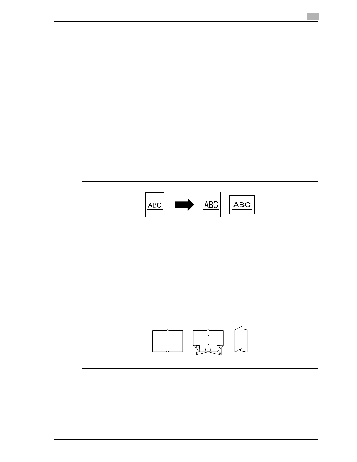
Center binding and folding in half and in three
Copies can be folded at their center ("Half-Fold" setting) or bound with staples after being folded in half
("Center Staple & Fold" setting). Otherwise, the copies can be folded in three ("Tri-fold" setting).
For details, refer to "Selecting a folding setting" on page 4-71.
Page 18
1
Introduction
1-6 CS240/CS231
Sorting copies
The finishing method for copies can be selected.
For details, refer to "Separating copies by sets ("Sort" setting)" on page 4-62, "Separating copies by pages
("Group" Setting)" on page 4-64.
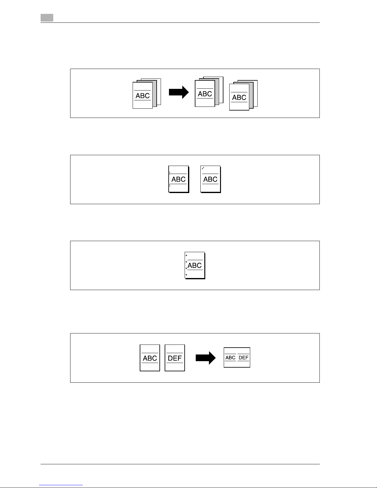
Stapling copies
Multi-page originals can be copied and stapled together.
For details, refer to "Stapling copies ("Staple" settings)" on page 4-65.
Punching holes in copies
Holes for filing can be punched in the copies.
For details, refer to "Punching holes in copies ("Punch" settings)" on page 4-69.
Copying multiple original pages onto a single page
Multiple pages of the original can be printed together on a single page.
For details, refer to "Copying multiple document pages onto a single page ("Combined Copy" settings)" on
page 4-50.
Page 19
CS240/CS231 1-7
Introduction
1
Copying an original containing various page sizes
An original with various page sizes can be scanned and copied together.
For details, refer to "Copying documents of mixed sizes ("Mixed Original" setting)" on page 4-20.
Adjusting copies according to the image quality of the original
The copies can be adjusted according to the image quality of the original.
For details, refer to "Loading documents with small print or photos ("Original Type" settings)" on page 4-52
or "Adjusting the print density ("Density" settings)" on page 4-55.
Inserting paper between copies of OHP
In order to prevent OHP from becoming stuck to each other, a page (interleaf) can be inserted between the
transparency copies.
For details, refer to "Inserting paper between OHP transparencies ("OHP Interleave" function)" on page 9-22.
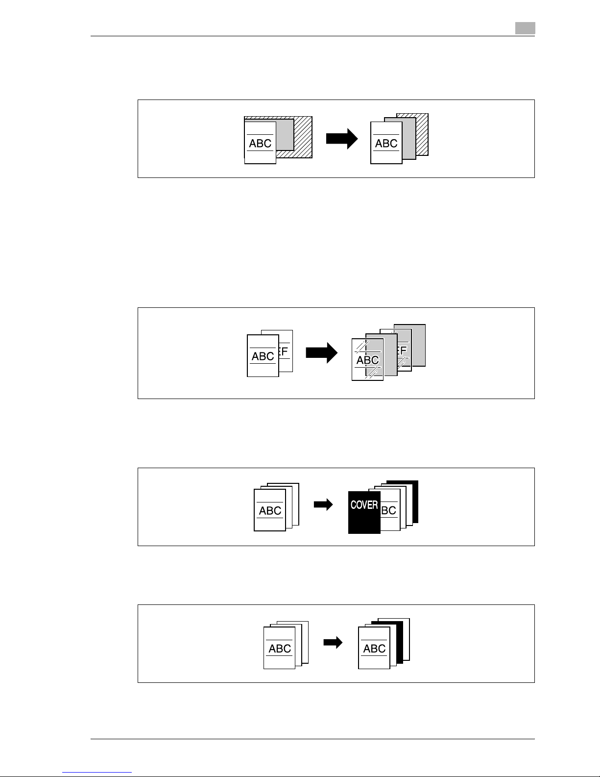
Adding a cover page
Cover pages can be added to copies, or copies can be made using different paper (for example, colored
paper) for only the cover pages.
For details, refer to "Adding cover pages ("Cover Sheet" function)" on page 9-24.
Inserting different paper into copies
Different paper (such as colored paper) can be inserted for specified pages in the copies.
For details, refer to "Inserting different paper into copies ("Insert Sheet" function)" on page 9-27.
Page 20
1
Introduction
1-8 CS240/CS231
Inserting pages from a different original at specified locations in a copy
An original scanned later can be inserted for specified pages in an original scanned earlier for copying.
For details, refer to "Inserting copies of a different document for a specified page ("Insert Image" function)"
on page 9-30.
Printing double-sided copies with the specified page on the front side
Double-sided copies can be printed with the specified pages on the front side.
For details, refer to "Specifying pages to be printed on the front side ("Chapters" function)" on page 9-33.
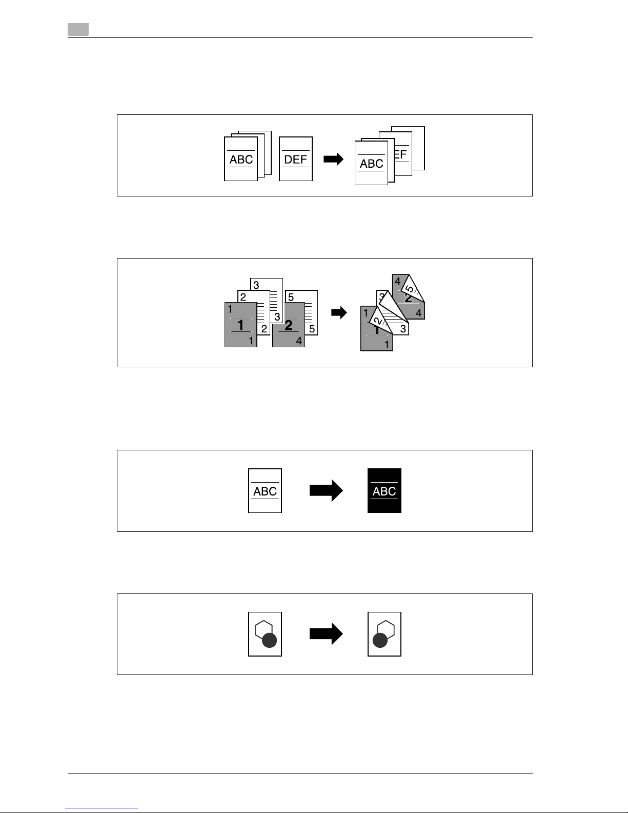
Copying with reversed colors
An original can be copied with the light- and dark-colored areas of the original image inversed. With Color
setting "Full Color", copies are printed with the hues and brightness inversed. With Color setting "Black" or
"Single Color", copies are printed with the hues inversed.
For details, refer to "Copying with image colors inversed ("Neg./Pos. Reverse" function)" on page 9-40.
Printing a mirror image
An original can be copied in its mirror image.
For details, refer to "Copying in a mirror image ("Mirror Image" function)" on page 9-42.
2
1
2
4
1
Page 21
CS240/CS231 1-9
Introduction
1
Copying with a background color
An original can be copied using one of the 18 colors available as the color of the background (blank areas).
For details, refer to "Adding a background color to copies ("Background Color" function)" on page 9-45.
Improving the copy color quality
You can adjust color copies to the quality for the desired image.
For details, refer to "Adjusting the copy color quality ("Color Adjust" parameters)" on page 9-47.
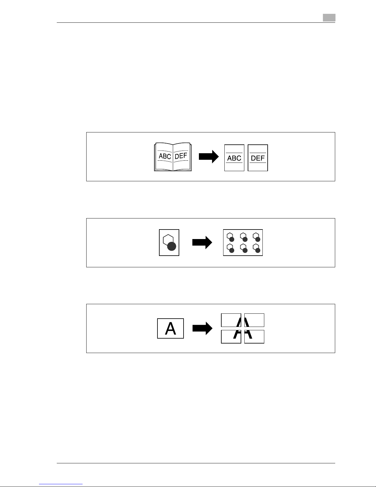
Separately copying a page spread
A page spread, such as in an open book or catalog, can be copied onto separate pages.
For details, refer to "Producing separate copies of each page in a page spread ("Book Copy" function)" on
page 9-51.
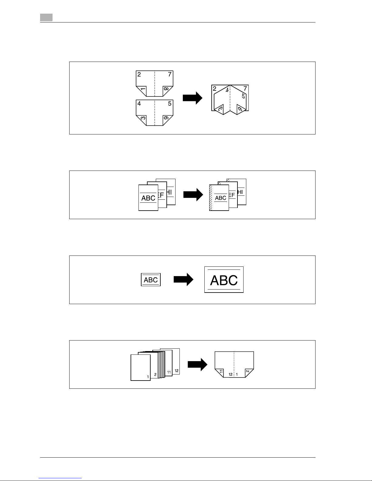
Repeating copy images
An original image can be repeatedly printed on a single sheet of paper.
For details, refer to "Tiling copy images ("Image Repeat" function)" on page 9-55.
Printing the enlarged image on multiple pages
A single original page can be automatically split into parts with each part printed enlarged.
For details, refer to "Copying an enlarged image on multiple pages ("Poster Mode" function)" on page 9-59.
Page 22
1
Introduction
1-10 CS240/CS231
Creating booklets from copies of pamphlets
Pamphlets with their staples removed can be copied and bound with staples.
For details, refer to "Copying booklets ("Booklet Original" function)" on page 9-63.
Making copies for filing
Copies can be printed with a filing margin so they can easily be stored in filing binders.
For details, refer to "Adding a binding margin to copies ("Page Margin" function)" on page 9-65.
Adjusting the image to fit the paper size
When the copy paper is larger than the original, copies can be printed so that the original image fills the paper.
For details, refer to "Adjusting the image to fit the paper ("Image Adjust" settings)" on page 9-68.
Copying with the page layout of a magazine
Copies can be made with the pages arranged in a layout for center binding, such as for a magazine.
For details, refer to "Copying with the page layout of a booklet ("Booklet" function)" on page 9-71.
Page 23
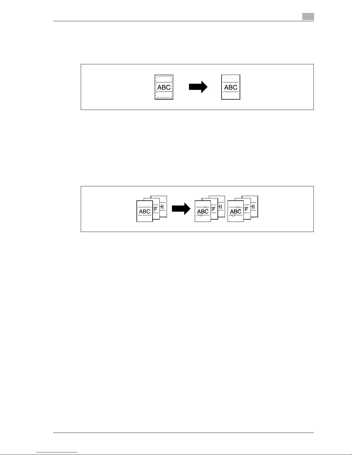
CS240/CS231 1-11
Introduction
1
Erasing sections of copies
Areas, such as the shadows of punched holes and transmission information in received faxes, can be erased
in copies.
For details, refer to "Erasing specified areas of copies ("Frame Erase" function)" on page 9-73.
Printing a sample copy
Before printing a large number of copies, a single sample copy can be printed so that it can be checked.
For details, refer to "Printing a proof to check the settings (Proof Copy)" on page 5-6.
Printing date/time or page number on copies
The date/time, page number or copy protection text (hidden text that prevents improper copying) can be
printed on copies, or each copy set can be printed with distribution numbers.
For details, refer to "Printing the date/time or page number on copies ("Stamp/Composition" functions)" on
page 9-75.
Managing jobs
The print status of copy jobs can be checked and the jobs can be managed.
For details, refer to "Managing jobs" on page 12-3.
Programming copy settings
Frequently used copy settings can be programmed and recalled to be used with other copy jobs.
For details, refer to "Registering copy programs (Mode Memory)" on page 5-9.
Checking the copy settings
Screens showing the current copy settings can be displayed. From these screens, the copy settings can also
be changed.
For details, refer to "Checking the copy settings (Check Job)" on page 5-3.
Enlarging the size of text in touch panel screens
The text and buttons in the touch panel can be displayed in a larger size that is easier to read, allowing basic
operations to be easily performed.
For details, refer to the User manual – Enlarge Display Operations.
Displaying explanations of functions and settings
The name and function of parts and details of functions and settings appears in the Help screens.
For details, refer to "Displaying function descriptions (Help)" on page 5-14.
Interrupting a copy job
The copy job being printed can be interrupted in order for a different copy job to be printed.
For details, refer to "Interrupting a copy job (Interrupt mode)" on page 5-8.
Page 24
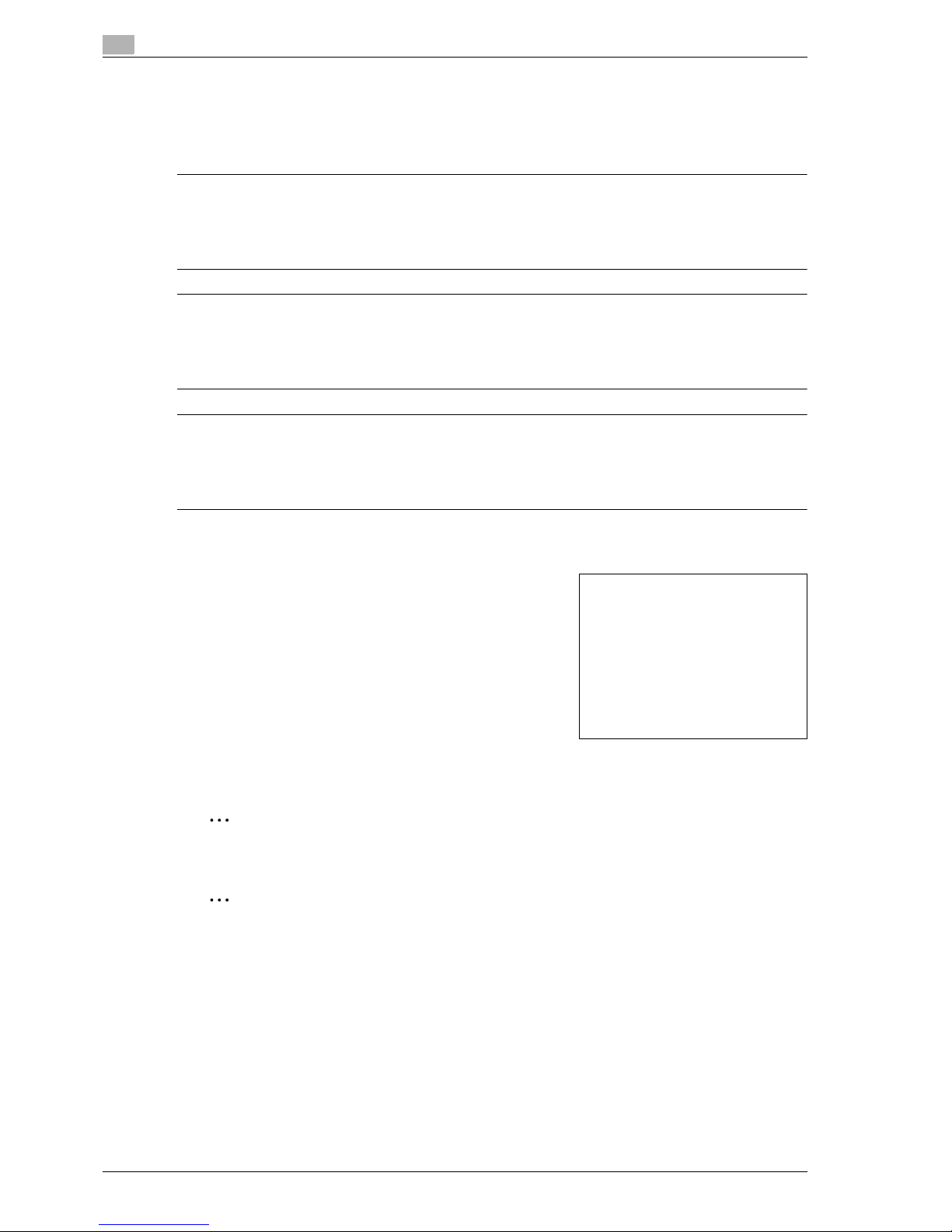
1
Introduction
1-12 CS240/CS231
1.2 Explanation of manual conventions
The marks and text formats used in this manual are described below.
Safety advices
6 DANGER
Failure to observe instructions highlighted in this manner may result in fatal or critical injuries in fact
of electrical power.
% Observe all dangers in order to prevent injuries.
7 WARNING
Failure to observe instructions highlighted in this manner may result in serious injuries or property
damage.
% Observe all warnings in order to prevent injuries and to ensure safe use of the machine.
7 CAUTION
Failure to observe instructions highlighted in this manner may result in slight injuries or property
damage.
% Observe all cautions in order to prevent injuries and to ensure safe use of the machine.
Sequence of action
1 The number 1 as formatted here indicates the first step of a
sequence of actions.
2 Subsequent numbers as formatted here indicate subsequent
steps of a sequence of actions.
?
Text formatted in this style provides additional assistance.
% Text formatted in this style describes the action that will
ensure the desired results are achieved.
Tips
2
Note
Text highlighted in this manner contains useful information and tips to ensure safe use of the machine.
2
Reminder
Text highlighted in this manner contains information that should be reminded.
!
Detail
Text highlighted in this manner contains references for more detailed information.
Special text markings
[Stop] key
The names of keys on the control panel are written as shown above.
MACHINE SETTING
Display texts are written as shown above.
An illustration inserted
here shows what operations
must be performed.
Page 25
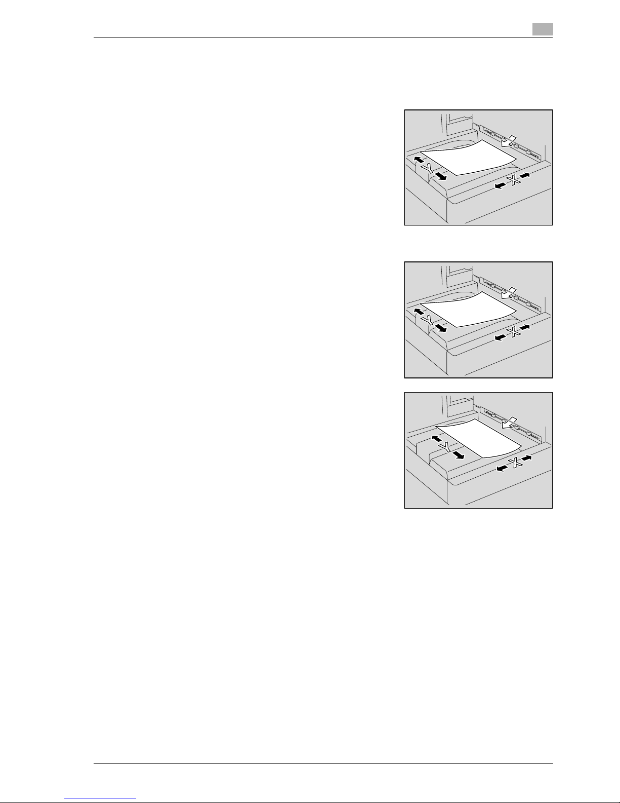
CS240/CS231 1-13
Introduction
1
1.3 Descriptions and symbols for originals and paper
The use of words and symbols in this manual are explained below.
"Width" and "Length"
Whenever paper dimensions are mentioned in this manual, the first
value always refers to the width of the paper (shown as "Y" in the
illustration) and the second to the length (shown as "X").
Paper orientation
Lengthwise (w)
If the width (Y) of the paper is shorter than the length (X), the paper
has a vertical or portrait orientation, indicated by w.
Crosswise (v)
If the width (Y) of the paper is longer than the length (X), the paper
has a horizontal or landscape orientation, indicated by v.
Page 26

1
Introduction
1-14 CS240/CS231
1.4 User manuals
This machine is provided with printed manuals and PDF manuals on the user manual CD.
User manual
This manual contains operating procedures and descriptions of the most frequently used functions.
Copy Operations (this manual)
This manual contains descriptions of the Copy mode operations and machine maintenance. Refer to this
manual for details on the paper and documents, copy procedures using convenient Application functions,
replacing consumables, and troubleshooting operations such as clearing paper misfeeds.
Print Operations
This manual contains details of the printing functions that can be specified with the standard built-in printer
controller. Refer to this manual for operating procedures on using the printing functions.
Box Operations
This manual contains operating procedures for using the user boxes on the hard disk. Refer to this manual
for details on saving data in user boxes, retrieving data from user boxes and transferring data.
Network Scanner Operations
This manual contains descriptions on specifying network settings for standard equipment and operating
procedures for scanning functions. Refer to this user manual for details on using network functions and the
Scan to E-Mail, Scan to FTP and Scan to SMB operations.
Web Connection Operations
This manual contains descriptions on the machine settings that can be specified remotely with Web
Connection from a Web browser on a computer. Refer to this manual for details on operating procedures for
using Web Connection.
Fax Operations (Option)
This manual contains descriptions of the G3 fax operations. Refer to this manual for details on using the G3
fax operations when the optional fax kit is installed.
In order to use the fax functions, the optional fax kit must be purchased separately.
Network Fax Operations (Option)
This manual contains details on the network fax functions. Refer to this manual for operating procedures on
Internet faxing and IP address faxing.
Page 27

CS240/CS231 1-15
Introduction
1
1.5 Legal restrictions on copying
Certain types of originals must never be copied with the purpose or intent to pass copies of such originals
off as the originals.
The following is not a complete list, but is meant to be used as a guide to responsible copying.
Financial Instruments
- Personal checks
- Traveler’s checks
- Money orders
- Certificates of deposit
- Bonds or other certificates of indebtedness
- Stock certificates
Legal Originals
- Food stamps
- Postage stamps (canceled or uncanceled)
- Checks or drafts drawn by government agencies
- Internal revenue stamps (canceled or uncanceled)
- Passports
- Immigration papers
- Motor vehicle licenses and titles
- House and property titles and deeds
General
- Identification cards, badges, or insignias
- Copyrighted works without permission of the copyright owner
In addition,
it is prohibited under any circumstances
to copy domestic or foreign currencies, or works of
art without permission of the copyright owner.
When in doubt about the nature of an original, consult with legal counsel.
!
Detail
In order to prohibit the illegal reproduction of certain originals, such as paper currency, this machine is
equipped with a counterfeit prevention feature.
Due to the counterfeit prevention feature that this machine is equipped with, images may be distorted.
Page 28

1
Introduction
1-16 CS240/CS231
Page 29

2
Installation and operation
precautions
Page 30

Page 31

CS240/CS231 2-3
Installation and operation precautions
2
2 Installation and operation precautions
2.1 Safety information
This section contains detailed instructions on the operation and maintenance of this machine. To achieve
optimum utility of this device, all operators should carefully read and follow the instructions in this manual.
Please read the following section before connecting the machine to the supply. It contains important
information related to user safety and preventing equipment problems.
Please keep this manual in a handy place near the machine.
Make sure you observe all of the precautions appear in each section of this manual.
KM_Ver.01E_C
2
Note
Some parts of the contents of this section may not correspond with the purchased product.
Warning and precaution symbols
The following indicators are used on the warning labels or in this manual to categorize the level of safety
warnings.
7 WARNING
Ignoring this warnings could cause serious injury or even death.
% Do not ignore this safety advices.
7 CAUTION
Ignoring this cautions could cause injury or damage to property.
% Do not ignore this safety advices.
Meaning of symbols
Symbol Meaning Example Meaning
A triangle indicates a danger against
which you should take precaution.
This symbol warns against possible
causes of burns.
A diagonal line indicates a prohibited
course of action.
This symbol warns against dismantling
the device.
A black circle indicates an imperative
course of action.
This symbol indicates you must unplug
the device.
Page 32

2
Installation and operation precautions
2-4 CS240/CS231
Disassemble and modification
7 WARNING
Ignoring this warnings could cause serious injury or even death.
% Do not ignore this safety advices.
Power cord
7 WARNING
Ignoring this warnings could cause serious injury or even death.
% Do not ignore this safety advices.
Warning Symbol
• Do not attempt to remove the covers and panels which have been fixed to the product.
Some products have a high-voltage part or a laser beam source inside that could
cause an electrical shock or blindness.
• Do not modify this product, as a fire, electrical shock, or breakdown could result. If the
product employs a laser, the laser beam source could cause blindness.
Warning Symbol
• Use only the power cord supplied in the package. If a power cord is not supplied, only
use the power cord and plug that is specified in POWER CORD INSTRUCTION. Failure
to use this cord could result in a fire or electrical shock.
• Use the power cord supplied in the package only for this machine and NEVER use it
for any other product. Failure to observe this precaution could result in a fire or electrical shock.
• Do not scratch, abrade, place a heavy object on, heat, twist, bend, pull on, or damage
the power cord. Use of a damaged power cord (exposed core wire, broken wire, etc.)
could result in a fire or breakdown.
Should any of these conditions be found, immediately turn OFF the power switch, unplug the power cord from the power outlet, and then call your authorized service representative.
Page 33

CS240/CS231 2-5
Installation and operation precautions
2
Power source
7 WARNING
Ignoring this warnings could cause serious injury or even death.
% Do not ignore this safety advices.
7 CAUTION
Ignoring this cautions could cause injury or damage to property.
% Do not ignore this safety advices.
Power plug
7 WARNING
Ignoring this warnings could cause serious injury or even death.
% Do not ignore this safety advices.
Warning Symbol
• Use only the specified power source voltage. Failure to do that could result in a fire or
electrical shock.
• Connect power plug directly into wall outlet having the same configuration as the plug.
Use of an adapter leads to the product connecting to inadequate power supply (voltage, current capacity, grounding), and may result in fire or shock. If proper wall outlet
is not available, the customer shall ask qualified electrician for the installation.
• Do not use a multiple outlet adapter nor an extension cord in principle. Use of an
adapter or an extension cord could cause a fire or electrical shock.
Contact your authorized service representative if an extension cord is required.
• Consult your authorized service representative before connecting other equipment on
the same wall outlet. Overload could result in a fire.
Caution Symbol
• The outlet must be near the equipment and easily accessible. Otherwise you can not
pull out the power plug when an emergency occurs.
Warning Symbol
• Do not unplug and plug in the power cord with a wet hand, as an electrical shock could
result.
• Plug the power cord all the way into the power outlet. Failure to do this could result in
a fire or electrical shock.
Page 34

2
Installation and operation precautions
2-6 CS240/CS231
7 CAUTION
Ignoring this cautions could cause injury or damage to property.
% Do not ignore this safety advices.
Grounding
7 WARNING
Ignoring this warnings could cause serious injury or even death.
% Do not ignore this safety advices.
Installation
7 WARNING
Ignoring this warnings could cause serious injury or even death.
% Do not ignore this safety advices.
Caution Symbol
• Do not tug the power cord when unplugging. Pulling on the power cord could damage
the cord, resulting in a fire or electrical shock.
• Remove the power plug from the outlet more than one time a year and clean the area
between the plug terminals. Dust that accumulates between the plug terminals may
cause a fire.
Warning Symbol
• Connect the power cord to an electrical outlet that is equipped with a grounding terminal.
Warning Symbol
• Do not place a flower vase or other container that contains water, or metal clips or other small metallic objects on this product. Spilled water or metallic objects dropped inside the product could result in a fire, electrical shock, or breakdown.
Should a piece of metal, water, or any other similar foreign matter get inside the product, immediately turn OFF the power switch, unplug the power cord from the power
outlet, and then call your authorized service representative.
Page 35

CS240/CS231 2-7
Installation and operation precautions
2
7 CAUTION
Ignoring this cautions could cause injury or damage to property.
% Do not ignore this safety advices.
Ventilation
7 CAUTION
Ignoring this cautions could cause injury or damage to property.
% Do not ignore this safety advices.
Actions in response to troubles
7 WARNING
Ignoring this warnings could cause serious injury or even death.
% Do not ignore this safety advices.
Caution Symbol
• After installing this product, mount it on a secure base. If the unit moves or falls, it may
cause personal injury.
• Do not place the product in a dusty place, or a site exposed to soot or steam, near a
kitchen table, bath, or a humidifier. A fire, electrical shock, or breakdown could result.
• Do not place this product on an unstable or tilted bench, or in a location subject to a
lot of vibration and shock. It could drop or fall, causing personal injury or mechanical
breakdown.
• Do not let any object plug the ventilation holes of this product. Heat could accumulate
inside the product, resulting in a fire or malfunction.
• Do not use flammable sprays, liquids, or gases near this product, as a fire could result.
Caution Symbol
• Always use this product in a well ventilated location. Operating the product in a poorly
ventilated room for an extended period of time could injure your health. Ventilate the
room at regular intervals.
Warning Symbol
• Do not keep using this product, if this product becomes inordinately hot or emits
smoke, or unusual odor or noise. Immediately turn OFF the power switch, unplug the
power cord from the power outlet, and then call your authorized service representative.
If you keep on using it as is, a fire or electrical shock could result.
• Do not keep using this product, if this product has been dropped or its cover damaged.
Immediately turn OFF the power switch, unplug the power cord from the power outlet,
and then call your authorized service representative. If you keep on using it as is, a fire
or electrical shock could result.
Page 36

2
Installation and operation precautions
2-8 CS240/CS231
7 CAUTION
Ignoring this cautions could cause injury or damage to property.
% Do not ignore this safety advices.
Consumables
7 WARNING
Ignoring this warnings could cause serious injury or even death.
% Do not ignore this safety advices.
7 CAUTION
Ignoring this cautions could cause injury or damage to property.
% Do not ignore this safety advices.
When moving the machine
7 CAUTION
Ignoring this cautions could cause injury or damage to property.
% Do not ignore this safety advices.
Caution Symbol
• The inside of this product has areas subject to high temperature, which may cause
burns.
When checking the inside of the unit for malfunctions such as a paper misfeed, do not
touch the locations (around the fusing unit, etc.) which are indicated by a "Caution
HOT" caution label.
Warning Symbol
• Do not throw the toner cartridge or toner into an open flame. The hot toner may scatter
and cause burns or other damage.
Caution Symbol
• Do not leave a toner unit or drum unit in a place within easy reach of children. Licking
or ingesting any of these things could injure your health.
• Do not store toner units and PC drum units near a floppy disk or watch that are susceptible to magnetism. They could cause these products to malfunction.
Caution Symbol
• Whenever moving this product, be sure to disconnect the power cord and other cables. Failure to do this could damage the cord or cable, resulting in a fire, electrical
shock, or breakdown.
• When moving this product, always hold it by the locations specified in the user manual
or other documents. If the unit falls it may cause severe personal injury. The product
may also be damaged or malfunction.
Page 37

CS240/CS231 2-9
Installation and operation precautions
2
Before successive holidays
When the optional Fax Kit FK-502 is not installed:
7 CAUTION
Ignoring this cautions could cause injury or damage to property.
% Do not ignore this safety advices.
Caution Symbol
• Unplug the product when you will not use the product for long periods of time.
Page 38

2
Installation and operation precautions
2-10 CS240/CS231
2.2 Regulation notices
CE Marking (Declaration of Conformity) for users of the European Union (EU)
This product complies with the following EU directives:
89/336/EEC, 73/23/EEC and 93/68/EEC directives.
This declaration is valid for the area of the European Union.
This device must be used with a shielded network (10 Base-T/100 Base-TX) cable and a shielded parallel
cable. The use of non-shielded cables is likely to result in interference with radio communications and is
prohibited under CISPR rules and local rules.
User Instructions FCC Part 15 - Radio Frequency Devices (for U.S.A. users)
This equipment has been tested and found to comply with the limits for a Class A digital device, pursuant to
Part 15 of the FCC Rules.
These limits are designed to provide reasonable protection against harmful interference when the equipment
is operated in a commercial environment. This equipment generates, uses and can radiate radio frequency
energy and, if not installed and used in accordance with the instruction manual, may cause harmful
interference to radio communications. Operation of this equipment in a residential area is likely to cause
harmful interference in which case the user will be required to correct the interference at his own expense.
7 WARNING
The design and production of this unit conform to FCC regulations, and any changes or modifications
must be registered with the FCC and are subject to FCC control.
Any changes made by the purchaser or user without first contacting the manufacturer will be subject to
penalty under FCC regulations.
% This device must be used with a shielded network (10 Base-T/100 Base-TX) cable and a shielded
parallel cable. The use of non-shielded cables is likely to result in interference with radio
communications and is prohibited under FCC rules.
Interference-Causing Equipment Standard (ICES-003 ISSUE 4) (for Canada users)
This Class A digital apparatus complies with Canadian ICES-003.
Cet appareil numérique de la classe A est conforme à la norme NMB-003 du Canada.
For users in countries not subject to class B regulations
7 WARNING
Interference with radio communications:
% This is a Class A product. In a domestic environment this product may cause radio interference in which
case the user may be required to take adequate measures.
% This device must be used with a shielded network (10 Base-T/100 Base-TX) cable and a shielded
parallel cable. The use of non-shielded cables is likely to result in interference with radio
communications and is prohibited under CISPR rules and local rules.
Page 39

CS240/CS231 2-11
Installation and operation precautions
2
Laser safety
This is a digital machine which operates using a laser. There is no possibility of danger from the laser provided
the machine is operated according to the instructions in this manual.
Since radiation emitted by the laser is completely confined within protective housing, the laser beam cannot
escape from the machine during any phase of user operation.
This machine is certified as a Class 1 laser product: This means the machine does not produce hazardous
laser radiation.
Internal laser radiation
7 WARNING
This product employs a Class 3B laser diode that emits an invisible laser beam.
% The laser diode and the scanning polygon mirror are incorporated in the print head unit.
% The print head unit is NOT A FIELD SERVICE ITEM:
Therefore, the print head unit should not be opened under any circumstances.
Specification
Maximum average radiation pow-er12.9 µW at the laser aperture of the print head unit
Wavelength 775-800 nm
Laser Aperture of the
Print Head Unit
Print Head
Page 40

2
Installation and operation precautions
2-12 CS240/CS231
CDRH regulations
This machine is certified as a Class 1 Laser product under Radiation Performance Standard according to the
Food, Drug and Cosmetic Act of 1990. Compliance is mandatory for Laser products marketed in the United
States and is reported to the Center for Devices and Radiological Health (CDRH) of the U.S. Food and Drug
Administration of the U.S. Department of Health and Human Services (DHHS). This means that the device
does not produce hazardous laser radiation.
The label shown on page 2-11 indicates compliance with the CDRH regulations and must be attached to
laser products marketed in the United States.
7 CAUTION
Use of controls, adjustments or performance of procedures other than those specified in this manual
may result in hazardous radiation exposure.
% This is a semiconductor laser. The maximum power of the laser diode is 30 mW and the wavelength is
775-800 nm.
For European users
7 CAUTION
Use of controls, adjustments or performance of procedures other than those specified in this manual
may result in hazardous radiation exposure.
% This is a semiconductor laser. The maximum power of the laser diode is 30 mW and the wavelength is
775-800 nm.
For Denmark users
7 ADVARSEL
Dette er en halvlederlaser.
% Usynlig laserstråling ved åbning, når sikkerhedsafbrydere er ude af funktion. Undgå udsættelse for
stråling. Klasse 1 laser produkt der opfylder IEC 60825 sikkerheds kravene.
Dette er en halvlederlaser. Laserdiodens højeste styrke er 30 mW og bølgelængden er 775-800 nm.
For Finland, Sweden users
LOUKAN 1 LASERLAITE
KLASS 1 LASER APPARAT
7 VAROITUS
Tämä on puolijohdelaser.
% Laitteen Käyttäminen muulla kuin tässä käyttöohjeessa mainitulla tavalla saattaa altistaa käyttäjän
turvallisuusluokan 1 ylittävälle näkymättömälle lasersäteilylle.
Tämä on puolijohdelaser. Laserdiodin sunrin teho on 30 mW ja aallonpituus on 775-800 nm.
7 VARNING
Det här är en halvledarlaser.
% Om apparaten används på annat sätt än i denna bruksanvisning specificerats, kan användaren utsättas
för osynlig laserstrålning, som överskrider gränsen för laserklass 1.
Det här är en halvledarlaser. Den maximala effekten för laserdioden är 30 mW och våglängden är 775-800 nm.
Page 41

CS240/CS231 2-13
Installation and operation precautions
2
7 VAROITUS
Avattaessa ja suojalukitus ohitettaessa olet alttiina näkymättömälle lasersäteilylle.
% Älä katso säteeseen.
7 VARNING
Osynlig laserstrålning när denna del är öppnad och spärren är urkopplad.
% Betrakta ej strålen.
For Norway users
7 ADVARSEL!
Dette en halvleder laser.
% Dersom apparatet brukes på annen måte enn spesifisert i denne bruksanvisning, kan brukeren utsettes
for unsynlig laserstråling som overskrider grensen for laser klass 1.
Dette en halvleder laser. Maksimal effekt till laserdiode er 30 mW og bølgelengde er 775-800 nm.
Laser safety label
A laser safety label is attached to the outside of the machine, as shown below.
* Only for the U.S.A.
Page 42

2
Installation and operation precautions
2-14 CS240/CS231
Ozone release
7 CAUTION
Locate the machine in a well ventilated room
% A negligible amount of ozone is generated during normal operation of this machine. An unpleasant odor
may, however, be created in poorly ventilated rooms during extensive machine operations. For a
comfortable, healthy, and safe operating environment, it is recommended that the room well ventilated.
7 ATTENTION
Placer l’appareil dans une pièce largement ventilée.
% Une quantité d’ozone négligable est dégagée pendant le fonctionnement de l’appareil quand celui-ci
est utilisé normalement. Cependant, une odeur désagréable peut être ressentie dans les pièces dont
l’aération est insuffisante et lorsque une utilisation prolongée de l’appareil est effectuée. Pour avoir la
certitude de travailler dans un environnement réunissant des conditions de confort, santé et de sécurité,
il est préférable de bien aérer la pièce ou se trouve l’appareil.
Acoustic noise (for European users only)
Maschinenlärminformations-Verordnung 3. GPSGV: Der höchste Schalldruckpegel beträgt 70 dB(A) oder
weniger gemäß EN ISO 7779.
For EU member states only
This symbol means: Do not dispose of this product together with
your household waste!
Please refer to the information of your local community or contact
our dealers regrading the proper handling of end-of-life electric and
electronic equipments. Recycling of this product will help to
conserve natural resources and prevent potential negative
consequences for the environment and human health caused by
inappropriate waste handling.
This product complies with RoHS (2002/95/EC) Directive.
This device is not intended for use at a video workstation in compliance with BildscharbV.
Das Gerat ist nicht fur die Benutzung am Bildschirmarbeitsplatz gemäß BildscharbV vorgesehen.
Page 43

CS240/CS231 2-15
Installation and operation precautions
2
2.3 Caution notations and labels
Safety precaution notations and labels appear on this machine at the following positions.
Be very careful that an accident does not occur when operations such as removing paper misfeeds are
performed.
Page 44

2
Installation and operation precautions
2-16 CS240/CS231
2.4 Space requirements
To ensure that machine operation, consumables replenishing, part replacement, and regular maintenance
can easily be performed, adhere to the recommended space requirements detailed below.
2
Reminder
Be sure to allow a clearance of 100 mm (4 in.) or more at the back of this machine for the ventilation
duct.
Unit: mmCS240/CS231+FS-608+LU-301
806.5 958.3 387 391.9 1130 50
1155 494
CS231+FS-519+SD-505+LU-301 Unit: mm
555 958.3 387 391.9 1130 50
1155 494
190.6
Page 45

CS240/CS231 2-17
Installation and operation precautions
2
2.5 Operation precautions
To ensure the optimum performance of this machine, observe the precautions described below.
Power source
The power source requirements are as follows.
- Voltage fluctuation: Maximum ± 10% (at 220 to 240 V AC)
- Frequency fluctuation: Maximum ± 3 Hz (at 50 Hz)
– Use a power source with as little voltage or frequency fluctuations as possible.
Operating environment
The environmental requirements for correct operation of the machine are as follows.
- Temperature: 10°C (50°F) to 30°C (86°F) with fluctuations of no more than 10°C (18°F) within an hour
- Humidity: 15% to 85% with fluctuations of no more than 20% within an hour
Storage of copies
To store copies, follow the recommendation listed below.
- Copies that are to be kept for a long time should be kept where they are not exposed to light in order
to prevent them from fading.
- Adhesive that contains solvent (e.g., spray glue) may dissolve the toner on copies.
- Color copies have a thicker layer of toner than normal black-and-white copies. Therefore, when a color
copy is folded, the toner at the fold may peel off.
Page 46

2
Installation and operation precautions
2-18 CS240/CS231
Page 47

3
Before making copies
Page 48

Page 49

CS240/CS231 3-3
Before making copies
3
3 Before making copies
3.1 Part names and their functions
Options
CS240
89
10
2
1
3
4
5
98
6
7
No. Part name Description
1 Main unit The document is scanned by the scanner section, and the
scanned image is printed by the printer section.
Referred to as the "machine", the "main unit", or the "CS240"
throughout the manual.
2 Authentication unit (biometric type) AU-
101
Performs user authentication by scanning vein patterns in the finger.
For details, refer to the manual provided with the authentication
unit (biometric type).
3 Working table WT-502 Provides an area to temporarily place a document or other mate-
rials. This is also used when the authentication unit (biometric
type) is installed.
4 Fax multi line ML-501 Installed to increase the telephone lines available for faxing.
5 Large capacity unit LU-301 Can be loaded with up to 3,000 sheets of plain A4-size paper.
Can be loaded with the following A4-size paper: 2,500 sheets of
thick paper 1, 1,750 sheets of thick paper 1+, 1,CS240 sheets of
thick paper 2 or 1,300 sheets of thick paper 3.
Referred to as the "LCT" throughout the manual.
6 Finisher FS-517 Feeds out finished printed pages. The "Sort" setting (separating
by copy set), "Group" setting (separating by page), and Staple
settings ("Corner" and "2 Positions") are available.
7 Finisher FS-608 Feeds out finished printed pages. The "Sort" setting (separating
by copy set), "Group" setting (separating by page), Staple settings ("Corner" and "2 Position"), "Half-Fold", "Center Staple &
Fold", and "Tri-Fold" are available.
8 Punch kit PK-512 Installed onto the finisher to allow hole punching to be used.
9 Punch kit PK-513 Installed onto the finisher to allow hole punching to be used.
Page 50

3
Before making copies
3-4 CS240/CS231
* Parts marked with an asterisk are internal options and therefore are not shown in the illustration.
CS240
10 Output tray OT-503 Collects printed pages.
11 Fax kit FK-502* Allows this machine to be used as a fax machine.
12 Stamp unit SP-501* Applies a stamp to documents that have been scanned.
For details, refer to the User manual – Fax Operations (Option).
13 Scan accelerator kit SA-501* Creates images at high speed when sending scans.
14 Security kit SC-503* Installed to encode the data saved on the hard disk so that the
hard disk can be used more safely.
15 Local interface kit EK-602* Used for connecting the authentication unit (biometric type) and
the JScribe IC card reader/writer.
No. Part name Description
13
11
14
10
8
2
3
4
5
9
6
8
12
9
7
15
1
Page 51

CS240/CS231 3-5
Before making copies
3
* Parts marked with an asterisk are internal options and therefore are not shown in the illustration.
No. Part name Description
1 Main unit The document is scanned by the scanner section, and the
scanned image is printed by the printer section.
Referred to as the "machine", the "main unit", or the "CS231"
throughout the manual.
2 Authentication unit (biometric type)
AU-101
Performs user authentication by scanning vein patterns in the finger.
For details, refer to the manual provided with the authentication
unit (biometric type).
3 Working table WT-502 Provides an area to temporarily place a document or other mate-
rials. This is also used when the authentication unit (biometric
type) is installed.
4 Fax multi line ML-501 Installed to increase the telephone lines available for faxing.
5 Large capacity unit LU-301 Can be loaded with up to 3,000 sheets of plain A4-size paper.
Can be loaded with the following A4-size paper: 2,500 sheets of
thick paper 1, 1,750 sheets of thick paper 1+, 1,CS240 sheets of
thick paper 2 or 1,300 sheets of thick paper 3.
Referred to as the "LCT" throughout the manual.
6 Finisher FS-517 Feeds out finished printed pages. The "Sort" setting (separating
by copy set), "Group" setting (separating by page), and Staple
settings ("Corner" and "2 Positions") are available.
7 Finisher FS-608 Feeds out finished printed pages. The "Sort" setting (separating
by copy set), "Group" setting (separating by page), Staple settings ("Corner" and "2 Position"), "Half-Fold", "Center Staple &
Fold", and "Tri-Fold" are available.
8 Punch kit PK-512 Installed onto the Finisher FS-517/FS-608 to allow hole punching
to be used.
9 Punch kit PK-513 Installed onto the Finisher FS-517/FS-608 to allow hole punching
to be used.
10 Finisher FS-519 Feeds out finished printed pages. The "Sort" setting (separating
by copy set), "Group" setting (separating by pages) and Staple
settings ("Corner" and "2 Position") are available.
11 Output tray OT-602 Installed onto finisher FS-519 and used for separating printed
pages.
Referred to as the "optional output tray" throughout the manual.
12 Mailbin kit MT-502 Installed onto finisher FS-519 to divide printed pages (only with
computer printing) and feed them into the appropriate tray assigned to a specific individual or group.
Referred to as the "mailbin" throughout the manual.
13 Saddle stitcher SD-505 Installed onto finisher FS-519 so that copies can be bound or
folded at the center.
Referred to as the "saddle stitcher" throughout the manual.
14 Punch kit PK-510 Installed onto finisher FS-519 to allow hole punching to be used.
15 Output tray OT-503 Collects printed pages.
16 Fax kit FK-502* Allows this machine to be used as a fax machine.
17 Stamp unit SP-501* Applies a stamp to documents that have been scanned.
For details, refer to the User manual – Fax Operations (Option).
18 Scan accelerator kit SA-501* Creates images at high speed when sending scans.
19 Security kit SC-503* Installed to encode the data saved on the hard disk so that the
hard disk can be used more safely.
20 Local interface kit EK-602* Used for connecting the authentication unit (biometric type) and
the JScribe IC card reader/writer.
Page 52

3
Before making copies
3-6 CS240/CS231
Outside of machine
*The illustration above shows the main unit with the optional output tray installed.
2
3
4
5
6
7
8
9
10
11
12 1
No. Part name Description
1 ADF Automatically feeds in and scans one document page at a time.
Double-sided document pages can also be scanned.
2 Automatic duplex unit Turns over the paper for double-sided printing.
3 Bypass tray Used when printing onto paper with a size not loaded into a pa-
per tray or onto thick paper, OHP transparencies, postcards, envelopes or label sheets.
Can be loaded with up to 150 sheets of plain paper, 100 sheets
of thick paper 1, 80 sheets of thick paper 1+, 70 sheets of thick
paper 2, 60 sheets of thick paper 3, 50 sheets of thick paper 4,
20 OHP transparencies, 50 postcards or label sheets, or 10 envelopes.
4 Paper-empty indicator Flashes in orange when very few pages remain in the paper tray,
and lights up when the tray is empty.
5 Tray 4 Can be loaded with up to 1,000 sheets of plain paper.
Can be loaded with up to 750 sheets of thick paper 1, 500 sheets
of thick paper 1+, 450 sheets of thick paper 2, 400 sheets of thick
paper 3, or 200 postcards.
6 Tray 3 Can be loaded with up to 1,500 sheets of plain paper.
Can be loaded with up to 1,150 sheets of thick paper 1, 800
sheets of thick paper 1+, 700 sheets of thick paper 2, 600 sheets
of thick paper 3, or 200 postcards.
7 Tray 2 Can be loaded with up to 500 sheets of plain paper.
Can be loaded with up to 400 sheets of thick paper 1, 280 sheets
of thick paper 1+, 250 sheets of thick paper 2, or 200 sheets of
thick paper 3.
8 Tray 1 Can be loaded with up to 500 sheets of plain paper.
Can be loaded with up to 400 sheets of thick paper 1, 280 sheets
of thick paper 1+, 250 sheets of thick paper 2, or 200 sheets of
thick paper 3.
Page 53

CS240/CS231 3-7
Before making copies
3
9 Lower front door Opened when replacing the waste toner box and when replacing
the imaging unit, when cleaning the print head.
10 Upper front door Opened when replacing the toner cartridge.
11 Output tray Collects printed pages.
12 Control panel Used to specify the various machine settings.
No. Part name Description
Page 54

3
Before making copies
3-8 CS240/CS231
*The illustration above shows the main unit with the optional output tray installed.
17
18
19
20
21
22
23
24
25
26
1413 15 16
No. Part name Description
13 Left-side cover Opened when clearing paper misfeeds.
14 Lateral guide Adjusted to the width of the document.
15 Document feed tray Loaded with documents facing up.
16 Document output tray Collects documents that have been scanned. Open the output
tray when clearing a misfeed in the ADF.
17 [Power] (auxiliary power) key Pressed to turn on/off machine operations.
When turned off, the machine enters a state where it conserves
energy.
18 Automatic duplex unit release lever Used to open the automatic duplex unit door when clearing pa-
per misfeeds.
19 Upper right-side door release lever Used to open the upper right-side door.
20 Bypass tray door Opened when clearing paper misfeeds.
21 Bypass tray door release lever Used to open the bypass tray door when clearing paper mis-
feeds.
22 Lower right-side door Opened when clearing paper misfeeds from the paper transport
section of tray 2, 3 or 4.
23 Lower right-side door release lever Used to open the Lower right-side door.
24 Total counter Shows the total number of pages that have been printed.
25 Main power switch Used to turn the machine on and off.
26 Status indicator The machine’s current status is indicated by the color and light-
ing/flashing of the indicator.
Flashing in blue: Printing normally
Flashing in orange: Warning
Lit in orange: Stopping operating
Page 55

CS240/CS231 3-9
Before making copies
3
*The illustration above shows the main unit with the optional fax multi line, fax kit, and local interface kit
installed.
27
28
29
42
30
31
32
333435
37
38
39
40
41
36
No. Part name Description
27 ADF connector Used for connecting the ADF hookup cord.
28 Finisher connector Used for connecting the finisher hookup cord.
29 Filter Collects the toner dust generated in the machine.
30 Power cord Supplies power to the machine.
31 Jack for connecting a telephone
(TEL PORT2)
Used for connecting the cord from a telephone.
32 Telephone jack 2
(LINE PORT2)
Used for connecting a general subscriber line.
This jack is used when the optional fax multi line is installed.
33 Jack for connecting a telephone
(TEL PORT1)
Used for connecting the cord from a telephone.
34 Telephone jack 1
(LINE PORT1)
Used for connecting a general subscriber line.
35 RS-232C port Used for connecting the JScribe IC card reader/writer.
36 USB port Used for connecting the USB cable for the authentication unit
(biometric type).
37 External controller port Used for connecting the cable from an external controller.
38 Internal controller port Used for connecting the internal controller.
39 USB port (type B)
USB 2.0/1.1-compliant
Used for making connections when the machine is used as a
USB printer.
40 RS-232 port Used for connecting the modem for CS Remote Care.
Page 56

3
Before making copies
3-10 CS240/CS231
41 Network connector
(10Base-T/100Base-TX/1000Base-T)
Used for connecting the network cable when this machine is
used for network printing and network scanning.
42 Ozone filter Collects the ozone generated in the machine.
No. Part name Description
Page 57

CS240/CS231 3-11
Before making copies
3
Inside of machine
1
2
3
4
13
9
87
11
12
10
6
5
No. Part name Description
1 Original glass The document placed on the glass is scanned.
2 Fusing unit cover Opened when clearing paper misfeeds in the fusing unit.
3 Fusing unit cover lever Used to open the fusing unit cover.
4 Upper right-side door Opened when clearing paper misfeeds from inside the main unit.
5 Print head glass cleaning tool Used to clean the surface of the print head glass, for example,
when replacing the imaging unit.
6 Waste toner box Collects used waste toner.
7 Imaging unit Creates the print image.
8 Charger-cleaning tool Used to clean the electrostatic charger wire, for example, when
incorrect copies are produced.
9 Imaging unit release lever Used when removing an imaging unit.
10 Toner cartridges There are four toner cartridges: cyan (C), magenta (M), yellow (Y)
and black (K). The combination of the four toners generates fullcolor images.
11 Left partition glass Used to scan the document image in this area when the ADF is
used.
Page 58

3
Before making copies
3-12 CS240/CS231
12 Document scales Position the document so that it is aligned with the scales. Also,
use the scales to measure the loaded document.
13 Misfeed-clearing dial Turned when clearing paper misfeeds within the ADF.
No. Part name Description
Page 59

CS240/CS231 3-13
Before making copies
3
Finisher FS-517/Punch kit PK-512/Punch kit PK-513
Finisher FS-517
7
8
15
9
13
10
12
11
123 4145 6
No. Part name Description
1 Front door Opened when clearing paper misfeeds or jammed staples or
when replacing the staple cartridge.
2 Finishing tray 1 Collects printed pages.
3 Finishing tray 2 Collects printed pages.
4 Guide lever FN4 Opened when clearing paper misfeeds.
5 Guide lever FN1 Opened when clearing paper misfeeds.
6 Horizontal transport unit cover Opened when clearing paper misfeeds within the horizontal
transport unit.
7 Misfeed-clearing dial FN3 Turned when clearing paper misfeeds within the finisher.
8 Guide lever FN2 Opened when clearing paper misfeeds.
9 Stacker unit Removed when clearing paper misfeeds or jammed staples or
when replacing the staple cartridge.
10 Staple cartridge holder Removed from the stacker unit when clearing jammed staples or
when replacing the staple cartridge.
11 Handle FN7 Grabbed when removing and inserting the stacker unit.
12 Misfeed-clearing dial FN6 Turned when clearing paper misfeeds within the finisher.
13 Guide lever FN5 Opened when clearing paper misfeeds.
Page 60

3
Before making copies
3-14 CS240/CS231
Punch kit PK-512/Punch kit PK-513
Finisher FS-608/Punch kit PK-512/Punch kit PK-513
No. Part name Description
14 Punch kit Punches holes for filing printed pages when the punch kit is in-
stalled onto Finisher FS-517.
15 Punch scrap box Removed when emptying punch scraps that have accumulated
from using the Punch settings.
56
18
7
8
19
11
12
13
14
10
9
15
12 3 4
Page 61

CS240/CS231 3-15
Before making copies
3
Finisher FS-608
17
16
No. Part name Description
1 Finishing tray 1 Collects printed pages.
2 Finishing tray 2 Collects printed pages.
3 Front door Opened when clearing paper misfeeds or jammed staples or
when replacing the staple cartridge.
4 Horizontal transport unit cover Opened when clearing paper misfeeds within the horizontal
transport unit.
5 Guide lever FN4 Opened when clearing paper misfeeds.
6 Guide lever FN1 Opened when clearing paper misfeeds.
7 Misfeed-clearing dial FN3 Turned when clearing paper misfeeds within the finisher.
8 Guide lever FN2 Opened when clearing paper misfeeds.
9 Guide lever FN5 Opened when clearing paper misfeeds.
10 Guide lever FN9 Opened when clearing paper misfeeds.
11 Stacker unit Pulled out when clearing paper misfeeds or jammed staples or
when replacing the staple cartridge.
12 Guide lever FN8 Opened when clearing paper misfeeds.
13 Misfeed-clearing dial FN7 Turned when clearing paper misfeeds within the finisher.
Page 62

3
Before making copies
3-16 CS240/CS231
Punch kit PK-512/Punch kit PK-513
Finisher FS-519/Output tray OT-602/Punch kit PK-510 (CS240)
14 Handle FN6 Grabbed when removing and inserting the stacker unit.
15 Finishing tray 3 Collects copies printed using a setting.
16 Guide lever FN10 Opened when clearing paper misfeeds.
17 Staple cartridge holder Removed from the stacker unit when clearing jammed staples or
when replacing the staple cartridge.
No. Part name Description
No. Part name Description
18 Punch kit Punches holes for filing printed pages when the punch kit is in-
stalled onto Finisher FS-608.
19 Punch scrap box Removed when emptying punch scraps that have accumulated
from using the Punch settings.
1
14
2
34 5 6 7
8910111213
Page 63

CS240/CS231 3-17
Before making copies
3
Finisher FS-519
Output tray OT-602
Punch kit PK-510
* Parts marked with an asterisk are internal options and therefore are not shown in the illustration.
No. Part name Description
1 Output tray 1 Collects printed pages.
2 Output tray 2 Collects printed pages.
3 Misfeed-clearing dial FN6 Turned when clearing paper misfeeds within the finisher.
4 Misfeed-clearing dial FN5 Turned when clearing paper misfeeds within the finisher.
5 Misfeed-clearing dial FN4 Turned when clearing paper misfeeds within the finisher.
6 Misfeed-clearing dial FN2 Turned when clearing paper misfeeds within the finisher.
7 Guide lever FN1 Raised when clearing paper misfeeds within the finisher.
8 Punch scrap box FN3.1 Removed when emptying punch scraps that have accumulated
from using the Punch settings.
9 Guide lever FN3 Raised when clearing paper misfeeds within the finisher.
10 Stapler Moved to the front when clearing jammed staples.
11 Staple cartridge holder Removed from the stapler when replacing the staple cartridge or
clearing jammed staples.
12 Dial Turned to move the stapler to the front when clearing jammed
staples.
13 Finisher release lever 1 Used to disconnect the finisher and move it from the main unit
when clearing paper misfeeds.
No. Part name Description
14 Optional output tray Collects printed pages.
No. Part name Description
15 Punch kit* Punches holes for filing printed pages when the punch kit is in-
stalled onto finisher FS-519.
Page 64

3
Before making copies
3-18 CS240/CS231
Saddle stitcher SD-505/Mailbin kit MT-502
Saddle stitcher SD-505
1
2
No. Part name Description
1 Output tray Collects printed pages.
2 Misfeed-clearing door Opened when clearing paper misfeeds within the saddle stitcher.
Page 65

CS240/CS231 3-19
Before making copies
3
Mailbin kit MT-502
4
3
5
No. Part name Description
3 Mailbins Collects printed pages.
4 Misfeed-clearing door Opened when clearing paper misfeeds within the mailbin kit.
5 Guide lever FN7 Moved when clearing paper misfeeds within the mailbin kit.
Page 66

3
Before making copies
3-20 CS240/CS231
Large capacity unit LU-301
21
4
3
No. Part name Description
1 Misfeed-clearing cover Opened when clearing paper misfeeds.
2 Upper door Opened when loading paper.
3 Paper-empty indicator Flashes in orange when very few pages remain in the paper
tray, and lights up when the tray is empty.
4 Large capacity unit release lever Used to slide the large capacity unit away from the machine.
Page 67

CS240/CS231 3-21
Before making copies
3
Precautions for using the finisher:
- Do not place objects on top of the finisher and below the paper output trays, otherwise the machine
may be damaged.
- CS240: Do not place your hand below or rest your foot on top of the output trays for finisher FS-519.
CS240/231
CS240
CS240
Page 68

3
Before making copies
3-22 CS240/CS231
Control panel
1
2
3
4
5
6
7
8
91011121314
15
16
17
18
19
20
21
22
No. Part name Description
1 Touch panel Displays various screens and messages.
Specify the various settings by directly touching the panel.
2 Main Power indicator Lights up in green when the machine is turned on with the main
power switch.
3 [Power] (auxiliary power) key Press to turn on/off machine operations. When turned off, the
machine enters a state where it conserves energy.
4 [Mode Memory] key Press to register (store) the desired copy/fax/scan settings as a
program or to recall a registered program. (See p. 5-9.)
5 [Utility/Counter] key Press to display the Meter Count screen and the Utility screen.
6 [Reset] key Press to clear all settings (except programmed settings) entered
in the control panel and touch panel.
7 [Interrupt] key Press to enter Interrupt mode. While the machine is in Interrupt
mode, the indicator on the [Interrupt] key lights up in green and
the message "Now in Interrupt mode." appears on the touch
panel. To cancel Interrupt mode, press the [Interrupt] key again.
8 [Stop] key Pressing the [Stop] key while copying, scanning or printing tem-
porarily stops the operation.
9 [Proof Copy] key Press to print a single proof copy to be checked before printing
a large number of copies. (See p. 5-6.)
10 [Start] key Press to start the copy, scan or fax operation. When this machine
is ready to begin the operation, the indicator on the [Start] key
lights up in blue. If the indicator on the [Start] key lights up in orange, copying cannot begin.
Press to restart a stopped job. For details on jobs, refer to "Overview of job list screen" on page 12-3.
11 Data indicator Flashes in blue while a print job is being received.
Lights up in blue when a print job is queued to be printed or while
it is being printed.
The indicator lights up in blue when there is saved fax data or unprinted fax data.
Page 69

CS240/CS231 3-23
Before making copies
3
2
Reminder
Do not apply extreme pressure to the touch panel, otherwise it may be scratched or damaged.
Never push down on the touch panel with force, and never use a hard or pointed object to make a
selection in the touch panel.
12 [C] (clear) key Press to clear a value (such as the number of copies, a zoom ra-
tio, or a size) entered using the keypad.
13 Keypad Use to type in the number of copies to be produced.
Use to type in the zoom ratio.
Use to type in the various settings.
14 [Help] key Press to display the Help Menu screen.
From this screen, descriptions of the various functions and details of operations can be displayed. (See p. 5-14.)
15 [Enlarge Display] key Press to enter Enlarge Display mode.
16 [Accessibility] key Press to display the screen for specifying settings for user acces-
sibility functions.
17 [Power Save] key Press to enter Power Save mode. While the machine is in Power
Save mode, the indicator on the [Power Save] key lights up in
green and the touch panel goes off. To cancel Power Save mode,
press the [Power Save] key again.
18 [Access] key If user authentication or account track settings have been ap-
plied, press this key after entering the user name and password
(for user authentication) or the account name and password (for
account track) in order to use this machine.
19 [Brightness] dial Use to adjust the Brighthess of the touch panel.
20 [User Box] key Press to enter User Box mode.
While the machine is in User Box mode, the indicator on the [User Box] key lights up in green. For details, refer to the User manual – Box Operations.
21 [Fax/Scan] key Press to enter Fax/Scan mode.
While the machine is in Fax/Scan mode, the indicator on the
[Fax/Scan] key lights up in green.
For more details, refer to the User manual – Fax Operations (Option), the User manual – Network Fax Operations (Option) and the
User manual – Network Scanner Operations.
22 [Copy] key Press to enter Copy mode. (As a default, the machine is in Copy
mode.) While the machine is in Copy mode, the indicator on the
[Copy] key lights up in green.
No. Part name Description
Page 70

3
Before making copies
3-24 CS240/CS231
Basic settings screens
When the machine is ready to begin making copies after being turned on, the Basic screen appears.
To activate a function or to select a setting, lightly touch the desired button in the touch panel.
Basic screen
Quick Copy screen
45
8
9
1
7
6
3
2
4
9
1
7
6
3
2
Page 71

CS240/CS231 3-25
Before making copies
3
Touching displays the Color settings and [Finishing].
!
Detail
The basic settings screen (Basic screen or Quick Copy screen) that appears can be set with the "Copy
Setting" parameter in the Custom Display Settings screen (displayed from the User Setting screen). The
arrangement of the buttons and screens differ with the Basic screen and Quick Copy screen; however,
the functions that can be set are the same. As a default, "Basic" is selected. This manual contains
descriptions of procedures using the Basic screen that appears when "Basic" is selected.
!
Detail
For details on switching the basic settings screen, refer to "Custom display settings" on page 13-17.
No. Item Name Description
1 Message display area The status of the machine and details on operations are dis-
played.
2 Functions/settings display area Tabs and buttons for displaying screens containing various func-
tions are displayed.
Touch a tab or button to display the corresponding screen for
specifying the settings.
3 Icon display area Icons indicating the status of jobs and the machine are dis-
played.
4 [Separate Scan] button Touch to scan the document in separate batches.
A document scanned in different batches can be treated as a single copy job.
5 [Finishing] button CS240: Touch to specify settings for collating, grouping, sta-
pling, or hole punching.
CS240: Touch to specify settings for sorting, grouping, offsetting, stapling, hole punching or outputting to a specific tray.
The settings that can be specified differ depending on the finisher that is installed.
6 Toner supply indicators These indicators show the amount of toner remaining for cyan
(C), magenta (M), yellow (Y), and black (K).
7 Left panel When the [Job List] button is pressed, a screen showing the jobs
currently being performed or waiting to be performed is displayed.
When the [Check Job] button is pressed, a screen showing the
result of the specified settings is displayed.
8 [Check Job] button The result of the specified settings is displayed.
9 [Job List] button Jobs currently being performed or waiting to be performed are
displayed.
Various commands for checking and managing jobs are available.
Page 72

3
Before making copies
3-26 CS240/CS231
2
Note
If settings have been changed from the factory defaults, the tab for the screen containing the changed
settings appears framed with a green line.
The green line can be changed to another color with the "Color Selection Settings" parameter in the
Custom Display Settings screen (displayed from the User Setting screen in Utility mode).
Icons that appear in the screen
Icon Description
Indicates that data is being sent from the machine, regardless of the current mode.
Indicates that data is being received from the machine, regardless of the current
mode.
Indicates that an error occurred during an image stabilization operation, a print operation or a scan operation.
Touch this icon to view a screen containing a warning code.
If the warning screen was closed when a warning occurred, touch this button to display the warning screen again.
Appears when there is a message indicating that consumables must be replaced or
the machine requires maintenance. Touch this icon to display the message, and then
perform the replacement or maintenance procedure.
Appears when an error occurs with the connection to the POP server.
Indicates that paper is not loaded in the paper tray.
Indicates that very little paper remains in the paper tray.
Indicates that "Enhanced Security Mode" is set to "ON".
Page 73

CS240/CS231 3-27
Before making copies
3
3.2 Adjusting the angle of the control panel
The control panel can be adjusted to any of three angles. In addition, the control panel can be tilted to the left.
Adjust the control panel to the angle that allows for easy operation.
To adjust the angle of the control panel
1 Pull the control panel release lever toward you, and then push
down on the control panel.
The control panel stops at the middle position.
1 Upper position (base position)
2 Middle position
3 Lower tilt position
4 Left tilt position
Control panel release lever
Page 74

3
Before making copies
3-28 CS240/CS231
2 To adjust the control panel to an even steeper angle, pull the
control panel release lever toward you, and then push down
on the control panel.
The control panel stops at the lower position.
3 To tilt the control panel to the left, hold the bottom of the
control panel, and then tilt the panel to the left.
4 To return the control panel to the upper position, pull the
control panel release lever toward you, and then pull up on the
control panel.
2
Reminder
When tilting the control panel, do not grab the touch panel.
Page 75

CS240/CS231 3-29
Before making copies
3
3.3 Turning on the main power and the auxiliary power
This machine has two power controls: the main power switch and the [Power] (auxiliary power) key.
Turning on the machine
The main power switch turns on/off all functions of the machine. Normally, the main power switch is turned
on.
The [Power] (auxiliary power) key turns on/off machine operations, for example, for copying, printing or
scanning. When the [Power] (auxiliary power) key is turned off, the machine enters a state where it conserves
energy.
1 Open the main power switch cover, and then set the main
power switch to "n".
2 Close the main power switch cover.
3 Press the [Power] (auxiliary power) key.
Check that the touch panel is turned on.
!
Detail
When the [Power] (auxiliary power) key is turned on, the indicator on the [Start] key lights up in orange,
and a screen indicating that the machine is starting up appears.
After a few seconds, the message "Warming up. Ready to scan." appears on the touch panel, and the
indicator on the [Start] key lights up in blue, indicating that a job can now be queued.
The default settings are the settings that are selected immediately after the machine is turned on (the
power switch is set to "n") and before any setting is specified from the control panel or touch panel, and
those that are selected when the [Reset] key is pressed to cancel all settings specified from the control
panel or touch panel. The default settings can be changed. For more details, refer to "Custom display
settings" on page 13-17.
The factory default settings are the settings that were selected when this machine was sent from the
factory.
2
Note
A job can also be queued while the machine is warming up after the [Power] (auxiliary power) key is
turned on. For details, refer to "Scanning during warm-up" on page 3-30.
After the machine has finished warming up, the scanned image will be printed.
The machine takes about 30 seconds to warm up at normal room temperature (23 °C) when the [Power]
(auxiliary power) key is turned on after the main power switch is turned on.
Page 76

3
Before making copies
3-30 CS240/CS231
Scanning during warm-up
1 Press the [Power] (auxiliary power) key.
– For details on turning on the machine, refer to "Turning off the machine" on page 3-31.
The indicator on the [Start] key lights up in orange.
After the warm-up message is displayed, the Basic screen appears. The indicator on the [Start] key
lights up in blue.
2 Check that the message "Warming up. Ready to scan." appears on the touch panel.
3 Position the document to be copied.
– For details on positioning the document, refer to "Feeding the document" on page 4-8.
4 Specify any other desired copy settings.
5 Using the keypad, specify the desired number of copies.
– For details on specifying the number of copies, refer to "General copy operation" on page 4-3.
6 Press the [Start] key.
The document is scanned, and the job is added to the list of queued jobs.
7 Check that the document has finished being scanned, and then position the next document.
8 Specify new copy settings and the desired number of copies, and then press the [Start] key.
– If the "Copy Operating Screen" parameter in Utility mode was set to "Yes", touch [Next Copy Job]
to display the Basic screen.
– After the machine has finished warming up, the jobs will automatically be printed in the order that
they were queued.
?
How can the job being printed be stopped?
% Press the [Stop] key. For details, refer to "Temporarily stopping scanning/printing" on page 4-81.
!
Detail
While the machine is warming up to begin printing after it is turned on using the [Power] (auxiliary power)
key, copy settings can be specified and a document can be scanned to reserve a copy job. After the
machine has finished warming up, the copies are automatically printed.
The print order can be changed or jobs can be deleted from the Detail screen of a job from the Current
Jobs list in the Job List screen. For details, refer to "Managing jobs" on page 12-3.
Page 77

CS240/CS231 3-31
Before making copies
3
Turning off the machine
1 Press the [Power] (auxiliary power) key.
Check that the touch panel is turned off.
2 Open the main power switch cover, and then set the main
power switch to "o".
3 Close the main power switch cover.
2
Reminder
When the machine is turned off, then on again with the main power switch, wait at least 10 seconds to
turn the machine on after turning it off. The machine may not operate correctly if it is turned on
immediately after being turned off.
Do not turn off the machine with the main power switch or the [Power] (auxiliary power) key while it is
making copies or printing, otherwise a paper misfeed may occur.
Do not turn off the machine with the main power switch or the [Power] (auxiliary power) key while it is
scanning or sending or receiving data, otherwise all scan data or transmission data will be deleted.
Do not turn off the machine with the main power switch while a queued job or stored data is waiting to
be printed, otherwise the jobs will be deleted.
!
Detail
The following are cleared when the main power switch and [Power] (auxiliary power) key are turned off.
Settings that have not been programmed
Jobs queued to be printed
Page 78

3
Before making copies
3-32 CS240/CS231
Automatically clearing settings (automatic panel reset)
If no operation is performed for a specified length of time (even if the [Reset] key is not pressed), settings that
have not been programmed, such as the number of copies, are cleared and return to their default settings.
This is the automatic panel reset operation.
As the factory default, the automatic panel reset operation is performed after 1 minute.
!
Detail
The length of time until the automatic panel reset operation is performed and whether or not it is
performed can be set from Utility mode. For details, refer to "System settings" on page 13-22.
Whether or not the automatic panel reset operation is performed when there is a change of user can be
set from the Utility mode. For details, refer to "System settings" on page 13-22.
Automatically canceling the mode screen (system auto reset)
If no operation is performed for a specified length of time, the screen is automatically changed to that for the
mode given priority.
This is the System Auto Reset operation.
As the factory default, the Copy mode screen is displayed after 1 minute.
!
Detail
The mode screen that is displayed when the System Auto Reset operation is performed can be changed
from the Utility mode. For details, refer to "System settings" on page 13-22.
Automatically conserving energy (low power mode)
If no operation is performed for a specified length of time, the touch panel goes off and the machine
automatically enters a mode where it conserves energy.
This is the Low Power mode.
The machine can receive jobs even while it is in Low Power mode.
As the factory default, the machine enters Low Power mode after 15 minutes.
To recover from Low Power mode
1 Press the [Power Save] key.
2 The machine can receive jobs while it is warming up.
– The touch panel comes on again and, after the machine has finished warming up, it is ready to begin
printing.
2
Note
As the factory default, pressing the [Power Save] key causes the machine to enter Low Power mode.
Settings in the Administrator Settings mode can be changed to put the machine in Sleep mode instead.
For details, refer to "System settings" on page 13-22.
The Low Power mode can also be canceled by pressing any key in the control panel or by touching the
touch panel.
Page 79

CS240/CS231 3-33
Before making copies
3
!
Detail
The length of time until the machine enters Low Power mode can be changed.
For details, refer to "System settings" on page 13-15 and page 13-22.
Automatically conserving energy (sleep mode)
If no operation is performed for a specified length of time, the machine automatically enters a mode where it
conserves energy.
Although the machine conserves more energy in Sleep mode than in Low Power mode, the machine must
warm up when Sleep mode is canceled to begin printing again, therefore taking more preparation time than
Low Power mode.
As the factory default, the machine enters Sleep mode after 30 minute.
To recover from Sleep mode
1 Press the [Power Save] key.
2 The machine can receive jobs while it is warming up.
– The touch panel comes on again and, after the machine has finished warming up, it is ready to begin
printing.
2
Note
The Sleep mode can also be canceled by pressing any key in the control panel or by touching the touch
panel.
!
Detail
As a default, the machine enters Low Power mode if no operation is performed for 15 minutes, and then
the machine enters Sleep mode after 30 minutes have elapsed.
The length of time until the machine enters Sleep mode can be changed. For details, refer to "System
settings" on page 13-15 and page 13-22.
Page 80

3
Before making copies
3-34 CS240/CS231
Manually conserving energy
The machine can be manually set to an energy conservation mode (Low Power mode or Sleep mode).
1 Press the [Power Save] key (or press the [Power] (auxiliary
power) key).
– As the factory default, the machine enters Low Power
mode.
!
Detail
Whether the machine enters Low Power mode or Sleep mode when the [Power Save] key is pressed
can be set from the Administrator Settings mode.
For details, refer to "System settings" on page 13-22.
Automatically turning the machine on/off (weekly timer)
The machine can be set to automatically enter Sleep mode according to a usage schedule determined by the
administrator so the machine’s use can be limited.
This is the Weekly Timer.
Follow the procedure described below to use the machine while the Weekly Timer is being used.
!
Detail
As the factory default, the Weekly Timer is not set. For details on setting the Weekly Timer, refer to
"System settings" on page 13-22.
1 Press the [Power Save] key.
2 Type in the password (up to 8 digits) for non-business hours.
Page 81

CS240/CS231 3-35
Before making copies
3
– For details on setting the password for non-business hours, refer to "System settings" on
page 13-22.
3 Touch [OK].
The message "It is now non-business hour. Set the Sleep Mode time." appears.
4 Using the keypad, again type in the length of time until the machine enters Sleep mode.
– Specify a length of time between 5 minutes and 9 hours and 59 minutes.
?
How can a single digit be entered?
% First, type in "0". If a minutes setting of less than 5 is entered, the setting changes to 5 minutes. In
addition, a minutes setting of 60 or more cannot be specified.
5 Touch [OK].
The message "Ready to copy." appears on the touch panel.
2
Note
If the message "It is now non-business hour. Set the Sleep Mode time." or "It is now non-business hour.
To use the device, enter password using the keyboard or keypad and then touch [OK]." appears after
the [Power] (auxiliary power) key is pressed, the Weekly Timer is set.
!
Detail
During the set time, the copy operations can be performed as usual.
From the Password for Non-Business Hours screen (displayed from Administrator Settings mode), the
machine can be set so that the screen for entering the password for non-business hours is not
displayed.
The default setting for the "Password for Non-Business Hours" parameter is "No" (the screen is not
displayed).
Page 82

3
Before making copies
3-36 CS240/CS231
Controlling each user’s use of this machine (user authentication)
If user authentication settings have been specified by the administrator, only users that have been registered
can use this machine. In addition, the number of printed pages can be managed for each user.
0 When user authentication settings have been specified, only users who enter passwords for specified
users can use this machine.
0 Contact the administrator for a user name and password and for the server name.
0 If machine authentication or external server authentication has been set, a total of 1,000 users and
accounts can be registered.
1 Touch [User Name].
– If a list of user names can be displayed, the desired user name can be selected from the list. Touch
[User Name List], touch the button for the desired user name to select it, and then touch [OK].
– Users who have no access to a user name and password can touch [Public User Access] to use this
machine. For details on specifying public user settings, refer to "Selecting an authentication
method" on page 13-68 and "Public user access" on page 13-73.
– If "Enhanced Security Settings" is set to "ON", [Public User Access] and [User Name List] do not
appear.
Page 83

CS240/CS231 3-37
Before making copies
3
– If external server authentication was selected as the user authentication method, [Server Name]
appears with the name of the default server.
Touch [Server Name] to display the names of the registered servers, and then select the desired
server. For details on specifying settings for an external server authentication, refer to "Selecting an
authentication method" on page 13-68.
2 Type in the user name, and then touch [OK].
3 Touch [Password].
Page 84

3
Before making copies
3-38 CS240/CS231
4 Type in the password, and then touch [OK].
5 Touch [Login] or press the [Access] key.
The Basic screen appears.
If account track settings have been applied, the account track
screen appears. However, if "Synchronize User Authentication
& Account Track" has been set to "Synchronize", the account
track screen does not appear if the users and accounts are
synchronized.
6 Make copies using the desired copy settings.
7 When you are finished printing, press the [Access] key.
A message appears, requesting confirmation to log off.
8 Touch [Yes], and then touch [OK].
The user authentication screen appears.
!
Detail
For details on specifying user authentication settings, refer to "User authentication/Account track" on
page 13-28.
Page 85

CS240/CS231 3-39
Before making copies
3
2
Note
The user authentication settings can be used together with the account track settings. If the
"Synchronize User Authentication & Account Track" parameter is set to "Synchronize", complete user
authentication, and then log on by using the account track screen.
User authentication settings can be specified using the User Authentication parameters in
Administrator Settings mode, available from the Utility mode. Settings should be specified by the
administrator.
Controlling each account’s use of this machine (account track)
If the account track settings have been specified by the administrator, only users of registered accounts can
use this machine. In addition, the number of prints produced with each account can be controlled.
This is account track.
0 When account track settings have been specified, only users who enter passwords for specified
accounts can use this machine.
0 Contact your administrator for passwords.
0 A total of 1,000 users and accounts can be registered.
1 Touch [Account Name].
– If the Administrator Settings mode settings have been set to "Password Only", touch [Password],
and then continue with step 4.
Page 86

3
Before making copies
3-40 CS240/CS231
2 Type in the account name, and then touch [OK].
3 Touch [Password].
4 Type in the password, and then touch [OK].
5 Touch [Login] or press the [Access] key.
The Basic screen appears.
Page 87

CS240/CS231 3-41
Before making copies
3
6 Make copies using the desired copy settings.
7 When you are finished printing, press the [Access] key.
A message appears, requesting confirmation to log off.
8 Touch [Yes], and then touch [OK].
The account track screen appears.
!
Detail
The accounts can be managed in Administrator Settings mode, available from the Utility mode. Settings
should be specified by the administrator.
If "Account Track Input Method" on the General Settings screen of Administrator Settings mode was
set to "Password Only", log on is possible by only entering the password. For details, refer to "User
authentication/Account track" on page 13-28.
For details on specifying account track settings, refer to "User authentication/Account track" on
page 13-28.
Page 88

3
Before making copies
3-42 CS240/CS231
Controlling use of this machine with authentication unit (biometric type)
A authentication unit (biometric type) can be used with this machine to perform authentication. The
authentication unit (biometric type) authenticates the user by scanning the vein patterns in the finger.
!
Detail
For details on specifying authentication settings for the authentication unit (biometric type) and on
registering finger vein patterns, refer to the User manual provided with the authentication unit (biometric
type).
When "1-to-many authentication" has been specified
% Place your finger on the authentication unit (biometric type).
The basic screen appears.
Page 89

CS240/CS231 3-43
Before making copies
3
When "1-to-1 authentication" has been specified
1 Type in the user name.
2 Place your finger on the authentication unit (biometric type).
The basic screen appears.
2
Note
If the authentication unit (biometric type) cannot be used, it is possible to use this machine by entering
a [User name] and [Password].
Page 90

3
Before making copies
3-44 CS240/CS231
3.4 Loading paper into tray 1 and tray 2
1 Pull out tray 1 or tray 2.
2 Slide the lateral guides to fit the size of paper to be loaded.
– If the lateral guides are not positioned correctly for the
loaded paper, the paper size will not be correctly detected.
Be sure to adjust the lateral guides to the size of the loaded
paper.
3 Load the paper into the tray so that the side of the paper to be
printed on (the side facing up when the package was
unwrapped) faces up.
– Load letterhead paper so that the side to be printed on faces down.
Film
Lateral guides
, mark
Page 91

CS240/CS231 3-45
Before making copies
3
?
How is curled paper loaded?
% Flatten the paper before loading it.
?
How many sheets of paper and other media can be loaded?
% Do not load so many sheets of plain paper that the top of the stack is higher than the , mark.
4 Close tray 1 or tray 2.
!
Detail
If special paper is loaded, the paper type setting must be specified. For details, refer to "Specifying a
setting for special paper" on page 8-19.
2
Reminder
Be careful not to touch the film.
For details on selecting the size and type of paper loaded in tray 1 and 2, refer to "Copy paper" on
page 8-3.
For details on specifying the paper size for tray 1 and 2, refer to "Selecting a paper size setting ("Size"
setting)" on page 8-10.
To print on OHP transparencies, envelopes or postcards, use the bypass tray.
Page 92

3
Before making copies
3-46 CS240/CS231
3.5 Loading paper into tray 3
1 Pull out tray 3.
2 Lift up the paper take-up roller, and then load the paper into
the tray.
– Load the paper into the tray so that the side of the paper
to be printed on (the side facing up when the package was
unwrapped) faces up.
– Load letterhead paper so that the side to be printed on
faces down.
?
How is curled paper loaded?
% Flatten the paper before loading it.
?
How many sheets of paper and other media can be
loaded?
% Do not load so many sheets of plain paper that the top of
the stack is higher than the , mark.
3 Lower the paper take-up roller, and then close tray 3.
2
Reminder
For details on selecting the size and type of paper loaded in tray 3, refer to "Copy paper" on page 8-3.
Do not load tray 3 with paper of a size other than that previously specified.
Be careful not to touch the surface of the paper take-up roller with your hands.
2
Note
To change the size of paper loaded in tray 3, contact your service representative.
To print on OHP transparencies and envelopes, use the bypass tray.
Page 93

CS240/CS231 3-47
Before making copies
3
3.6 Loading paper into tray 4
1 Pull out tray 4.
2 Lift up the paper take-up roller, and then load the paper into
the tray.
– Load the paper into the tray so that the side of the paper
to be printed on (the side facing up when the package was
unwrapped) faces up.
– Load letterhead paper so that the side to be printed on
faces down.
?
How is curled paper loaded?
% Flatten the paper before loading it.
?
How many sheets of paper and other media can be
loaded?
% Do not load so many sheets of plain paper that the top of the stack is higher than the , mark.
3 Lower the paper take-up roller, and then close tray 4.
2
Reminder
For details on selecting the size and type of paper loaded in tray 4, refer to "Copy paper" on page 8-3.
Do not load tray 4 with paper of a size other than that previously specified.
Be careful not to touch the surface of the paper take-up roller with your hands.
2
Note
To change the size of paper loaded in tray 4, contact your service representative.
To print on OHP transparencies and envelopes, use the bypass tray.
Page 94

3
Before making copies
3-48 CS240/CS231
3.7 Loading paper into the LCT
1 Open the upper door.
2 Lift up the paper take-up roller, and then load the paper into
the tray.
– Load the paper into the tray so that the side of the paper
to be printed on (the side facing up when the package was
unwrapped) faces down.
– Load letterhead paper so that the side to be printed on
faces up.
?
How is curled paper loaded?
% Flatten the paper before loading it.
?
How many sheets of paper and other media can be
loaded?
% Do not load so many sheets of plain paper that the top of
the stack is higher than the , mark.
3 Lower the paper take-up roller, and then close the upper door.
2
Reminder
For details on selecting the size and type of paper loaded in the LCT, refer to "Copy paper" on page 8-3.
2
Note
If the machine is turned off, the bottom plate cannot be raised. When loading paper into the LCT, be
sure that the machine is turned on with both the main power switch and the [Power] (auxiliary power)
key.
Page 95

CS240/CS231 3-49
Before making copies
3
3.8 Loading paper into the bypass tray
Paper can be fed manually through the bypass tray if you wish to copy onto paper that is not loaded into a
paper tr ay, or if y ou wish to copy onto thick pap er, postcards, envelopes, OHP transparencies or label sheets.
1 Open the bypass tray.
– When loading large-sized paper, pull out the tray
extension.
2 With the side to be printed on facing down, insert the paper as much as possible into the feed slot.
3 Slide the lateral guides to fit the size of paper being loaded.
?
How is curled paper loaded?
% Flatten the paper before loading it.
?
How many sheets of paper and other media can be
loaded?
% Do not load so many sheets of plain paper that the top of
the stack is higher than the , mark.
4 Select the paper type.
Tray extension
Lateral
guides
Page 96

3
Before making copies
3-50 CS240/CS231
– To print on colored paper, envelopes or letterheads, touch , and then select the paper type.
–If "A6Card w" is selected, the paper type is automatically set to "Thick 3".
– If media other than postcards are inserted, select the appropriate paper type.
– If label sheets are loaded, select "Thick 1".
– Printing on OHP transparencies is possible only in black. When selecting OHP transparencies,
select the "Black" Color setting, and then select the paper type.
– For details on selecting a setting for non-standard-size paper, refer to "Specifying a non-standard
paper size ("Custom Size" settings)" on page 8-12.
– For details on selecting a setting for wide paper, refer to "Selecting a setting for oversized paper
("Wide Paper" settings)" on page 8-16.
– For details on special paper, refer to "Special paper" on page 8-6.
5 Touch [OK], and then touch [OK] in the next screen that appears.
The Basic screen appears again.
2
Reminder
Push the paper guides firmly up against the edges of the paper.
When loading postcards, load them in the w orientation, as shown in the illustration. Do not load
postcards in the v orientation.
A maximum of 50 postcards can be loaded into the bypass tray.
Page 97

CS240/CS231 3-51
Before making copies
3
A maximum of 20 OHP transparencies can be loaded into the bypass tray.
Printing on OHP transparencies is possible only in black.
Before loading envelopes, press them down to make sure that all air is removed, and make sure that
the folds of the flaps are firmly pressed, otherwise the envelopes may become wrinkled or a paper
misfeed may occur.
When loading envelopes, load them with the flap side up, as shown in the illustration. If the envelopes
are loaded with the flap side down, a paper misfeed may occur. The flap side of envelopes cannot be
printed on.
A maximum of 10 envelopes can be loaded into the bypass tray.
Flap side
Page 98

3
Before making copies
3-52 CS240/CS231
When loading label sheets, load them in the w orientation, as shown in the illustration. Do not load label
sheets in the v orientation.
A maximum of 50 label sheets can be loaded into the bypass tray.
Be sure to load letterhead paper so that the side to be printed on faces up.
2
Note
The image will be printed on the surface of the paper facing down when the paper is loaded into the
bypass tray.
!
Detail
For details on specifying the paper size for the bypass tray, refer to "Selecting a paper size setting
("Size" setting)" on page 8-10.
For details on the paper sizes, refer to "Copy paper" on page 8-3.
Side to be
printed on
Page 99

4
Basic copy operations
Page 100

 Loading...