

Page 1

Océ CS2044
Océ User manual
Quick Start Guide
Page 2

Edition 2005-10 AB7-5321-V1
GB
Océ Technologies B.V.
Copyright
2005, Océ-Technologies B.V. Venlo, The Netherlands.
All rights reserved. No part of this work may be reproduced, copied, adapted, or
transmitted in any form or by any means without written permission from Océ.
Océ-Technologies B.V. makes no representation or warranties with respect to the
contents hereof and specifically disclaims any implied warranties of
merchantability or fitness for any particular purpose.
Further, Océ-Technologies B.V. reserves the right to revise this publication and to
make changes from time to time in the content hereof without obligation to notify
any person of such revision or changes.
Page 3

3
Contents
Contents
Chapter 1
Read this first. . . . . . . . . . . . . . . . . . . . . . . . . . . . . . . . . . . . . . . . . . . . . . . . . . . . . . 5
Setup Flow. . . . . . . . . . . . . . . . . . . . . . . . . . . . . . . . . . . . . . . . . . . . . . . . . 6
Unpack and Make Sure You Have Everything. . . . . . . . . . . . . . . . . . . . . . 9
Assembling the Stand . . . . . . . . . . . . . . . . . . . . . . . . . . . . . . . . . . . . . . . 13
Installing the Printer . . . . . . . . . . . . . . . . . . . . . . . . . . . . . . . . . . . . . . . . . 16
Attaching the Output Stacker . . . . . . . . . . . . . . . . . . . . . . . . . . . . . . . . . . 18
Removing the Packing Material . . . . . . . . . . . . . . . . . . . . . . . . . . . . . . . . 20
Connecting the Power . . . . . . . . . . . . . . . . . . . . . . . . . . . . . . . . . . . . . . . 24
Installing the Printhead . . . . . . . . . . . . . . . . . . . . . . . . . . . . . . . . . . . . . . 25
Installing the Ink Tanks . . . . . . . . . . . . . . . . . . . . . . . . . . . . . . . . . . . . . . 29
Loading Roll Media . . . . . . . . . . . . . . . . . . . . . . . . . . . . . . . . . . . . . . . . . 32
Adjusting the Print Status. . . . . . . . . . . . . . . . . . . . . . . . . . . . . . . . . . . . . 38
Installing for Windows . . . . . . . . . . . . . . . . . . . . . . . . . . . . . . . . . . . . . . . 42
Stowing the Output Stacker . . . . . . . . . . . . . . . . . . . . . . . . . . . . . . . . . . . 45
If the output stacker arm disengages. . . . . . . . . . . . . . . . . . . . . . . . . . . . 47
Page 4

4
Contents
Page 5

5
Chapter 1
Read this first
Page 6
6 Chapter 1 Read this first
Setup Flow
Setup Flow
Overview
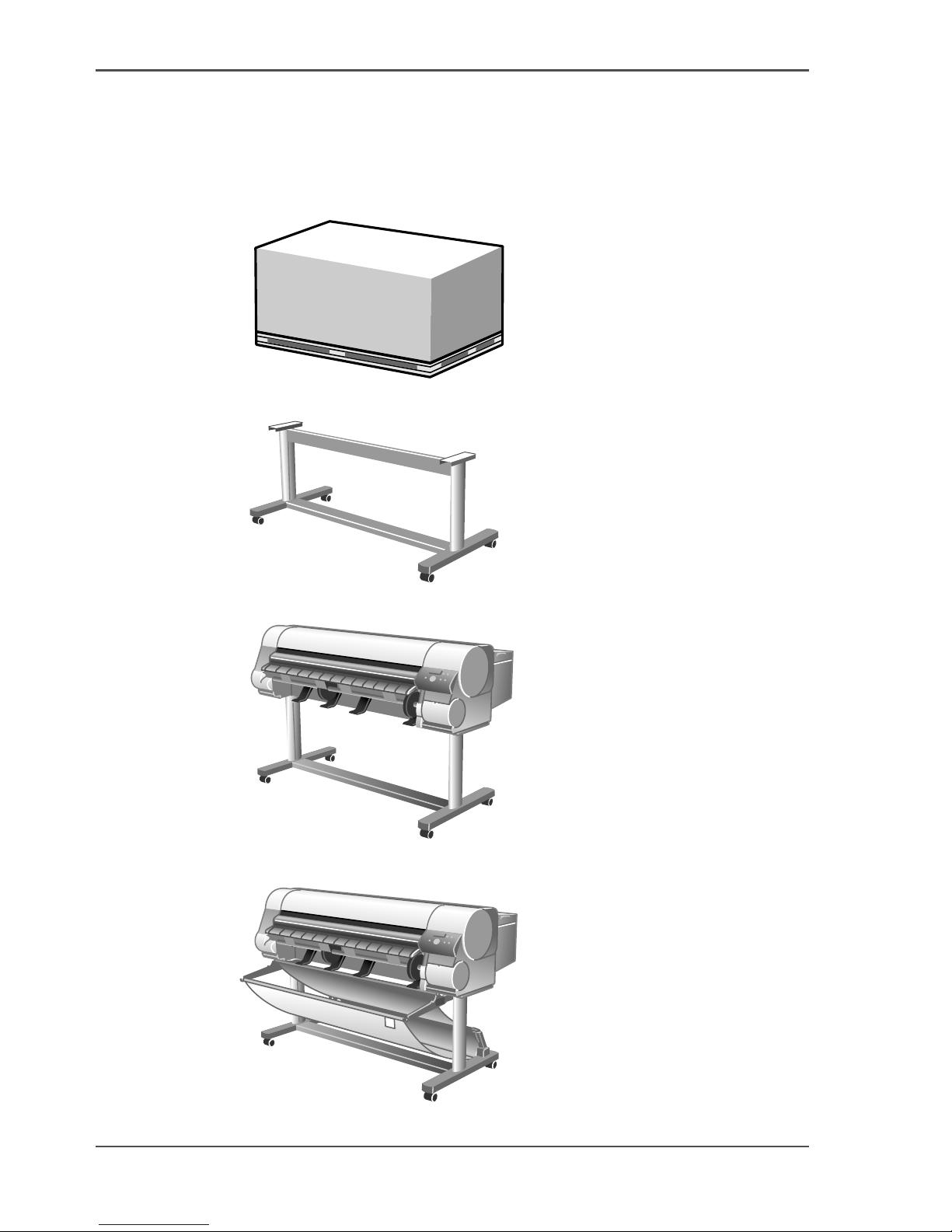
1. Unpack and Make Sure You Have Everything
[1]
2. Assembling the Stand
[2]
3. Installing the Printer
[3]
4. Attaching the Output Stacker
[4]
Page 7
7
Setup Flow
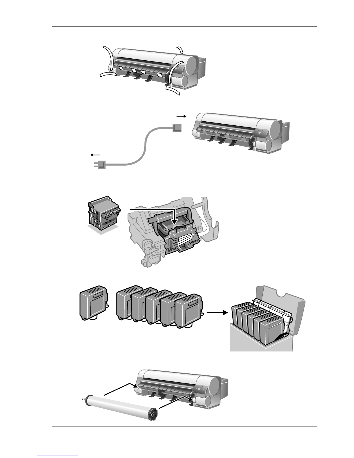
5. Removing the Packing Material
[5]
6. Connecting the Power
[6]
7. Stowing the Output Stacker
8. Installing the Printhead
[7]
9. Installing the Ink Tanks
[8]
10. Loading Roll Media
[9]
PC C PM M YBk
Page 8
8 Chapter 1 Read this first
Setup Flow
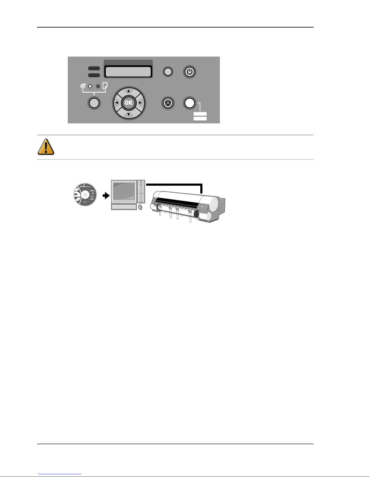
11. Adjusting the Print Status
Run an automatic adjustment of the printhead and media feed amount.
[10]
Attention: For USB connections, do not connect the cable before installing the
printer driver.
12. Installing the Software
[11]
Refer to chapter 5,"Using the Printer in a Network Environment", of the "User's
Guide".
Data
Message
Information Power
Cleaning
(3sec)
Stop/Eject Online
MAIN MENU
Adjust Printer
Offline
Menu
Page 9

9
Unpack and Make Sure You Have Everything
Unpack and Make Sure You Have Everything
Printer Set
[1]
[12]
Printer
[13]
Power Cable
[14]
Ink Tanks
■ Bk
■ C
■ PC
■ M
■ PM
■ Y
[15]
Roll holder
[16]
Spool Prevention Stays (x 4)
[17]
Cleaning Brush
[18]
Printhead
[19]
Hex driver
Page 10
10 Chapter 1 Read this first
Unpack and Make Sure You Have Everything
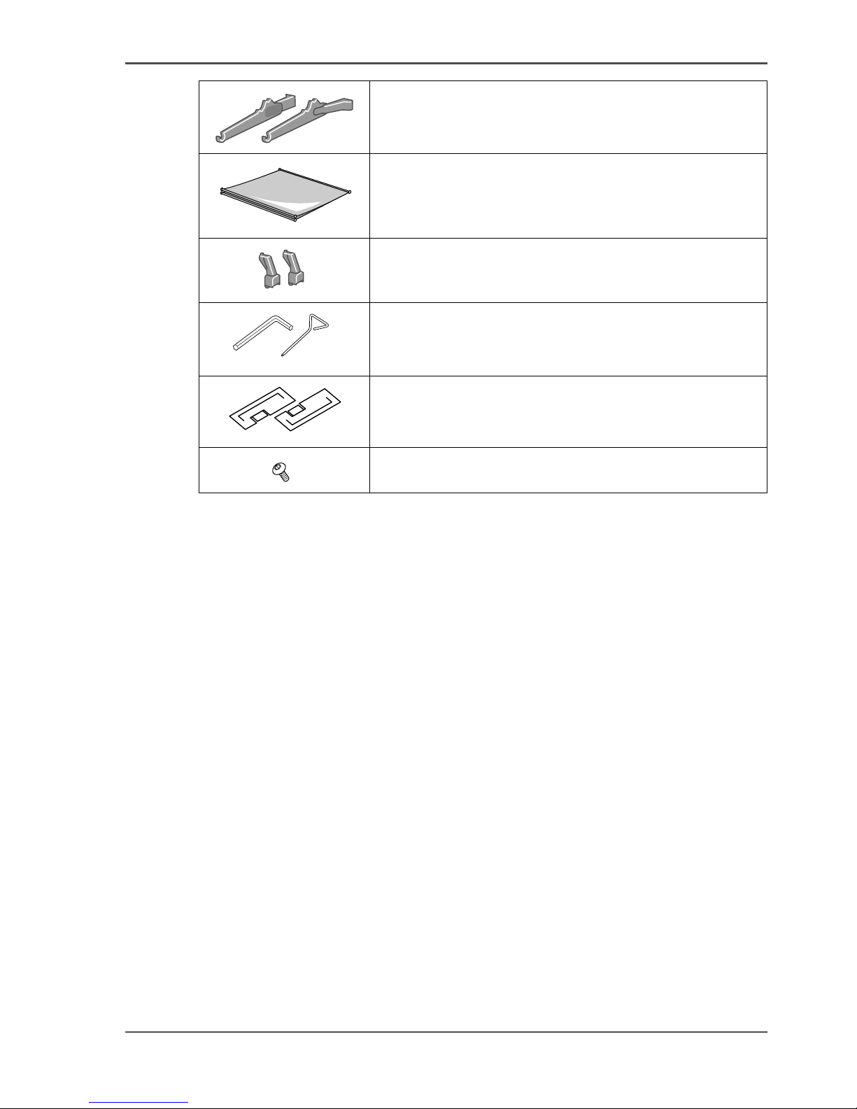
Stand Set
[2]
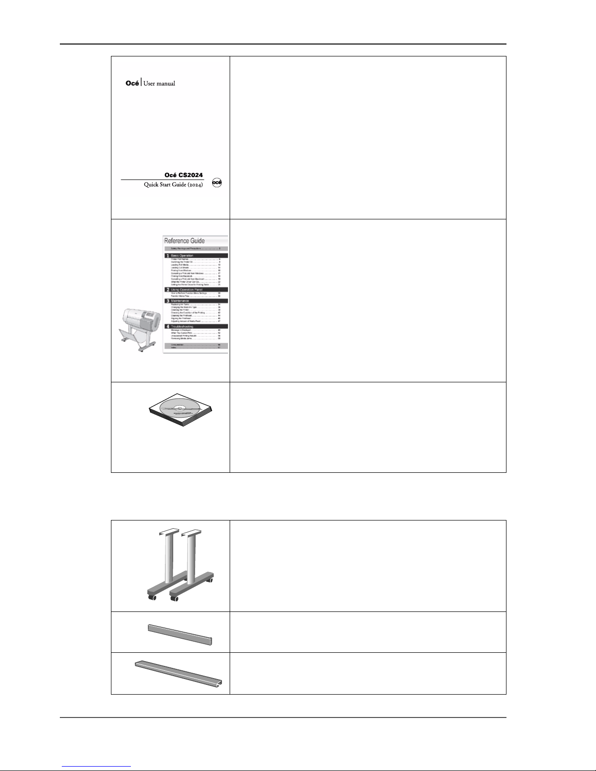
[20]
Quick Start Guide (This guide)
[21]
Reference Guide
[22]
■ User Software CD-ROM
■ User Manuals CD-ROM
■ Consumables Guide
■ Guide to Mounting the Spool Prevention Stay
■ Wara nt ee
■ Guide to Service and Support
[23]
Stand Legs L and R
[24]
Stand Upper Stay
[25]
Stand Lower Stay
Page 11
11
Unpack and Make Sure You Have Everything
[26]
Output Stacker Arms L and R
[27]
Output Stacker
[28]
Rod Holders (x 2)
[29]
■ M4 Hex Driver
■ M8 Hex Driver
[30]
Stand Extension Boards L and R
[31]
M4 Hex Screws (x 18)
Page 12
12 Chapter 1 Read this first
Unpack and Make Sure You Have Everything
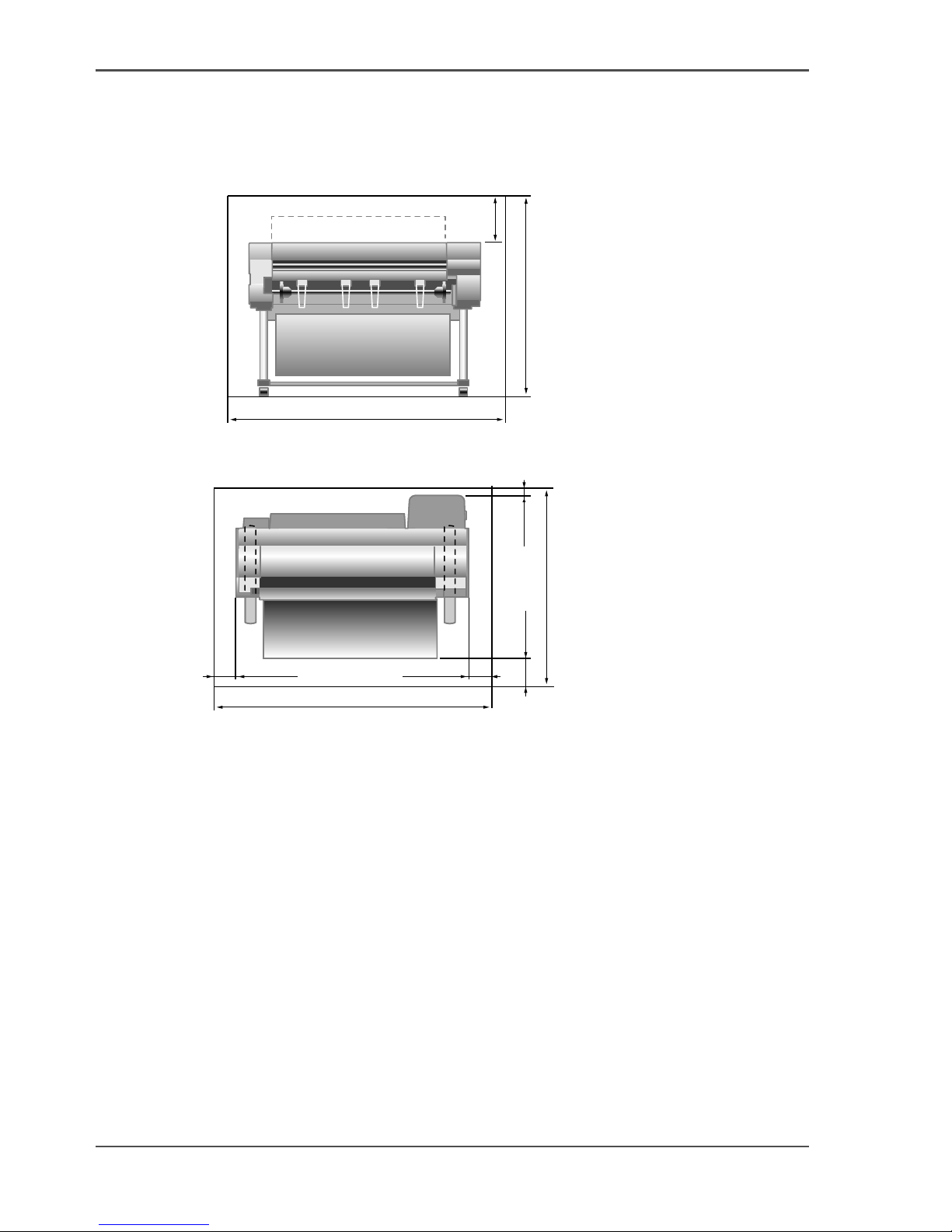
Installation Space
When you are installing the printer, reserve a space of the following dimensions or
larger.
[32]
[32] Height
[33]
[33] Width and Depth
mm5931
m
m023
2042 mm
1
1
1
4
Page 13
13
Assembling the Stand
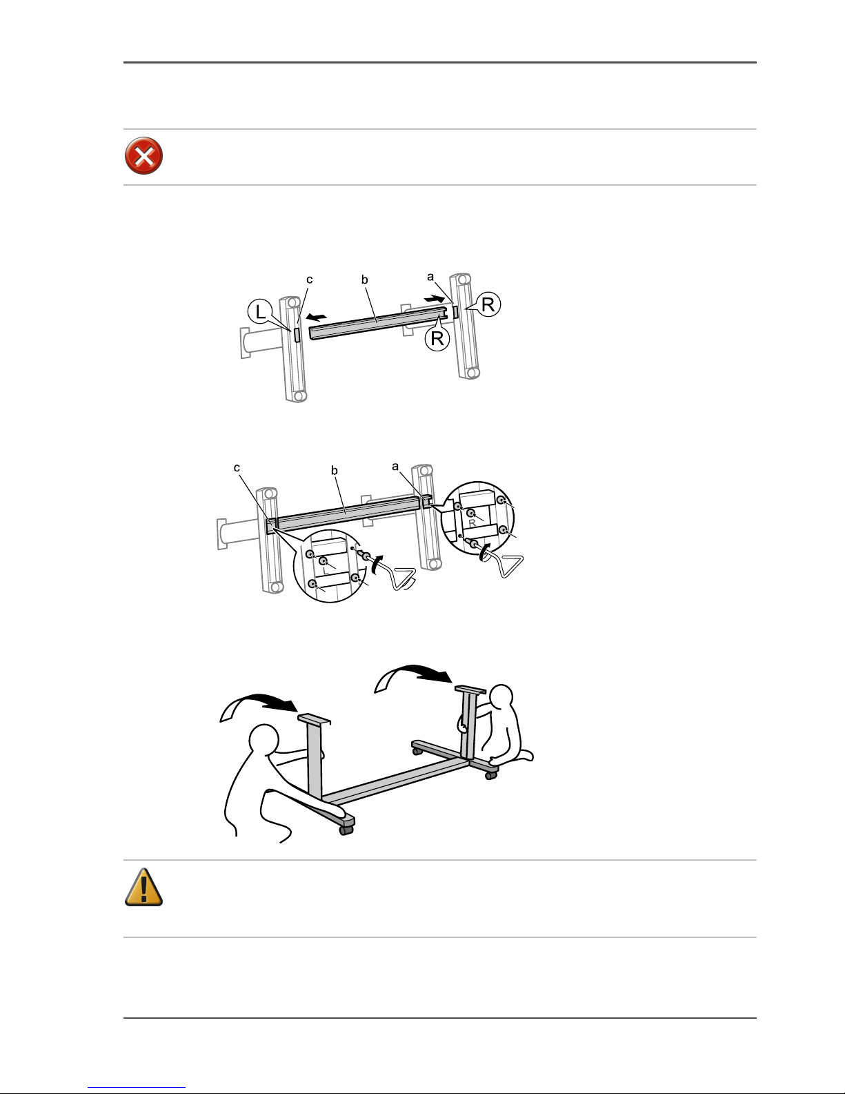
Assembling the Stand
Caution: Have at least 2 people work on assembling the stand. Attempting
this work alone may cause personal injuries or warp the stand.
1. Insert the right side of Stand Lower Stay (b) all the way into the hole in the side of
Stand Leg R (a), and insert the left side of Stand Lower Stay all the way into the hold
in the side of Stand Leg L (c).
[34]
2. Securely affix Stand Lower Stay (b) to Stand Leg R (a) and Stand Leg L (c) using 5
hex screws in each side.
[35]
3. Have 2 people grasp the stand from the left and right sides, and lift both sides of the
stand simultaneously.
[36]
Attention: When you are lifting the stand, make sure that you lift both sides at
the same time. Lifting one side at a time can cause the stand to warp and create
problems in the assembly.
Page 14
14 Chapter 1 Read this first
Assembling the Stand
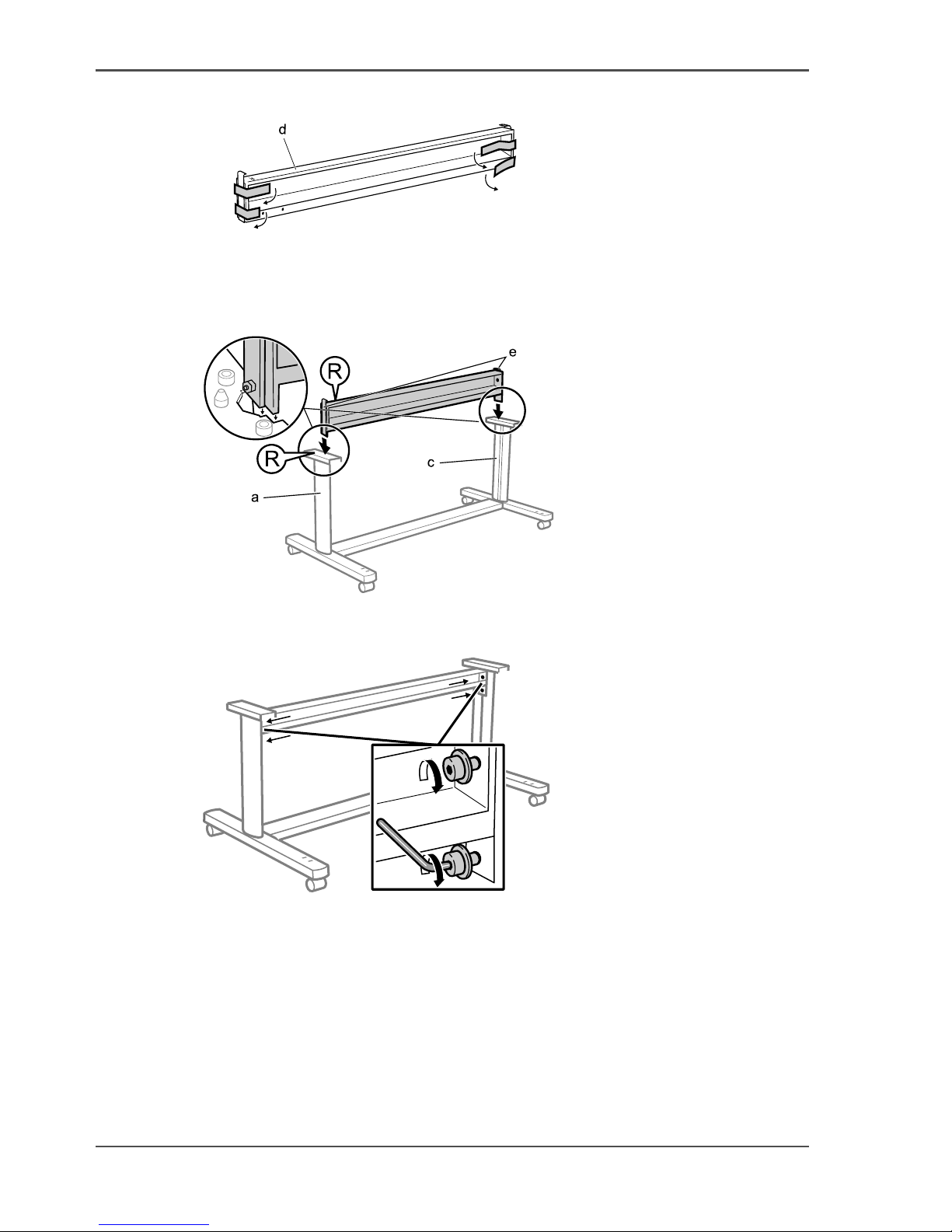
4. Remove the tape that is attached the left and right sides of Stand Upper Stay (d).
[37]
5. Arrange the Stand Upper Stay so that the bends in the brackets on the left and right
side (e) are facing up, and the side marked with an R is facing the Stand Leg R (a).
Insert the Stand Upper Stay into the groove between Stand Leg R (a) and Stand Leg
L (c).
[38]
6. Securely fasten the hex screws on the left and right side using the supplied M8 hex
driver to fix the Stand Stay in place.
[39]
Page 15
15
Assembling the Stand
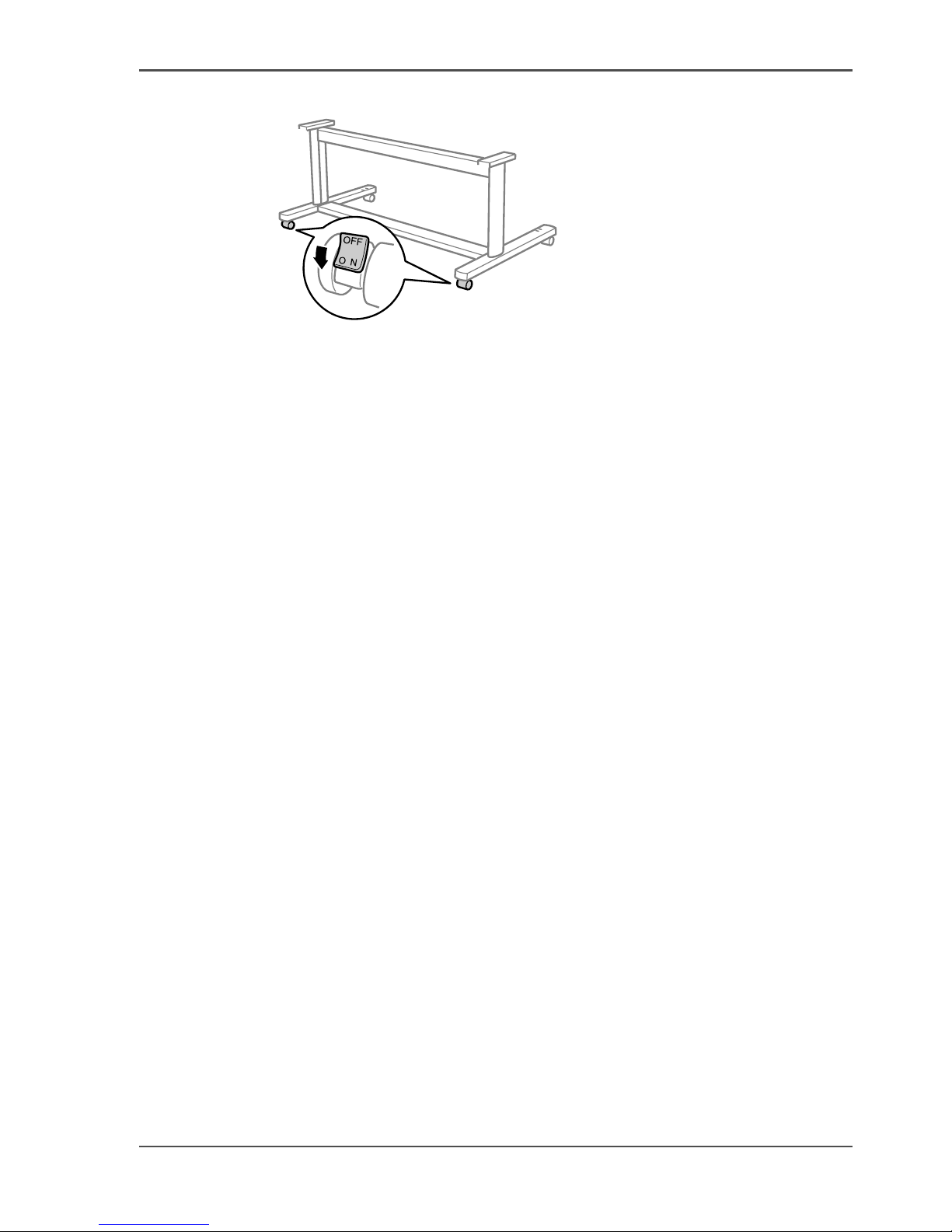
7. Place the Stand in the installation location and lock the front casters.
[40]
Page 16

16 Chapter 1 Read this first
Installing the Printer
Installing the Printer
Illustration
[41]
[42]
1. Remove the box from the printer body and clear out the packing material from above
the printer, then lift up the base of the printer one side at a time and clear out the
packing material from under the printer.
[43]
2. Fold and then peel off the double-sided tape (c) from the Stand Extensions Boards,
then stick Stand Extension Board (e) to the side of Stand Leg R (d) and Stand
Extension Board (g) to the side of Stand Leg L (f).
[44]
Page 17

17
Installing the Printer
3. Have 4 people grasp the handholds in the base of the printer body, then align the side
of the printer body (h) with the line on the Stand Extension Board (i) and put the
printer on the stand.
[45]
4. Remove Stand Extension Board (e) and (g) from the Stand Legs.
5. Securely affix the printer body to the stand using 2 hex screws on each side starting
from the bottom of the stand backing plate.
[46]
Page 18

18 Chapter 1 Read this first
Attaching the Output Stacker
Attaching the Output Stacker
1. Insert the Rod Holders (c) into holes on the back of Stand Leg L (a) and Stand Leg
R (b).
[47]
2. Insert Output Stacker Arm L (e) and Output Stacker Arm R (f) into the grooves (d)
in the left and right ends of the Stand Upper Stay, then attach them using 2 hex
screws.
[48]
3. Stretch out the Output Stacker fabric such that the white mark (g) on the fabric is at
the front right, and the center Output Stacker Rod (h) is at the back.
[49]
Page 19

19
Attaching the Output Stacker
4. Attach the Output Stacker Rod (j) in the center of the Output Stacker fabric to the
Rod Holder (i), and loop the hole in the fabric (k) over the hook (l) above the Rod
Holder.
[50]
Attention: Attach the Output Stacker Rods to the Rod Holders in front of the
Output Stacker Arm and at the very back of the Rod Holder. If the Output Stacker
Rods are attached to the second rod holder from the back, the media will not
enter the Output Stacker when ejected, and may cause dirtying or damage to the
print surface. Use the rod holder that is second from the back to temporarily hold
the Output Stacker Rod during maintenance.
5. Pull out to the back any slack in the paper stacker cloth, and then attach the two
Output Stacker Rods to the Rod Holders at the very back and front of the Output
Stacker Arm.
[51]
Page 20

20 Chapter 1 Read this first
Removing the Packing Material
Removing the Packing Material
1. Removing the tape and packing material that is attached to the printer body.
[52]
2. Open the top cover.
[53]
3. Lift up Release Lever (a) and remove the protective sheet (b) from the Platen, then
lower the Release Lever.
[54]
a
b
Page 21

21
Removing the Packing Material
4. Remove the belt stopper (c) screws, and then remove the warning card that is
attached by string, and the belt stopper.
[55]
Note: The Belt Stopper, screw and hex driver are needed for transporting the
printer.Store the Belt Stopper that you removed and the tools, etc. carefully in a safe
place.
5. Open the ejection guide.
[56]
c
Page 22

22 Chapter 1 Read this first
Removing the Packing Material
6. Remove the Roll Holder and remove the tape and packing material that is attached
to the Roll Holder.
[57]
7. Attach the four spool prevention stays (d) to the back of the ejection guide.
[58]
8. Close the ejection guide, and then close the top cover.
[59]
d
d
Page 23

23
Removing the Packing Material
9. Attach the Accessory Pocket to the left side of the rear surface of the printer.
[60]
This completes the printer assembly.
Page 24

24 Chapter 1 Read this first
Connecting the Power
Connecting the Power
1. Connect the power cable to the power supply connector in the left side of the printer.
[61]
2. Insert the power plug into the outlet. The shape of the power cable varies from
country to country.
[62]
Page 25

25
Installing the Printhead
Installing the Printhead
1. If the printer is off, press the Power button to switch the printer on.
[63]
2. Open the top cover.
[64]
Attention: Do not touch any areas other than as directed under any
circumstances. Doing so may damage the printer.
3. Pull the printhead fixer lever towards you as far as it will go.
[65]
4. Pull the printhead fixer cover up as far as it will go.
[66]
Information Power
Cleaning
(3sec)
Printer Setup
Open UpperCover
Page 26

26 Chapter 1 Read this first
Installing the Printhead
5. Hold the printhead by the grips (a) and remove it from the case, then remove the
protective orange cap 1 (b).
[67]
6. Push the tabs (d) on either side of printhead protective cap 2 (c) as shown in the
diagram, and pull down to remove the cap.
[68]
[69]
[69] Do not touch the nozzles (e) or the electrical contacts (f)
Attention: The printhead contains protective nozzle ink. If ink leaks, it may soil
the printer or peripherals. It is recommended that the protective cap 2 (c) should
be removed on the box in which the printhead was packed. If ink does leak, wipe
the ink off with a dry cloth. This ink is harmless to the human body.
a
b
d
c
e
f
Page 27

27
Installing the Printhead
Attention: When you are handling the printhead, always hold it by the grips (a)
on the left and right sides.
Attention: Do not touch the nozzles (e) or the electrical contacts (f) under any
circumstances. Doing so may damage the printhead or cause printing problems.
Attention: Never try to re-attach the protective caps or packing material that you
removed from the printhead.Dispose of these parts in accordance with local
garbage disposal regulations.
7. Insert the printhead into the carriage with the nozzles facing down and the electrical
contacts facing the printer.
[70]
8. Pull the printhead fixer cover toward you and down to lock the printhead in place.
[71]
Page 28

28 Chapter 1 Read this first
Installing the Printhead
9. Push the printhead fixer lever toward the back of the printer and then press down
until you hear it click.
[72]
10. Close the top cover.
[73]
Page 29

29
Installing the Ink Tanks
Installing the Ink Tanks
1. Open the right back cover.
[74]
2. Press the ink tank lever of the color you are loading to open the ink tank cover.
[75]
3. Gently shake the ink tank 7 or 8 times while it is still in the bag before removing it
from the bag. Insert the ink tank into the ink tank holder with the ink supply port
facing down and the color label facing away from you.
[76]
[77]
[77] Attention
Bk
Bk
bca
Page 30

30 Chapter 1 Read this first
Installing the Ink Tanks
Attention: When you are handling an ink tank, always hold it by the grips (a) on
the left and right sides.
Attention: Do not touch the ink supply port (b) or the electrical contacts (c)
under any circumstances. Doing so may cause printing problems or stain the
surrounding.
Page 31

31
Installing the Ink Tanks
4. Close the ink tank cover until you hear a click.
[78]
5. Repeat steps 1 to 4 to install the other ink tank colors.
6. Close the right back cover after you have installed all of the ink tank colors.
[79]
Page 32

32 Chapter 1 Read this first
Loading Roll Media
Loading Roll Media
Attention: When you are handling roll media, it is recommended that you wear
clean fabric gloves to protect the printing surface.
7. Raise the holder stopper lever (a) from the axle to unlock the holder stopper, and then
remove the holder stopper from the roll holder.
[80]
8. Position the roll so that the leading edge of media is at the bottom and facing away
from you, then push the roll holder firmly into the media roll from the right side until
it is flush with the media core.
[81]
9. Attach the holder stopper to the left side of the roll holder and insert it until it touches
the core of the roll, then push the holder stopper lever (a) down toward the shaft to
lock it.
[82]
a
a
Page 33

33
Loading Roll Media
10. Open the top cover and then open the ejection guide.
[83]
11. Orient the roll holder with the front edge of the roll media facing you, then align the
roll holder (b) with the left and right guide grooves (c) in the roll holder slot and
insert the roll holder.
[84]
b
b
c
c
Page 34

34 Chapter 1 Read this first
Loading Roll Media
12. Pull out the leading edge of the roll media keeping both left and right sides level, and
insert the media into the paper feed slot (d), and feed the paper until it reaches the
paperweight (e).
[85]
Once the media reaches the paperweight, it is automatically fed through to the
platen.
13. Close the ejection guide.
[86]
14. Grasp the center of the leading edge of the media and lift up the release lever.
[87]
e
d
Page 35

35
Loading Roll Media
15. Gently pull on the center of the leading edge of the roll media as far as the ejection
guide (f) and align the right edge of the media with the right edge of the paper
alignment line (g), then lower the release lever.
[88]
Attention: Do not pull strongly on the roll media when you align it with the
paper alignment line. The roll media may not feed out straight in some cases.
16. Close the top cover.
[89]
[90]
[90] Media Type is displayed.
You can load the types of media shown in the following table onto the roll holder.
Set the media type setting to match the type of the media you are using. The display
only shows the types of paper that can be used with the type of black ink loaded in
the printer.
g
f
Media Type
Plain Paper
Page 36

36 Chapter 1 Read this first
Loading Roll Media
[3]
17. Press [ ] or [ ] button to select the type of roll media you loaded, then press the
OK button.
[91]
[92]
An equals "=" mark is displayed to the left of the option to show the media type that
has been selected, and the printer begins preparing to feed the roll media.
Océ Media name Name Printer Operating Panel
IJM005 Océ Draft Paper Draft Paper
IJM020 Océ Standard Paper Standard Paper
IJM113 Océ Premium Paper 90g/m2 Premium Paper
IJM150 Océ SmartMatt Paper SmartMatt Paper
IJM215 Océ SmartFitPlus PhotoGloss SmartFit Photo
IJM250 Océ Smart Dry Photo Paper
Gloss
Smart Dry Photo
IJM311 Océ Double Matt Film DM Film
IJM138 Océ Transparent Paper 90g/m2 Transp. Paper
86500 Océ Check Plot Bond Check Plot Bond
86800 Océ Deluxe Bond Deluxe Bond
862024 Océ Premium Color Bond Premium Bond
AMPP07 Océ PrintPerfect Alternative
Matte Photopaper
PrintPerfect
GIPPLS7 Océ PhotoPerfect Plus Glossy
Photopaper
PhotoPerfect
PSDRY8 Océ Instant Dry Photopaper Photo Dry
868342 Océ Double Matte Film 4 mil Ink Jet Film
866020 Océ Color Vellum 20 lb. Premium Vellum
Media Type
HW Coated
Page 37

37
Loading Roll Media
Attention: Always set the Media Type setting to the type of roll media loaded
in the printer.If the media type setting does not match the loaded roll media,
printing quality may be reduced.
18. Press the [ ] or [ ] button to select the setting for the roll media length, and then
press the OK button.
[93]
[94]
When the printer has finished preparing to feed the roll media, Online is displayed
on the printer display and the printer is ready to print.
Roll Length Set
30.0m
Page 38

38 Chapter 1 Read this first
Adjusting the Print Status
Adjusting the Print Status
Adjusting the Printhead Position
Note: It is recommended that you run the printhead adjustment using the type of
media that you use most frequently.
Note: If you are using cut sheets, load at least one sheet of unused A3 or larger
paper (not the blank side of used paper) in landscape orientation.
19. Press the Online button to display MAIN MENU on the printer display.
[95]
[96]
20. Press the [ ] or [ ] buttons to select Adjust Printer then press the [ ] button.
[97]
[98]
21. Select Printhead Adj. then press the [ ] button.
[99]
[100]
Stop/Eject Online
Offline
Menu
MAIN MENU
Head Cleaning
MAIN MENU
Adjust Printer
Adjust Printer
Printhead Adj
Page 39

39
Adjusting the Print Status
22. Select Advanced Adj. then press the [ ] button.
[101]
[102]
23. Press the [ ] or [ ] button to select Ye s , then press the OK button.
[103]
[104]
The printhead adjustment pattern is printed.
[105]
The printer scans the resulting printout as it is printed, and automatically calibrates
the printhead adjustment values.
When the calibration has finished, the printer returns online.
Printhead Adj
Advanced Adj.
Advanced Adj.
Yes
Page 40

40 Chapter 1 Read this first
Adjusting the Print Status
Media Feed Adjustment
Attention: Before you adjust the amount of media feed, you need to configure
the media type setting using the operation panel to match the media loaded in the
printer. If the media type selection does not match the media loaded in the printer,
you will not achieve the correct print results and the printing quality will be
reduced.
24. Press the Online button to display MAIN MENU on the printer display.
[106]
[107]
25. Press the [ ] or [ ] buttons to select Adjust Printer then press the [ ] button.
[108]
[109]
26. Press the [ ] or [ ] buttons to select Adjust Band, then press the [ ] button.
[110]
[111]
Stop/Eject Online
Offline
Menu
MAIN MENU
Head Cleaning
MAIN MENU
Adjust Printer
Adjust Printer
Adjust Band
Page 41

41
Adjusting the Print Status
27. Select Standard Adj. then press the [ ] button.
[112]
[113]
28. Press the [ ] or [ ] button to select Ye s , then press the OK button.
[114]
[115]
The media feed adjustment pattern is printed.
[116]
The printer scans the printout as it is printing and automatically calibrates the media
feed settings for the currently selected media type. There are separate media feed
settings for each different media type.
When the calibration is complete, the Online lamp turns on and the printer is ready
to print.
Adjust Band
Standard Adj.
Standard Adj.
Yes
Page 42

42 Chapter 1 Read this first
Installing for Windows
Installing for Windows
Connecting USB
Attention: Do not connect the cable yet. If you connect the cable now, this may
prevent the printer driver from installing correctly.
Attention: Make sure that the printer is switched on.
Attention: If your are using Windows Server 2003 or Windows XP, or Windows
2000, you must log in as a member of the Administrator group.
Attention: Be sure to use a USB 2.0 standard connection cable.
29. Mount the provided User Software CD-ROM in the computer CD-ROM drive.
[117]
30. Start the wizard. Double-click setup.exe which you can find on the Océ CS2044
CD-rom.
[118]
Page 43

43
Installing for Windows
31. Follow the procedure to complete the installation.
When the port connection screen appears, connect the USB cable to the printer and
the computer.
[119]
Connecting the LAN Cable
Note: The following operating systems support a TCP/IP network connection:
Windows Server 2003, Windows XP, Windows 2000, Windows Me, Windows 98, or
Windows NT 4.0 (Service Pack 6 or later).
Attention: When this printer is connected to and used on a network, switch the
printer on then check the LINK lamp to confirm that it lights and remains on.
This lamp lights green with a 100-Base-TX connection and lights yellow for a
10-BaseT connection.
Attention: Refer to the “Chapter 5 of the User’s Guide” if the connection does
not operate properly.
32. Connect the LAN port on the rear of the printer to the HUB port with a LAN cable.
[120]
USB Connection
USB
Printer back Computer
Page 44

44 Chapter 1 Read this first
Installing for Windows
Installing the Printer Driver
Attention: If you are using Windows Server 2003, Windows XP, Windows
2000, or Windows NT 4.0, you must log in as a member of the Administrator
group.
Attention: If you are using Windows NT 4.0, open Network from the Control
Panel in the Start menu and confirm that Microsoft TCP/IP Printing is
installed and on the list on the Service sheet.
33. Connecting the Printer to a Network for the First Time
Mount the provided User Software CD-ROM in the computer CD-ROM drive.
[121]
34. Start the wizard. Double-click setup.exe which you can find on the Océ CS2044
CD-rom.
[122]
35. Follow the procedure to complete the installation.
Page 45

45
Stowing the Output Stacker
Stowing the Output Stacker
1. Grasp the centre of the front output stacker rod (a) and pull it up slightly.
[123]
2. Then simply pull the output stacker rod (a) out towards you.
[124]
a
a
Page 46

46 Chapter 1 Read this first
Stowing the Output Stacker
3. Lower the output stacker rod (a).
[125]
Note: To reattach the output stacker, perform the steps above in reverse.
a
Page 47

47
If the output stacker arm disengages
If the output stacker arm disengages
Illustration
[126]
[127]
1. Turn the output stacker arm (a) in the direction indicated by the arrow.
[128]
d
e
d
f
a
Page 48

48 Chapter 1 Read this first
If the output stacker arm disengages
2. Slide the rotated output stacker arm (b) in until it clicks into the 2 holes (c). If the
rear output stacker rod (d) has dropped down, fit the output stacker arm (b) in place
before re-attaching the output stacker rod.
[129]
c
b
d
 Loading...