

Page 1

o
More Power When
Printing
Océ
ColorStream
User Manual
Continuous Printing
System
Page 2

Copyright
Copyright © Océ 2008–2009
All rights reserved. This documentation may not be reproduced, copied, changed or transmitted in any form, either in whole or in part, without written authorization from Océ.
Océ does not assume any responsibility or offer any guarantee regarding the information
contained in this document and excludes in particular any implied warranty claims regarding
the market capability or usability for a certain purpose. Océ also reserves the right to revise
this documentation from time to time and amend the content without announcing these
changes.
The designations Océ ColorStream®, Océ VarioStream®, Océ JetStream®, Océ VarioPrint®,
Océ Web Buffer®, Océ PRISMA®production, Océ CustomTone®, Océ FlexiDark®, Océ
TonerSafe™ and Océ InkSafe™ are protected by trademark.
All hardware and software names used are trademarks of their respective owners.
We also offer courses in our Training Center for Océ ColorStream.
Information:
Phone +49 (0)8121 72 3940
Fax +49 (0)8121 72 3950
Océ Printing Systems GmbH
ITC
Postfach 1260
85581 Poing
Germany
Edition: A29246-X31-X-1- 80/2009-1176
Page 3

Contents
Chapter 1
Notes on the Printing System Documentation..............................................11
Notes on the Printing System Documentation — Overview................12
Guide through the Documentation.........................................................13
Notes on Help...........................................................................................15
Notes on the Help - Overview...........................................................15
Opening Help......................................................................................16
Navigating in Help..............................................................................18
Contents........................................................................................18
Index..............................................................................................19
Search............................................................................................20
Opening Direct Help...........................................................................21
Symbol Conventions................................................................................24
Symbols in the text............................................................................24
Symbols in figures.............................................................................25
Other Documents.....................................................................................27
Manufacturer of the printing system......................................................28
Statutory requirements............................................................................29
Chapter 2
Safety.................................................................................................................31
Safety — Overview...................................................................................32
Intended Purpose ....................................................................................33
Flagging of safety directives ..................................................................34
Warning and information signs..............................................................35
Accident and Damage Prevention..........................................................37
Accident and damage prevention - overview..................................37
Personal Representations..................................................................38
Operation............................................................................................39
Transportation, assembly and installation, repair...........................42
Fire, disposal.......................................................................................44
Safety Regulations and Standards.........................................................45
Safety regulations and standards — overview................................45
CE Mark...............................................................................................48
Accident prevention regulation for replacement carts (option).....49
Chapter 3
Description of the Printing System.................................................................51
Description of the Printing System — Overview...................................52
Main Modules...........................................................................................53
3
Contents
Page 4

Doors and Covers.....................................................................................54
Internal View.............................................................................................56
Internal View — Overview.................................................................56
Photoconductor unit...........................................................................58
Transfer unit........................................................................................60
Filter module.......................................................................................61
Console................................................................................................62
Printing method........................................................................................64
Operating Elements.................................................................................67
Operating Elements - Overview........................................................67
On key..................................................................................................69
Additional Operator Panels...............................................................70
Operator Attention Light....................................................................72
Operator Attention Light (OPAL) — Overview...........................72
Operator Attention Light (OPAL)/Bundle 11 Version.................73
Operator Attention Light (OPAL)/Bundle 10 Version.................75
Operating elements in the printing system......................................77
Paper specifications.................................................................................78
Chapter 4
Description of the Operator Panel...................................................................81
Description of the Operator Panel — Overview.....................................82
A tool bar...................................................................................................83
Toolbar — Overview..........................................................................83
Buttons and Displays in the Left Area..............................................84
Buttons and Displays in the Center Area .........................................86
Frame toolbar.....................................................................................90
Menu Tree.................................................................................................91
Menu Tree — Overview.....................................................................91
'General' Menus.................................................................................93
'General' menus — overview......................................................93
'User management' menus.........................................................94
'User' menus.................................................................................95
'Security' menus...........................................................................96
'ColorStream' Menus.........................................................................97
'ColorStream' Menus — Overview..............................................97
'Displays' menus...........................................................................99
'Configuration' menus................................................................100
'Setup' menus.............................................................................101
'Replace consumables' menus..................................................102
Menu display..........................................................................................104
Chapter 5
Working with the Operator Panel.................................................................105
Working with the Operator Panel — Overview....................................106
4
Contents
Page 5

Managing User Settings (Key Operator)..............................................107
Managing User Settings (Key Operator) — Overview..................107
Extended password protection (option).........................................109
'Add user' .........................................................................................110
'Delete user' .....................................................................................111
Set Password / 'General' Tab..........................................................112
Releasing and blocking menus and elements/'User rights' tab....113
Setting language/'User profile' tab.................................................114
Managing User Settings (Operator).....................................................115
Managing User Settings (Operator) — Overview..........................115
Log on as user and request an access ticket..................................116
Change Password / 'Password' Tab................................................118
Changing language/'User profile' tab.............................................119
Log off as user..................................................................................120
Selecting settings and entering values................................................121
Applying or resetting settings...............................................................122
Working with Setups..............................................................................123
Working with Setups — Overview..................................................123
Creating a new setup or changing a setup.....................................124
Importing a Setup.............................................................................125
Exporting a Setup.............................................................................127
Managing Resources.............................................................................129
Managing Resources — Overview..................................................129
Installing Resources.........................................................................130
Deleting Resources...........................................................................132
Editing 'Replace consumables' menus on the operator panel...........133
Chapter 6
Operating the Printing System......................................................................137
Operating the Printing System — Overview........................................138
Powering on the Printing System.........................................................139
After printing has stopped, switch the printing system back to 'Ready'
.................................................................................................................142
Inserting the paper web.........................................................................143
Inserting the Paper Web..................................................................143
Adjusting the Pressure Rollers........................................................148
Synchronizing the Paper Path.........................................................150
Affixing the paper web..........................................................................152
Removing the paper web .....................................................................155
Opening or Closing the Doors on the Printing System.......................156
Opening or Closing the Doors on the Printing System —
Overview...........................................................................................156
Opening Right Doors........................................................................157
Closing Right Doors.........................................................................159
Opening Left Doors..........................................................................161
5
Contents
Page 6

Closing Left Doors............................................................................163
Replacing the Developer Station..........................................................165
Replacing the developer station — overview................................165
Preparing the replacement cart.......................................................169
Removing the Developer Station....................................................171
Removing the developer station...............................................171
Storing the Developer Station in the Developer Station Shelf.177
Putting the Developer Station on the Stacking Tray...............181
Installing the Developer Station......................................................183
Removing the Developer Station from the Developer Station
Shelf.............................................................................................183
Replacing the Developer Station from the Stacking Tray.......187
Installing the developer station.................................................189
Replacing the Light Protection Cover.............................................194
Removing the Light Protection Cover.......................................194
Installing the Light Protection Cover.........................................197
Completing developer station replacement...................................198
Checking the print image ......................................................................199
Printing Test Print Jobs.........................................................................200
Printing Test Print Jobs — Overview..............................................200
'5C_PrintQualityInspection.600' Test Print Job..............................202
Test Print Job "ColorProof.ipds".....................................................207
Test Print Job 'ColorProof.ipds' — Overview...........................207
Test Print Job 'ColorProof.ipds' — Page 1...............................208
Test Print Job 'ColorProof.ipds' — Page 2...............................211
Test Print Job 'ColorProof.ipds' — Page 3...............................213
Test Print Job 'ColorProof.ipds' — Page 4...............................214
Test Print Job 'ColorProof.ipds' — Page 5...............................215
Test Print Job 'ColorProof.ipds' — Page 6/7............................216
Test Print Job "ColorProof.ipds_pdf"..............................................218
Test Print Job 'ColorProof.ipds_pdf' — Overview...................218
Test Print Job 'ColorProof.ipds_pdf' — Page 8........................219
Test Print Job 'ColorProof.ipds_pdf' — Page 9........................222
Test Print Job 'ColorProof.ipds_pdf' — Page 10......................223
Test Print Job 'ColorProof.ipds_pdf' — Page 11/12.................225
Test Print Job "ColorProof.pcl"........................................................227
Test Print Job 'ColorProof.pcl' — Overview.............................227
Test Print Job 'ColorProof.pcl' — Page 1..................................228
Test Print Job 'ColorProof.pcl' — Page 2..................................230
Test Print Job 'ColorProof.pcl' — Page 3..................................231
Test Print Job 'ColorProof.pcl' — Pages 4-10...........................232
Test Print Job 'ColorProof.pcl' — Page 11................................234
Test Print Job 'ColorProof.pcl' — Page 12................................236
'SpotColorPalette.pcl' Test Print Job..............................................237
6
Contents
Page 7

Optimizing the Color Printing................................................................239
Optimizing the Color Printing — Overview....................................239
Performing a Color Test...................................................................242
Calibrating the Colors of the Printing System...............................244
Calibrating the Colors of the Printing System — Overview....244
Printing Test Pages for Color Calibration.................................246
Scanning Test Pages for Color Calibration...............................249
Analyzing Test Pages for Color Calibration..............................253
Correcting Color Separation Shifts.......................................................255
Calibrating the Data Integrity Mark Sensor..........................................257
Converting the Printing System............................................................261
Emptying Condensation Water.............................................................263
Switching off the Printing System........................................................264
Chapter 7
Cleaning the Printing System........................................................................267
Cleaning the Printing System — Overview..........................................268
Cleaning Agents and Cleaning Intervals..............................................270
Cleaning the Surface of the Developer Stations..................................273
Cleaning the Surface of the Developer Stations — Overview......273
Swiveling off Developer Stations....................................................274
Cleaning Developer Station Surface...............................................275
Swiveling on developer stations.....................................................282
Cleaning the Paper Input.......................................................................283
Cleaning the Paper Output....................................................................286
Cleaning the Paper Path........................................................................289
Checking the Paper Path........................................................................296
Cleaning the Toner Suction System.....................................................301
Cleaning the Paper Brake Dust Filter....................................................305
Cleaning the Surface of the Printing System.......................................307
Cleaning the replacement cart for developer stations (option)..........308
Cleaning the Developer Station Shelf (Optional)................................309
Chapter 8
Replacing Consumables.................................................................................311
Replacing Consumables — Overview..................................................312
Order Numbers and Packing Units.......................................................313
Toner.......................................................................................................314
Toner Bottle Identification with Océ TonerSafe.............................314
Toner Supply with Additional Colors.............................................317
Refilling Toner (Standard: 6 kg / 13.2 lb Toner Bottle)..................318
Refilling Toner (Option: 1 kg / 2.2 lb Toner Bottle)........................324
Replace waste toner box..................................................................331
Filling a Toner Box...........................................................................335
Developer................................................................................................336
7
Contents
Page 8

Replacing the Developer - Overview..............................................336
Draining the Developer Mixture......................................................337
Fill in Developer................................................................................340
Chapter 9
Replacing Expendables..................................................................................345
Replacing Expendables — Overview....................................................346
Order Numbers and Packaging Units for Expendables......................349
Replacing the Belt..................................................................................350
Replacing the Belt — Overview.......................................................350
Replacing the Photoconductor Belt in the Upper Print Unit.........352
Removing Photoconductor Belt in Upper Print Unit and Replacing
Photoconductor Blade................................................................352
Insert a photoconductor belt in the upper print unit...............358
Replacing the Photoconductor Belt in the Lower Print Unit.........364
Removing Photoconductor Belt in Lower Print Unit and Replacing
Photoconductor Blade. ..............................................................364
Inserting a Photoconductor Belt in the Lower Print Unit........370
Replacing the Transfer Belt in the Upper Print Unit......................376
Removing the Transfer Belt in the Upper Print Unit - Prepara-
tion...............................................................................................376
Removing Transfer Belt in the Upper Print Unit......................380
Insert the Transfer Belt in the Upper Print Unit.......................385
Insertion of a Transfer Belt in the Upper Print Unit (Comple-
tion)..............................................................................................392
Replacing the Transfer Belt in the Lower Print Unit......................395
Removing the Transfer Belt in the Lower Print Unit - Prepara-
tion...............................................................................................395
Removing the Transfer Belt in the Lower Print Unit ...............398
Inserting the Transfer Belt in the Lower Print Unit..................402
Inserting the Transfer Belt in the Lower Print Unit..................408
Running in a Belt..............................................................................411
Replacing Corotrons..............................................................................412
Replacing the corotron — overview...............................................412
Removing the cleaning corotron slide-in unit or charge corotron
slide-in unit of the photoconductor unit.........................................413
Installing the cleaning corotron slide-in unit or charge corotron slide-
in unit of the photoconductor unit .................................................416
Removing the cleaning corotron slide-in unit of the transfer unit.418
Installing the cleaning corotron slide-in unit of the transfer unit .420
Removing the reload corotron slide-in unit of the transfer unit....421
Installing the reload corotron slide-in unit of the transfer unit....423
Removing the recharge corotron slide-in unit of the transfer unit.425
Installing the recharge corotron slide-in unit of the transfer unit.427
Replacing corotron wire...................................................................428
8
Contents
Page 9

Replacing the Cleaning Brush...............................................................433
Replacing the cleaning brush — overview.....................................433
Removing the cleaning brush of the photoconductor unit...........434
Installing the cleaning brush of the photoconductor unit.............437
Removing the cleaning brush of the transfer unit.........................439
Installing the cleaning brush of the transfer unit...........................441
Replacing fine filter................................................................................443
Replacing the cleaning felt....................................................................448
Replacing the Smoothing Rollers.........................................................454
Replacing the smoothing rollers — overview................................454
Removing the smoothing rollers....................................................455
Installing smoothing rollers.............................................................461
Replacing Expendables in Expert Mode...............................................469
Chapter 10
Correcting Errors.............................................................................................473
Correcting Errors — Overview .............................................................474
Processing messages on the operator panel ......................................475
Remote Diagnosis..................................................................................479
Allowing Remote Access — Overview...........................................479
Permitting or Blocking Remote Diagnosis.....................................480
Activating or Deactivating Remote Support..................................481
Correcting Fusing Problems..................................................................483
Correcting Print Image Errors...............................................................484
Appendix A
Technical Data.................................................................................................491
Technical Data — Overview..................................................................492
Technology and Print Speed.................................................................493
Paper........................................................................................................496
Electrical Values and Power Input........................................................498
Mechanical Conditions..........................................................................500
Environmental Conditions.....................................................................502
Replacement cart for developer stations (option)...............................503
Ruler for Checking Paper Path Synchronization..................................504
Appendix B
Comments.......................................................................................................507
Your comments on this User Manual...................................................508
9
Contents
Page 10

10
Contents
Page 11

Chapter 1
Notes on the Printing
System Documentation
Page 12
Notes on the Printing System Documentation — Overview
Introduction
The purpose of this documentation is to ensure that all printing system-related work is
carried out safely and correctly. It contains safety directives that must be strictly observed.
Each section is divided into small, easy-to-understand subject areas. Overviews at the
beginning of the sections help you to find the precise information you are looking for
quickly.
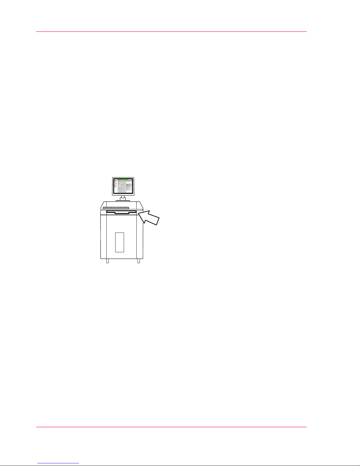
Storage Tray for the User Guide
The user guide should always be kept near the console in the storage tray.
Overview
You will find information on the following topics:
■
‘Guide through the Documentation’ on page 13
■
‘Notes on the Help - Overview’ on page 15
■
‘Symbols in the text’ on page 24
■
‘Symbols in figures’ on page 25
■
‘Other Documents’ on page 27
■
‘Manufacturer of the printing system’ on page 28
■
‘Statutory requirements’ on page 29
Chapter 1 - Notes on the Printing System Documentation12
Notes on the Printing System Documentation — Overview
Page 13

Guide through the Documentation
Introduction
Documentation available to you on the Océ ColorStream includes a printed user guide
and help on the operator panel. This help is updated with every new version of the oper-
ator panel software.
Security
This section gives you all necessary information on how to safely and efficiently operate
the printing system.
Description of the printing system
This section shows the structure of the printing system, describes the operating elements
and explains the printing principle. You will also find information on paper types and
how to handle the paper.
Description of the Operator Panel
This section describes the individual areas of the operator panel with the most important
menus, buttons and icons.
Working with the operator panel
This section explains how you manage all user settings, how you select or enter parameters
on the operator panel, how you collect special settings for frequently recurring print jobs
using setups, how you manage resources for printing operation and how you replace
consumables and expendables using the operator panel.
Operating the printing system
This section describes how to power the printing system on and off and the procedure
for inserting, affixing and removing the paper web, and also contains all other information
that you will need to operate the printing system.
Cleaning the printing system
This section shows you how often to clean the different components and how to carry
out this cleaning.
Chapter 1 - Notes on the Printing System Documentation 13
Guide through the Documentation
Page 14

Replacing consumables
This section describes in detail all the steps required to replace consumables. It also provides
the order numbers and package units for all consumables.
Replacing expendables
This section describes in detail all the steps required to replace expendables. It also provides
the order numbers and package units for all expendables.
Correcting Errors
This section shows you how to locate and remedy errors using the messages displayed on
the operator panel. It also describes how you can enable remote access to allow remote
diagnosis by Service during print operation . You will also find information on how to
correct any fusing or print image errors.
Technical data
This section contains the most important technical data for the printing system.
You can use the ruler for controlling the paper path synchronization to assign the marks
on the paper input to certain form lengths.
Index
The fastest way to find particular topics is via the detailed index at the end of the user
guide.
Your comments on this user guide
We are interested in your opinion on this user guide for the Océ ColorStream. You can
help us improve this user guide by answering the questions in this section.
Chapter 1 - Notes on the Printing System Documentation14
Guide through the Documentation
Page 15

Notes on Help
Notes on the Help - Overview
Help target group
This Help is designed for the "Operator" and "Key Operator" user groups. This Help
should enable an "Operator" or "Key Operator" to use the printing system safely, appro-
priately and efficiently.
Menus that are available to the Service group only are not displayed in this Help. The
Océ service documentation is available for Service.
Contents of Help
This Help describes the printing system and operator panel with the following main
groups:
■
'General'
■
'VarioStream' or 'ColorStream' or 'JetStream'
■
'Paperpath Manager'
■
With Océ VarioStream 9000 CustomTone or full-color printing systems and with
Océ ColorStream, also: 'Web Buffer'
Any connected pre- and post-processing devices are not covered in this Help. It is assumed
that the user is able to operate these devices properly and observes the safety instructions
in the relevant documentation sources for these pre- and post-processing devices.
Calling up Help
There are two ways you can access help topics:
■
Help button on the toolbar and subsequent navigation via contents, index or search:
‘Opening Help’ on page 16
‘Contents’ on page 18
‘Index’ on page 19
‘Search’ on page 20
■
Direct Help via the F1 key:
‘Opening Direct Help’ on page 21
Chapter 1 - Notes on the Printing System Documentation 15
Notes on the Help - Overview
Page 16
Opening Help
To open Help
#
Proceed as follows:
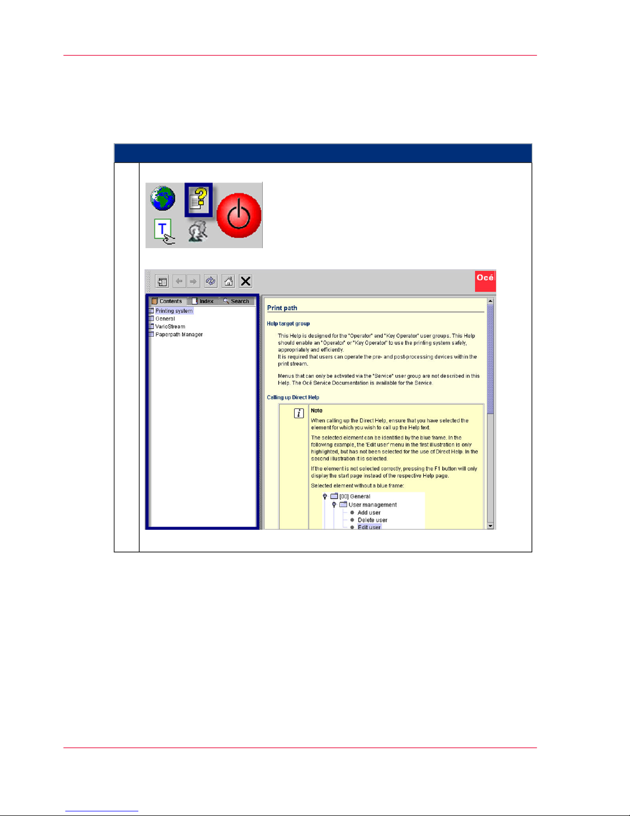
Click on the following button in the frame toolbar:
The Help window opens. The navigation area is displayed initially:
The width of the navigation area can be changed with the mouse.
1.
Chapter 1 - Notes on the Printing System Documentation16
Opening Help
Page 17

Function of the Buttons in the Help Window
#
FunctionButton
Hides or displays the navigation area with the following tabs:
■
‘Contents’ on page 18
■
‘Index’ on page 19
■
‘Search’ on page 20
When the navigation area is hidden, more space is available to view
the help topics.
Switches between the last help topics (backwards or forwards).
Reloads the displayed help topic, in case not all the necessary content
was loaded (e.g. graphics).
Switches from any help topic directly to the Help start page.
Closes Help.
Chapter 1 - Notes on the Printing System Documentation 17
Opening Help
Page 18
Navigating in Help
Contents
To call up Help topics via the contents
#
Proceed as follows:
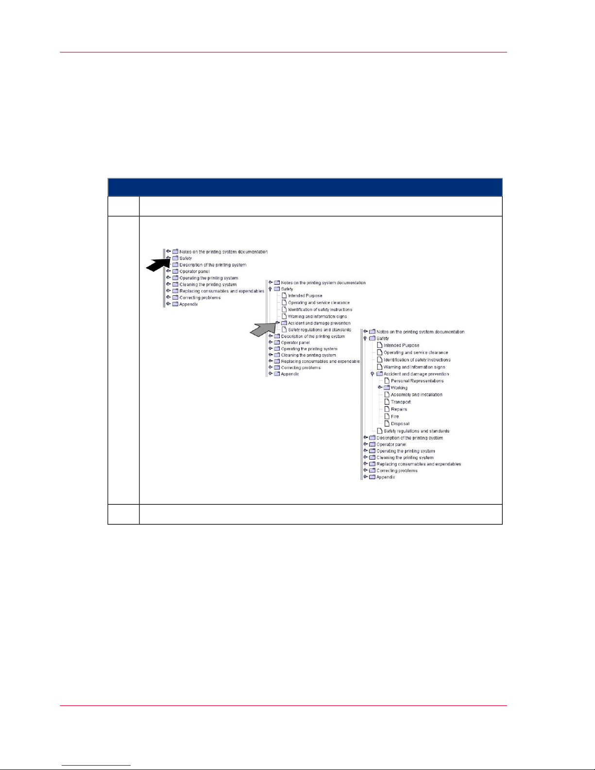
Click on the 'Contents' tab.1.
Click the buttons of the individual help levels to fade them in and out.
Example:
[13]
2.
Click on a help topic.3.
Chapter 1 - Notes on the Printing System Documentation18
Contents
Page 19
Index
Introduction
Entries on the 'Index' tab are sorted alphabetically. Any number of secondary keywords
can be attached to a primary keyword.
To select information via the Index
#
Proceed as follows:
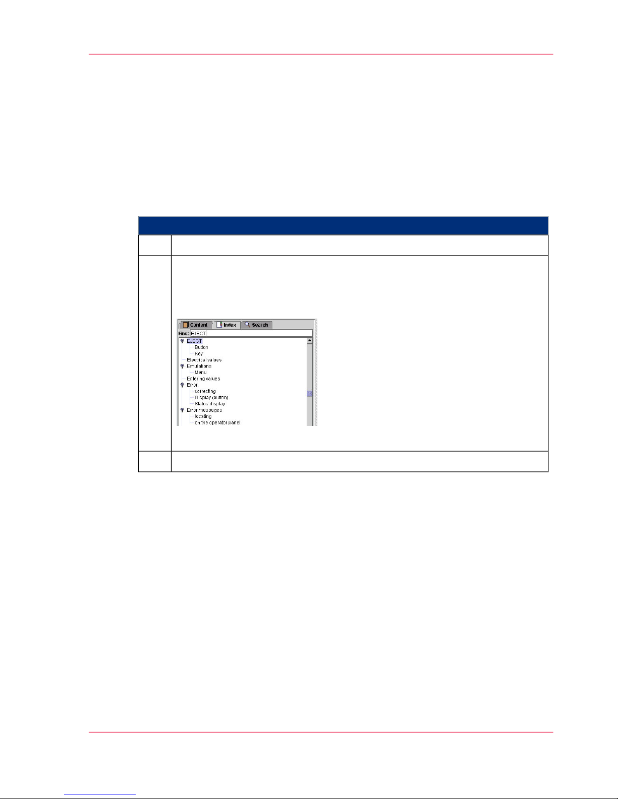
Click on the "Index" tab.1.
Scroll through the index entries
or
enter text (including partial words) into the 'Search' field and press Enter.
Example:
[14]
2.
Click on a help topic3.
Chapter 1 - Notes on the Printing System Documentation 19
Index
Page 20
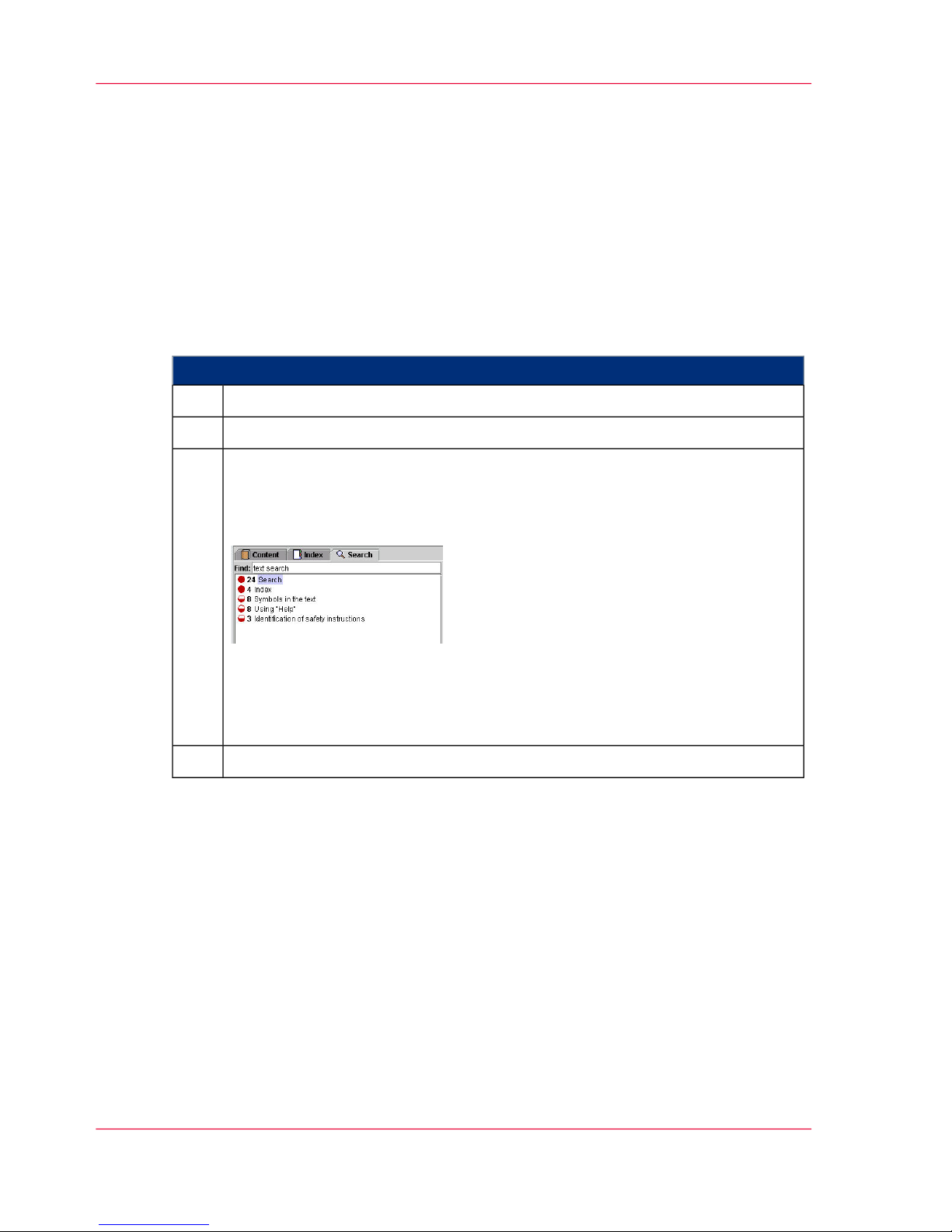
Search
Introduction
You can access the full text search function via the "Search" tab. The full text search is
used to find one or more specific words in the entire Help. Uppercase or lowercase is not
relevant for the search. Partial words cannot be found.
To call up information via the full text search
#
Proceed as follows:
Click on the 'Search' tab.1.
Enter the text in the 'Search' input field.2.
Press Enter.
The search results are listed by the title of the corresponding help topic, and
are sorted by level of matches and the frequency in which the word appears in
the help topic. Example:
The circle in the first column indicates the level of matching. The more filled
the circle is, the better the result matches the text that was searched for.
The number in the second column of the search result indicates how often it
occurs in the Help topic.
3.
Click on a help topic4.
Chapter 1 - Notes on the Printing System Documentation20
Search
Page 21
Opening Direct Help
Introduction
Context-sensitive Direct Help provides detailed information on all:
■
Menus
■
Operating elements in menus
■
Errors and warnings
#
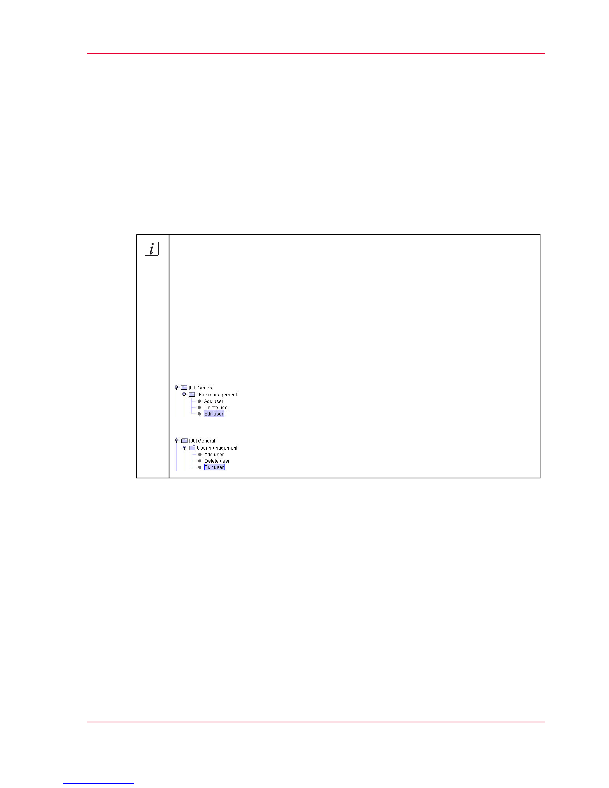
Note
When calling up the Direct Help, ensure that you have selected the element
for which you wish to call up the Help text.
The selected element can be identified by the blue frame. In the following example, the 'Edit user' menu in the first illustration is only highlighted, but has
not been selected for the use of Direct Help. In the second illustration it is
selected.
If the element is not selected correctly, pressing the F1 button will only display
the start page instead of the respective Help page.
Selected element without a blue frame:
Selected element with a blue frame:
Chapter 1 - Notes on the Printing System Documentation 21
Opening Direct Help
Page 22
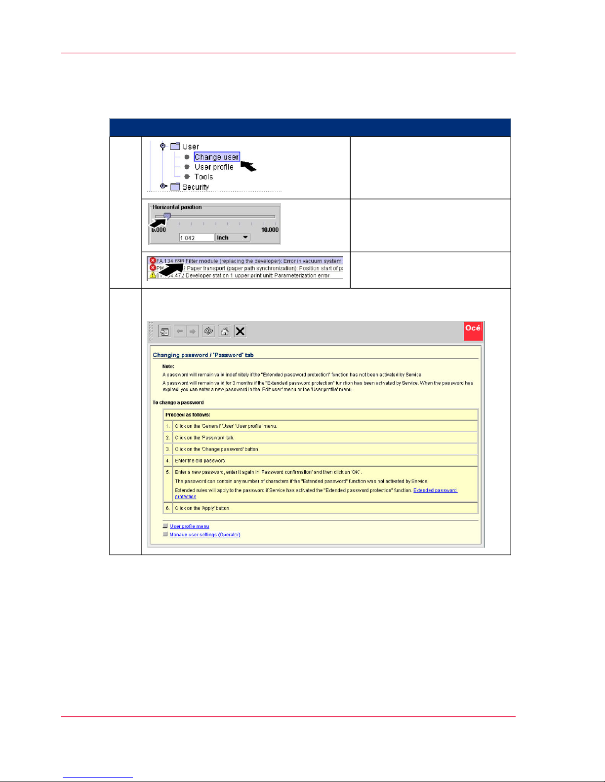
To call up the Direct Help
#
Proceed as follows:
Select menu
or
1.
select operating element
or
select message
Press F1.
The Help window opens. The navigation area is initially hidden, e. g.:
2.
Chapter 1 - Notes on the Printing System Documentation22
Opening Direct Help
Page 23
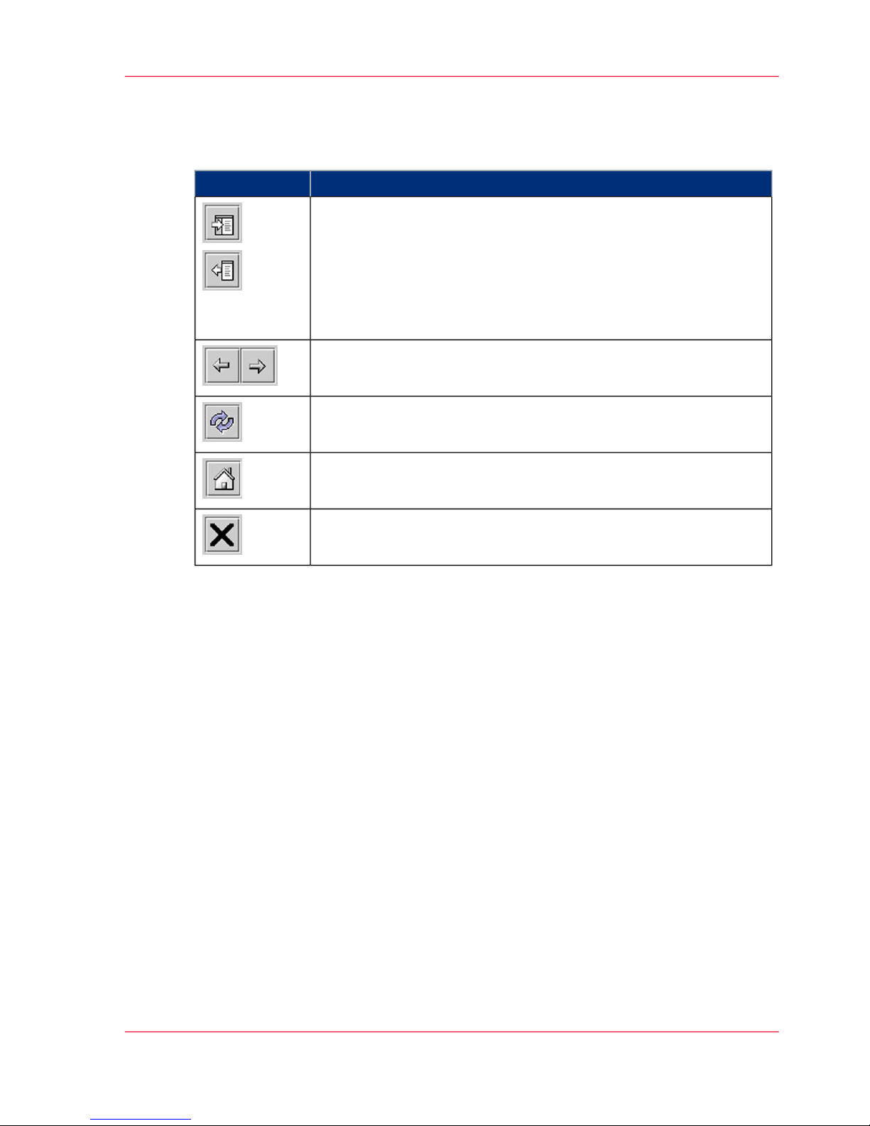
Function of the Buttons in the Help Window
#
FunctionButton
Hides or displays the navigation area with the following tabs:
■
‘Contents’ on page 18
■
‘Index’ on page 19
■
‘Search’ on page 20
When the navigation area is hidden, more space is available to view
the help topics.
Switches between the last help topics (backwards or forwards).
Reloads the displayed help topic, in case not all the necessary content
was loaded (e.g. graphics).
Switches from any help topic directly to the Help start page.
Closes Help.
Chapter 1 - Notes on the Printing System Documentation 23
Opening Direct Help
Page 24

Symbol Conventions
Symbols in the text
Display of operating elements on the operator panel
The operating element description is shown in inverted commas on the operator panel,
e.g.
'Configuration' menu.
Notes
Note:
This symbol indicates notes - tips for operating the Océ ColorStream.
Safety directives
Symbols are used for the safety directives, as well as different alert words depending on
the degree of danger: see ‘Flagging of safety directives ’ on page 34.
Chapter 1 - Notes on the Printing System Documentation24
Symbols in the text
Page 25

Symbols in figures
Introduction
If not indicated otherwise, diagrams and illustrations of actions depict the starting position
of the respective component for the described step.
To ease understanding, the illustrations depict the components that are directly relevant
to the immediate context in a larger line thickness.
Note:
As a result of the continuous technical further development, it may be that some of the
details on the images in the documentation are not always completely up-to-date with
the delivered printing system.
Arrows
Arrows denote the positions where you should perform an action or observe something
in particular. The colors of the arrows denote the type of actions and the sequence in
which they are performed:
#
MeaningArrow
Black arrow: Direction arrow
Perform this action first
Grey arrow: Direction arrow
Perform this action next
If further actions are depicted in an illustration, the numbers
on the arrows indicate the sequence of these further actions.
White arrow: Note arrow
An action should be performed in this area.
Overview Graphics
To provide a clear overview, the VarioStream 9000 and ColorStream printing systems
also indicate the side of the printing system where the action is to be performed.
Chapter 1 - Notes on the Printing System Documentation 25
Symbols in figures
Page 26
#
MeaningOverview graphic
Paper input
Left-hand side of printing system
Right-hand side of printing system
Filter module
Paper output
Chapter 1 - Notes on the Printing System Documentation26
Symbols in figures
Page 27
Other Documents
In Addition to the User Guide
The following documents are also provided for every printing system, in addition to the
user guide:
#
Order numberTitle
A29246-X34-X-n-79 (multi-lingual)Safety information
A29249-X5-X-n-mm59Paper specification
A29246-X27-X-n-mm80'Océ Web Buffer' User Guide
Note:
The respective edition of the document is indicated in the order number by the digit
"n", for example: Edition 3: n = 3. The letters "mm" stand for the language code of the
document:
■
German: mm = --
■
English: mm = 76
■
French: mm = 77
■
Italian: mm = 72
■
Spanish: mm = 78
■
Dutch: mm = 54
■
Japanese: mm = 5Z
■
Chinese: mm = 5D
Chapter 1 - Notes on the Printing System Documentation 27
Other Documents
Page 28

Manufacturer of the printing system
Océ ColorStream
The printing system Océ ColorStream was manufactured by:
Océ Printing Systems GmbH
Postfach 1260
85581 Poing
Germany
Chapter 1 - Notes on the Printing System Documentation28
Manufacturer of the printing system
Page 29

Statutory requirements
Technical changes
The information, data and instructions in this documentation were up-to-date at the
time of going to press. The right of technical modifications due to further development
of the printing system is reserved. For this reason, the information, illustrations and de-
scriptions in this documentation cannot give rise to any claims for modifications or addi-
tions to printing systems that have already been shipped and accepted.
Liability
No liability is accepted for damages resulting from:
■
Failure to comply with the documentation
■
Errors due to improper handling
■
Work performed incorrectly on the printing system
■
Use of non-original expendable parts, replacement parts and accessories
■
Use of non-original consumables
■
Unauthorized modification and retrofitting of the printing system by the agent or the
agent’s personnel.
Chapter 1 - Notes on the Printing System Documentation 29
Statutory requirements
Page 30

Chapter 1 - Notes on the Printing System Documentation30
Statutory requirements
Page 31

Chapter 2
Safety
Page 32

Safety — Overview
Security
This section gives you all necessary information on how to safely and efficiently operate
the printing system.
Safety Directives
In addition to the safety directives in section ‘Accident and damage prevention - overview’
on page 37, you must also observe the safety directives elsewhere in this documentation.
Please also observe the safety directives in the documentation for any pre-processing and
post-processing devices that may be connected.
Overview
You will find information on the following topics:
■
‘Intended Purpose ’ on page 33
■
‘Flagging of safety directives ’ on page 34
■
‘Warning and information signs’ on page 35
■
‘Accident and damage prevention - overview’ on page 37
■
‘Safety regulations and standards — overview’ on page 45
Chapter 2 - Safety32
Safety — Overview
Page 33

Intended Purpose
Océ ColorStream
The Océ ColorStream printing system shall only be considered as being used for its intended purpose if the notices and instructions in this documentation are strictly observed:
■
The printing system is intended solely for printing materials that comply with the
paper specification requirements (see ‘Other Documents’ on page 27).
■
The printing system must only be operated with the recommended consumables (see
‘Order Numbers and Packaging Units for Expendables’ on page 349).
■
The printing system must only be operated under the prescribed operating conditions
(see ‘Technical Data — Overview’ on page 492).
Any other use of the printing system can cause damage to the printing system or property
as well as injury to persons.
Chapter 2 - Safety 33
Intended Purpose
Page 34

Flagging of safety directives
Definition
The following notational conventions are used for the safety directives in the text of the
manual:
#
Alert word
Type or source of danger and consequences of failure to observe the
safety directives
Instructions on avoiding danger
Symbol
Different alert words are used for the safety directives, depending on the degree of danger.
Two classes of safety directives
Caution:
Warns against dangers that could lead to injuries.
Attention:
Warns against situations that could lead to damage to the printing system or disruptions
to operation.
Example of a safety directive
Attention:
Fluid can get inside the printing system. This could cause irreparable damage to the
electrical and mechanical components.
Do not place cleaning fluids on top of or in the immediate vicinity of the printing system.
Take care to prevent fluids from seeping into the printing system.
Chapter 2 - Safety34
Flagging of safety directives
Page 35

Warning and information signs
Identification of Danger Points
The following signs are affixed inside the printing system at potential danger points:
#
MeaningLabel
Warning: Live electric parts
There are live electric parts behind safety covers bearing this
sign. These safety covers may only be removed by authorized
Océ Service personnel.
Warning about rotating parts
In these areas, body parts (especially fingers), unprotected long
hair and loose hanging clothing (e.g. ties, jewelry, loose belts
etc.) can be pulled in by the rotating parts of the printing system, trapped and crushed.
Warning about hot components
In order to prevent burns, you must observe the cooling periods
and other directives specified in the documentation for all work
in these areas.
Observe documentation
For all work in this area, you must observe the relevant instructions in the documentation.
Disposal
This symbol means that separate, proper disposal of the components at the end of the product service life is obligatory in the
EU Member States. The black bar indicates that the regulation
became effective on August 13, 2005. Directive: 2002/96/EC.
The "Environmental Protection Use Period (EPUP)", applicable
in the People's Republic of China, amounts to 20 years for the
printing system.
This EPUP, which does not record consumables and expendables according to regulations, does not affect the liability for
defects and no special guarantee is given for the printing system.
Chapter 2 - Safety 35
Warning and information signs
Page 36

Additional warning and information signs on the Océ ColorStream
#
MeaningSign
Warning regarding laser beams
Components that produce laser beams are located behind protective covers bearing this sign. These protective covers may
only be removed by authorized Océ Service personnel.
Chapter 2 - Safety36
Warning and information signs
Page 37

Accident and Damage Prevention
Accident and damage prevention - overview
Overview
You will find information on the following topics:
■
‘Personal Representations’ on page 38
■
‘Operation’ on page 39
■
‘Transportation, assembly and installation, repair’ on page 42
■
‘Fire, disposal’ on page 44
Chapter 2 - Safety 37
Accident and damage prevention - overview
Page 38

Personal Representations
Agent
An agent is any individual or legal entity (corporate body) that uses or commissions the
use of the printing system.
Operator
The Operator
■
is trained directly on the printing system as to how to operate it and has been instructed
on the tasks assigned to them. They are familiar with the contents of the documentation.
■
is aware of the potential dangers of improper handling of the printing system.
■
has been informed about necessary safety installations, safety precautions and operating
conditions.
■
has been instructed or commissioned by the agent to operate the printing system.
■
can load defined setups.
Key Operator
The Key Operator
■
is an operator with a higher qualification assigned additional tasks by the agent (e.g.
assignment of user rights and passwords).
■
can also display or hide menus for the different operators and accordingly adapt the
menu structure to the respective requirements.
■
can compile defined printing system configurations to create setups.
Service
Service staff are specialized Océ personnel who carry out all work on and with the printing
system that operators may not (e.g., any work on the power circuits in the printing system).
Chapter 2 - Safety38
Personal Representations
Page 39

Operation
Introduction
Observe the following instructions when operating the printing system:
Service personnel
Only operators, key operators and Service personnel may operate the printing system.
The printing system must not be operated by persons under the influence of alcohol or
drugs, or by persons taking certain types of medication, such as psychotropic drugs.
Before operating the printing system, carefully read through the documentation. Please
ask if you do not understand anything in the documentation (e. g. regarding Service).
In cases of emergency, power off the printing system off immediately with the main
switch. In the event of damage to the casing, power cable or operating elements, or pen-
etration of fluids or foreign bodies, call the appropriate Service representative.
Do not wear any loose hanging clothing (e. g. ties, sleeves, scarves), necklaces and bracelets,
loose belts, rings and unprotected long hair. These can catch in the drive mechanisms or
moving parts of the printing system and cause injury.
Safety covers
Do not attempt to remove safety covers yourself; do not manipulate safety equipment
such as the switches monitoring the safety covers, fuses etc., and do not perform any work
not intended to be performed by operators. Such action can cause accidents and may also
damage the printing system.
Safe operation of the printing system is guaranteed only when the outer paneling is fully
mounted. Only properly and fully affixed casing ensures:
■
Protection from electrical shocks
■
Protection against injury from mechanical parts, e.g. cuts, drawing in, crushing
■
Protection against the spread of fire
■
Sufficient cooling of the printing system.
Keep all doors, trims, flaps and covers closed while the printing system is in operation.
This ensures that limit values for electromagnetic compatibility are not exceeded. Noise
emission is also minimized.
Chapter 2 - Safety 39
Operation
Page 40

Cleaning
Always use an industrial vacuum cleaner with a grounded suction tube, rubber nozzle
and filter set for fine dust. An explosion-proof industrial vacuum cleaner must be used
for large toner quantities because there can be a high build-up of static charge when
draining toner spill.
When cleaning the printing system, observe the instructions in the following sections:
■
‘Cleaning the Printing System — Overview’ on page 268
■
‘Cleaning Agents and Cleaning Intervals’ on page 270
Foreign bodies, noises
Make sure that no objects (e.g. jewelry chains, paper clips, coins etc.) or liquids get into
the interior of the printing system, since this may result in electric shocks or short circuits.
Do not place objects on the printing system, and especially do not place containers with
fluid, such as drinking bottles, glasses, cups or vases on top of or in the immediate vicinity of the printing system.
Should the printing system emit any unusual or noticeable noises or smells, power off
the printing system and contact your Service engineer.
Cooling, Heat, Emissions
Do not obstruct the cooling ducts, since this may result in overheating or combustion
while the device is in operation.
Make sure there is an adequate supply of fresh air and cooling air to the room in which
the printing system is located (see ‘Cooling air, fresh air, and air purity’ on page 502).
Do not obstruct the operating and maintenance areas of the Océ ColorStream printing
system with other devices or objects.
During operation, the inner area of the fuser module in the printing system becomes very
hot (greater than 500°C/932°F). Before doing any work on or around the fuser module,
always allow it to cool down for the specified length of time. Failure to observe the directives in this documentation could result in burns.
The ozone produced when the photoconductor and transfer belts are loaded is suctioned
off within the printing system and then transformed into oxygen through a catalytic filter
Chapter 2 - Safety40
Operation
Page 41

system. The life cycle of the filter system is designed so that it does not have to be replaced
during the lifetime of the printing system.
During printing, the ozone concentration is below the maximum allowable work place
concentration (MAC) of 0.1 ppm (0.2 mg/m3). With proper ventilation, harmful con-
centrations do not occur even if the filter system fails entirely. For ventilation, see ‘Cooling
air, fresh air, and air purity’ on page 502.
Consumables and Expendables
Observe the safety directives given in the manual for:
■
Toner
■
Developer
■
Fine filter
■
Photoconductor belt
■
Transfer belt
■
Cleaning agent
Keep all consumables for the printing system out of the reach of children. Store consum-
ables away from containers used for food and drink.
Optical wave guide
If your printing system has an optical wave guide connection:
Never look directly down a glass fiber cable or glass fiber cable connection. The laser
beams in fiber optic devices can injure your eyes.
Laser
If the printing system includes a laser:
Never look directly into a laser beam or laser optics. Never move a tool into the area of
the laser beam so that you do not unintentionally diffract the laser beam. The laser beams
in fiber optic devices can injure your eyes.
Remote control via LAN
If you operate the printing system from a remote operator panel:
The access ticket ensures that only one user at a time can access the printing system.
Warning and Information Signs
Observe all warning and information signs on and in the printing system (see ‘Warning
and information signs’ on page 35).
Chapter 2 - Safety 41
Operation
Page 42

Transportation, assembly and installation, repair
Transport
The printing system may only be transported by Service personnel or authorized transport
companies.
Assembly and installation
Observe the following instructions when assembling and installing the printing system:
■
The printing system may only be assembled and installed by Service personnel.
■
The printing system must have a dedicated electrical connection or type B plug connection (complying with VDE directives, EN 60950).
■
Do not route the lines and cables in such a way that they can be trodden on or tripped
over.
■
A fume hood should be installed over the fuser module (without a security detector).
In very seldom cases, paper that has been caught in the fuser module will be damaged
by the infrared fusing and will begin to smoke. However, even in this case there is no
danger of fire because the affected component is immediately isolated from the remaining printing system by sealed bulkheads. This bulkhead is part of a proven safety
concept and does not affect the availability of the printing system after the jammed
paper has been removed.
■
All printing system accessories and options must comply with statutory regulations
and directives for safety, electromagnetic compatibility, telecommunications terminal
devices as well as with the specifications published by Océ Printing Systems GmbH.
■
The installation of other accessories may constitute a violation of these requirements
and directives, and may also damage the printing system.
■
Consult Service personnel for details on which accessories and options are permitted
for the printing system.
■
With the exception of optical wave guide connections, all data, signaling, process,
measurement and control lines mapping the printing system with other devices must
be properly grounded.
■
Data transmission lines should neither be connected nor disconnected during electrical
storms.
Repairs
Repairs to the printing system must only be carried out by Service personnel. Access to
locked areas and areas which can only be opened with special tools is reserved for Service
personnel. Opening the device without authorization and improperly effected repairs
may put operators at considerable risk.
Chapter 2 - Safety42
Transportation, assembly and installation, repair
Page 43

The access ticket used by the Service technician ensures that the printing system cannot
be used via an LAN from a remote operator panel during repair work.
Chapter 2 - Safety 43
Transportation, assembly and installation, repair
Page 44

Fire, disposal
Fire
Observe the following instructions:
■
Poisonous gases can occur in any fire. They can also result from the printing system
Océ ColorStream.
■
Self-contained breathing apparatus must be worn when fighting fire or smoke emission.
Instructions to this effect should be deposited at the fire alarm center and with the
local fire-fighting force.
Disposal
Océ operates a system by which expendables and consumables can be returned for environmentally sound disposal.
Keep all used parts and consumables that are to be returned for disposal for collection by
Service or the contracted shipping company. These will be recycled or disposed of appropriately by Océ Printing Systems GmbH or a contracted disposal company.
Chapter 2 - Safety44
Fire, disposal
Page 45

Safety Regulations and Standards
Safety regulations and standards — overview
Introduction
The printing system Océ ColorStream complies with the relevant safety requirements for
information technology equipment. It meets the following national and international
safety regulations and standards:
Safety Standards
#
Fitting of high-voltage systems with electrical equipmentVDE 0160
Safety of information technology systems including electronic office machines
VDE 0805
Low voltage directive
EC directive for harmonization of the legal requirements
of member states regarding electrical equipment for use
within certain voltage limits (modified by EC Directive
93/68/EWG)
2006/95/EC
Safety of information technology equipment including
electrical business equipment
IEC 60950
Safety of information technology equipment, including
office devices, in connection with the CE mark
EN 60950-1 (Europe)
Safety of information technology equipment including
electrical business equipment
UL 60950-1 (USA)
Standard for safety of information technology equipment
including electrical business equipment
CAN-CSA Standard
CSA 60950-1 (Canada)
Certified Safety
General device safety is verified by:
■
VDE/GS
Chapter 2 - Safety 45
Safety regulations and standards — overview
Page 46

■
TÜV/GS
■
Or similar
Electromagnetic Compatibility
#
EMVDirective
EC Directive for harmonization of the legal requirements
of member states regarding Electromagnetic Compatibility
(modified by Directive 91/263/EEC, 92/31/EEC, and
Directive 93/68/EEC)
89/336/EWG
EuropeEN 55024
EN 55022 / Class A
USAFCC Part 15 Subpart B
Class A
CanadaC108.8-M1983 (Class
A)
Environmental Standards
#
Environmental Conditions - TestDIN / IEC 68
Environmental conditions for products
Permitted noise emissions from devices
EN 60721 - Part 3
RoHSDirective
EC directive on the restriction of the use of certain hazardous substances in electrical and electronic equipment =
RoHS Directive (binding since 06/30/2006)
2002/95/EG
WEEDirective
EC directive on waste electrical and electronic equipment
= WEEE Directive (binding since 06/30/2006)
2002/96/EG
Recooler
The recooler complies with the following regulations and directives:
■
EMV-Directive 2004/108/EC
■
Low Voltage Directive 2006/95/EC
■
DIN EN 378 Refrigerating systems and heat pumps — safety and environmental requirements
Chapter 2 - Safety46
Safety regulations and standards — overview
Page 47

■
RoHS Directive
■
TÜV/GS
Overview
Here you will find additional information on the following topics:
■
‘CE Mark’ on page 48
■
‘Accident prevention regulation for replacement carts (option)’ on page 49
Chapter 2 - Safety 47
Safety regulations and standards — overview
Page 48

CE Mark
Océ ColorStream
The printing system Océ ColorStream fulfills the requirements of the EC directives
89/336/EWG, "Electromagnetic Compatibility" and 73/23/EWG "Low Voltage Directive".
The CE Mark indicates that the printing system complies with these EC directives.
The printing system is a Class A product (EN 55022). This product may cause radio interference in a domestic environment. In this case, the agent may be required to take appropriate measures to correct the interference at his or her own expense.
The printing system can cause the power supply to fluctuate if the power network is not
in order. According to EN 61000-3-11, the printing system should only be used on
premises that have a network with a continuous current-carrying capacity of 100 A per
phase or are supplied by a distribution network of 400/230 V.
The agent must ensure that the printing system is operated in a power supply network
that meets these requirements. If necessary, consult the power company to ensure that
the continuous current-carrying capacity of the power system at the connection point to
the public power grid is sufficient to connect the device.
Connected Devices
The optional "maintenance cart for developer stations" and "movable developer station
shelf" are also CE-certified.
All other devices that are connected to the printing system must also comply with the
requirements set forth in the relevant EC directives.
Chapter 2 - Safety48
CE Mark
Page 49

Accident prevention regulation for replacement carts (option)
Technical inspection
A technical inspection must be carried out annually by a technical expert as per BGV D8
"Winches, Lifting and Pulling Devices" or relevant country-specific regulations. The
technical inspection includes the following services:
■
Completeness, suitability and effectivity of the security mechanisms (e.g. rebound
guards, holdbacks, braking mechanisms, auxiliary brakes, winders, equipment for
locking the load shaft, overloading guards, emergency stopping equipment).
■
Condition of device, supports, castors, equipment and frame.
Records of the results of device inspections must be retained. The inspection can be
documented e.g. by entering the inspection results in an inspection log, by maintaining
a file or by affixing an inspection badge (with the date of inspection and the inspector in
each case).
Requirement for affixing the inspection badge: The device has no safety defects.
Chapter 2 - Safety 49
Accident prevention regulation for replacement carts (option)
Page 50

Chapter 2 - Safety50
Accident prevention regulation for replacement carts (option)
Page 51

Chapter 3
Description of the Printing
System
Page 52

Description of the Printing System — Overview
Description of the printing system
This section shows the structure of the printing system, describes the operating elements
and explains the printing principle. You will also find information on paper types and
how to handle the paper.
Overview
You will find information on the following topics:
■
‘Main Modules’ on page 53
■
‘Doors and Covers’ on page 54
■
‘Internal View — Overview’ on page 56
■
‘Printing method’ on page 64
■
‘Operating Elements - Overview’ on page 67
■
‘Paper specifications’ on page 78
Chapter 3 - Description of the Printing System52
Description of the Printing System — Overview
Page 53

Main Modules
Modular Design
The printing system has a modular structure consisting of the following main modules:
4
5
3 2 1
#
DesignationUnit
Paper Input Module1
Print Unit2
Fuser module3
Filter module4
Console5
#
Paper path direction
Chapter 3 - Description of the Printing System 53
Main Modules
Page 54

Doors and Covers
Introduction
Note:
Right-hand side means right in paper path direction.
Left-hand side means left in paper path direction.
Right-Hand Side of Printing System
Left-Hand Side of Printing System
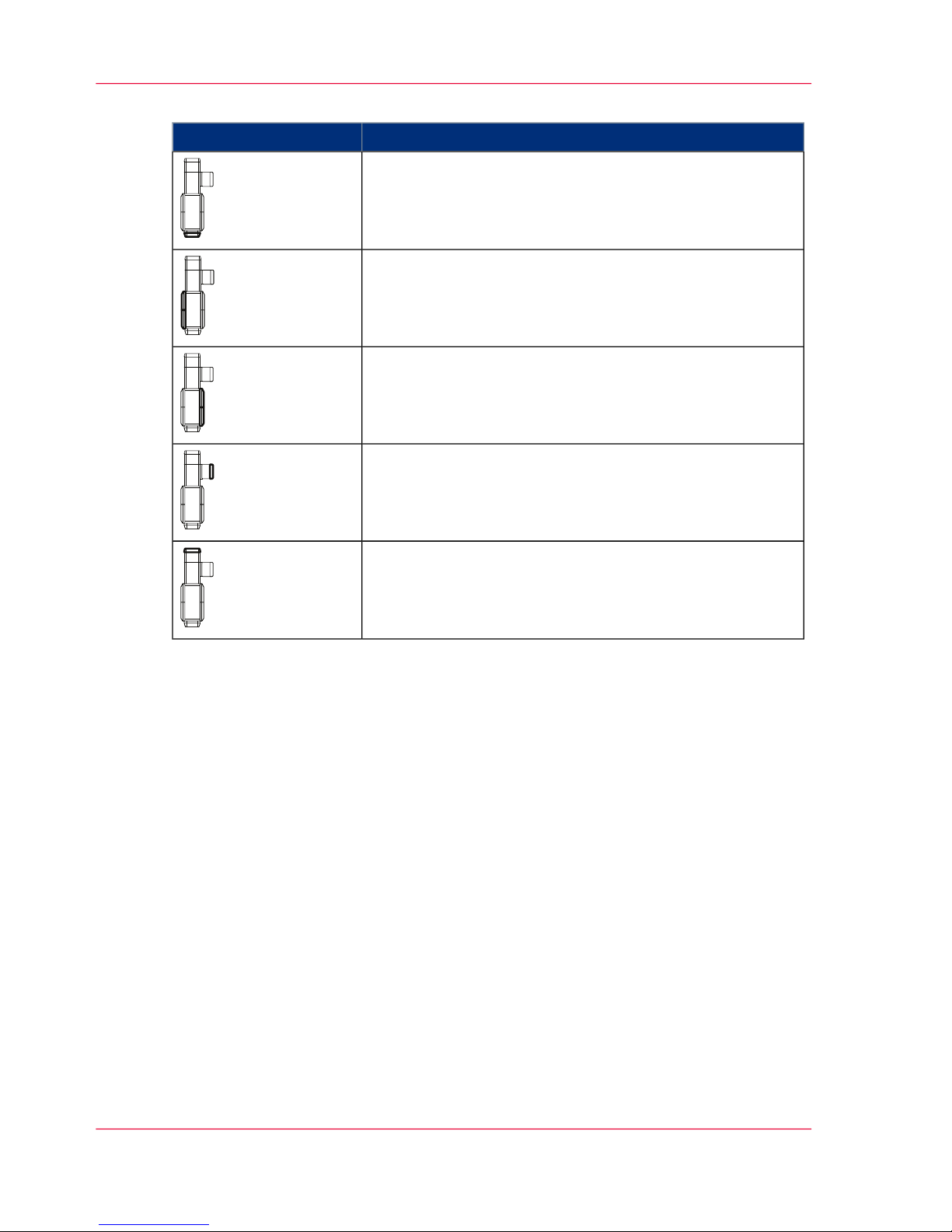
Legend
#
MeaningColor
These doors may be opened during printing without causing
any adverse effects. There is no danger, even if a door is open
Chapter 3 - Description of the Printing System54
Doors and Covers
Page 55

MeaningColor
These doors and covers must not be opened during printing.
To avoid any danger, the entire printing system shuts down if
they are opened.
With the optional toner supply using 1 kg (2.2 lb) toner bottles,
this door can be opened during printer operation without having
to disconnect the printer from the mains.
However, if highest levels of print quality are to be maintained,
we recommend that this door be left closed during printer operation.
Option
Paper path direction
Note:
Detailed information on opening and closing the doors is provided in the following
sections:
■
‘Opening Right Doors’ on page 157
■
‘Closing Right Doors’ on page 159
■
‘Opening Left Doors’ on page 161
■
‘Closing Left Doors’ on page 163
Chapter 3 - Description of the Printing System 55
Doors and Covers
Page 56

Internal View
Internal View — Overview
The Most Important Components
Note:
The figure shows the maximum configuration of the Océ ColorStream printing system
with five developer stations in the upper and lower print unit.
11 9105612
1 2 3 4 5 6 7
7
8
#
FunctionComponent / Designation
In the paper cooling system, the printed paper web
is cooled down to such an extent that it can be
processed further without problems.
Paper cooling1
In the smoothing module, the toner is optimally
bonded to the hot paper web, using smoothing
rollers.
Smoothing module2
‘Filter module’ on page 61Filter module3
Chapter 3 - Description of the Printing System56
Internal View — Overview
Page 57

FunctionComponent / Designation
In the fuser module, the toner is fused on the front
and rear sides of the paper by means of an infrared
lamp.
Fuser module/Infrared
lamp
4
In the print unit, the front and rear sides of the
paper are printed at the same time via the upper
and lower print units.
Print unit
Upper print unit
Lower print unit
5
‘Photoconductor unit’ on page 58Upper photoconductor
unit
Lower photoconductor
unit
6
‘Transfer unit’ on page 60Upper transfer unit
Lower transfer unit
7
The paper web is fed into the print module from
the external paper feed via the paper input.
Paper input8
The rocker is unlocked and opened to insert the
paper web.
Rocker9
Together with an external recooler, the heat ex-
changer keeps the temperature of the developer
stations constant.
Heat exchanger10
The paper web is fed into the vacuum unit of the
web buffer via the paper output.
Paper output11
#
The developer stations are filled with toner using
toner bottles of 6 kg (13.2 lb) each (see ‘Console’ on
page 62) or bottles of 1 kg (2.2 lb) each (optional).
Toner Feed Unit12
#
Paper web
Chapter 3 - Description of the Printing System 57
Internal View — Overview
Page 58

Photoconductor unit
Important Components of the Photoconductor Unit
The illustration shows a cross section of the photoconductor unit in the upper print unit
with five developer stations.
1
2
3
4
5
6
7
8
9
#
FunctionComponent / Designation
Exposes the negatively charged photoconductor
belt and neutralizes the charge in areas where toner
is afterwards to be applied.
LED print head1
Negatively charges the photoconductor belt.Charge corotron2
Cleans away toner residue on the photoconductor
belt.
Photoconductor blade3
Brushes away toner particles not transferred to the
transfer belt.
Cleaning brush4
Removes any residual charge on the photoconductor belt.
Cleaning corotron5
Chapter 3 - Description of the Printing System58
Photoconductor unit
Page 59

FunctionComponent / Designation
Maintains a constant level of toner for the toner
feed.
Toner box6
Measures the quantity of toner for each color.Toner mark sensor7
Applies toner to areas on the photoconductor belt
exposed by the LED print head.
Developer stations8
Establishes an image pattern for each color, fol-
lowed by a toner image.
Photoconductor belt (=
OPC belt = Organic
Photo Conductor belt)
9
Chapter 3 - Description of the Printing System 59
Photoconductor unit
Page 60

Transfer unit
Important Components of the Transfer Unit
The illustration shows a cross section of the transfer unit in the upper print unit.
1
2
3
4
#
FunctionComponent / Designation
Establishes the required potential difference on
the transfer roller point between the transfer belt
and paper by reversing the polarity of the toner
particles from negative to positive.
Transfer corotron
(only in the upper print
unit)
1
Collects the colored image patterns for individual
colors with register accuracy and then transfers
these together to the paper web.
Transfer belt2
Reverses the polarity of residual toner particles on
the paper after the transfer process back to negative
in preparation for cleaning.
Cleaning corotron3
Brushes away toner particles not transferred onto
the paper.
Cleaning brush4
Chapter 3 - Description of the Printing System60
Transfer unit
Page 61

Filter module
Important components of the filter module
#
DescriptionComponent / Designation
The waste toner, which is drained from the print
unit, is collected in the waste toner box.
Waste toner box1
The exhaust air is cleaned with a fine filter and
sent out of the top of the filter module.
Fine filter2
Chapter 3 - Description of the Printing System 61
Filter module
Page 62

Console
Important Components of the Console
1
2
4
3 54
#
DescriptionComponent
Screen1
Keyboard and mouse2
Storage for the user guide3
Toner supply4
Toner hoses on the printing system5
Color Allocation in the Console
The developer stations for all colors are supplied by a toner suction system consisting of
toner bottles weighing 6 kg (13.2 lb) each. For full-color printing systems, the developer
station slots for CMYK are predefined. In order to keep the toner suction hoses as short
as possible, the slots in the console are also predefined:
Chapter 3 - Description of the Printing System62
Console
Page 63

#
ColorSlot
Yellow1
Magenta2
Cyan3
Black4
CustomTone or additional black, cyan, magenta or yellow
toner bottles.
5/6
Note:
In the case of CustomTone printing systems, the color allocation in the console can be
changed by Service.
Chapter 3 - Description of the Printing System 63
Console
Page 64

Printing method
Introduction
The print image is created through an electrophotographic printing process with LED
print heads and two-component developers.
With a full color printing system, the colors are generated using the subtractive color
mixing technique, using the color separations cyan, magenta and yellow:
To reduce the coverage and achieve a greater depth with dark colors, black is also used
as the fourth color.
Printing Process
#
DescriptionLevel
The rastered controller pages are written to the photoconductor belt
with the LED print head.
■
During bilevel printing, each dot can be assigned either 100% color
or 100% white (= LED in LED print head on or off).
■
During multilevel printing, the light intensity of each LED can range
between 16 brightness levels. This dot modulation allows continuous
runs.
1
The developer station inks the image pattern.2
The inked image pattern is transmitted from the photoconductor belt
to the transfer belt.
3
Chapter 3 - Description of the Printing System64
Printing method
Page 65

DescriptionLevel
The photoconductor belt is cleaned.4
Transfer is from the transfer belt to the paper web. In double-sided print
operation, the upper and the lower printed page are transferred at the
same time.
■
Single color printing: Black/White Printing System
For single color printing, the inked image pattern is transferred from
the transfer belt to the paper web. The transfer roller point remains
swiveled onto the paper web and paper transport is not stopped.
■
Color collection mode: Full-color or CustomTone printing system
The colored image patterns for the individual colors are first collected
on the transfer belt and then transferred together to the paper web.
During the collection process, the transfer roller point is swiveled off
from the paper web and paper transport is stopped (Start/Stop operation).
5
Example: Color collection mode in a full color printing system with
CustomTone as the fifth color
The transfer belt is cleaned.6
The inked paper is fused to the paper via infrared radiation in the fuser
module (simultaneously for single and double-sided printing).
7
Chapter 3 - Description of the Printing System 65
Printing method
Page 66

DescriptionLevel
The paper is cooled in the paper cooling unit for further processing in
the paper post-processing unit.
8
Chapter 3 - Description of the Printing System66
Printing method
Page 67

Operating Elements
Operating Elements - Overview
The Most Important Operating Elements
1
1
1
2
2
3
4
5
#
DescriptionNumber
Additional operator panels1
Operator attention light2
On key3
Main switch4
Operator panel
Standard PC with screen, keyboard and mouse on external console
close to the printing system
5
Chapter 3 - Description of the Printing System 67
Operating Elements - Overview
Page 68

Note:
Additional operator panels can be used optionally. They do not have to be set up in
close proximity to the printing system. The access ticket ensures that parameters are not
set by different users at parallel operator panels.
Overview
You will find information on the following topics:
■
‘On key’ on page 69
■
‘Additional Operator Panels’ on page 70
■
‘Operator Attention Light (OPAL) — Overview’ on page 72
■
‘Operating elements in the printing system’ on page 77
Chapter 3 - Description of the Printing System68
Operating Elements - Overview
Page 69

On key
Display
#
FunctionKey
The printing system is on.
(green)
Transitional states
(flashing yellow)
The printing system is in standby mode (main switch is on).
(yellow)
The printing system is off.
(off)
Chapter 3 - Description of the Printing System 69
On key
Page 70

Additional Operator Panels
Three Key Operator Panels
Three additional identical key operator panels are located on the corners of the printing
system.
Function of the Keys
Note:
The function of the keys corresponds to the function of the buttons in the operator
panel toolbar (see ‘Buttons and Displays in the Left Area’ on page 84).
#
FunctionKey
Switches the printing system to ready for operation again from
the 'Stop' or 'Operator intervention necessary' statuses.
Requirements:
■
No errors present
■
Controller and system control are ready
Additional function: With the READY key, print operation
can also be interrupted to check the printed paper web (see
‘Checking the print image ’ on page 199).
READY
Moves the paper slowly forwards without fusing while the button is being pressed. The paper speed increases the longer you
press the button. However, synchronization is lost.
Requirement:
■
This function can only be executed in the 'Stop' status.
ADVF
(= ADVanced
Forward)
Chapter 3 - Description of the Printing System70
Additional Operator Panels
Page 71

FunctionKey
Moves the paper slowly backwards without fusing while the
button is being pressed. The paper speed increases the longer
you press the button. However, synchronization is lost.
Requirement:
■
This function can only be executed in the 'Stop' status.
ADVR
(= ADVanced
Reverse)
Moves the last printed pages out of the printing system with
the correct page alignment. Already printed pages will still be
fused. If required, the NPRO transport can be cancelled using
the 'Stop' key.
Requirement:
■
This function can only be executed in the 'Stop' status.
NPRO
(= Non Process
Run Out)
Transports the paper web forward at print speed while the
button is pressed. The paper web is not printed. Already printed
pages will still be fused.
Requirement:
■
This function can only be executed in the 'Stop' status.
EJECT
Moves the autofeed clamp to paper input position
or
Starts feeding the paper web into the printing system
AUTOFEED
Switches the printing system to 'Stop' status
or
Cancels a function that is running
STOP
Chapter 3 - Description of the Printing System 71
Additional Operator Panels
Page 72

Operator Attention Light
Operator Attention Light (OPAL) — Overview
Note:
For the Operator Attention Light (OPAL), Service can switch the flash concept between
the standard versions for bundle 11 and bundle 10. The following variants are preset:
■
ColorStream and 'VarioStream 9400 / 9500 / 9600 / 9700': Bundle 11 version
■
'VarioStream 9200': Bundle 10 version
Overview
You will find information on the following topics:
■
‘Operator Attention Light (OPAL)/Bundle 11 Version’ on page 73
■
‘Operator Attention Light (OPAL)/Bundle 10 Version’ on page 75
Chapter 3 - Description of the Printing System72
Operator Attention Light (OPAL) — Overview
Page 73

Operator Attention Light (OPAL)/Bundle 11 Version
Displays
The most important displays are summarized in the following table:
#
MeaningDisplay
The printing system is in standby mode.
(Main switch is on).
(off)
Print data is available; the printing process has started.
(green)
The printing system is in the 'Stop' or '... getting Ready' status.
(slowly flashing green)
The printing system is in 'Ready' or 'Energy saving mode ready'
status (if the fuser station has cooled down from the operating
temperature).
(flashing
green)
■
There is a warning in the 'Stop' status.
■
One of the 'Special functions' is being executed.
■
One of the 'NPRO', 'ADVF', 'ADVR', 'Eject' or 'Autofeed' keys
has been pressed.
■
A software update is being executed.
■
The printing system is being powered off.
(yellow)
There is a warning in the 'Ready' status.
(flashing yellow)
Chapter 3 - Description of the Printing System 73
Operator Attention Light (OPAL)/Bundle 11 Version
Page 74

MeaningDisplay
There is an error message.
(red)
The printing system has been stopped by the post print processing
unit (external stop). The printing system changes from the 'Ready'
status to the 'Stop' status after a preset amount of time.
(green/red)
Chapter 3 - Description of the Printing System74
Operator Attention Light (OPAL)/Bundle 11 Version
Page 75

Operator Attention Light (OPAL)/Bundle 10 Version
Displays
The most important displays are summarized in the following table:
#
MeaningDisplay
The printing system is in standby mode.
(Main switch is on).
(off)
The printing system is in the status
■
'Ready'
■
or 'Energy saving mode ready' (the operating temperature of the
fuser station has cooled down)
■
or in a transitional status.
(green)
Print data is available; the printing process has started.
(flashing
green)
The 'Ready' status indicates a "Toner empty" warning.
(flashing
green/yellow)
The 'Stop' status indicates a "Toner empty" warning.
(flashing
red/yellow)
One of the 'Special functions' is being executed
or the printing system is cooling down
or a software update is being executed (until restart).
(yellow)
Chapter 3 - Description of the Printing System 75
Operator Attention Light (OPAL)/Bundle 10 Version
Page 76

MeaningDisplay
The printing system is in the 'Operator intervention necessary' status.
(flashing red)
The printing system is not ready ('Stop' status)
or one of the 'NPRO', 'ADVF', 'ADVR', 'Eject' or 'Autofeed' keys
has been pressed
or the printing system is in a transitional status.
(red)
The printing system has been stopped by the post print processing
unit (external stop). The printing system changes from the 'Ready'
status to the 'Stop' status after a preset amount of time.
(green/red)
Chapter 3 - Description of the Printing System76
Operator Attention Light (OPAL)/Bundle 10 Version
Page 77

Operating elements in the printing system
Example
All operating elements for normal, incident-free printing operation are designed in bluegreen, e.g.:
Chapter 3 - Description of the Printing System 77
Operating elements in the printing system
Page 78

Paper specifications
General information
To ensure maximum system availability, the paper for the Océ ColorStream printing
systemmust comply with the applicable paper specifications and be stored in an environment with suitable ambient conditions.
Non-compliance with the paper specifications can cause damage to the printing system
and may also result in the release of substances from the paper that can contaminate the
environment or have a detrimental effect on health. Océ Printing Systems GmbHaccepts
no liability for such damages.
The printing system is designed to process a wide range of paper types. However, the
operational properties of the printing system and the print quality also depend on factors
such as:
■
Paper quality
■
Grammage
■
Moisture content
■
Dimensional stability
■
Smoothness, etc.
Before using new media, ensure that they comply with the paper specifications. If in
doubt, please contact the paper laboratory at:
Océ Printing Systems GmbH
Papierlabor
Postfach 1260
85581 Poing
Germany
Paper types
All media that comply with the requirements of the electrophotographic printing method
can be used in all specified formats and paper weights.
Using other paper qualities may result in reduced operational results, lower availability
and possibly also higher usage of consumables and expendables.
Paper handling
The climate (temperature and relative humidity) of the storeroom and processing room
is of major importance in ensuring optimum paper processing. Unsuitable conditions
Chapter 3 - Description of the Printing System78
Paper specifications
Page 79

can, for example, give the paper an excessive curl, make it bumpy, or alter its electrical
resistance.
Observe the following guidelines to ensure that the original high quality of the paper is
not impaired in any way.
■
Store the paper in its packaging until it is used.
■
Do not store paper on the floor or next to walls, or in the vicinity of water pipes, radiators, ventilators, windows (sunlight) etc.
■
Do not store paper in rooms in which the ambient conditions are subject to constant
change.
■
Before you use the paper, store it (in its packaging) near the printing system for a few
days if possible, or at least for 24 hours, to equalize temperature between paper and
room temperature.
■
Do not unpack more paper than you need.
■
Always use opened boxes of paper first. If you have to store open packs over a longer
period of time, cover the paper with protective film, so that no climate-related changes
occur.
Chapter 3 - Description of the Printing System 79
Paper specifications
Page 80

Chapter 3 - Description of the Printing System80
Paper specifications
Page 81

Chapter 4
Description of the Operator Panel
Page 82

Description of the Operator Panel — Overview
Description of the Operator Panel
This section describes the individual areas of the operator panel with the most important
menus, buttons and icons.
Overview
The operator panel is divided into the following areas:
Description
#
DescriptionArea
‘Toolbar — Overview’ on page 831
‘Menu Tree — Overview’ on page 912
‘Menu display’ on page 1043
Chapter 4 - Description of the Operator Panel82
Description of the Operator Panel — Overview
Page 83

A tool bar
Toolbar — Overview
Overview
The toolbar can be used to quickly access the important functions of the printing system
and to switch directly to frequently used menus.
Description
#
DescriptionArea
‘Buttons and Displays in the Left Area’ on page 841
‘Buttons and Displays in the Center Area ’ on page 862
‘Frame toolbar’ on page 903
Chapter 4 - Description of the Operator Panel 83
Toolbar — Overview
Page 84

Buttons and Displays in the Left Area
Function of the Buttons
Note:
The function of the buttons corresponds to the function of the keys on the printing
system's additional operator panels.
#
FunctionButton
Switches the printing system to ready for operation
again from the 'Stop' or 'Operator intervention necessary' statuses.
Requirements:
■
No errors present
■
Controller and system control are ready
'Ready'
Moves the paper slowly forwards without fusing while
the button is being pressed. The paper speed increases
the longer you press the button. However, synchronization is lost.
Requirement:
■
This function can only be executed in the 'Stop'
status.
'ADVF'
= ADVanced
Forward
Moves the paper slowly backwards without fusing while
the button is being pressed. The paper speed increases
the longer you press the button. However, synchronization is lost.
Requirement:
■
This function can only be executed in the 'Stop'
status.
'ADVR'
= ADVanced
Reverse
Moves the last printed pages out of the printing system
with the correct page alignment. Already printed pages
will still be fused. If required, the NPRO transport can
be canceled using the 'Stop' key.
Requirement:
■
This function can only be executed in the 'Stop'
status.
'NPRO'
= Non Process
Run Out
Chapter 4 - Description of the Operator Panel84
Buttons and Displays in the Left Area
Page 85

FunctionButton
Transports the paper web forward at print speed while
the button is pressed. The paper web is not printed.
Already printed pages will still be fused.
Requirement:
■
This function can only be executed in the 'Stop'
status.
'Eject'
Moves the autofeed clamp to paper input position
or
Starts feeding the paper web into the printing system
'Autofeed'
Switches the printing system to 'Stop' status
or
Cancels a function that is running
'Stop'
Display
#
FunctionDisplay
Gray background:
Indicates that currently no print data has been transferred from the
host.
'Data ready'
Green background:
Indicates that print data has been transferred from the host.
Gray background:
Standard display (no controller restart).
'System'
'Restart'
Red background:
Indicates that the controller is performing a restart.
If this display appears, the print data transmission from the host
must be repeated, as proper printing or fusing of the last pages is
no longer guaranteed against errors.
Chapter 4 - Description of the Operator Panel 85
Buttons and Displays in the Left Area
Page 86

Buttons and Displays in the Center Area
Buttons
#
FunctionButton
Switches to the buttons under 'Job control' in the 'Emulations' menu.
'Job control'
Switches to the 'Channels' menu.
The following buttons are available here:
Activates the channel, the printing system is online. The
connecting icon is closed.
Deactivates the channel, the printing system is offline. The
connecting icon is opened.
During the time required to activate or deactivate a channel,
the connecting icon is displayed in yellow.
'Channel control'
If a message was also transmitted by the data stream, this
icon is displayed.
Click here to switch directly to the 'Job preparation' tab in
the 'Job setup' menu. The complete message will be displayed there.
If there is a new message from another user, this icon is
displayed.
Click here to switch directly to the 'Notes' menu. All notes
or messages are displayed here.
Flashes when there is an error message.
Flashes when there is a warning.
Flashes when there is information.
When there is no error message, warning or information,
this button is hidden.
Clicking this button switches to the 'Errors and warnings'
menu.
Chapter 4 - Description of the Operator Panel86
Buttons and Displays in the Center Area
Page 87

FunctionButton
Indicates that remote access is activated. The Service center
can use this to perform remote diagnostics during print
operation.
Clicking the button deactivates remote access directly
without having to go through the menu.
Also indicates that remote Service diagnosis is activated. If
remote Service support was also activated, the remaining
time is displayed. One minute prior to automatic deactivation, the yellow display flashes to indicate that remote
support will shortly be deactivated.
Indicates that remote access is not activated.
Clicking the button activates remote access directly without
having to go through the menu.
Switches to the 'Consumable counter' menu.
In this menu, the current counter values and their respective
limit values are displayed for all consumables and expendables of the printing system.
Switches to the 'Service ticket' menu.
This menu displays all the data required to notify the relevant Service center.
'Service ticket'
Status displays
The current printer status is displayed on the centre of the toolbar. The individual status
displays have different background colors:
■
Green: The printing system is printing or is ready to print. If the printing of data integrity marks is turned off for the current configuration, an additional message to this
effect will appear.
■
Red: The printing system is stopped, operator intervention is necessary.
■
Gray: all other printer states
Status displays with green background
#
MeaningDisplay
The printing system is ready to print; there are no error
messages.
'Ready'
Chapter 4 - Description of the Operator Panel 87
Buttons and Displays in the Center Area
Page 88

MeaningDisplay
Normal print operation.
The set speed level appears in the menu 'Print speed' in
brackets.
'Printing' [%]
If necessary, process optimization is started by the device
control during print operation.
'Process optimization'
The printing system switches from the 'Stop' status to the
'Ready' status.
'... getting Ready'
Status displays with red background
#
MeaningDisplay
An error message is displayed. The error must be corrected,
otherwise printing cannot continue.
All current messages are also displayed in the 'Errors and
warnings' menu.
'Operator intervention
necessary'
Status displays with gray background
#
MeaningDisplay
The fuser station is cooling down.'Cool down'
The fuser station is heating up.'Warm-up'
The autofeed clamp is in insert position. The paper web
can be inserted.
'Autofeed: Insert paper'
The autofeed clamp has reached the paper output. The
paper web can be removed.
'Autofeed: Remove paper'
Paper web insertion has been started via the 'Autofeed' key.
The autofeed clamp is moved to the insert position.
'Autofeed: Started'
The autofeed clamp together with the paper web is transported to the paper output.
'Autofeed: Paper infeed'
The operating temperature of the fuser station has cooled
down.
'Energy saving mode
ready'
The printing system switches to the 'Stop' status.'Printing system stop-
ping'
The printing system is being initialized and is not yet ready
for printing.
'Initialization'
Chapter 4 - Description of the Operator Panel88
Buttons and Displays in the Center Area
Page 89

MeaningDisplay
The 'NPRO' key has been pressed. The last printed pages
are being moved out of the printing system. Pages that are
already printed will also be fused.
'Job advance'
The paper width sensor has detected that a paper web of a
different width has been inserted. Paper web stop plates are
being adjusted.
'Adjusting paper width'
The paper measurement routine has been started.'Paper measurement'
The 'ADVR' key was pressed; the paper web is being moved
backwards.
'Advance paper reverse'
The 'ADVF' key was pressed; the paper web is being moved
forwards.
'Advance paper forward'
The printing system is being prepared to power off. A shutdown setup is being written; all components are being exited.
'Powering off'
The 'Eject' key was pressed; the paper web is being moved
forward at print speed.
'Page advance'
A setup is being loaded or saved.'Setup'
Consumables are being replaced or the printing system is
being cleaned.
'Special functions'
The printing system is being prepared for printing.'Starting'
The printing system has stopped.'Stop'
The operating temperature of the fuser station has cooled
down.
'Energy saving mode
stop'
The printing system is powered on; device control is being
prepared.
'Preparation'
Printing is interrupted because the pre/post-processing unit
has stopped. The printing process will continue when the
pre/post-processing unit is ready again.
'Pre-/post-processing
not ready'
Display of error messages
As soon as an error occurs on the printing system, it is displayed within the status display
with black text on a white background. The same applies for warnings.
Chapter 4 - Description of the Operator Panel 89
Buttons and Displays in the Center Area
Page 90

Frame toolbar
Buttons
The buttons in the frame toolbar can be used to quickly access superordinate functions
for the complete printing stream and to switch directly to frequently used menus.
#
FunctionButton
Switches to the 'User profile' menu.
The language of the operator panel can be changed in this menu.
Indicates that the presently logged-on user possesses the access
ticket.
Clicking releases the access ticket directly without going through
the menu.
Indicates that the access ticket is released for other users.
Clicking requests the access ticket directly without going through
the menu.
Opens the Help window.
Switches to the 'Change user' menu.
Users can be registered or canceled in this menu.
Displays the user currently logged on.
Powers down the entire printing system if the 'Do you really want
to power off the printing system?' query is confirmed.
Changes from each sub-menu directly to the main menu of the
printing system or the Paper Path Manager.
Chapter 4 - Description of the Operator Panel90
Frame toolbar
Page 91

Menu Tree
Menu Tree — Overview
Note:
The menus displayed in the menu tree depend on the different rights for the individual
user categories.
This documentation describes all menu options normally set up for the user categories
"Operator" and "Key operator".
Information on the Paper Path Manager can be found in Help in the printing system
operator panel. Information on the Web Buffer can be found in Help in the printing
system operator panel and in the Océ Web Buffer user guide.
Main Groups
You can call all the menus through the menu tree. The menus are arranged into main
groups, e.g.:
■
[00] 'General'
You can define user settings valid for the entire print processing unit in these menus.
■
[02] 'ColorStream'
You can set the relevant parameters for the Océ ColorStream printing system in these
menus.
■
[BU] 'Web Buffer'
You can set the relevant parameters for the paper web buffer in these menus.
■
[FF] 'Paperpath Manager'
In these menus, you can gain an overview of all UP3I-capable devices of the print
processing unit.
■
[xx] Any additional device for paper pre-print processing and/or post-print processing.
The numbers before the main groups (= 'Paper sequence ID') are required to identify the
devices in the print processing unit.
Navigation
Clicking the switches in the menu tree lets you show or hide other menu levels, e. g.:
Chapter 4 - Description of the Operator Panel 91
Menu Tree — Overview
Page 92

You can switch directly to the main menu from any menu. Click the following button
in the toolbar for this purpose:
Overview
You will find information on the following topics:
■
‘'General' menus — overview’ on page 93
■
‘'ColorStream' Menus — Overview’ on page 97
Chapter 4 - Description of the Operator Panel92
Menu Tree — Overview
Page 93

'General' Menus
'General' menus — overview
Overview
You can define the user settings valid for the entire printing system in the 'General' menus.
Note:
Menus that can only be opened by the "Key Operator" user by default are shown in
bold in the table.
#
DescriptionMenu
The sub-menus contain the user settings relating to the Key
Operator.
'User management'
The sub-menus contain the user settings relating to the Operator.
'User'
The sub-menus contain security-related settings and displays.'Security'
Chapter 4 - Description of the Operator Panel 93
'General' menus — overview
Page 94

'User management' menus
Overview
Note:
The menus listed in the table can only be accessed by the"Key Operator" user.
The menus under 'User management' contain the user settings relating to the Key Operator.
#
DescriptionMenu
Add new users or user templates'Add user'
Delete users or user templates'Delete user'
Settings for:
■
Password
■
User rights for menus and elements
■
Language
'Edit user'
Chapter 4 - Description of the Operator Panel94
'User management' menus
Page 95

'User' menus
Overview
The menus under 'User' contain the user settings relating to the Operator.
#
DescriptionMenu
Log a user on or off'Change user'
Select the operator panel language and change the password'User profile'
Two different functions are combined into this menu:
■
Facilitate screen cleaning during printing
■
Also write an error log when the 'Operator trace' menu can
no longer be started.
'Tools'
Display of current error and warning messages and information
in the event that the printing system-specific menus and consequently the 'Errors and warnings' menu cannot be opened.
'Emergency display
for error'
Chapter 4 - Description of the Operator Panel 95
'User' menus
Page 96

'Security' menus
Overview
The menus under 'Security' contain security-related settings and displays.
#
DescriptionMenu
Requesting or releasing the access ticket for a specific operator
panel in the printing system.
'Access ticket'
Overview of the computer connected to the printing system.'Network management LAN A/LAN
B'
Display of any security violations.'Safety violations'
Chapter 4 - Description of the Operator Panel96
'Security' menus
Page 97

'ColorStream' Menus
'ColorStream' Menus — Overview
Display of Basic Information
The following basic information on the printing system is displayed in the 'ColorStream'
menu:
#
DescriptionDisplay
Number of all 12" pages previously printed in user operation
Further counters are displayed in the 'General counters' menu.
'User counter (total)'
Current print job
The job name will be displayed at the same time as data transfer
to the printing system occurs. As a maximum of 256 pages can
be saved in the page buffer, the job name will no longer be displayed some time before printing the last page.
'Print job:'
Currently loaded job setup'Job setup:'
Currently loaded color setup
The Color Setup Verification ID (CSVID) is displayed in addition to the name.
'Color setup:'
Description of the printing system'Printing system:'
Serial number of the printing system'Serial No.:'
Currently selected mode'Emulation:'
'ColorStream' Menus
The sub-menus contain all settings and displays relating to the Océ ColorStream printing
system.
'Displays' menus
The sub-menus contain displays on current error and warning messages and the various
counters on the printing system.
'Configuration' menus
The sub-menus contain the parameters relevant for setting the printing system.
Chapter 4 - Description of the Operator Panel 97
'ColorStream' Menus — Overview
Page 98

'Setup' menus
In setups, special settings for frequently recurring print requests can be grouped together
and saved. By loading a setup, the printing system can be configured quickly with the
right parameters for a print request.
If the printing system is powered up and it is not possible to load a setup, then the settings
from before the printing system was powered down continue to apply.
'Changing consumables' menus
The sub-menus contain the procedures for replacing consumables and expendables and
for cleaning the printing system. A menu for identifying the toner used is also available.
Chapter 4 - Description of the Operator Panel98
'ColorStream' Menus — Overview
Page 99

'Displays' menus
'Displays' menus
The sub-menus contain displays on current error and warning messages and the various
counters on the printing system.
'Errors and warnings' menu
Displays the current error and warning messages and information.
'General counter' menu
Displays page counters, warm-up time and user counters.
'Consumable counter' menu
Displays the current counter values and the relevant limit values for all consumables and
expendables for the printing system.
'Consumable history' menu
Displays replacement procedures for all replaced consumables and expendables, each with
time and counter reading.
'Notes' menu
Display and input of notes. The notes are stored for three months.
Chapter 4 - Description of the Operator Panel 99
'Displays' menus
Page 100

'Configuration' menus
'Configuration' menus
The sub-menus contain the parameters relevant for setting the printing system.
'Paper'
The sub-menus contain the parameters for the paper webs to be printed.
'Print parameters' menu
The sub-menus contain specific parameters for the printing system.
'Color' Menu
The sub-menus contain all parameters relevant for full-color, CustomTone or black-andwhite printing.
'Emulations' menu
Displays the emulations, and buttons for job control, restarting, and the PCL settings.
'Channels' menu
Display and setting of parameters for coupling the printing system to the network.
'Post-processing' Menu
The sub-menus contain the parameters for the post print processing marks.
Note:
The 'Mark extensions' menu is only displayed if a UP3I device is connected.
'Special functions' menu
The sub-menus contain the settings and displays for superordinate parameters and procedures for configuring and converting the printing system.
Chapter 4 - Description of the Operator Panel100
'Configuration' menus
 Loading...