

Oce Arizona T220 User Manual

Océ | Arizona T220
User Guide
Revision A • March, 2003

Océ Display Graphics Systems
© 2002 All Rights Reserved

Table of Contents
Preface
Copyright .................................................................iii
Current Document Version ......................................iii
Product Support, Documentation and Service ........iii
Product Compliance and Standards........................ v
1 T220 Product Overview
General Description................................................. 1
Safety Information ................................................... 4
Electromagnetic Compatibility .................................. v
Electrical Safety:....................................................... v
Product Safety:......................................................... v
Specifications ...........................................................1
Printer Power Requirements ....................................2
Vacuum Pump Power Requirements ....................... 3
Safety Labels............................................................6
2 Ink System Management
Océ Ink .................................................................... 9
Solvent..................................................................... 9
Changing an Ink Bottle .......................................... 10
Refilling the Solvent Bottle ..................................... 12
Emptying the Waste Bottle .....................................13
The Capping Station...............................................14
The Blotting Station ................................................15
Changing the Blotting cloth .................................... 15
The Pre-Fire Stripe.................................................17
Pre-Fire Stripe Catcher ..........................................17
Adjusting the Pre-Fire Stripe Catcher.....................17
3Media
Handling Media...................................................... 19
Recovering From a Carriage Crash ....................... 19
Thermal Expansion of Media..................................19
Media Holder Strips................................................20
3/10/03 i

Océ |
4 User Interface
Control Panel......................................................... 23
Key Pad, Display Screen and Status LEDs........... 24
Key Pad.................................................................. 24
Status Lights........................................................... 25
Online Screen......................................................... 25
Menu Structure ...................................................... 26
Print Queue Menu .................................................. 26
Operator Menu .......................................................26
Configure I/O Menu ................................................36
5 Operating the Arizona T220
Powering On and Off ............................................. 39
Printer Warm-Up.................................................... 40
Printing a Job......................................................... 41
Print Job Parameter Options .................................. 42
Print Job Settings ...................................................44
Using the Media Vacuum System ......................... 47
Maintaining Print Quality........................................ 48
Gradual Degradation in Print Quality......................48
Start of Day (Post-Maintenance) ............................ 48
Printing with High Heat...........................................48
Ineffective Drying at Start of Image ......................48
Banding ..................................................................49
Other Recommendations ....................................... 49
Evaluating the Diagnostic Stripe ............................ 50
Flushing the Heads ................................................54
6 Printer Maintenance
Maintenance Guidelines ........................................ 57
Who Should Do Maintenance?...............................57
Operator Maintenance Schedule............................57
Print Head Maintenance and Nozzle Recovery......58
Cleaning Solution Usage........................................58
Recommended Maintenance Frequencies............. 58
Daily Maintenance ................................................. 59
ii 3010100686
Weekly Maintenance .............................................63
Monthly Maintenance ............................................. 65
Bi-Yearly Maintenance ..........................................66

List of Figures
Arizona T220 Printer ........................................................1
Ink Station showing Ink Bottles ......................................10
Ink Station tray showing Solvent Bottle..........................12
Gantry Doors Open Showing Waste Bottle ....................13
Capping Station.............................................................. 14
Blotting Station ............................................................... 15
Mounting the Old Cardboard Core ................................. 16
Changing Blotting Paper ................................................ 16
Spit Catcher Adjustment ................................................ 18
Sheet of Foam Cor with 3 Media Hold-Down Strips.......20
Sharp edge of the strip butts up against the media.......21
Arizona T220 Control Panel ...........................................23
Key Pad, Display Screen, and Status LEDs ..................24
Maintenance Menu Tree ................................................ 27
Sample Nozzle Print....................................................... 30
Print Parameters Menu .................................................. 32
Units Menu ..................................................................... 33
Set Clock Menu.............................................................. 34
About Printer Menu ........................................................35
Configure IO Menu.........................................................36
AC Power Circuit Breaker Switch...................................39
T220 Printing Direction................................................... 46
Location of Vacuum Zones ............................................ 47
Detail From Diagnostic Stripe ........................................ 50
One Nozzle Not Firing Properly .....................................51
Five Adjacent Nozzles Not Firing ...................................51
Black Head Poorly Positioned........................................52
Poorly Operating Magenta Head....................................53
Removing Carriage Cover..............................................54
Syringing the Heads.......................................................55
3/10/03 iii

Océ |
iv 3010100686

Preface
0.1Copyright
© 2002 Océ Display Graphics Systems. All rights reserved.
This document contains information proprietary to Océ, to its subsidiaries, or to third
parties to which Océ may have a legal obligation to protect such information from
unauthorized disclosure, use or duplication. Any disclosure, use, or duplication of this
document or of any of the information contained herein for other than the specific purpose
for which it was disclosed is expressly prohibited, except as Océ may otherwise agree to in
writing. Due to continuing research and product improvements, features or product
specifications may change at any time without notice.
0.2Current Document Version
Copyright |
Date Doc. Number Revision Summary
03/05/03 3010100686 A Section to show electrical compliance.
Includes new pre-fire stripe catcher.
Revised maintenance section.
0.3Product Support, Documentation and Service
For further information on documentation and support for your Arizona T220 or for
information on other Océ Display Graphics Systems products, please contact:
Océ Display Graphics Systems
13231 Delf Place, #501
Richmond, British Columbia, Canada V6V 2C3
Phone: (604) 273-7730 Fax: (604) 273-2775
Web: http://www.dgs.Océ.com
FTP Site: http://www.cymbolic.com/ftp.html
Comments on this manual?
Please forward to the above address, marked Attention: Technical Writer.
Océ maintains a comprehensive support structure for its Arizona T220
customers. Upon
installation of your printer, you will be provided with the name of the sales and service office
responsible for your account. Record this information, along with the serial number of your
Arizona T220. Always report service problems to the office assigned to your account at
installation. Contacting the factory directly may cause unnecessary delays in resolving your
service issue.
3/10/03 -iii-

Océ |
US and Canadian Customers:
Océ Display Graphics Systems Service: 1-800-456-3473
13231 Delf Place, Building #501 Fax: 604-232-3154
Richmond, British Columbia, Canada Spares Orders: 1-800-295-6433 ext. 4
V6V 2C3
European Customers:
Océ Display Graphics Systems Service: 44 (0) 1628-519720
6 Waltham Park Service Fax: 44 (0) 1628-519589
Waltham Road Spares Enquiries: 44 (0) 1628-519736
White Waltham Spares Orders Fax: 44 (0) 1628-519751
Berkshire SL6 3TN
England
Asia Pacific Customers:
Océ Display Graphics Systems Service: 81-3-5472-3066
Grand Palace Tamachi 601 Fax: 81-3-5484-2071
4-9-18 Shibaura, Minato-ku
Tokyo, Japan 108-0023
Other:
Your regional distributor.
Customer Service Procedure:
When you call one of our customer service numbers you will be provided with telephone
technical support. Outside of office hours, you can leave a message and your call will be
returned the next working day. When you call, identify yourself as an Arizona T220
customer and provide the following information:
• The serial number of your Arizona T220
• Your company name and your name
• Your telephone number
• Nature of the problem
If we are unable to resolve your problem over the telephone, field engineers can be
dispatched to your site to conduct repairs. Service visits are paid for by the customer, either
under a maintenance agreement, by purchase order or prepayment. Time and material rates
are charged for any service not covered under a maintenance agreement. Before calling to
report a problem, gather as much information about the problem as possible and have it
ready to provide to the customer care center engineer. The more information you can
provide initially, the more quickly the problem can be corrected.
-iv- 3010100686-A

Product Compliance and Standards |
0.4Product Compliance and Standards
0.4.1Electromagnetic Compatibility
This equipment generates, uses and radiates radio frequency energy and if not installed and
used as designed or intended, may cause interference to radio communications. This
equipment has been tested and found to comply with the limits for a Class A computing
device. This equipment has been designed to provide reasonable protection against such
interference when operated in residential and commercial environments. Operation of this
equipment in a residential area may cause interference, in which case the user, at his own
expense, is required to take whatever measures are required to correct the interference
0.4.2Electrical Safety:
North America:
CSA 60950-00 and UL 60950-2000 )
European Community:
EN60950
EN60204-1 Low Voltage Directive 73/23/EEC
0.4.3Product Safety:
TUV EN 292-2:1996+A1
EN60950:1992+A1+A2+A3+A4+A11 Low Voltage Directive 73/23/EEC
EMC:
This device complies with Class A emission limits in accordance with:
EMC Directive 89/336/EEC
EN61000-6-2:2000
EN61000-6-4:2000
FCC Part 15:2001
3/10/03 -v-

Océ |
-vi- 3010100686-A
1 T220 Product Overview
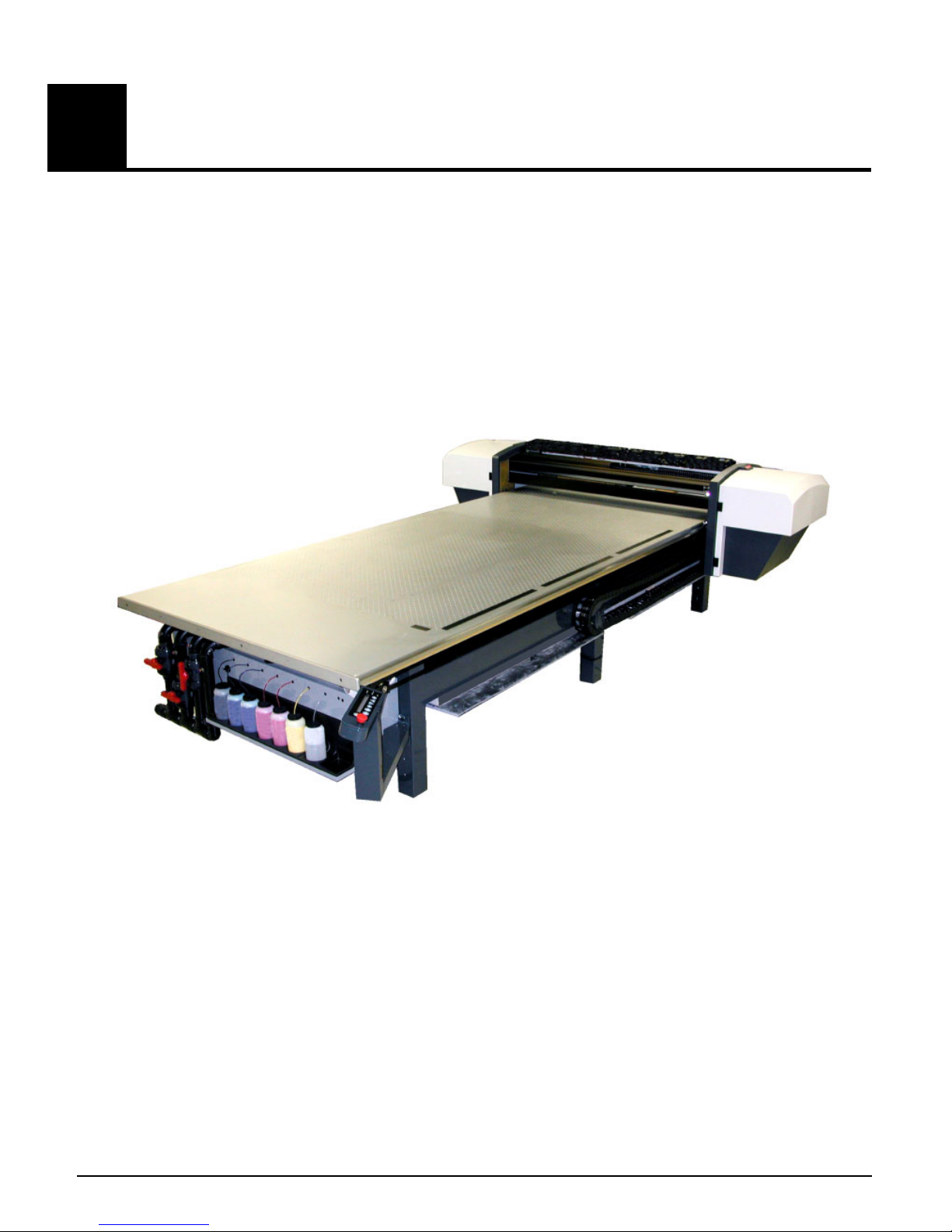
1.1General Description
The Arizona T220 is a six color digital inkjet printer capable of producing large format
images on various rigid and flexible stock materials. The printer consists of a large
vacuum table and moving gantry. The material is held flat and stationary on the
vacuum table during printing. Printing occurs as the gantry moves from one end of the
table to the other. The printer uses solvent-based inks. An infrared heater attached to
the gantry provides curing of the ink on the media. The Arizona T220 must be operated
in accordance with certain environmental and safety reqirements noted in this
document.
1.1.1Specifications
Printhead Technology: .................Piezoelectric (504 nozzles per color)
Colors: .........................................Black, Cyan, Light Cyan, Magenta, Light
Ink: ...............................................Océ Display Graphic Systems 2200
Resolution: ...................................309 dpi
3/10/03 1-1
Figure 1 Arizona T220 Printer
Magenta, Yellow
solvent-based pigment Ink

Océ | T220 Product Overview
Throughput: ................................. 4 Pass Mode - Up to 165 sq. feet (15.33 sq.
meters) per hour
8 Pass Mode – Up to 90 sq. feet (8.36 sq.
meters) per hour
Max. Media Size: ......................... 62” wide x 120” long x 2” thick
Max. Print Size: ........................... 62.5” wide x 120.5” long
Printer Dimensions: ..................... Table – 70.5” x 168”
Gantry – 36” x 120”
Weight: ........................................ 1700 lbs
Air Requirement: Pressure: ......... 80 to 100 psi min.
Flow: 1cfm min.
Air supplied to the printer must pass through an Air Preparation Unit that contains the
following:
Air Filter – 5 micron element c/w auto drain;
Coalescing Filter – 99.97% efficiency c/w auto drain; and
Regulator c/w gauge.
1.1.2Printer Power Requirements
The printer operates in the following two configurations.
Delta (USA) Configuration:
Voltage:......................230VAC +/-10%, 3 Phase
Frequency:.................47 to 63 Hz
Current:......................24AMPS maximum steady state
Power: ....................... 15kW max.
Circuit Breaker...........30 Amps
Wye (European) Configuration:
Voltage:......................400VAC +/-10%, 3 Phase
Frequency:.................47 to 63 Hz
Current:......................24AMPS maximum steady state
Power: ....................... 15kW max.
Circuit Breaker...........30 Amps
1-2 3010100686-A

General Description |
1.1.3Vacuum Pump Power Requirements
The vacuum pump operates over the following range of voltages and frequencies:.
230 Volts @ 60HZ
Voltage:......................230 VAC +/-10%, 3 Phase
Current:......................14 AMPS maximum steady state
Power: .......................7kW max.
Circuit Breaker...........20 Amps
400 Volts @ 60Hz
Voltage:......................400 VAC +/-10%, 3 Phase
Current:......................7 AMPS maximum steady state
Power: .......................7kW max.
Circuit Breaker...........15 Amps
190 Volts @ 50 Hz
Voltage:......................190 VAC +/-10%, 3 Phase
Current:......................16.5 AMPS maximum steady state
Power: .......................7kW max.
Circuit Breaker...........20 Amps
380 Volts @ 50 Hz
Voltage:......................380 VAC +/-10%, 3 Phase
Current:......................8 AMPS maximum steady state
Power: .......................7kW max.
Circuit Breaker...........15 Amps
ODGS recommends that the AC power outlet for the vacuum pump be located within 8
feet of the power inlet on the pump.
Important: Unplugging the power cord from the wall socket is the only way to
isolate the entire machine.
3/10/03 1-3

Océ | T220 Product Overview
1.2Safety Information
MSDS
Read and practice safety guidelines as outlined in the Material Safety Data Sheet
(MSDS) for each ink. Post the document in the work area as required by prevailing law.
MSDS for all six inks and the CGS80 solvent are available via the Internet.
1. Go to www.3m.com
2. Click on Search, MSDS
3. Select 3M ID Number
4. Enter one of the following 11 digit numbers:
• 75-3470-3042-3 T2295 Black
• 75-3470-3043-1 T2296 Cyan
• 75-3470-3039-9 T2286 Light Cyan
• 75-3470-3040-7 T2291 Magenta
• 75-3470-3038-1 T2281 Light Magenta
• 75-3470-3041-5 T2292 Yellow
• 75-3465-0408-9 CGS80 Solvent
Note: These numbers are printed on the cardboard box for the ink and on the ink
bottles themselves.
Personal Safety
The operator should wear butyl rubber gloves, a protective apron, an NIOSH-approved
respirator (half-mask organic vapor respirator), and Safety glasses with side shields
when handling inks.
Risks Associated with Handling Inks
The Arizona T220 uses solvent-based inks; the liquid and the fumes are combustible.
The inks may cause eye irritation or skin irritation upon prolonged or repeated contact.
The inks may be absorbed through the skin, and may cause respiratory system irritation
and nervous system impairment.
1-4 3010100686-A

What to do with Ink Spills on Surfaces
Observe precautions as noted above, then:
a) Ventilate the area;
b) Contain the spill;
c) Cover with absorbent material;
d) Collect spilled absorbent material;
e) Place in a closed container;
f) Clean up residue with water (do not release to waterways or sewer);
g) Incinerate in a permitted hazardous waste incinerator.
What to do with Ink Spills on Persons
Safety Information |
• Eye contact: immediately flush eyes with large amounts of water. Get
immediate medical attention.
• Skin contact: flush skin with large amounts of water. If irritation persists,
get medical attention.
• Inhalation: remove person to fresh air. If not breathing, get immediate
medical attention and give artificial respiration. If breathing is difficult, get
immediate medical attention.
• If swallowed: call a physician immediately. Only induce vomiting at the
instructions of a physician. Never give anything by mouth to an
unconscious person.
IR Heater
Two infared heaters mounted on the gantry are used to dry the ink during printing. Each
heater has two 3kw elements. The printer uses 3 of the 4 possible elements thus
providing a maximum of 9kw of heat. The carriage passes under the heater and has a
protective cover that reflects heat. The heater operates automatically and does not
require operator intervention.
Caution:
Keep hands clear of the heater assembly. This area will be hot during
and right after printing.
3/10/03 1-5
Océ | T220 Product Overview
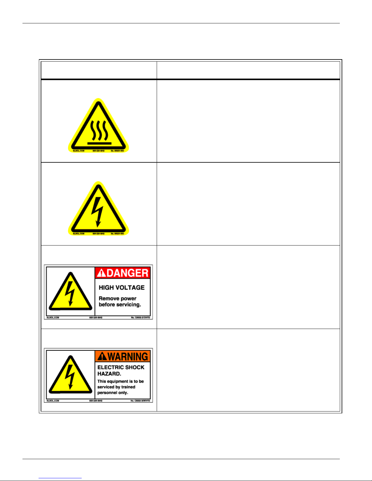
1.2.1Safety Labels
Table 1 Safety Labels
Label Description
Burn Hazard
Shock Hazard
Located on the heater assembly at the Home
end of the gantry. Entire gantry area is hot
during and after printing.
Located on the heater assembly at the Home
end of the gantry. Area is heated by electricity
and is a potential shock hazard.
DANGER High Voltage Remove power before servicing
Located inside the electronics enclosure. AC
power cable should be disconnected before
servicing any electrical components.
Electric Shock Hazard This equipment is to be serviced by
trained personnel only
Located on the door to the electronics
enclosure. This door must be kept locked and
only opened by a trained technician.
1-6 3010100686-A

Safety Information |
Table 1 Safety Labels
Label Description
Voltage Warning Before connecting Power Supply Cord to the unit,
Befor e connecting Power
Supply Cord to the unit, refer
to the installation instruction
to determine proper In put
!
Voltage Configuration.
refer to the installation instruction to determine
proper Input Voltage Configuration.
See Technical Service Manual Part 2
“Installation and Setup”.
Grounding Warning WARNING HIGH LEAKAGE CURRENT EARTH
CONNECTION ESSENTIAL BEFORE
WARNING
CONNECTING SUPPLY.
!
Pinch Point
Crush Hazard
Located above the AC power cable.
Located on the bracket endplate and the plateend cap.
Located on the gantry end covers.
3/10/03 1-7

Océ | T220 Product Overview
Table 1 Safety Labels
Label Description
Danger Crush Hazard Keep hands clear while operating.
Warning Moving Gantry German Translation:
Lock out power before servicing.
Located on the endplate of the gantry where
the carriage rests on the capping station.
WARNUNG
BEWEGLICHE MASCHINENTEILE
Located on the table to identify the risk
involved with the gantry moving during
printing.
1-8 3010100686-A
2 Ink System Management
2.1Océ Ink
The Arizona T220 uses solvent-based pigmented inks including Cyan (C), Magenta
(M), Yellow (Y), Black (K), Light Magenta (LM), and Light Cyan (LC). The ink is
supplied in 0.95 liter (32 ounce) bottles. The Océ ink part numbers, which are
necessary for ordering more ink, are provided in the following table:
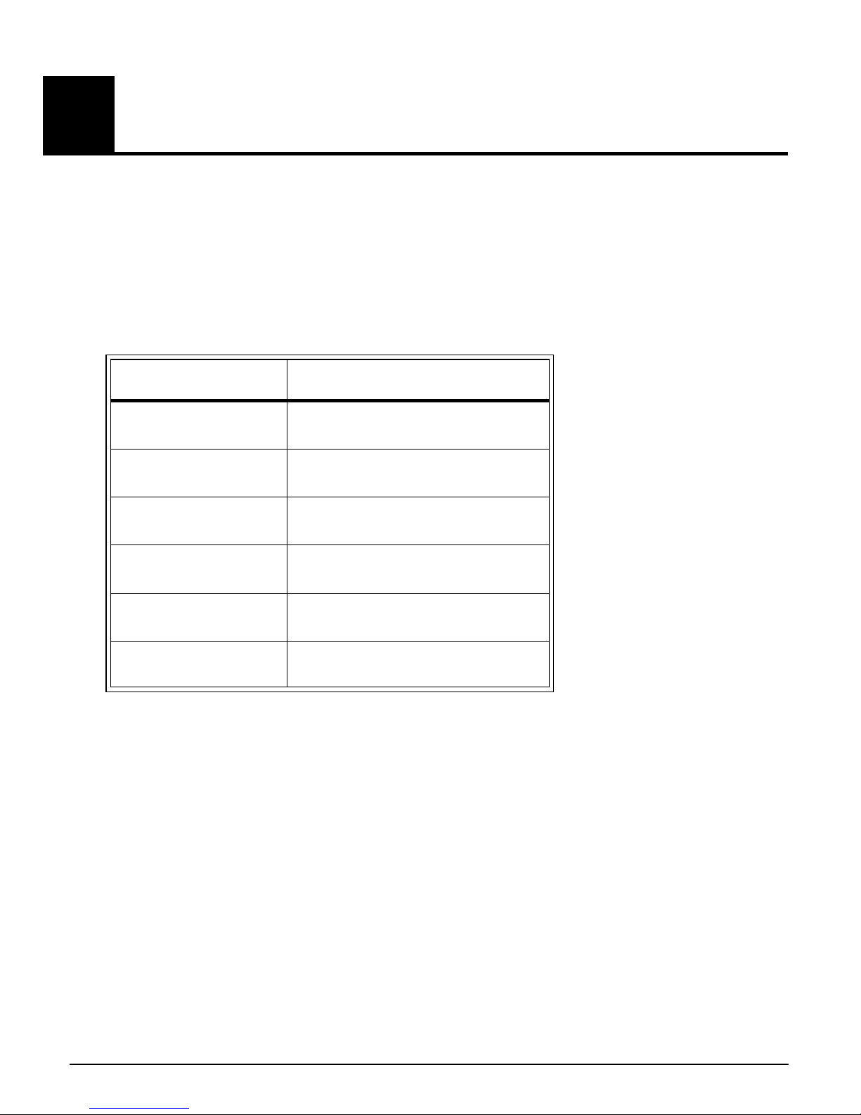
Table 2
Ink Océ Part #
Black
Cyan
Magenta
Yellow
Light Cyan
Light Magenta
2.2Solvent
3012000180
3012000181
3012000182
3012000183
3012000184
3012000185
The T220 use CGS 80 (part #3000-0057) solvent as a maintenance solution.
Important: See “Safety Information” on page 4 before handling solvent or ink.
3/10/03 2-9
Océ | Ink System Management
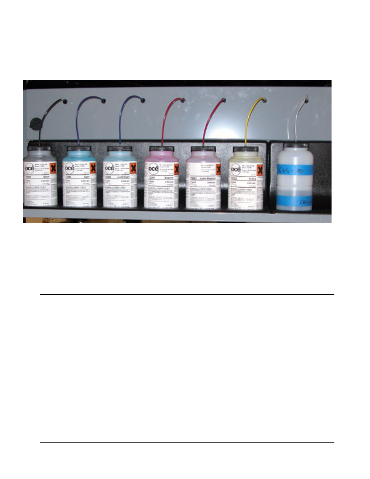
2.3Changing an Ink Bottle
The ink bottles are located on the Ink Station tray. Ink levels for each bottle are
monitored by sensors. Low ink levels are indicated on the control panel.
Figure 2 Ink Station showing Ink Bottles
Important: To reduce the chance of poor image quality, do not shake the ink supply
bottles before installation or during printing. This may introduce air
bubbles into the ink supply system.
When the control panel displays an “XXX ink low” message, that particular ink should
be replaced. Ink can be replaced at any time, with one exception — Do NOT replace inks
immediately after a purge since the ink pumps may be activated at that time. To replace
an ink bottle:
1. Unscrew the lid on a new ink bottle and remove the silver sealing foil;
2. Unscrew the lid on the empty ink bottle and unplug the coupler. Note that the lid
stays attached to the ink line and coupler. Put the old bottle aside and immediately
place the coupler into the new ink bottle by pushing the flange all the way into the
ink pick-up insert;
Important: Ensure that the coupler is fully inserted into the ink pick-up insert to
prevent air being drawn into the ink line when the pump is on.
2-10 3010100686-A

Changing an Ink Bottle |
3. Place the attached lid on the new ink bottle and screw it on tightly;
Caution:
Do not use the residual ink to top up the ink in another bottle as this
will introduce contaminants that collect at the bottom of the bottle.
4. Dispose of the used ink in an environmentally friendly manner.
Warning:
Océ Display Graphics Systems accepts no liability when non-Océ ink
is used. Customers using non-Océ ink assume all risk of damage that
might result. Customer agrees to waive any claims or rights they may
otherwise have against Océ Display Graphics Systems or its agents for
damage and/or loss of business resulting from use of non-Océ ink.
5. Press ACCEPT on the control panel to enter the type of color and begin printing.
3/10/03 2-11
Océ | Ink System Management
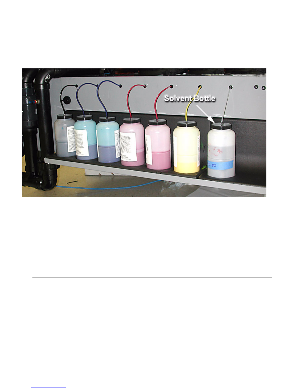
2.3.1Refilling the Solvent Bottle
Solvent is used to maintain the capping station. The solvent supply bottle is located on
the end of the ink station tray, to the right of the ink bottles. A sensor monitors the
solvent level in the bottle. A low solvent level causes a message to display on the control
panel.
Figure 3 Ink Station tray showing Solvent Bottle
Refill the solvent bottle when the control panel indicates the solvent is low. Top up the
solvent bottle if the printer is to be left unattended longer than overnight. To refill the
solvent bottle:
1. Unscrew the lid and remove the coupler. Remove the solvent bottle from the Ink
Station Tray before filling. This prevents spilling of solvent on the painted metal
surfaces or the solvent level sensor;
Note: Tapping the sides of the lid on a new 1 gallon solvent container will ease the
removal of the lid.
2. Place the funnel (Part #3010100404) into the off-center hole in the ink pick-up
insert inside the solvent bottle and fill the solvent to the level of the shoulder on the
bottle.
3. Set the bottle on the tray and replace the coupler by inserting it fully into the hole in
the lid. Screw the lid back on securely.
2-12 3010100686-A
Changing an Ink Bottle |
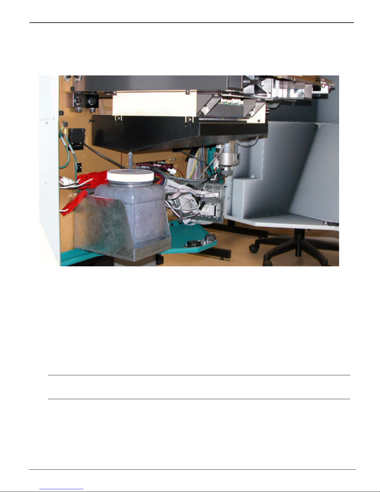
2.3.2Emptying the Waste Bottle
The printer accumulates waste that is made up of ink and solvent. The waste bottle is
located in the right side of the gantry beneath the capping station. A sensor monitors the
waste level in the bottle, and a high level is reported on the control panel.
Figure 4 Gantry Doors Open Showing Waste Bottle
The waste bottle should be emptied when the control panel indicates that the waste bottle
is almost full. To empty the waste bottle:
1. Remove the drainage tube from the lid of the waste bottle;
2. Remove the waste bottle from the bracket and pour the waste into a suitable
container for disposal. Dispose of waste in accordance with local laws or as directed
in the MSDS sheets — See “Safety Information” on page 4.
Note: If you need to replace the waste bottle container with a new one, or if you
require a spare bottle, order part # 3010100266.
3. Replace the empty container by fitting it into the bracket;
4. Ensure that the lid is securely screwed on to the waste bottle and finally re-insert the
drainage tube.
3/10/03 2-13
Océ | Ink System Management
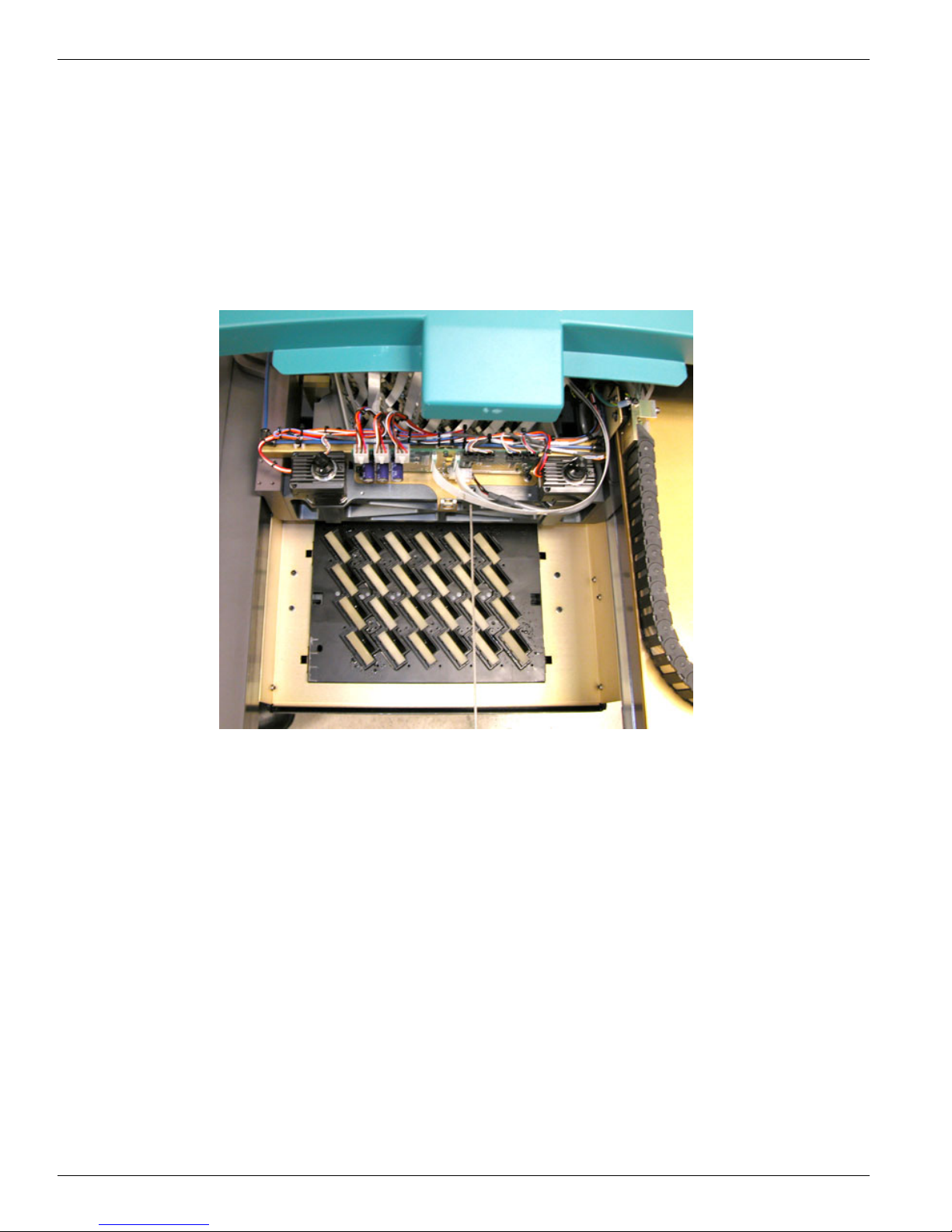
2.3.3The Capping Station
The capping station is located in the right end of the gantry. The function of the capping
station is to prevent the printheads from drying out when not in use. The capping station
is essentially a tray supporting 24 solvent saturated foam pads, one for each printhead.
The tray also provides drainage for excess ink and solvent. Excess ink and solvent are
collected under the capping tray and funneled into the waste bottle. While capped, each
printhead’s nozzle plate comes in contact with a solvent-saturated foam pad. Solvent is
automatically pumped up to the tray at regular intervals to ensure all the pads are suitably
soaked.
Figure 5 Capping Station
2-14 3010100686-A
 Loading...