

Oce Arizona 600 User Manual

Using ColorBlend six-color printing technology
Océ | Arizona 600
User Manual
Revision E • December 9, 2004

Océ Display Graphics Systems
© 2004 All Rights Reserved

Copyright and Trademarks
0.1Copyright and Trademarks
© 2004 Océ Display Graphics Systems. All rights reserved.
This document contains information proprietary to Océ, to its subsidiaries, or to third
parties to which Océ may have a legal obligation to protect the information from
unauthorized disclosure, use, or duplication. Any disclosure, use, or duplication of this
document or of any of the information contained herein for other than the specific purpose
for which it was disclosed is expressly prohibited, except as Océ may otherwise agree to in
writing. Due to continuing research and product improvements, features or product
specifications may change at any time without notice.
Arizona 600 is a trademark of Océ Display Graphics Systems. ColorBlend is a registered
trademark of Océ Display Graphics Systems. PosterShop is a registered trademark of Onyx
Graphics, Inc.
Plexiglas is a registered trademark of Röhm GmbH & Co.
trademark of Centronics Data Computer Corp.
Teflon is a registered trademark of E.I. DuPont Corp.
0.2Current Document Version
Date Release Doc. Number Revision Summary
04-09-04 Initial 3012001919 A Engineering Services/
05-12-04 First
Revision
06-30-04 Second
Revision
Same B Var iou s up da te s an d
Same C Additional information and
Centronics is a registered
Technical Publications
corrections
corrections, including
additional printer
maintenance (Chapter 5)
12/9/04 iii
Océ|Current Document Version
Date Release Doc. Number Revision Summary
11-19-04 Third
Revision
12-09-04 Fourth
Revision
Same D Information about 440-series
inks, maximum image width
specification change,
cancellation of printing in
Print & Go mode (Firmware
3.2 or higher), halogen lamp
temperature control menu
with Other media (Firmware
3.2 or higher), and additional
minor corrections
Same E Additional maximum image
width specification change,
halogen lamp temperature
control change (Firmware
3.3 or higher), added
warning to not access the
carriage during printing
iv

Product Support and Documentation
0.3Product Support and Documentation
For further information on the Arizona 600 printer or for information on other Océ Display
Graphics Systems products, please contact:
Océ Display Graphics Systems
2811 Orchard Parkway
San Jose, CA 95134
U.S.A.
Phone: 408-232-4000
Fax: 408-232-4100
0.3.1Comments on this manual?
Please forward to the above address, marked Attention: S & S Department.
0.4Arizona 600 Printer Warranty
Contact your Customer Service representative for information about your warranty.
0.5Annual Maintenance Agreement
Océ Display Graphics Systems recommends the purchase of an Annual Maintenance
Agreement to ensure optimum performance, the highest quality prints, and highest reliability.
Please contact your Océ service manager for more information.
The supplies used in the Arizona 600 printer must meet Océ Display Graphics Systems
qualifications and must be purchased from Océ Display Graphics Systems or its authorized
agent. The use of any unauthorized ink and/or media is not supported by Océ Display
Graphics Systems and may invalidate the Arizona 600 printer Warranty and/or Maintenance
Agreement. If unauthorized supplies are used, Océ Display Graphics Systems reserves the right
to charge the customer to restore the printer to the operating condition in which it left the
factory.
0.6Ordering Printer Supplies
Océ Display Graphics Systems works closely with the manufacturers of imaging media to
characterize the properties that work best with ink and media used by Océ Display Graphics
Systems printers. Océ Display Graphics Systems supplies are extensively tested in our
laboratory before being approved for shipment to our customers.
Océ Display Graphics Systems recommends that you use only approved supplies. Contact
your local representative for information about ordering supplies.
12/9/04 v

Océ|Ordering Printer Supplies
vi

Table of Contents
1 Product Overview
Table of Contents
Product Description..........................................1-1
Unique Features .............. ... ... .... ... ... ... .... ... ... ..1-1
Operator Requirements....................................1-4
Consumable Supplies.......................................1-4
Cleaning Supplies...........................................1-4
Switching On or Off ..........................................1-5
Precautionary Measures...................................1-5
Arizona 600 Technical Specifications...............1-7
Components Reference....................................1-9
Safety Information ............................................1-9
2 Ink System
Handling Inks....................................................2-1
Ink Supply Tray...............................................2-1
Cleaning Fluid or Capping Fluid and
Waste Bottles .........................................2-2
Ink Supply Changes .........................................2-2
Ink Filter Changes ............................................2-4
3 Media System
Media Specifications.........................................3-1
Media Handling.................................................3-1
Opening the Door................................ .... ... ... ..3-2
Closing the Door.............................................3-2
Media Support System............................... ... ..3-2
Mandrel Assembly ........... ... ... .... ... ... ............... 3-4
Roll-to-Roll Media Installation...........................3-5
Installing Supply Media...................................3-5
Loading New Supply Roll ... ... .... ... ... ... .... ... ... ..3-8
Take-up Roll Reattachment..........................3-16
Print & Go Media Installation..........................3-17
12/9/04 vii
Installing Supply Media.................................3-18
Loading New Supply Roll. ... ... .... ... ... ....... ... ...3-18
EMTU Take-up Roll Reattachment...............3-28

Océ|Table of Contents
4 Control Panel
Overview...........................................................4-1
Control Panel Buttons.....................................4-1
Cancel Printing ...............................................4-3
Status Lights...................................................4-3
Navigating from the Main Menu........................4-4
Copies/Reprints................................................4-4
Reprint Copies of a Previously Printed
Image......................................................4-4
Operator ...........................................................4-5
Print Parameters.............................................4-6
Test Prints . .... ... ... ... ... .... ... ...............................4-8
Maintenance .................................................4-13
Media Menu..................................................4-20
About Printer.................................................4-25
Units..............................................................4-26
Set Clock ............ ... ... .... ... ... ... .... ... ... ............. 4-27
Ink Menu.........................................................4-28
Ink Bottle Installation . .... ... ... ... .... ... ... ... .... ... ...4-28
Configure I/0...................................................4-31
Parallel Port Configuration............................4-31
LVD-SCSI-3 Port Configuration....................4-31
5 Printer Maintenance
Maintenance Guidelines...................................5-1
Cleaning Fluid/Capping Fluid Usage ..............5-1
Print Head Maintenance and Nozzle
Recovery ......................................................5-1
Operator Maintenance Schedule......................5-2
Automated Maintenance...................................5-4
Operator-Performed Maintenance....................5-5
Waste Bottle Full........................ ... ... ... .... ... ... ..5-5
Cleaning Fluid/Capping Fluid Empty...............5-5
Cleaning the Media Drive Roller... ... ... .... ... ... ..5-5
Capping Station Maintenance.........................5-8
Maintenance Cloth Station .............................5-11
viii
Blotting Cloth Installation ..............................5-11
Carriage Cable ...............................................5-16
Adjusting the Carriage Cable........................5-16
Cleaning the Carriage Cable.........................5-17
Printer Filters..................................................5-18

Purolator Hi-40 Filters...................................5-18
Air Pressure Pump Line Filter.... ... ... ... .... ......5-19
6 Error Messages and Troubleshooting
Overview...........................................................6-1
User-Correctable Errors..................................6-1
If Problems Persist........................... ... .... ... ... ..6-2
Calling for Service...........................................6-2
System Errors...................................................6-3
A Menus
B Printer Maintenance
Materials.......................................................... B-1
Cleaning Fluid/Capping Fluid Usage ............. B-1
Material Usage............................................... B-2
General Recommendations for the Operator .. B-2
Cleaning the Capping Station.......................... B-2
Cleaning the Carriage Face Plate ................... B-3
Cleaning the Print Head Nozzle Plates ........... B-3
Table of Contents
Flushing a Print Head...................................... B-5
C Printer Features Description
Blotting Cloth Usage........................................ C-1
Optimal versus Wide Writing Gap – Default
“Optimal”...................................................... C-1
Conserve Media – Default “ON”......................C-1
Feed Adjustment – Default “0”......................... C-2
Condition Media – Default “OFF”.....................C-2
D Two-Sided Printing and Double Print
Two-Sided Printing..........................................D-1
Double Print..................................................... D-1
Preparing the Arizona 600 Printer..................D-1
Marking the Platen.........................................D-1
12/9/04 ix

Océ|List of Figures
List of Figures
Figure 1-1 Print & Go Roller or Mandrel Holder...........1-3
Figure 1-2 Circuit Breaker Switch Location..................1-5
Figure 1-3 Battery Back-up Option...............................1-6
Figure 1-4 Clearance Requirements (Footprint)...........1-9
Figure 2-1 Ink Tray (1-Gallon Bottles Shown)..............2-1
Figure 2-2 Cleaning Fluid or Capping Fluid
Figure 2-3 Supply Ink...................................................2-3
Figure 2-4 Scanning the Ink Barcode...........................2-3
Figure 2-5 Remove the Top Tube from the Old Filter...2-4
Figure 2-6 Attach Tube to the New Filter......................2-5
Figure 2-7 Allow the Ink to Drain from the Filter
Figure 2-8 Moving the Supply Tube from the Bottom
Figure 3-1 Left Clip Closed...........................................3-2
Figure 3-2 Left Clip Open.............................................3-2
Figure 3-3 Media Support System and Installing
Figure 3-4 Mandrel Assembly.......................................3-4
Figure 3-5 Mandrel/Media Assembly on the
Figure 3-6 Secure the Mandrel/Media Assembly.........3-6
Figure 3-7 Loading Mechanism Lock Lever
Figure 3-8 Loading Mechanism Lock Lever
Figure 3-9 Feeding Media Over the Platen ..................3-8
Figure 3-10 Pinch Roller Handle ..................................3-9
Figure 3-11 Feeding Media Over the Drive Roll...........3-9
Figure 3-12 Wrap Media Around the
Figure 3-13 Align and Tape the Media.......................3-10
Figure 3-14 Rotate the Take-up Core.........................3-11
Figure 3-15 Cutting Media Above
Figure 3-16 Media Routing.........................................3-19
Figure 3-17 Media Edges Aligned..............................3-20
Container and Waste Container..............2-2
into the Supply Bottle...............................2-5
of the Old Filter to the New Filter.............2-6
Media on the Mandrel..............................3-3
Support Arms...........................................3-5
in the Correct Position.............................3-7
Out of Position.........................................3-7
Take-up Core.........................................3-10
Take-up Dancer ....................................3-16
x

List of Figures
Figure 3-18 Open Paper-Feed Access Door..............3-20
Figure 3-19 Paper-Feed Access Door Lock
and Handle............................................3-21
Figure 3-20 Closed Paper-Feed Access Door............3-21
Figure 3-21 Correct Position of the Left Side
of the EMTU ..........................................3-22
Figure 3-22 Attaching Media to the EMTU Core........3-23
Figure 4-1 Control Panel ..............................................4-1
Figure 4-2 Menu Button................................................4-1
Figure 4-3 Minus and Plus Buttons..............................4-1
Figure 4-4 Accept Button..............................................4-2
Figure 4-5 Load Media Button......................................4-2
Figure 4-6 Advance Media Button................................4-2
Figure 4-7 Online Button ..............................................4-2
Figure 4-8 Cancel Button..............................................4-2
Figure 4-9 Nozzle Print.................................................4-9
Figure 4-10 Configuration Print..................................4-11
Figure 5-1 Cleaning the Media Drive Roller.................5-5
Figure 5-2 Take-up and Supply Dancer Bar
and Nylon Support Bearing .....................5-6
Figure 5-3 Press Fresh Tape on the Encoder Wheel...5-7
Figure 5-4 Debris on the Tape......................................5-7
Figure 5-5 Debris on the Media Driver Roller...............5-8
Figure 5-6 Cleaning the Drain Slots and Drain Holes...5-9
Figure 5-7 Capping Station...........................................5-9
Figure 5-8 Maintenance Cloth Station........................5-11
Figure 5-9 Blotting Cloth Release Handle..................5-12
Figure 5-10 Lever Arms..............................................5-13
Figure 5-11 Blotting Cloth Sheet and Support
Foam .....................................................5-13
Figure 5-12 Blotting Cloth Hubs.................................5-14
Figure 5-13 Feeding the Cloth (Step 1)......................5-14
Figure 5-14 Feeding the Cloth (Step 2)......................5-15
Figure 5-15 Attach the Cloth to the
Take-up Core.........................................5-15
Figure 5-16 Adjusting the Carriage Cable
Tension..................................................5-16
Figure 5-17 Purolator Hi-40 System Filters................5-18
Figure 5-18 Air Pressure Pump Line Filter.................5-19
Figure A-1 Copies/Reprints Menu............................... A-2
Figure A-2 Print Parameters Menu.............................. A-3
12/9/04 xi

Océ|List of Tables
List of Tables
Figure A-3 Test Prints Menu........................................ A-4
Figure A-4 Maintenance Menu (Part 1)....................... A-5
Figure A-5 Maintenance Menu (Part 2)....................... A-6
Figure A-6 Media Menu............................................... A-7
Figure A-7 About Printer Menu.................................... A-8
Figure A-8 Units Menu................................................. A-9
Figure A-9 Set Clock Menu ....................................... A-10
Figure A-10 Ink Menu................................................ A-11
Figure A-11 Configure I/O Menu............................... A-12
Table 5-1 Operator Maintenance Schedule
Guidelines ...............................................5-2
Table 6-1 Error Message Explanations and Actions ...6-3
xii

1 Product Overview
1.1Product Description
Thank you for selecting the Arizona 600 printer from Océ Display Graphics Systems.
The Arizona 600 printer is a precision-crafted printer and must be operated in accordance
with environmental and safety requirements as noted in this document. You must comply
with these requirements as a condition of receipt and installation of the printer.
The Arizona 600 printer is a 1.9 m (75-inch) wide format printer that delivers resolutions
up to 617 DPI using ColorBlend
Print speeds are 11.6 m2 (125 square feet) per hour to 46.5 m2 (500 square feet) per hour.
The self-contained Arizona 600 printer uses solvent-based pigmented inks and is designed
to minimize fume exposure. The printer can print on a variety of roll-based uncoated vinyl
and paper-based ink-jet media. Some of the uses for this printer include:
• Outdoor backlit kiosks
• Exhibit graphics
• Banners
™ six-color (Super CMYK) color-print technology.
•Posters
• Backlit displays
• Point-of-purchase advertising
•Vehicle wraps
The internal hard drive enables reprinting without reprocessing (printing of multiple
copies) from the easy-to-use push-button control panel located on the upper right side of
the unit.
1.1.1Unique Features
The printer utilizes four print heads per color, enabling production-speed printing. The
print heads are positioned on a covered carriage assembly in six parallel rows. The color
order on the print head carriage from top to bottom as viewed from the front of the
printer is cyan, magenta, yellow, black, light magenta, and light cyan.
Other features include:
• High Speed/High Quality Printing: With 504 nozzles per color (total of
3024 nozzles), the Arizona 600 printer delivers fast print speeds with highquality text and bold, vivid graphics.
• Semi-Enclosed: Semi-contained and ventilated, this configuration speeds
the drying process and minimizes operator exposure to ink fumes.
12/9/04 1-1

Océ | Product Overview
• Automated Maintenance Routines: Automatic functions reduce the typical
manual maintenance required by the operator.
• Auto-Gap Control: Automatically adjusts the print gap to optimize output
quality, based on media profiles.
• 20-Micron (Average) Feed Accuracy: A patented system automatically
positions the heads to the media between passes to accommodate any variation
in the media, delivering superb image quality.
• Piezo Print-Head Technology: Industrial-grade print heads are designed for
high-speed production printing.
• ColorBlend Six-Color Technology: Adds light cyan and light magenta to
widen the color gamut and provide over-all smoothness and increased detail in
light- to mid-tone colors.
• Hot-Swap Ink Delivery System: Enables ink bottles to be replaced on-the-fly
without stopping the printer.
• On-Board 74-GB Hard Drive: Enables the printing, and reprinting of
multiple copies without reprocessing.
• Low-Voltage Differential SCSI-3: Communication from a host computer
enables fast data transmission using a cable up to 12 meters (40 feet) long.
• Two-Sided Printing Capability: The media drive and take-up path enables
manual refeeding for duplex printing on select media.
• Media Versatility: Accepts media from 0.91 meters to 1.9 meters (36 inches to
75 inches) wide.
•IR Heater
The IR heater is an infrared device that promotes the ink drying process inside
the printer. The heater operates automatically and does not require operator
intervention.
When the IR heater is active during printing, the control panel displays a
status message on the far right, such as IR:135°.
As a safety precaution, an interlock powers Off the IR heater when the front
door is opened.
•Print & Go
The media loading procedure for Print & Go mode is documented in "Print
& Go Media Installation" on page 3-17.
The Print & Go feature includes an external media take-up unit (EMTU).
Also included is a rubber feed roller and a pinch roller assembly inside the
printer to guide printed media onto the external media take-up unit. The
Arizona 600 printer can be run with media routed to the EMTU or to the
1-2

Print & Go
Roller Holder
Product Description
conventional internal take-up roll mandrel. The EMTU contains a holder for
either component that is not in use (see Figure 1-1).
Figure 1-1 Print & Go Roller or Mandrel Holder
Firmware changes that accommodate the Print & Go feature present a few operational
changes, including:
• Whenever the ADVANCE MEDIA button is used to reposition the media, no
readjustment of the position occurs at the beginning of the next print. The
effect of this button is the same as if the user pressed the CANCEL button to
terminate the ADVANCE MEDIA function.
• Océ strongly recommends that only a small amount of media be rewound
using the ADVANCE MEDIA button because the exposed media may not
track smoothly back through the printer.
• When loading media in Print & Go mode, the operator can ignore the take-up
roll diameter question because that diameter is not used.
• The MEDIA USED value (feet/meters) is not displayed on the control panel.
• Every print should pass through the dry cycle to prevent wet ink from
offsetting onto the lower black roller. If another print is in the queue prior to
a print being cancelled, the operator is given the option to continue drying or
to cancel the print and allow the next image to begin printing.
Important: If the operator cancels a print before the drying cycle is complete, the media
must not be advanced. Otherwise, ink will be transferred to the lower black
roller.
12/9/04 1-3

Océ | Product Overview
1.2Operator Requirements
Operators are responsible for the operation and, from time to time, performance of routine
printer maintenance. Operator maintenance schedule guidelines are included in this
manual (see "Maintenance Guidelines" on page 5-1 and Appendix B). The diligent
application of these guidelines is essential to the optimum performance from your printer.
Important: The Arizona 600 printer requires two individuals for loading and unloading
media.
1.3Consumable Supplies
In addition to ink, a number of consumable supplies are required to maintain optimal print
quality. These items can be obtained from the Supplies department. You will be provided a
contact name and phone number when your printer is installed. The consumable items
include the following:
• Ink filters (OIN #3012001622), refer to "Ink Filter Changes" on page 2-4
• Capping station pads (OIN #3012001442), refer to "Capping Station
Maintenance" on page 5-8
• System Air Filters (OIN #3011570041), refer to "Purolator Hi-40 Filters" on
page 5-18
• Air Pressure Pump Line Filter (OIN #3011695043), refer to "Air Pressure
Pump Line Filter" on page 5-19
• Blotting Cloth (OIN #3012000247), refer to "Blotting Cloth Installation" on
page 5-11
1.3.1Cleaning Supplies
• 50-ml Syringe Kit (OIN #3010100747)
• Swabs (OIN #3011620285)
• Safety Glasses (OIN #3011620274)
• Lint-Free Cloth (OIN #3011620283)
• Butyl Gloves (OIN #3011620273)
• For use with 5500-series and 6600-series inks only,
CGS-50 Cleaning Fluid, 1 Gallon (OIN #3012000798)
• For use with 440-series inks only,
Capping Fluid (OIN #3012002981)
Flushing Fluid (OIN #3012002982)
1-4
Switching On or Off
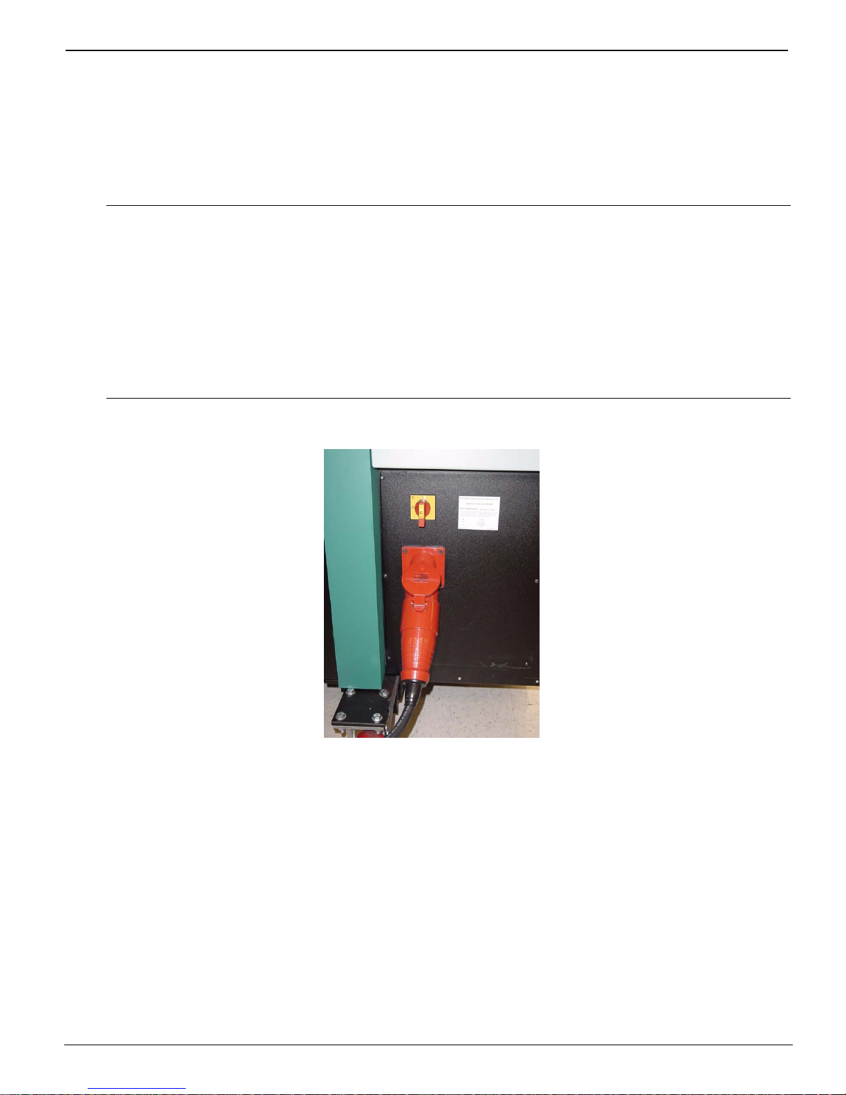
1.4Switching On or Off
The printer is to be powered On/Off only by a trained and qualified service technician (see
Figure 1-2). Position the power cord so that it does not pose a hazard when someone walks
around or accesses the doors on the printer
Important: Full-time AC power is required to maintain negative pressure on the inkjet
heads. Without this pressure, ink will drain out of the heads until the ink
reservoirs are empty. If not rectified, permanent damage to the heads could
occur.
The printer may contain a battery back-up vacuum control option to
maintain negative pressure for approximately 48 to 72 hours. This vacuum
backup is intended for emergency use only during power outage.
1.5Precautionary Measures
The battery back-up vacuum control option prevents ink from draining out of the reservoirs
for 48 to 72 hours if an AC power outage occurs. This back-up option is intended for
emergency use only. If the printer will be without power for a longer period of time, all ink
must be flushed from the system. Contact your Customer Service representative to perform
this function.
The battery back-up unit power switch should always be in the ON (up) position to protect
the system and charge the battery. The battery should maintain the printer vacuum for 48
to 72 hours. It is normal for the vacuum pump to run continuously when the printer has
12/9/04 1-5
Figure 1-2 Circuit Breaker Switch Location

Océ | Product Overview
lost power and running on battery back-up. If the power switch is left in the OFF (down)
position, the printer will not be protected and the battery will eventually discharge (see
Figure 1-3).
Power Switch
B
Figure 1-3 Battery Back-up Option
To verify the battery back-up unit is functional, perform the following steps:
1. Power down the printer.
The battery back-up unit should power up the vacuum pump immediately upon
losing power. If the vacuum pump does not start running, check the position of the
battery back-up power switch. If the vacuum pump fails to run with the switch in
either position, the battery may be discharged and require charging.
2. Power the printer back up.
The battery back-up unit should power down the vacuum pump immediately upon
the return of system power.
If the printer does not have the battery back-up vacuum control option and must be
powered off for more than two hours, you must call your Customer Service representative
to flush all ink from the system.
Though powered on, if the printer will not be printing for a period longer than two weeks,
contact your Customer Service representative to flush all ink from the system.
1-6

Arizona 600 Technical Specifications
1.6Arizona 600 Technical Specifications
Writing Technology.......................Piezoelectric inkjet with 504 nozzles per
color, six colors (C, M, Y, K, LM, LC)
Resolution.....................................Up to 617 x 617 dpi
2
Print Mode/Speed.........................• Up to 46.5 metres
(500 square feet) per
hour in 2-pass mode
2
• Up to 23.2 metres
(250 square feet) per
hour in 4-pass mode
2
• Up to 18.6 metres
(200 square feet) per
hour in 8-pass mode
Inks ..............................................• 5500-series and 6600-series inks in Cyan,
Magenta, Yellow, Black, Light Magenta, and
Light Cyan solvent-based pigmented inks,
packaged in 3.78-liter (1-gallon) bottles
• 440-series inks packaged in 3-liter bottles
Color Handling..............................ColorBlend Technology for overall
smoothness and increased detail in light to
midtone colors
Image Processing.........................Accepts proprietary bit-level image data,
Onyx PosterShop
®
Server Color Production
Software (RIP) available as an option
Media Type...................................Variety of uncoated vinyl films and inkjet
paper-based media
Media Handling.............................Roll-fed, reel-to-reel direct imaging process,
or reel-to-sheet with the Print & Go feature
Media Specifications
Width.....................................• Minimum: 91.4 cm (36 inches)
• Maximum: 190.5 cm (75 inches)
Thickness..............................• Minimum: 5 mils (.13 mm/.005 inches)
• Maximum: 30 mils (.76 mm/.030 inches)
Supply roll diameter..............• Maximum: 17.8 cm (7.00 inches)
Image Width..................................• Media width minus 2.97 cm (1.17 inches)
when printing single spit stripe
• Media width minus 4.93 cm (1.94 inches)
when printing dual spit stripes
On Board Hard Drive....................One 74-Gigabyte hard drive
Connectivity..................................LVD-SCSI-3 for long-length communications
12/9/04 1-7
(maximum 12 meters/40 feet)

Océ | Product Overview
Power Requirements
North America.......................200-240 VAC, 3-phase, 40 amps per phase,
60 Hz
Europe ..................................380-415 VAC, 3-phase, 40 amps per phase,
50 Hz
Print & Go Power Requirements..100-240 VAC, 0.4 amps, 50/60 Hz
Environment .................................Optimum Storage
Operating Range
Temperature
Temperature..........................18.3°C to 26.7°C 15.6°C to 32.2°C
(65°F to 80°F) (60°F to 90°F)
Humidity................................40% to 60% RH 10% to 80% RH
noncondensing noncondensing
Altitude..........................................Up to 2,438 meters/8,000 feet
Printer Dimensions.......................350.52 cm W x 111.76 cm D x 147.78 cm
(H138 in. W x 44 in. D x 57 in. H) with casters
Printer Weight...............................1093.2 kg/2410 lbs
1-8
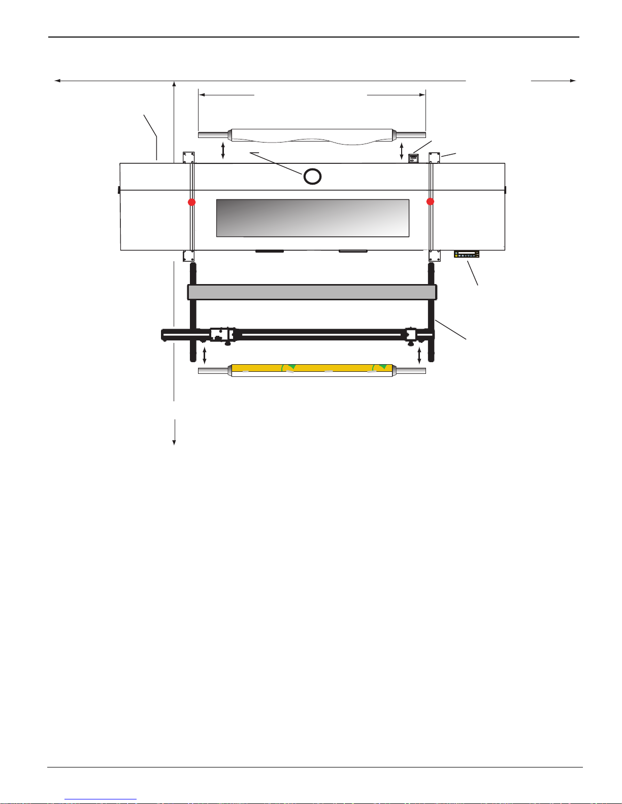
1.7Components Reference
t)
A
Panel Mount AC
Connector Location
Min. 4 ' (1.2 m)
87.50" (222.25 cm) 2x
Supply Mandrel & Media
6" (15.24 cm) Dia. Exhaust Duct
Components Reference
20' (6.1 m)
SCSI
Port Plate
Removable Caster 4x
ccess Doors
Machine
Stop
T op View
Recommended Ceiling
Height = 8'6" (2.59 m)
13' (3.96 m)
Take-up Mandrel & Media
Figure 1-4 Clearance Requirements (Footprint)
Machine
Stop
Control Panel
External Media
Takeup Unit
Access Doors
Clearance Requirements (Footprin
Note: drawing not to scale 10-08-03
1.8Safety Information
MSDS
Read and practice safety guidelines as outlined in the Material Safety Data Sheet (MSDS)
for each ink. Post the document in the work area as required by prevailing law.
Personal Safety
The operator should wear butyl rubber gloves, a protective apron, an NIOSH-approved
respirator (half-mask organic vapor respirator), and safety glasses with side shields when
handling inks.
12/9/04 1-9

Océ | Product Overview
Risks Associated with Handling Inks
The Arizona 600 printer uses solvent-based inks; the liquid and the fumes are combustible.
The inks may cause eye irritation or skin irritation upon prolonged or repeated contact. The
inks may be absorbed through the skin and may cause respiratory system irritation and
nervous system impairment.
What to do with Ink Spills on Surfaces
Observe precautions as noted above, then:
1. Ventilate the area
2. Contain the spill
3. Cover with absorbent material
4. Collect spilled absorbent material
5. Place in a closed container
6. Clean up residue with water (do not release to waterways or sewer)
7. Incinerate in a permitted hazardous waste incinerator
What to do with Ink Spills on Persons
• Eye contact: Immediately flush eyes with large amounts of water. Get
immediate medical attention.
• Skin contact: Flush skin with large amounts of water and wash with soap. If
irritation persists, get medical attention.
• Inhalation: Remove person to fresh air. If not breathing, get immediate
medical attention and give artificial respiration. If breathing is difficult, get
immediate medical attention.
• If swallowed: Call a physician immediately. Only induce vomiting at the
instructions of a physician. Never give anything by mouth to an unconscious
person.
1-10
2 Ink System
2.1Handling Inks
The Arizona 600 printer uses solvent-based pigmented inks in cyan (C), magenta (M),
yellow (Y), black (K), light magenta (LM) and light cyan (LC) in 1-gallon (3.78-liter)
replaceable supply bottles for 5500-series and 6600-series inks. The 440-series inks are in
3-liter bottles. Bottles should be visually checked daily. Read and practice the safety
guidelines as outlined in the Material Safety Data Sheet (MSDS) for each ink, and post
the document in the work area as required by prevailing law.
For personal safety, the operator must wear the following safety gear when handling inks:
•Rubber gloves
• Protective apron
• NIOSH-approved respirator (half-mask organic vapor respirator)
• Safety glasses with side shields
The liquid ink and its fumes are combustible. They may also cause eye and skin irritation
upon prolonged or repeated contact. Ink may be absorbed through the skin and the fumes
cause respiratory system irritation and nervous system impairment.
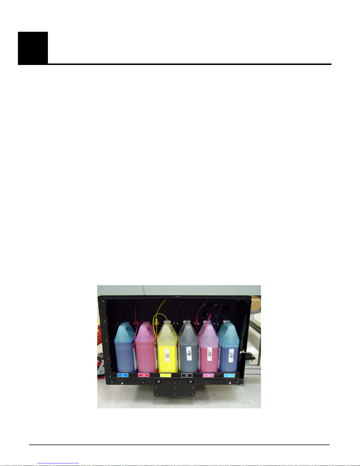
2.1.1Ink Supply Tray
The ink supply tray is located at the lower left end of the printer (see Figure 2-1). Observe
all bottle locations and warning labels on and around the ink supply tray.
Figure 2-1 Ink Tray (1-Gallon Bottles Shown)
12/9/04 2-1
Océ | Ink System
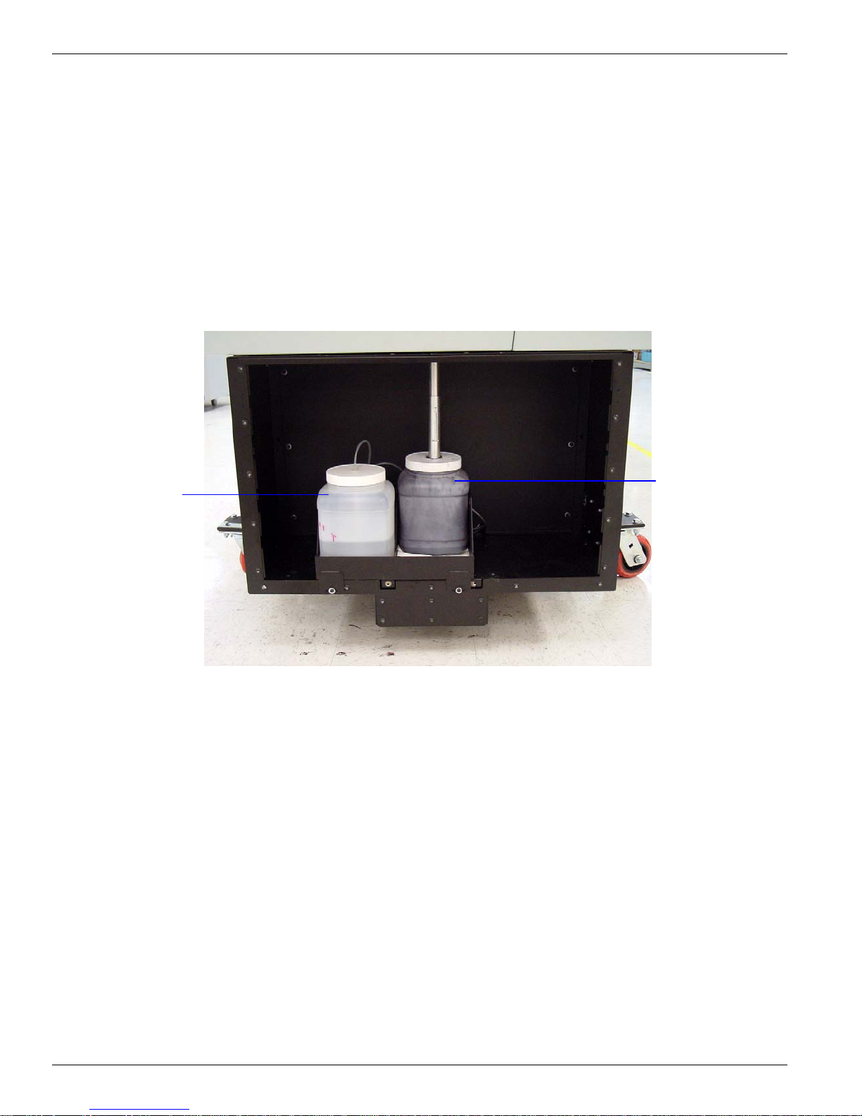
2.1.2Cleaning Fluid or Capping Fluid and Waste Bottles
The cleaning fluid (for 5500/6600-series inks) or capping fluid (for 440-series inks) is used
to supply and preserve the capping station foam pads during operation of the printer (see
Figure 2-2). The cleaning fluid (for 5500/6600-series inks) or capping fluid (for 440-series
inks) tray has a level sensing device to detect when the bottle is empty. When notification
is received from the printer, the operator must refill the cleaning fluid (for 5500/6600-series
inks) or capping fluid (for 440-series inks) bottle.
The waste bottle collects the purged ink from the capping station. The waste bottle tray has
a level sensing device to detect when the bottle is full. If the waste bottle appears full or the
printer control panel is signaling that the bottle requires emptying, then do so in accordance
with state and local laws or in accordance with the MSDS sheets (see Figure 2-2).
Cleaning Fluid or
Capping Fluid
Figure 2-2 Cleaning Fluid or Capping Fluid Container and Waste Container
2.2Ink Supply Changes
Waste Bottle
To reduce the chance of poor image quality, do not shake the ink supply bottles before
installation or during printing. Shaking does not improve ink consistency but may
introduce unwanted air bubbles into the ink system. Follow these steps to correctly replace
the ink supply bottles:
Follow the control panel message and/or go to the Ink Menu to select the color ink to install
or replace.
2-2
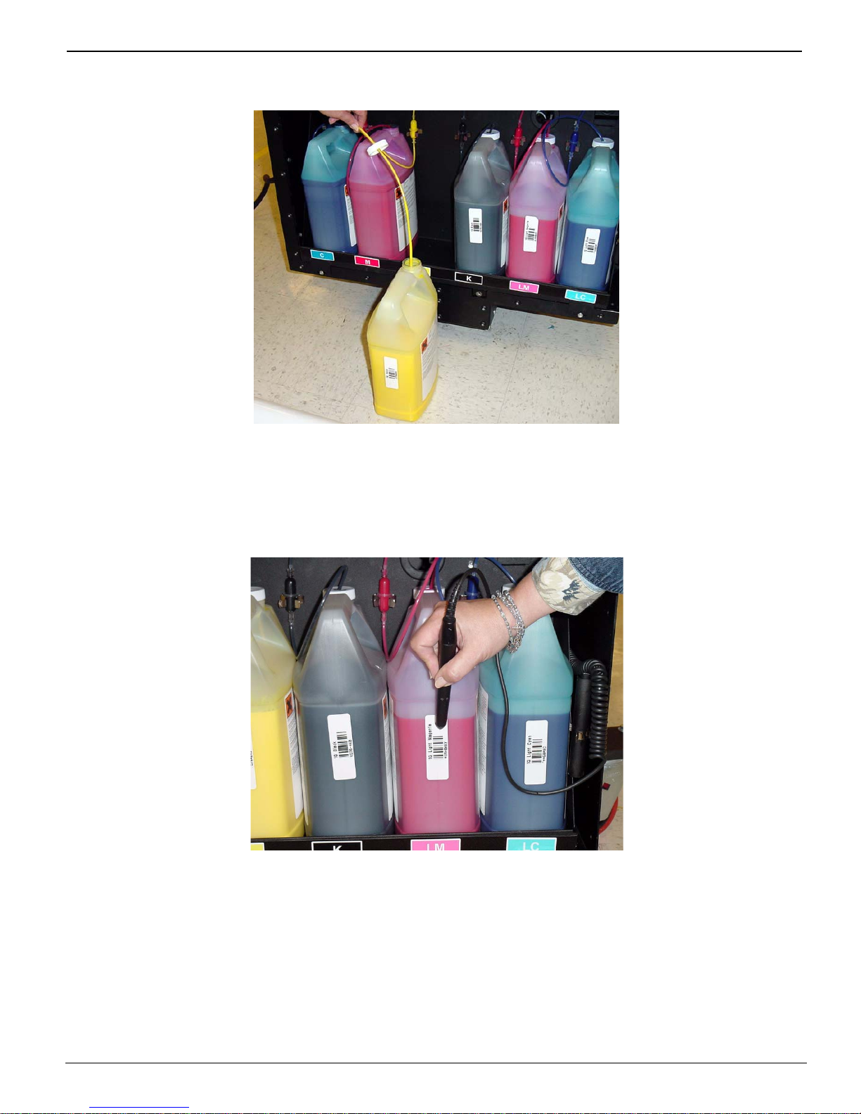
Ink Supply Changes
1. Locate the container on the ink supply tray that requires replacement and remove the
cap and ink pick-up tube from the bottle (see Figure 2-3). Remove the empty bottle.
Figure 2-3 Supply Ink
2. The barcode on each bottle must be scanned each time a new bottle of ink is added
to the printer (see Figure 2-4). For additional information about scanning the
barcode and ink bottle installation (see "Ink Bottle Installation" on page 4-28).
Figure 2-4 Scanning the Ink Barcode
3. Remove the ink bottle cap and protective cover on the new ink supply bottle. Place
it on the ink supply tray and insert the ink pick-up tube and cap. It should be placed
loosely back on top of the bottle but not screwed down. If the cap seals too tightly,
the printer may not pump the ink to the reservoirs.
12/9/04 2-3
Océ | Ink System
2.3Ink Filter Changes
The ink filter (OIN #3012001622) can easily be changed without mess by using the
following procedure.
Note: The ink filter must be changed after four bottles of ink have been filtered.
The use of personal protection consistent with the safety recommendations noted at the
beginning of this chapter is strongly recommended.
1. Remove the ink bottle from the printer and sit on the floor near the end of the
printer.
Gently pull the filter away from the bulkhead and out of the printer.
Note: Observe the ink flow direction arrow on the filters for proper orientation.
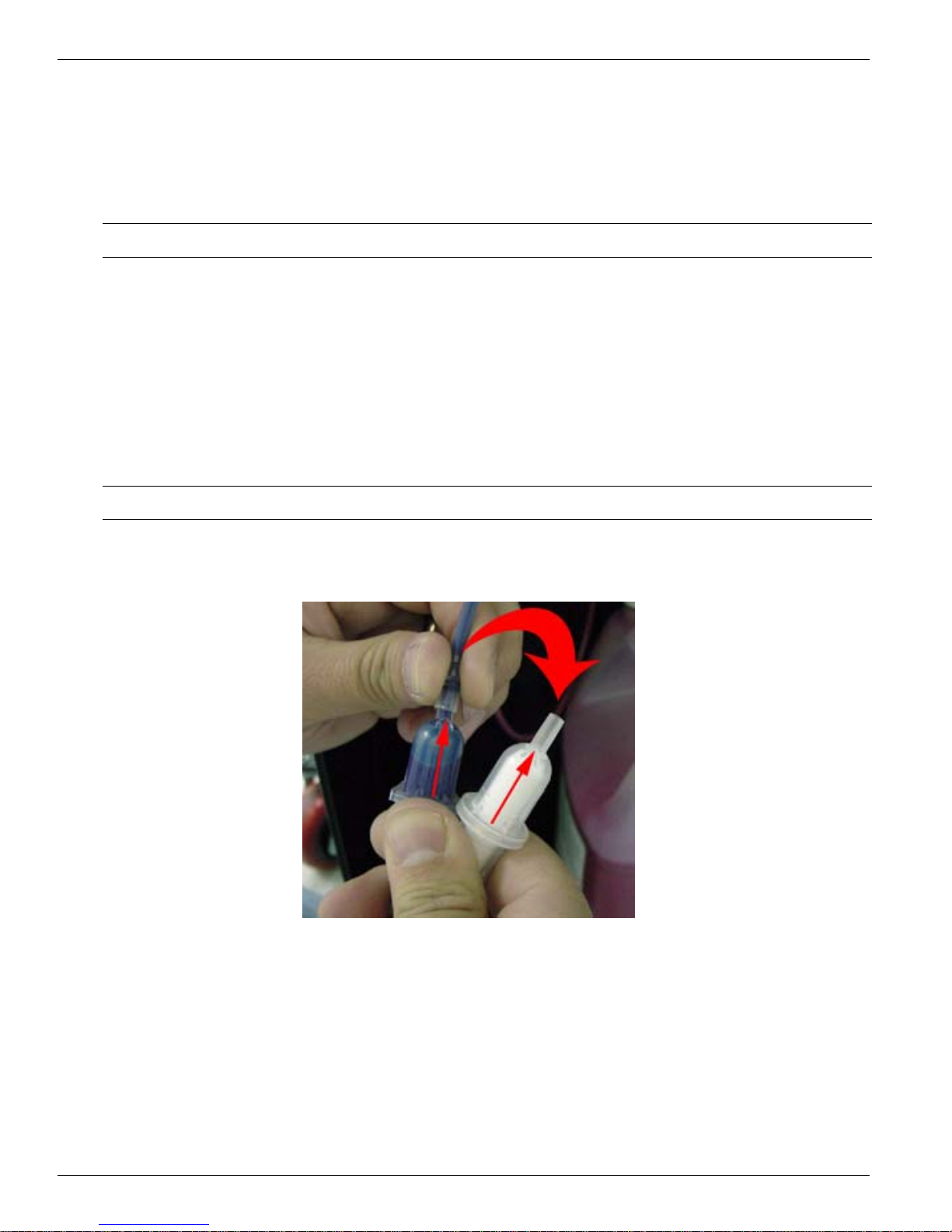
2. With the new filter in hand next to old filter, remove the tube from the top of the
old filter and place on the top of the new filter (see Figure 2-5 and Figure 2-6).
Figure 2-5 Remove the Top Tube from the Old Filter
2-4
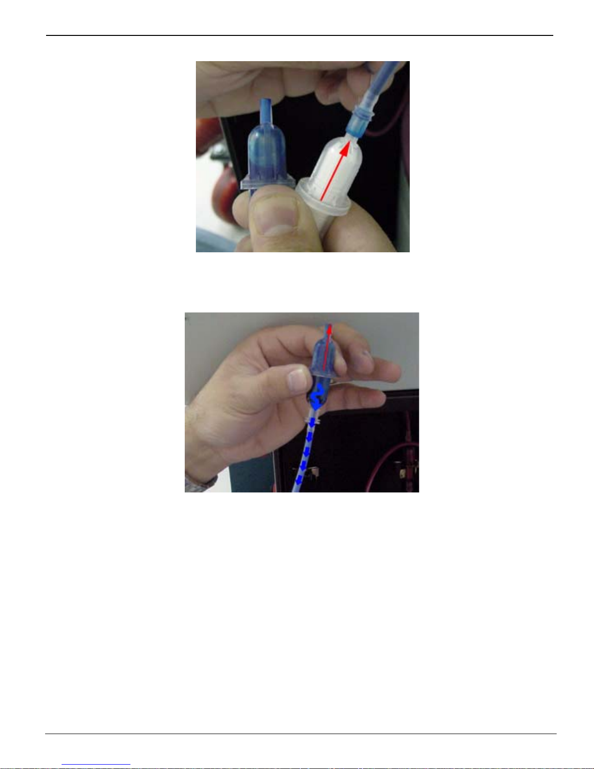
Ink Filter Changes
Figure 2-6 Attach Tube to the New Filter
3. Hold the old filter up until the ink drains back into the supply bottle (see Figure 2-7).
Figure 2-7 Allow th e In k to Drain from the Filter into the Supply Bottle
12/9/04 2-5
Océ | Ink System
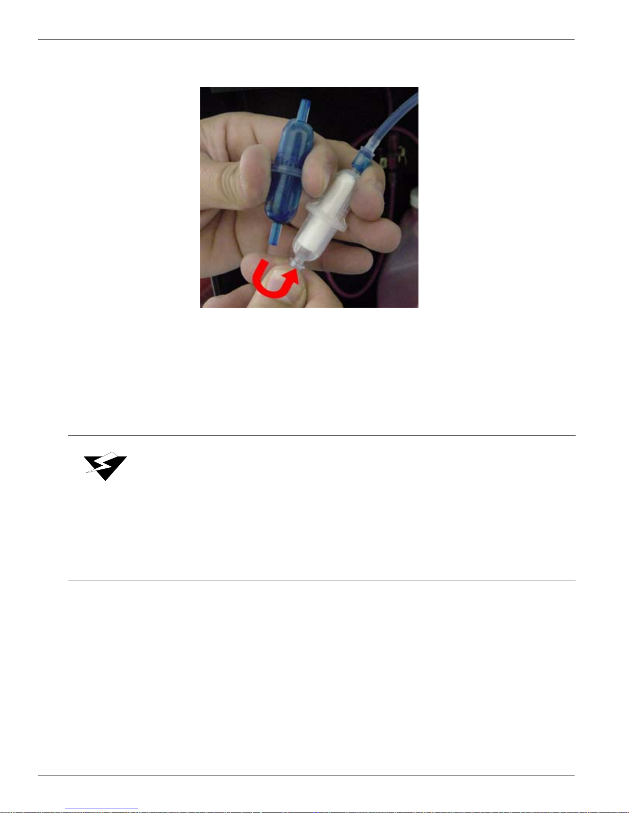
4. When the ink has drained from the old filter, disconnect the fitting from the bottom
of the old filter and connect it to the new filter (see Figure 2-8).
Figure 2-8 Moving the Supply Tube from the Bottom of the Old
Filter to the New Filter
5. Reattach the filter to the rear bulkhead and return the supply ink bottle to the supply
bottle tray.
Warning:
Océ Display Graphics Systems accepts no liability when ink other than
Océ Display Graphics Systems recommended ink is used. Customers
voluntarily using ink not supplied by Océ Display Graphics Systems
assume all risk of damage that might result. Customer agrees to waive
any claims or rights they may otherwise have against Océ Display
Graphics Systems or its agents for damage and/or loss of business
resulting from use of ink other than Océ Display Graphics Systems ink.
2-6

3 Media System
3.1Media Specifications
For detailed media specifications, refer to "Arizona 600 Technical Specifications" on
page 1-7.
3.2Media Handling
The Arizona 600 printer loads and prints centered on the media. Do not attempt to left
or right justify the media during installation. Take-up cores should always be the same
width as the supply media, and the attached media should be centered on the take-up
core. The supply media is mounted from the rear of the printer, while the take-up is
located at the front just behind the IR heater door. Dancer rollers are positioned between
the vacuum platen and both the supply and take-up media mandrels to aid in correctly
tensioning the media during printing.
To ensure the highest quality printing, protect the media coating and store it at the
recommended temperature and humidity. Media should be stored in a horizontal
position and conditioned to the printer environment. Place media in the same room as
the printer for 2 to 24 hours before use.
12/9/04 3-1
Océ | Media System
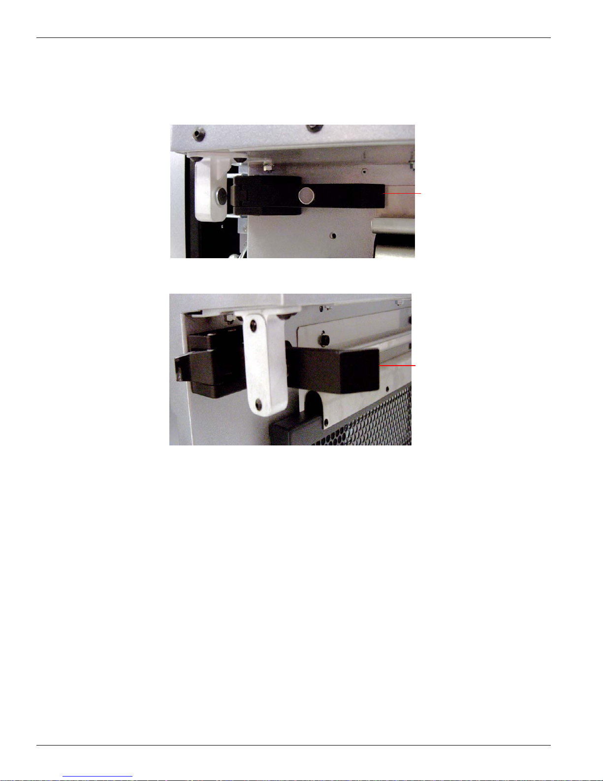
3.2.1Opening the Door
The first step in loading media is to open the IR-heater door on the front of the printer.
Begin by releasing the black clips on both sides of the door (see Figure 3-1) and
(see Figure 3-2).
Handle
Figure 3-1 Left Clip Closed
Handle
Figure 3-2 Left Clip Open
Grasp the door using the two handles and pull the door towards you and down.
3.2.2Closing the Door
To close the door, grasp the door using the two front handles and pull the door up and away
from you. Secure the black clips on each side of the door.
3.2.3Media Support System
Océ Display Graphics Systems strongly recommends that two people change supply and
take-up media rolls. The customer’s media support system should be able to support the
weight of a full media roll. Position the media support system as close as possible to the
3-2
 Loading...