

Page 1
Recycled paper is used for the inside pages of this book.
Océ 750
User's Manual
Page 2

MAINTENANCE AGREEMENT
Océ 750 Printer will give you many years of trouble-free service. To ensure high-quality printing performance
and to prevent premature wear or failure of precision parts and components, schedule periodic cleaning and
routine adjustments.
We recommend that you contact your service center to discuss the benefits and advantages of Océ's Customer
Service Maintenance Agreement and to be shown how a maintenance plan can be tailored to your individual
printing needs.
NOTICE:
Océ-USA, Inc. and OcéPrinting Systems, Inc. have made every effort to ensure that the information in this
manual is complete and accurate. However, constant efforts are also being made to improve and update the
product. Therefore, Océ shall not be liable for errors in this manual or for any consequential damages resulting
from the use of this manual. The information contained herein is subject to change without notice.
FEDERAL OR STATE STATUTES MAY PROHIBIT THE COPYING OF CERTAIN DOCUMENTS OR
INFORMATION, RESULTING IN FINES OR IMPRISONMENT FOR VIOLATORS.
MANUAL PART NUMBER:
OP-Oce750-03
WEB SITE ADDRESS
http://www.oceusa.com
CORRESPONDENCE:
Correspondence regarding this manual may be mailed to the address shown below.
Océ-USA, Inc.
5450 N. Cumberland Avenue
Chicago, IL 60657
Océ Printing Systems USA, Inc.
5600 Broken Sound Blvd.
Boca Raton, FL 33487
Page 3

Section 1: Introduction
To the User.......1-2
Features Overview.......1-3
Introduction 1-1
Page 4

Introduction
To the User
Welcome to the Océ 750 Printer, which includes the main body engine, the print
controller, and the optional network interface card. Separate user documentation is
provided with the print controller and the network interface card.
This User's Manual describes the layout of the main body machine configured with both
standard and optional equipment and explains control panel functions and procedures
for all operations. This manual also includes basic engine specifications, information on
media requirements, maintenance, supplies, safety measures and troubleshooting tips.
Be sure to read this manual thoroughly before operating the equipment and keep it in a
handy location for the convenience of all users.
Océ is committed to serving you in the best way possible and we welcome your
comments on this manual. If you wish to send us your comments, please use our mailing
address displayed at the front of the book.
1-2 Introduction
Page 5

Introduction
Features Overview
Connects to the Network or Main Frame via the Network Print Controller75 and the
Network Interface Card, enabling the system to function as a network printer or print
server on the network.
The Océ 750 electronically digitizes images then outputs in various ways controlled by
software. The digitized image is represented as pixels on a screen or as dots per inch
(dpi) on hard print.
• 600dpi Mode
Scans with a higher resolution (600dpi) than normal mode (400dpi).
• All-Image Area
Prints completely to the edges of the paper to avoid image loss.
• ATS - Automatic Tray Switching
Automatically switches to another tray when a tray becomes empty during a print job.
• Auto Low Power
Automatically lowers the power after a specified period of printer inactivity.
• Auto Reset
Automatically resets to auto mode defaults after a specified period of printer inactivity.
• Auto Shut-Off
Automatically shuts off the main body power after a specified period of printer inactivity.
• Chapter
Places chapter pages on the righthand side in duplex mode.
• Duplex Mode
Selects the duplex printing mode.
• Manual Shut-off
Shuts off the main power with the [
• Non STD Size for Multi-Sheet Bypass Tray
Allows you to indicate a special paper size to be loaded in the Multi-sheet bypass tray.
POWER SAVER ON/OFF] key.
Introduction 1-3
Page 6

Introduction
Features Overview (continued)
• Output modes with Finisher or Finisher-Folder Installed:
Non-Sort, Sort, Staple-Sort, and Group modes using the primary (main) tray
Non-Sort Face Down exit, Non-Sort Face Up exit, Group Face Down exit, and
Group Face Up exit modes using the secondary (sub) tray
Stapling & Folding, and Folding modes using the booklet tray (Finisher-Folder
only)
• Output modes with Finisher / Finisher-Binder and Cover Sheet Feeder Installed:
Cover Sheet mode
Manual Staple mode
For details of each output mode, see Section 6: Output Modes.
• Power Saver
Automatically reverts to nominal optimal efficiency power after a specified period of
printer inactivity. Normal power resumes after a brief warm up period by pressing the
[POWER SAVER ON/OFF] key on the Control panel.
• Punching Mode for Finisher / Finisher-Folder with
Punching Unit Installed: Punch three holes in output prints.
• Repeat Image
Repeats the selected horizontal image area down the page as many times as permitted
by the repeat width setting (10 ~ 150mm) permits in manual or auto mode.
• Reserve
Scans subsequent print jobs while the Océ 750 is busy printing or printing.
• Resolution (400dpi, 600dpi)
400dpi and 600dpi resolution modes provide optimal image quality for photos,
complicated graphics and text requiring high to very high compression.
• Reverse Image
Reverses the image from black-on-white to white-on-black or vice versa.
• Stamp/Overlay
Imprints a stamp, watermark, or scanned image onto the print image.
• Staple
Selects the stapling position and number of staples (3 positions).
1-4 Introduction
Page 7

Introduction
Introduction 1-5
Page 8

Page 9

Section 2: Safety Information
User Instruction.......2-2
Machine Safety Labels.......2-2
Label Locations.........2-3
Regulations.......2-5
FCC Regulations.........2-5
Canadian Department of Communications Regulations.........2-5
FDA Regulations.........2-5
Installation and Power Requirements.......2-6
Machine Handling and Care.......2-8
Routine Safety.......2-9
Finisher Capacity Requirements..... 2-10
Safety Information 2-1
Page 10

Safety Information
User Instructions
The following pages include important safety information, which you must read and
understand before you attempt to operate the printer. If you have any concerns about
safety matters, please contact your service representative. Keep this manual
permanently located with the printer, so that this safety information is readily available.
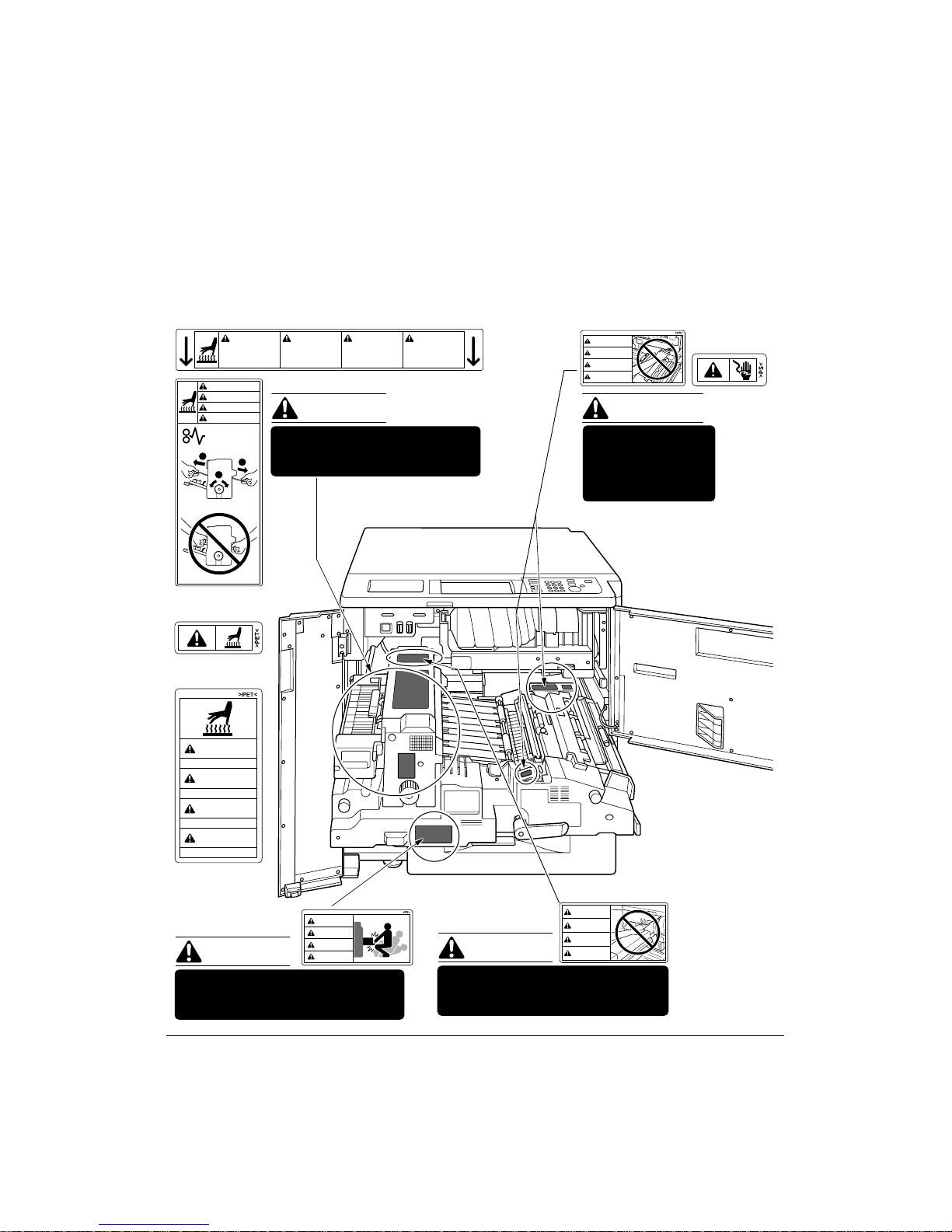
Machine Safety Labels
Machine safety labels are attached to the internal area of the printer. The purpose of
safety labels is to alert you of imminent or potentially hazardous situations or conditions.
Be sure to heed all safety label information. If any safety label becomes illegible due to
soilage, etc., please contact your service representative for information about label
replacements. Sample safety labels are shown on the following page.
TO AVOID GETTING BURNED Do not touch any machine area that you are advised not
to touch by a warning or caution label.
DO NOT REMOVE WARNING OR CAUTION LABELS
Clean labels as needed to maintain legibility. If any warning or caution label is removed
or becomes illegible from soilage, please contact your service representative for
information about label replacements.
The following standard safety categories are commonly used on product labeling.
DANGER:
Danger indicates an imminent hazardous situation, which, if not avoided, will
result in death or serious injury.
Note: The DANGER category is not required for this product, and is included here for general user
information.
WARNING:
Warning indicates a potentially hazardous situation, which, if not avoided, could
result in death or serious injury.
CAUTION:
Caution indicates a potentially hazardous situation, which, if not avoided, may
result in minor or moderate bodily injury.
NOTICE: Notice provides information on the correct handling or use of the machine to prevent
breakage of the printer or some machine part, etc. It does not indicate concern for personal safety.
2-2 Safety Information
Page 11
Safety Information
Machine Safety Labels (continued)
Label Locations
CAUTION
This internal area is very
hot. To avoid getting
burned, DO NOT TOUCH.
CAUTION
ATTENTION
PRECAUCION
CUIDADO
ATTENTION
Cette zone interne est
très chaude. Pour éviter
de se brûler, NE PAS LA
TOUCHER.
(Both sides of the fixing unit)
CAUTION
PRECAUCION
Esta zona interior está
muy caliente. Para no
quemarse NO TOCAR.
The fixing unit is very hot.
2
1
To avoid getting burned DO NOT
2
TOUCH.
(Top surface of
the fixing unit)
(Inside of
the fixing unit)
CAUTION
High temperature!
ATTENTION
Température élevée!
PRECAUCION
¡Temperatura alta!
CUIDADO
Alta temperatura!
(Front side of
the fixing unit)
CAUTION
ATTENTION
CAUTION
PRECAUCION
CUIDADO
The conveyance fixing unit is heavy.
Use care and draw it out gently;
otherwise you may be injured.
CUIDADO
Alta temperatura. NÃO
TOQUE nesta área
interior, pois há risco de
queimadura.
CAUTION
DO NOT put your hand between the
main body and developing fixing
unit; otherwise you may be injured.
WARNING
DANGER
ADVERTENCIA
ADVERTÊNCIA
WARNING
This area generates
high voltage. If
touched, electrical
shock may occur. DO
NOT TOUCH!
CAUTION
ATTENTION
PRECAUCION
CUIDADO
Safety Information 2-3
Page 12
Safety Information
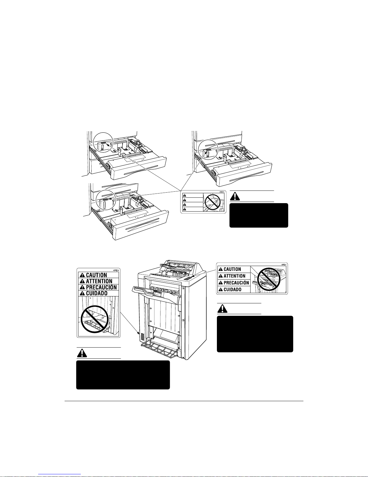
Machine Safety Labels (continued)
Label Locations (continued)
Tray 3
Tray 1
CAUTION
ATTENTION
PRECAUCION
CUIDADO
Tray 2
CAUTION
DO NOT put your hand
between the main body
and tray; otherwise you
may be injured.
(Finisher / Finisher-Binder)
CAUTION
(Finisher-Binder only)
CAUTION
Inside the lower paper exit outlet
is the roller drive unit.
DO NOT put your hand into it;
otherwise you may be injured.
2-4 Safety Information
Use care after opening the
paper exit outlet. DO NOT
put your hand into it;
otherwise you may be
injured.
Finisher-Binder
Page 13

Safety Information
Regulations
FCC Regulations
Warning: The Océ 750 generates, uses, and can radiate radio frequency energy. If it is
not installed and used in accordance with the instruction manual, interference with radio
communications may result. This equipment has been tested and found to comply with
the limits for a Class A computing device, pursuant to Subpart B, Part 15, of FCC rules,
which are designed to provide reasonable protection against interference from such
equipment when it is operating in a commercial environment.
Users operating this equipment in a residential area are likely to cause interference, in
which case they may be required to correct the interference at their own expense.
Canadian Department of Communications Regulations
Le présent appareil n’émet pas de bruits radioélectriques dépassant les limites
applicables aux de Classe A prescrites dans le règlement sur la brouillage
radioélectrique édicté par Le Ministère des Communications du Canada.
This equipment does not exceed the Class A limits for radio noise emissions as set out
in the radio interference regulations of the Canadian Department of Communications.
FDA Regulations
This Printer is certified as a “Class 1” laser product under the U.S.Department of Health
and Human Service (DHHS) Radiation Performance Standard according to the Radiation
Control for Health and Safety Act of 1968. Since radiation emitted inside this printer is
completely confined within protective housings and external covers, the laser beam
cannot escape during any phase of normal user operation.
Safety Information 2-5
Page 14
Safety Information
Installation and Power Requirements
CAUTION:
FAILURE TO HEED THE FOLLOWING CAUTIONS MAY RESULT IN BODILY INJURY AND/OR
MACHINE DAMAGE
❒ FIRE PREVENTION
Install machine away from flammable or volatile materials. Routinely check for abnormal
heat from power cord and/or plug.
❒ SHORT CIRCUIT FROM WATER DAMAGE
Do not install or operate this equipment outdoors near a lake, pond, or river, etc.; and do
not allow the machine to come in contact with splashes of rain, water, or any liquid.
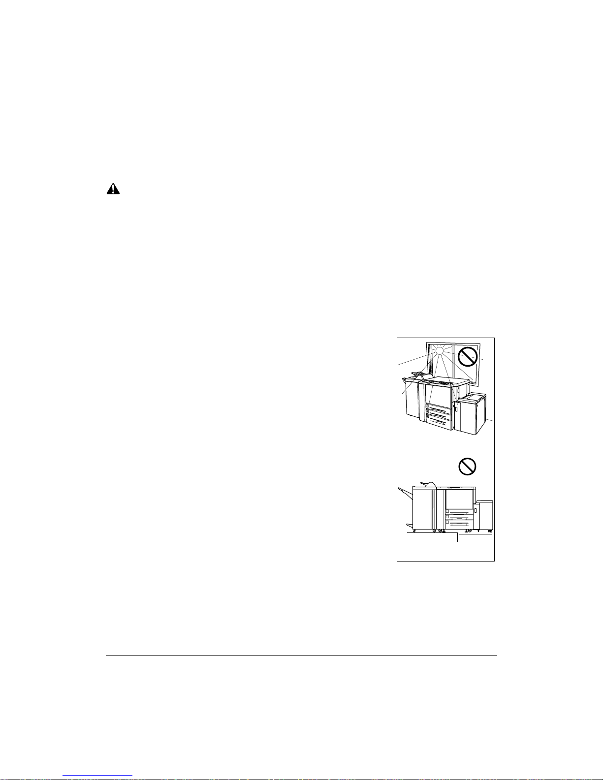
❒ TEMPERATURE AND HUMIDITY
Install the machine away from direct sunlight, heat sources
(stoves, heaters) and cold temperatures (air conditioners).
Avoid any environment that is outside 50°~86°F (10°~30°C),
with 10~80% humidity.
❒ VENTILATION
Do not allow the machine to come in contact with dust or
ammonia gas, or fumes from printing or cleaning solutions,
etc.; otherwise, image quality will be poor. Install the machine
in a well-ventilated area, for comfort; otherwise, an ozone odor
will be detected during large print runs. When in use, the
printer generates ozone in amounts too small to be hazardous
to the human body.
Temperature
❒ VIBRATIONS
If the machine is constantly vibrated or jolted, trouble may
occur. Install the machine on a level, horizontal floor, free from
vibrations.
❒ SPACE ALLOTMENT
Install machine in an area with adequate space for performing printer operations,
replacing supply items, and conducting preventive maintenance. See Site Requirements,
Section 3.
❒ MACHINE RELOCATION
Before moving the machine to another location, contact your service representative.
2-6 Safety Information
Vibration
Page 15

Safety Information
Installation and Power Requirements (continued)
CAUTION:
FAILURE TO HEED THE FOLLOWING CAUTIONS MAY RESULT IN MACHINE DAMAGE,
OVERHEATING, RISK OF ELECTRICAL SHOCK, AND/OR PERSONAL INJURY
❒ PLUG SOCKET
A plug socket is limited in capacity. Use an exclusive power source for this machine;
otherwise, overheating and/or smoking may occur. The total power consumption of the
main body, plus all peripherals, must not exceed the capacity of the main power supply.
Be sure the socket outlet is near the equipment and is easily accessible.
❒ PLUG AND CORD (LEAD)
Unless the power plug is firmly inserted into the socket, an accident from overheating
and/or smoking may occur. Firmly insert the power cord plug into the electrical outlet
before turning on the printer power switch. If the inserted plug is loose in the socket,
disconnect it, and consult an electrician for repair; but, do not attempt to operate the
machine. Be sure the socket outlet is near the equipment and is easily accessible.
A damaged power cord may result in overheating, short circuit or fire. Do not bend,
crush, wind, kick or strike the cord with any item. Do not roll up the cord. If the main body
power cord is bent or damaged, immediately contact your service representative; do not
attempt to repair it yourself, or continue to operate the machine.
❒ ADAPTERS AND PLURAL LOADS
Never use adapters and never connect plural loads or a branched socket to one socket
outlet; otherwise, overheating or fire may occur.
❒ EXTENSION CORDS (LEADS)
An extension cord or lead is limited in capacity. Unless the cord or lead has adequate
capacity, smoking and overheating may occur. Should smoking and/or overheating
occur, contact an electrician immediately. If you require further information about power
requirements, power consumption, extension cords, adapters and connectors, please
contact your service representative, and consult your electrician.
Safety Information 2-7
Page 16

Safety Information
Machine Handling and Care
WARNING:
FAILURE TO HEED THE FOLLOWING WARNING MAY RESULT IN DEATH OR SERIOUS INJURY AND/
OR MACHINE DAMAGE
❒ MACHINE CONTACT
Never touch internal high voltage area indicated with a WARNING label.
Never touch the drum surface.
Never put your hand into the developing unit when removing mishandled paper.
CAUTION:
FAILURE TO HEED THE FOLLOWING CAUTIONS MAY RESULT IN MACHINE DAMAGE,
OVERHEATING, AND/OR PERSONAL INJURY
❒ MACHINE CONTACT
Never touch internal high temperature or magnetism areas indicated with a CAUTION
label. Never insert your hand into the fixing unit when removing paper. Never touch the
inside of the main body for any purpose except moving mishandled paper or adding
toner. Use care when withdrawing the conveyance fixing unit.
❒ MACHINE CARE
Do not drop paper clips, staples or other small metallic objects into the printer, or spill
water or any other liquid into the machine.
Do not use the machine surface to support vases, books, etc. These items will interfere
with the work space and may cause damage to the machine or to original documents.
❒ ABNORMAL CONDITIONS
If any abnormal sound, odor, or smoke generates from the machine, immediately stop
using the printer, turn off the main power switch, disconnect the plug and contact your
service representative.
If a circuit breaker is tripped, or if a fuse blows, stop using the machine and contact an
electrician. If more detailed information is needed regarding the power source or power
consumption of this machine, contact your service representative.
❒ MACHINE MODIFICATION
Do not modify the machine in any way or remove any part or screw. Never attempt to
perform any maintenance function that is not specifically described in this manual. Do
not connect the machine with any options other than those specified.
2-8 Safety Information
Page 17

Safety Information
Routine Safety
CAUTION:
FAILURE TO HEED THE FOLLOWING CAUTIONS MAY RESULT IN MACHINE DAMAGE,
OVERHEATING, AND/OR PERSONAL INJURY
❒ PERIODIC CHECK
Check for loose connection or excessive heat on power plug, damage to power cord
and/or plug (creased, frayed, scratched or cut, etc.). Be sure the plug is inserted fully,
and ground wire is connected correctly. If any abnormality occurs, do not continue to
operate the machine.
❒ SERVICE MESSAGES
If a service message displays, turn the machine off, disconnect the power cord from the
outlet, and report the condition to your service representative.
❒ TONER
Check to be sure toner in storage is out of the reach of children, or anyone who may be
incapable of handling it in a safe manner. Although toner is nontoxic, do not inhale or
swallow toner or allow it to come in contact with eyes. If toner is inhaled, consult a
physician immediately. If swallowed, drink plenty of water and consult a physician
immediately. If eye contact occurs, flush eyes with plenty of water and consult a
physician immediately. Please read the material safety data sheet provided with this
product for additional toner information.
❒ PAPER
Check paper to be sure it is according to the specifications outlined in Section 4.
❒ CLEANING MATERIALS
Check the type of cleaning material used on your machine to be sure it is recommended
by Océ. If necessary, check with your service representative. Never use cleaning
materials for purposes other than cleaning, and be sure to keep all cleaning materials
out of the reach of children or anyone who is incapable of using them safely.
❒ POWER SAVER
Use Power Saver mode for short periods of machine inactivity. When not using the
machine for long periods of time, turn power off, unless the weekly timer function is
operating.
❒ DISPOSAL OF THE PRINTER
Dispose of this printer according to your local regulations.
Safety Information 2-9
Page 18

Safety Information
Finisher Capacity Requirements
CAUTION:
FAILURE TO HEED THE FOLLOWING CAUTIONS MAY RESULT IN BODILY INJURY AND/OR
MACHINE DAMAGE
❒ FINISHER PAPER CAPACITY
To prevent paper misfeed, do not exceed the paper capacity of the Finisher.
Finisher /Finisher-Binder paper weight: 16 lb ~ 24 lb
When the selected print quantity exceeds the maximum paper capacity, remove sheets
as they are output from the finisher.
Paper capacities below are stated for 20 lb Bond. This Finisher also accepts the wide
orientation of regular sizes stated below.
Finisher: Finisher / Finisher-Folder
Primary (Main) tray: Non-sort/Sort/Group mode
500 sheets (5.5"x8.5"R)
3,000 sheets (8.5"x11", 8.5"x11"R)
1,500 sheets (11"x17", 8.5"x14")
The Secondary (sub) tray can be unloaded while the Océ 750 is running.
Set production is not limited by the capacity of the Secondary (sub) tray.
Primary (Main) tray: Staple-Sort mode
1,000 sheets* (11"x17" ~ 8.5"x11"/R)
* The maximum capacity varies according to the number of sheets to be
stapled.
Secondary (Sub) tray: Non-sort mode
200 sheets max.
Booklet tray (Finisher-Folder only)
100 sheets max. (11"x17", 8.5"x14", 8.5"x11", A4R)
(The maximum number of sheets varies, depending on the number of pages in
the booklet and whether Folding or Stapling & Folding is selected.)
Trimmer unit tray (Finisher-Folder with Trimmer unit only)
512 sheets max. (11"x17", 8.5"x14", 8.5"x11", A4R)
(The maximum number of sheets varies, depending on the number of pages in
the booklet and whether Folding or Stapling & Folding is selected. See p. 4-7.)
2-10 Safety Information
Page 19

Safety Information
Finisher Capacity Requirements (continued)
CAUTION:
FAILURE TO HEED THE FOLLOWING CAUTIONS MAY RESULT IN BODILY INJURY AND/OR
MACHINE DAMAGE
❒ FINISHER-FOLDER MODE OUTLET
Inside the Booklet mode outlet is the roller drive unit. DO NOT put your hand into it when
removing the folded or stapled & folded sheet; otherwise you may be injured.
❒ FINISHER / FINISHER-FOLDER PAPER EXIT OUTLET
To avoid injury when stapling large size prints, DO NOT put your hand into the open
Paper exit outlet.
Safety Information 2-11
Page 20

Page 21

Section 3: Machine Information
Océ 750 Overview.......3-2
Key Operator Functions.........3-3
Service, Repairs and Supplies.........3-3
Machine Labels.........3-3
Service Settings.........3-4
External Machine.......3-5
Internal Machine.......3-7
Standard Equipment.......3-8
Optional Equipment.......3-8
Finisher/Large Capacity Tray.......3-10
Trimmer Unit.......3-11
Punching Unit.......3-12
Site Requirements..... 3-13
Specifications..... 3-14
Machine Information 3-1
Page 22

Machine Information
Océ 750 Overview
The Océ 750 Printer provides high quality printing suitable for any IBM compatible PC
environment. The printer's main body engine works in conjunction with the New Open
Architecture (NOA) of the print controller to provide a flexible and modular way of
customizing the language interpreter, the I/O and communication, and the system
control. NOA supports a modular-based, object-oriented system software that enables
you to use the special software modules developed to enhance printing capabilities and/
or adjust the IP system to meet your special requirements.
The built-in electronic recirculating document handler (ERDH) provides dual access
capability, enabling the printer to receive a job while another job is printing or rasterizing.
This timesaving system allows you to work with optimal efficiency while the printer is
operating at peak capacity.
The advanced finishing system of the Océ 750 provides you with the option of sending
print jobs to the output tray face down and in correct order.
The Océ 750 printer is perfect for any work environment.
• use it as a non-network printer by connecting it to your PC with standard serial
or parallel port cabling.
• install the optional network interface card and use it as a standard network
printer supporting NetWare, AppleTalk (EtherTalk) or TCP/IP.
• install the Océ 750 as a high-end network printer in an AS 400/IBM Host
Environment.
Highlights of the Océ 750 include:
• 75 ppm
• 400/600 dpi
• duplex mode
• 3 standard paper trays plus a Multi-sheet bypass tray
• LCT, Finisher and Trimmer Unit and Punching Unit
3-2 Machine Information
Page 23

Machine Information
Océ 750 Overview (continued)
Key Operator Functions
Access to the Key Operator mode may require entry of a Key Operator password
previously set by your service representative. A Key Operator may make various custom
settings that affect printer functions. We recommend using a password to limit access to
the Key Operator mode to an authorized person.
Service, Repairs & Supplies
Service and repairs should be performed only by an authorized service representative.
To maintain personal safety and to avoid machine damage, never disassemble the
machine for any reason. To ensure optimal printing quality, use only supplies that
are recommended by Océ USA, Inc. and Océ Printing Systems USA, Inc. Use the
convenient form located at the end of the section to record all service, repair, and
supply orders.
Machine Labels
Machine labels are affixed to provide quick and easy instructions on loading paper,
adding toner, and clearing mishandled paper. Machine safety labels, affixed to key areas
of the internal machine, provide cautionary information to prevent personal injury or
damage to the equipment. Sample machine safety labels are shown in the
Information
section.
Safety
Machine Information 3-3
Page 24

Machine Information
Océ 750 Overview (continued)
Service Settings
Setting changes for the following functions can be made by your service representative.
Finisher-Paper Capacity
In the default condition, the Océ 750 will produce unlimited sets. If required, your service
representative can set the printer to stop printing when the number of prints exceeds
specified capacity.
Key Operator Password
Your service representative can set a 4-digit Key operator password to access the Key
Operator Mode Screen.
After this setting is made, a Password Entry Screen will be displayed when Key Operator
mode is selected from the Help Screen. The user or Key Operator will be required to
enter the valid Key Operator password before accessing the Key Operator Mode
Screen. It is recommended that the Key Operator password be noted and kept in a
secure place in the event it is forgotten. Otherwise, you will be required to contact your
service representative to obtain a password.
Weekly Timer
Your service representative can set a 4-digit Weekly timer master key code to enable
the Key Operator to gain access to the Weekly Timer Setting Menu Screen.
After this setting is made, the Weekly Timer Master Key Code Screen will be displayed
and will always require entry of the set Weekly Timer master key code to access the
Weekly Timer Setting Menu Screen.
Your service representative can set the Weekly Timer system to display the Weekly
Timer key on the Help Screen which enables you to view Weekly Timer settings.
Staple Sheet Capacity
Staple capacity is changeable, and may be set to 45, 40, or 35 by your service
representative.
Notice Message for ADD TONER/ PM CALL
Your service representative can set the printer message area to display “ADD TONER”
when the toner supply is low, or “PM CALL” when preventive maintenance is required.
3-4 Machine Information
Page 25
Machine Information
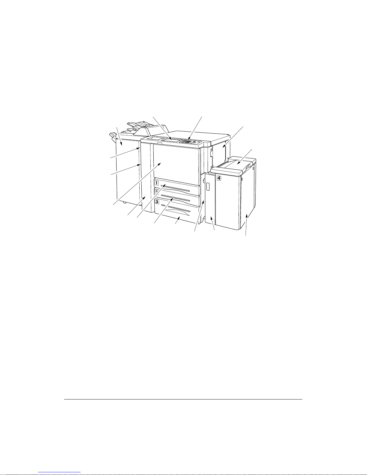
External Machine
Finisher / Finisher-
Folder (option)
Power switch
Left side cover
(not shown)
Front door
Left door
LCD touch screen
Tray 1
Tray 2
Right side door (not shown)
Tray 3
Control panel
LCT left side
door
Multi-sheet
bypass tray
LCT top door
Tray 4 : Large capacity
tray (8.5 x 11) (option)
1 Multi-sheet bypass tray used for small quantity printing onto plain paper or special paper.
2 LCT top door opens to allow loading paper.
3 Tray 4: Large capacity tray (8.5 x 11) option holds 4,000 sheets.
4 LCT left side door opens to allow removal of mishandled paper.
5 Right side door opens to allow removal of mishandled paper.
6 Tray 3 (universal tray) is user adjustable and holds 1,000 sheets of either 11"x17"/8.5"x14"/
8.5"x11"R or 5.5"x8.5".
7 Tray 2 (universal tray) is user adjustable and holds 500 sheets of either 11"x17"/8.5"x14"/
8.5"x11"R or 5.5"x8.5".
8 Tray 1 (universal tray) is user adjustable and holds 500 sheets of either 11"x17"/8.5"x14"/
8.5"x11"R or 5.5"x8.5".
NOTE: Tray 1, 2, 3, and 4 are available for loading wide types of the regular sizes specified above.
9 Left door opens together with the front door to allow removal of mishandled paper.
10 Front door opens to the internal printer to allow clearing of mishandled paper and
replenishing of toner.
11 Left side cover opens to allow removal of mishandled paper.
12 Power switch turns printer power On/Off when pressed.
13 Trimmer unit (See next page.)
14 Trimmer stacker cover (See next page.)
15 Finisher / Finisher-Folder (option) sorts, staple-sorts, and groups into finished sets.
Finisher-Binder also folding or stapling & folding prints into booklet-styled sets.
16 LCD touch screen displays interactive operation screens.
17 Control panel controls printer operations.
Machine Information 3-5
Page 26
Machine Information
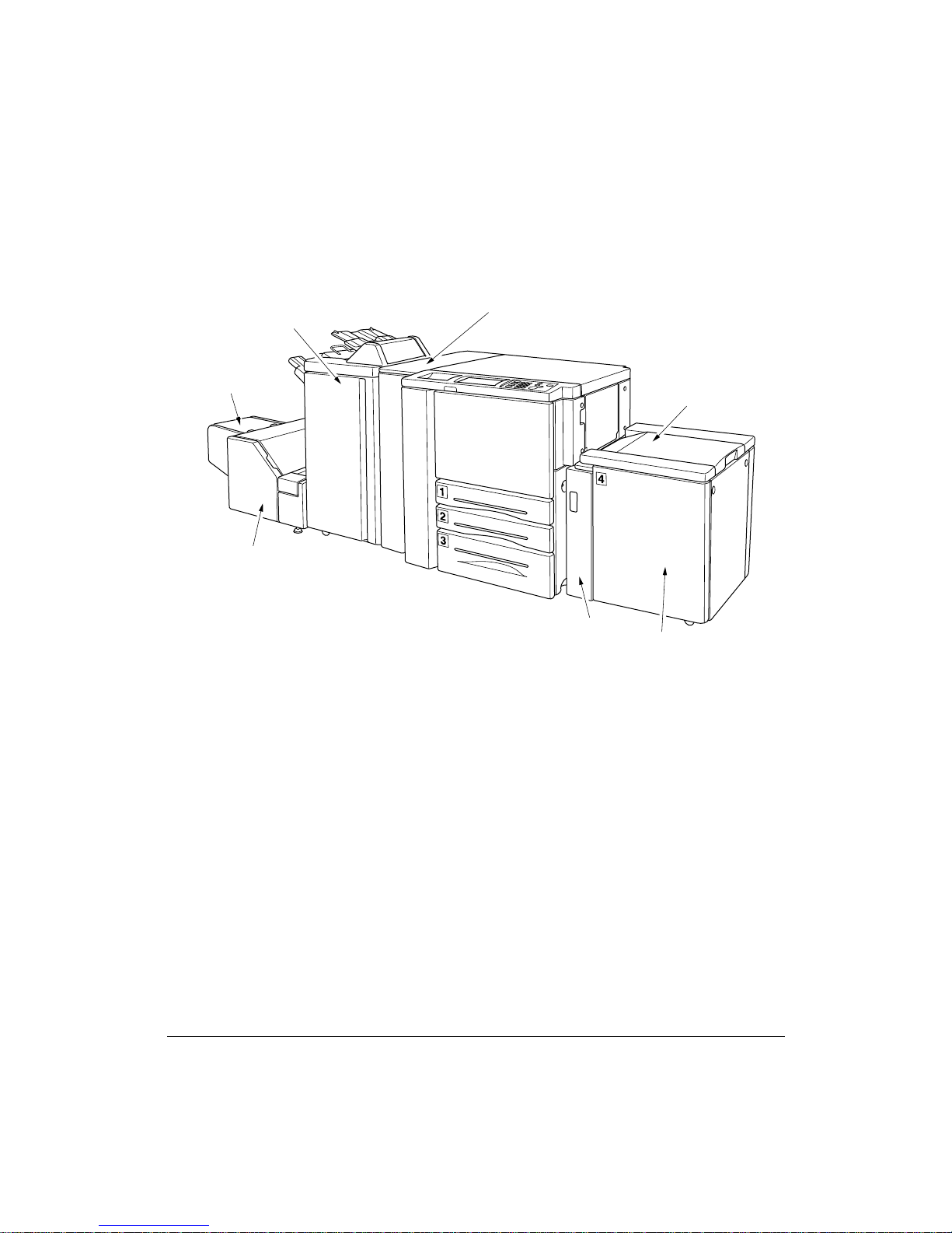
External Machine (continued)
Finisher-Folder (option)
Trimmer
stacker cover
Trimmer unit
(option)
Punch unit
(option)
LCT top door
LCT left side door
Tray 4: Large
capacity tray
(11 x 17) (option)
2 LCT top door opens to allow loading paper.
3 Tray 4: Large capacity tray (11 x 17) option holds 4,000 sheets.
4 LCT left side door opens to allow removal of mishandled paper.
13 Trimmer unit (option) trims the end of booklet.
14 Trimmer stacker cover opens to allow you to take out the finished sets.
15 Finisher / Finisher-Folder (option) sorts, staple-sorts, and groups into finished sets.
Finisher-Binder also folds or staples & folds prints into booklet-styled sets.
16 Punching unit (option) punches file holes in the output prints.
3-6 Machine Information
Page 27
Machine Information
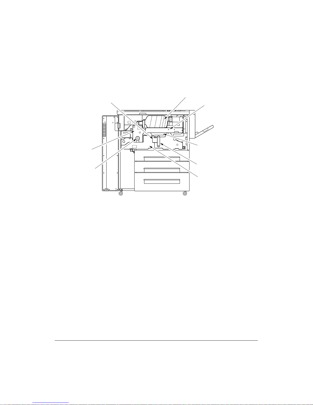
Internal Machine
iConveyance part
qToner bottle
wToner unit
uFixing part
yKnob
eDrum unit
rLever A
tConveyance/Fixing unit
1 Toner bottle holds toner and must be replaced when refilling toner.
2 Toner unit holds the toner supply.
3 Drum unit forms the print image.
4 Lever A can be moved to withdraw the conveyance fixing unit for removal of mishandled
paper.
5 Conveyance/Fixing unit passes the paper through the drum unit, and fuses the toner onto
the print paper, and must be withdrawn for removal of mishandled paper.
6 Knob can be turned to ease removal of mishandled paper from the fixing unit.
7 Fixing part
8 Conveyance part
Machine Information 3-7
Page 28

Machine Information
Standard Equipment
Main Body with 3 Paper Trays (500/500/1,000 sheets)
Automatic Duplex Unit (ADU)
Multi-Sheet Bypass Tray (150 Sheets)
Optional Equipment
Finisher (with 2 exit trays)
Secondary (sub) tray with 4 output types specified on Finisher Mode Selection Screen
(1) Face down non-sort exit
(2) Face up non-sort exit
(3) Face down group exit
(4) Face up group exit
Primary (main) tray with 4 output types specified by STAPLE SORT and SORT keys
on the Basic Screen and by the setting on the Finisher Mode Selection Screen. Face
up exit is not available.
(1) Sort exit
(2) Staple sort exit
(3) Non-sort exit
(4) Group exit
Finisher-Folder (with 3 exit trays and a cover sheet feeder option)
Secondary (sub) tray with 4 output types specified on Finisher Mode Selection Screen
(1) Face down non-sort exit
(2) Face up non-sort exit
(3) Face down group exit
(4) Face up group exit
Primary (main) tray with 4 output types specified by STAPLE SORT and SORT keys
on the Basic Screen and by the setting on the Finisher Mode Selection Screen. Face
up exit is not available.
(1) Sort exit
(2) Staple sort exit
(3) Non-sort exit
(4) Group exit
Booklet tray: Stapled and folded, or simply folded booklets are to be delivered onto this
tray.
Trimmer unit tray: This tray is attached to a trimmer unit (option) installed on the
stapler finisher-binder. Folded or stapled and folded trimmed booklets are delivered to
this tray.
3-8 Machine Information
Page 29

Machine Information
Optional Equipment (continued)
Punching Unit
Cover Sheet Feeder (Post Inserter)
Trimmer Unit
Large Capacity Tray (8.5 x 11) (4,000 sheets)
Large Capacity Tray (11 x 17) (4,000 sheets)
Expanded Memory Unit-64MB /128MB
Network Print Controller 75
PostScript 3 Enabler 75
Ethernet Card 75
Machine Information 3-9
Page 30
Machine Information
Optional Equipment (continued)
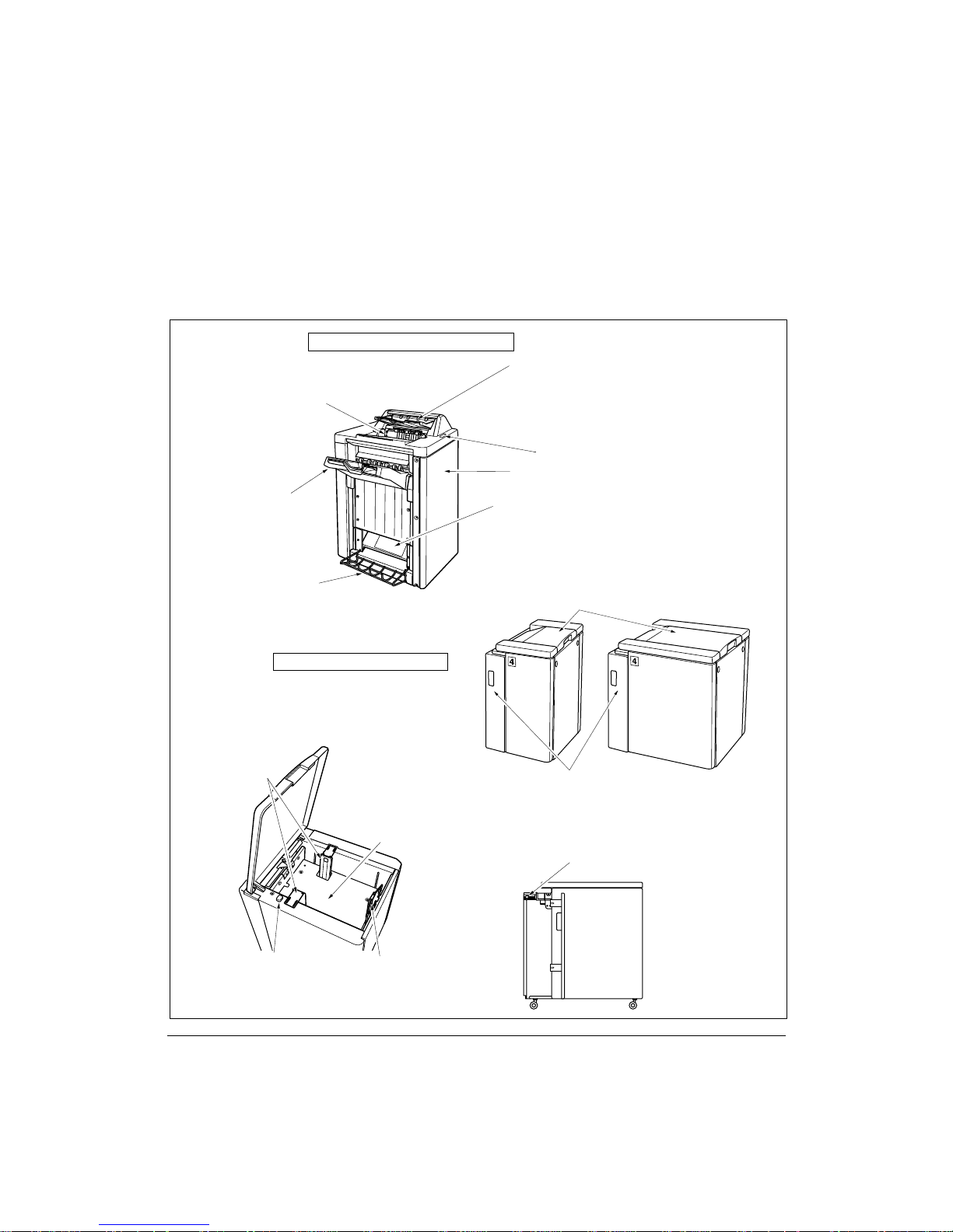
Finisher/Large Capacity Tray
Finisher / Finisher-Folder details
Cover sheet feeder (option):
Holds cover sheets for use in Cover
Sheet output mode or a printed set in
manual stapling mode.
Primary (main) tray:
Holds sets ejected in
q Sort mode (offset)
w Staple-sort mode
e Group mode (offset)
Secondary (sub) tray:
Holds sets ejected in
q Non-sort Face Down exit mode
w Non-sort Face Up exit mode
e Group Face Down exit mode
r Group Face Up exit mode
Manual staple control panel
Finisher door
Booklet mode outlet (Finisher-Folder only):
ejects finished printed sets when selecting
Folding mode or Stapling & Folding mode.
Booklet tray (Finsher-Folder only)
Large Capacity Tray details
Paper guides:
hold print paper to
fix its position.
Paper loading button:
is pressed to lower the bottom
plate to allow loading paper.
Bottom plate of the LCT:
goes up automatically when paper
supply becomes low, and goes
down when the paper loading
button is pressed.
8.5 x 11
style
11 x 17 style
Rear stopper:
fixes the rear end of
print paper.
LCT top door:
opens to load paper.
LCT left side door:
opens to allow removal of
mishandled paper.
LCT lever:
can be moved downward to ease
removal of mishandled paper.
11 x 17 style
11 x 17
style
3-10 Machine Information
Page 31

Machine Information
Optional Equipment (continued)
Trimmer Unit
Trimmer unit details
Trimmer unit tray:
slides to the left side
each time a trimmed
booklet is delivered.
Trimmer unit knob:
can be turned to ease removal
of mishandled paper.
Trimmer pressure
release lever:
opens to allow removal
of mishandled paper.
Finisher-Folder
Trimmer stacker cover:
opens to allow you to
take out the finished sets.
Trimmer stacker
Trash basket:
holds waste paper cut off
from the booklets.
Front-right cover:
opens to allow removal
of mishandled paper.
Front door:
opens to allow removal of
mishandled paper or waste
paper. (see details below)
NOTE:
DO NOT place heavy objects on the
trimmer stacker or apply any weight
on it, and DO NOT use it for storage.
Excessive weight applied to the
inside or outside of the trimmer
stacker will damage the equipment.
Machine Information 3-11
Page 32

Machine Information
Optional Equipment (continued)
Punching Unit
Punch Unit details
Punching unit knob:
can be turned to ease
removal of mishandled
paper.
Left lever:
opens downward to
allow removal of
mishandled paper.
Upper lever:
opens upward to allow
removal of mishandled
paper.
Right lever:
opens upward to allow
removal of mishandled
paper.
Trash basket:
holds waste paper punched
out.
Finisher/Punching unit
front door:
opens to remove mishandled
paper in Finisher or Punching
unit, to change the staple
cartridge and to remove
paper punched out.
3-12 Machine Information
Page 33

Machine Information
Site Requirements
3.9
12.65
(100)
(321)
Unit: inches (mm)
18.7
(475)
39.0
(990)
21.7
(550)
71.4
(1814)
Océ 750 + Finisher/Finsher-Folder + Large Capacity Tray (8.5 x 11)
92.3
(2344)
34.95
(887)
1
2
3
69.4
(1762)
34.95
(887)
11
2
3
15.75
(400)
15.2
(386)
4
20.9
(530)
Océ 750
3.9
(100)
39.0
(990)
37.4
(950)
37.4
(950)
72.6
(1845)
72.6
(1845)
30.5
(775)
4.7
(120)
Unit: inches (mm)
30.5
(775)
4.7
(120)
5.9
(150)
44.0
(1117)
(2829)
21.6
(550)
111.4
6.65
(169)
141.7
(3599)
34.95
(887)
24.6
(626)
30.3
(770)
3.9
(100)
39.0
(990)
37.4
(950)
72.6
(1845)
30.5
(775)
Océ 750 + Finisher-Folder + Punch Unit + Trimmer Unit + Large Capacity Tray (11 x 17)
NOTES:
1 Dimensions are in inches with millimeters included in parentheses.
2 The Finisher main tray of the Finisher / Finisher-Folder gradually goes down while printed material is
output. DO NOT allow any object to interfere with the operation of the tray on the left side of the finisher,
as interference may cause damage to the finisher.
Machine Information 3-13
Unit: inches (mm)
4.7
(120)
Page 34

Machine Information
Specifications
Product Name Océ 750 Printer
Engine Type Dual Beam Laser, Electrostatic
Engine Speed 75 pages per minute (400dpi)
55 pages per minute (600dpi)
Recommended Operating Environment 50°~86°F (10°~30°C); 10~80% Relative
Humidity
Warm Up Approx. 6 min. @68°(20°C); 50% Relative
Humidity
Voltage 208 ~ 240V AC ± 10%
Current 17.6A Dedicated line recommended
Frequency 50Hz/60Hz
Grounding Isolation recommended
Termination NEMA Type 6-20R receptacle
(250V, 2-pole, 3-wire, grounded)
Power Consumption Max. 3,840 VA (full option)
Noise Level (full system) Approx. 78 dB (A) or less, during printing
Main Body Safety Standard UL 1950; CSA 22.2 No. 950 -95
Laser Safety Standard FDA: CFR1040
3-14 Machine Information
Radio Interference FCC Rules part 15, sub-part B Class A
IC: ICES CSA C108.8 Class A
Toner Black, cartridge type
Paper Source Main body trays 1/2/3; 500/500/1,000 sheets
LCT tray 4; 4,000 sheets
Multi-sheet bypass tray; 150 sheets
Tray 1/2/3 user adjustable
Tray 4 adjusted by service
Paper Exit Tray 150 sheets (20 lb)
Specifications subject to change without notice.
Page 35

Machine Information
Specifications (continued)
Paper Weight 20 lb~24 lb bond recommended
Machine Weight 572 lb (260 kg)
Machine Dimensions Main Body
(Max. range: 16 lb~45 lb in 2-2 mode
16 lb~110 lb (200g/m
2
thick paper) in 1-1mode
OHP sheet, Transparency, Labels, Tab, 3-hole
Options Finisher / Finisher-Folder
Cover Sheet Feeder (Post Inserter)
Trimmer Unit
Large Capacity Tray (LCT) (8.5 x 11)
Large Capacity Tray (LCT) (11 x 17)
Expanded Memory Unit ( 64MB)
Network Print Controller
PostScript Unit
Network Board
+110 lb (50 kg) w/Stapler-Finisher
+66 lb (30 kg) w/Large Capacity Tray
Width: 34.9 in. (887mm)
Depth: 30.5 in. (775mm)
Height: 39.0 in. (990mm)
Stapler-Finisher (Finisher / Finisher-Folder)
Width: 21.4 in. (544mm)
Depth: 25.8 in. (656mm)
Height: 43.1 in. (1095mm)
Cover Sheet Feeder (Post Inserter)
Width: 13.0 in. (330mm)
Depth: 18.0 in. (456mm)
Height: 4.7 in. (120mm)
Trimmer Unit
Width: 44.0 in. (1117mm)
Depth: 23.8 in. (604mm)
Height: 22.1 in. (562mm)
Punching Unit
Width: 6.7 in. (169mm)
Depth: 26.0 in. (660mm)
Height: 39.0 in. (990mm)
(128MB)
Specifications subject to change without notice.
Machine Information 3-15
Page 36

Machine Information
Specifications (continued)
Automatic Duplex Unit (ADU) Paper size: 11"x17", 8.5"x14", 8.5"x11",
5.5"x8.5"
Paper weight: 16~45 lb
Paper curl limit: 20 mm or less
Non-stack type
Stapling (Finisher/Finisher-Folder) Power source: Main body
Non-sort/Sort/Group mode:
500 sheets 5.5"x8.5"R
3000 sheets 8.5"x11"/R
1500 sheets 11"x17", 8.5"x14"
Size 11"x17" ~ 5.5"x8.5"R
Staple-sort mode: 1000 sheets*
Size 11"x17" ~ 8.5"x11"/R, 5.5"x8.5"
* Variable according to the number of pages to
be stapled. See p. 4-4 for detail.
Folding/Stapling & Folding mode w/Finisher-
Binder - 100 sheets*
Size 11"x17", 8.5"x14", 8.5"x11"R, A4R
(8.27"x11.69", 210mmx297mm)
* The maximum number of sheets varies
depending on pages of a booklet and
selecting either the Folding or Stapling &
Folding. See p. 4-5.
Cover Sheet Feeder (Post Inserter) Paper size : 11"x17", 8.5"x14", 8.5"x11",
3-16 Machine Information
Staple Cartridge 5000 staples/cartridge
8.5"x11"R, 5.5"x11", 5.5"x11"R, A4, A4R
(8.27"x11.69", 210mmx297mm)
Paper weight in cover sheet mode: 13 ~ 110 lb
(200g/m2 thick paper)
Paper weight in manual staple: 16 ~ 24 lb
Specifications subject to change without notice.
Page 37

Machine Information
Specifications (continued)
Trimmer Unit Paper size : 11"x17", 8.5"x14", 8.5"x11"R, A4R
Punching Unit Paper size: 11"x17", 8.5"x11"
(8.27"x11.69", 210mmx297mm)
Paper weight : 16 ~ 45 lb
*One 110 lb cover paper (200g/m2 thick paper)
is available.
Number of trimmed sheets :
3 sheets max. with Folding mode
16 sheets max. with Stapling & Folding mode
(15 sheets max. when using a thick cover)
Trimmed width : 10 mm max.
Stack capacity : 512 sheets max.
* The maximum number of sheets varies,
depending on the number of pages in the
booklet and whether Folding or Stapling &
Folding is selected.
Power source: supply from outlet
Paper weight: 16~45 lb
Number of hole: 3 holes
Hole diameter: 0.35" ± 0.020" (8mm ± 0.5mm)
Hole pitch: 4.252" ± 0.020" (˙mm ± 0.5mm)
Weight: 77 lb (35 kg)
Power source: supply from outlet
Large Capacity Tray (8.5x11) Plain paper (16~110 lb (200g/m2 thick paper))
Paper size: 8.5"x11", A4
Dimensions: Width 16.9 in (430 mm)
Depth 25.2 in (639 mm)
Height 27.2 in (690 mm)
Weight: 66 lb (30 kg)
Power source: supply from main body
Large Capacity Tray (11x17) Paper type: Plain paper (16~110 lb (200g/m
thick paper))
Paper size: 11"x17", 8.5"x14", 8.5"x11",
8.5"x11"R, A3, B4, A4, A4R, F4
Dimensions: Width 26.4 in (670 mm)
Depth 25.2 in (639 mm)
Height 27.4 in (695 mm)
Weight: 92.4 lb (42 kg)
Power source: supply from main body
Specifications subject to change without notice.
Machine Information 3-17
2
Page 38

Page 39

Section 4: Media Information
Main Body Trays.......4-2
Large Capacity Tray (8.5 x 11) (Option).......4-3
Large Capacity Tray (11 x 17) (Option).......4-3
Automatic Duplex Unit.......4-4
Multi-Sheet Bypass Tray and Tab Sheets.......4-4
Finisher / Finisher-Folder (Option).......4-5
Primary (Main) Tray.........4-5
Secondary (Sub) Tray.........4-5
Finisher-Binder Booklet Tray.........4-6
Cover Sheet Feeder (Post Inserter) (Option).......4-7
Paper in Punching Unit (Option).......4-7
Paper in Trimmer Unit (Option).......4-7
Paper Supply Message.......4-8
Paper Weight Compatibility Chart.......4-9
Media Information 4-1
Page 40

Media Information
Main Body Trays
Standard Paper Size: 11"x17", F4, 8.5"x14", 8.5"x11", 8.5"x11"R, 5.5"x8.5", A3, B4, A4,
A4R, B5, B5R, A5 (user-adjustable)
NOTES: • F4: 8"x13", 203mm x 330mm
A3: 11.69"x16.54", 297mm x 420mm
B4: 10.11"x14.33", 257mm x 364mm
A4: 8.27"x11.69", 210mm x 297mm
B5: 7.17"x10.11", 182mm x 257mm
A5: 5.85"x8.27", 148mm x 210mm
• 5.5"x8.5"/A5 print paper is available in portrait orientation loading only.
Wide Paper Size: 11"x17"W, 8.5"x11"W, 8.5"x11"WR, 5.5"x8.5"W, A3W, B4W, A4W,
A4WR, B5W, A5W (user-adjustable)
NOTES: • 8.5"x14"W print paper is not available.
• Wide paper size setting for each tray can be made in the Key Operator mode. See p. 8-16 ~ p. 8-
17.
Paper Weight: General tray; 16~24 lb
Tray specified in Thick 1; 25~45 lb
Tray specified in Thick 2; 46~110 lb (200 g/m2 thick paper)
(1-1 or 2-1 print mode only)
NOTE: Paper type setting (Thick 1 or Thick 2) for each tray can be made in the Key Operator mode.
See p. 8-16 ~ p. 8-17.
Total Paper Capacity: 2,150 sheets, including 150-sheet Multi-Sheet Bypass Tray
Tray 1/2: 500 sheets 20lb/ user-adjustable to any standard/wide size from 11"x17"/W~5.5"x8.5"/W
Tray 3: 1,000 sheets 20lb/ user-adjustable to any standard/wide size from 11"x17"/W~5.5"x8.5"/W
4-2 Media Information
Page 41

Media Information
Large Capacity Tray (8.5 x 11) (Option)
Standard Paper Size: 8.5"x11" or A4 (service-adjustable)
Wide Paper Size: 8.5"x11"W or A4W (service-adjustable)
Paper Weight: 16~24 lb
LCT in Thick 1: 25~45 lb
LCT in Thick 2: 46~110 lb (200 g/m2 thick paper) in 1-1 mode only
NOTE: Paper type setting (Thick1 or Thick 2) for LCT can be made in the Key Operator mode.
See p. 8-16 ~ p. 8-17.
Total Paper Capacity: 6,150 sheets, including three Main body trays, 150-sheet
MultiSheet Bypass Tray and 4,000-sheet optional LCT.
Tray 4 (LCT): 4,000 sheets 20 lb/ fixed to standard/wide size 8.5"x11"/W or A4/W
Large Capacity Tray (11 x 17) (Option)
Standard Paper Size: 11"x17", F4, 8.5"x14", 8.5"x11", 8.5"x11"R, A3, B4, A4, A4R
(service-adjustable)
Wide Paper Size: 11"x17"W, F4W, 8.5"x14"W, 8.5"x11"W, 8.5"x11"WR, A3W, B4W,
A4W, A 4WR (service-adjustable)
Paper Weight: 16~24 lb
LCT specified in Thick 1; 25~45 lb
LCT specified in Thick 2; 46~110 lb (200 g/m2 thick paper)
(1-1 or 2-1 copying only)
NOTE: Paper type setting (Thick1 or Thick 2) for LCT can be made in the Key Operator mode. See p. 13-24
~ p. 13-25.
Total Paper Capacity: 6,150 sheets, including three Main body trays and 150-sheet
Tray 4 (LCT): 4,000 sheets 20 lb/ fixed to standard/wide size 11"x17"/W, F4/W, 8.5"x14"/W,
8.5"x11"/W, 8.5"x11"R/W, A3/W, B4/W, A4/W, or A4R/W
NOTE: Reliability and print quality are not guaranteed for all Special papers. Use only paper that is
recommended by Océ.
Multi-Sheet Bypass Tray
Media Information 4-3
Page 42

Media Information
Automatic Duplex Unit
Standard Paper Size: 11"x17"~5.5"x8.5"
Wide Paper Size: 11"x17"W~5.5"x8.5"W
NOTE: 5.5"x8.5"/W print paper is available in portrait orientation feeding only.
Paper Weight: 16~45 lb
Multi-Sheet Bypass Tray
Loading Paper Size:
Max. 12.36"x17.52" (314mm x 445mm) ~ Min. 3.94"x5.83" (100mm x 148mm)
Specified Size Automatically: 11"x17", 8.5"x14", 8.5"x11", 8.5"x11"R, 5.5"x8.5", 5.5"x8.5"R,
A3, B4, A4, B5, B5R
Specified Size Manually / STD Size (Special) : F4, A4R, A5, A5R
Specified Size Manually / Wide Paper:11"x17"W, 8.5"x11"W, 8.5"x11"WR, 5.5"x8.5"W,
5.5"x8.5"WR, A3W, B4W, A4W, A4WR, B5W,
B5WR, A5W, A5WR
Paper Weight: 16~45 lb (duplex (1-2 and 2-2) print mode)
Special (OHP transparencies, labels, hole punch, rag content)
Multi-Sheet Bypass Tray Capacity: 150 sheets 20 lb stacked: single feed special stock
NOTE: Reliability and print quality are not guaranteed for all Special papers. Use only paper that is
recommended by Konica.
4-4 Media Information
Page 43

Media Information
Finisher / Finisher-Folder (Option)
In-Bin Stapler Finisher / Finisher-Binder accepts LEDGER (11"x17"), LEGAL (8.5"x14")
and LETTER/R (8.5"x11"/R) standard/wide paper sizes (5.5"x8.5"R/W in Non-sort, Sort
or Group mode).
Primary (Main) Tray
In-Bin Stapler Finisher / Finisher-Folder (capacities at 20lb, unless otherwise
indicated)
Non-sort/Sort/Group mode:
500 sheets 5.5"x8.5"/5.5"x8.5"W, 5.5"x8.5"R/5.5"x8.5"WR (A5/A5W, A5R/A5WR)
3,000 sheets 8.5"x11"/8.5"x11"W, 8.5"x11"R/8.5"x11"WR (A4/A4W, A4R/A4WR,
B5/B5W, B5R/B5WR)
1,500 sheets 11"x17"/11"x17"W, 8.5"x14" (A3/A3W, B4/B4W)
Staple-sort mode:
1,000 sheets* 11"x17"/11"x17"W, 8.5"x14", 8.5"x11"/8.5"x11"W, 8.5"x11"R/
8.5"x11"WR
NOTE: (*)Variable according to the number of pages to be stapled. See the table below.
Paper Capacity for Staple-sort mode of Finisher/Finisher-Folder
11"x17"/11"x17"W (A3/A3W)
No. of prints
2~9
2 staples
50 sets
10~20
21~30
31~40
41~50
(for the same size only)
1 staple
50 sets
50
30
25
20
50
30
25
20
8.5"x14", 8.5"x11"/8.5"x11"W,
8.5"x11"R/8.5"x11"WR (B4/B4R,
A4/A4W, A4R/A4WR, B5/B5W, A5/A5W)
2 staples
100 sets
50
30
25
20
1 staple
100 sets
50
30
25
20
Secondary (Sub) Tray
In-Bin Stapler Finisher / Finisher-Folder (capacities at 20lb, unless otherwise
indicated)
200 sheets; max. 12.36"x17.52" (314mmx445mm) ~ min. 3.94"x5.83" (100mmx148mm)
CAUTION:
When the selected print quantity exceeds the Finisher’s maximum capacity, remove the printed sheets
while paper is exiting to avoid paper mishandling.
Media Information 4-5
Page 44

Media Information
Finisher / Finisher-Folder (Option) (continued)
Finisher / Finisher-Folder Booklet Tray
Folding mode:
Standard Paper Size : 11"x17", 8.5"x14", 8.5"x11"R, A3, B4, A4R
Wide Paper Size : 11"x17"W, 8.5"x11"WR, A3W, B4W, A4WR
Paper Weight : 16 ~ 24 lb
Number of Folded Sheet : 3 sheets max.
Booklet Tray Capacity : Approx. 100 sheets max.
33 sets max. of 3-sheet-folded booklet
(33 x 3 = 99 sheets)
50 sets max. of 2-sheet-folded booklet
(50 x 2 = 100 sheets)
Stapling & Folding mode:
Standard Paper Size : 11"x17", 8.5"x14", 8.5"x11"R, A3, B4, A4R
Wide Paper Size : 11"x17"W, 8.5"x11"WR, A3W, B4W, A4WR
Paper Weight : 16 ~ 24 lb
Number of Folded Sheet : 16 sheets max. (using 20lb paper only)
15 sheets max. (a thick cover paper included)
Booklet Tray Capacity : Approx. 100 sheets max.
20 sets max. of 5-sheet-folded booklet
(20 x 5 = 100 sheets)
10 sets max. of 10-sheet-folded booklet
(10 x 10 = 100 sheets)
6 sets max. of 16-sheet-folded booklet
(6 x 16 = 96 sheets)
CAUTION:
Inside the Booklet mode outlet is the roller drive unit. DO NOT put your hand into the roller drive unit
when removing folded or stapled & folded sheets; otherwise you may be injured.
4-6 Media Information
Page 45

Media Information
Cover Sheet Feeder (Post Inserter) (Option)
Standard Paper Size : 11"x17", 8.5"x14", 8.5"x11", 8.5"x11"R, 5.5"x8.5", A3, B4, A4,
A4R, B5, A5
Wide Paper Size : 11"x17"W, 8.5"x11"W, 8.5"x11"WR, 5.5"x8.5"W, A3W, B4W,
A4W, A4WR, B5W, A5W
Paper Weight in Cover Sheet Mode : 13 ~ 110 lb (200g/m
Paper Weight in Manual Staple : 16 ~ 24 lb
Paper in Punching Unit (Option)
Paper Size : 11"x17", 8.5"x11"
Paper Weight : 16 ~ 45* lb
Number of Punch Holes : 3
Hole Diameter : 0.315" ± 0.020" (8.0 mm ± 0.5 mm)
Hole Pitch : 4.252 " ± 0.020" (108 mm ± 0.5 mm)
* : Some 45 lb paper types may not be punched easily.
NOTE: Punching special paper will cause machine trouble.
Paper in Trimmer Unit (Option)
2
thick paper)
Trimming mode:
Paper Size : 1"x17", 8.5"x14", 8.5"x11"R, A4R
Paper Weight : 16 ~ 24 lb (One 46 ~ 110 lb sheet only used as a cover)
Number of Trimmed Sheet
: 3 sheets max. with Folding mode
16 sheets max. using 20 lb paper only with Stapling &
Folding mode
15 sheets max. using one cover sheet with Stapling &
Folding mode
Trimming Width : 10 mm max.
Trimmer Unit Tray Capacity
: Approx. 512 sheets max.
100 sets max. of 2~5-sheet-folded booklet
50 sets max. of 6~10-sheet-folded booklet
32 sets max. of 11~16-sheet-folded booklet
Media Information 4-7
Page 46
Media Information
Paper Supply Message
When the paper size specified by the driver is not set in the tray or when paper runs out,
the following message is displayed on the screen. In addition, the tray size indicator and
the paper supply indicator will blink in the Tray size area of the screen.
The paper types specified for the main body trays and LCT (trays 1/2/3/4) are set in the
Key Operator mode. The following eleven paper types can be displayed:
Main body trays
[THICK1] [THICK2] [THIN] [USER] [TABPAPER]
[NORMAL] [RECYCLE] [COLOR] [SPECIAL] [FINE] [SEAL]
Paper types specified for the Multi-sheet bypass tray are specified by selecting the key
on the Paper Type/Size Selection Screen. The following six paper types can be
displayed:
Multi-sheet bypass tray
[THICK] [THIN] [TAB] [OHP] [TRACE] [USER]
4-8 Media Information
Page 47

Media Information
Paper Weight Compatibility Chart
Main Body Trays
Large Capacity Tray
Automatic Duplex Unit
Multi-Sheet Bypass Tray
Finsher/Finisher-Folder
Post Inserter 75
Punch Unit 75
Trimmer Unit 75
All Trays: 16 ~ 24 lb
Tray specified in Thick 1: 25 ~ 45 lb
Tray specified in Thick 2: 46 ~ 110 lb
(200g/m
2
thick paper) in 1-1 or 2-1 only
16 ~ 24 lb
LCT specified in Thick 1: 25 ~ 45 lb
LCT specified in Thick 2: 46 ~ 110 lb
(200g/m
2
thick paper) in 1-1 or 2-1 only
16 ~ 45 lb
16 ~ 45 lb
13 ~ 110 lb (200g/m
13 ~ 110 lb (200g/m
2
thick paper)
2
thick paper)
16 ~ 45* lb
16 ~ 45 lb
(One 110 lb sheet only used as a cover.)
*: Some 45 lb paper types may not be punched easily.
NOTE: Reliability and print quantity are not guaranteed for all Special papers. Use only paper that is
recommended by Konica.
Media Information 4-9
Page 48

Page 49

Section 5: Printing Operations
Introduction.......5-2
Wake Up Screen.........5-2
Warm Up Screen.........5-2
Control Panel.......5-3
The Basic Screen.......5-3
Check Mode Message.......5-4
Check Mode Screen.........5-4
Reservation List.......5-5
Screen Display.........5-5
Help Mode.......5-5
Change Job Order.......5-6
Job Deletion.......5-7
Previous Job List.......5-8
Change Setting.......5-9
Print Size..... 5-10
Selecting Paper Type/Size for Multi-Sheet Bypass Tray.......5-10
Controller Screen..... 5-11
Auto Low Power Mode..... 5-12
The Counter List..... 5-13
View the Counter List.......5-13
Print the Counter List.......5-13
Weekly Timer Function..... 5-14
Timer Interrupt.......5-14
Printing Operations 5-1
Page 50

Printing Operations
Introduction
The Océ 750 printer control panel screen described in this section includes the LCD
display screen, basic control panel operations and a sampling of screen messages you
will encounter when using this printer.
Technical details of the LCD as well as a complete Message List can be found in the
Service Manual.
Wake Up Screen
The Wake Up Screen displays immediately after the printer is turned on. Then a Waitfor-a-while screen displays while the printer initializes memory data.
The sequence is as follows:
[OFF Power]
[Power ON]
[Konica
Wake Up Screen]
[Konica
Warm Up Screen]
Warm Up Screen
When initialization is completed, the Warm Up Screen displays with several animated
pictures corresponding to the fixing temperature. Once the Warm Up Screen changes,
as a result of normal user operations, you will not return to the Warm Up Screen again.
5-2 Printing Operations
Page 51

Printing Operations
Control Panel
CHECK
HELP
STOP / PAUSE
TIMER
POWER SAVER
ON / OFF
COUNTER
CLEAR QTY.
START
The control panel is user-friendly and easy to operate. On the right are the Weekly Timer
indicator and buttons to select [POWER SAVE ON/OFF], [STOP/PAUSE] and [START] keys.
The keypad is used by service personnel to perform technical functions. On the left are
keys for displaying the Check Mode and the Help Mode. The LCD screen at the far left
displays machine status, printing status and Help information.
The Basic Screen
The Basic Screen consists of a Message Area, Icon area and Job Control area. The
Basic Screen normally looks like the sample screen below. The message area at the top
displays two lines of information, each with a maximum of 40 alphanumeric characters.
The icon area in front of ADD TONER, PM CALL and MEMORY displays controller
status, such as, [WAITING], [INITIAL], [PRINT], [ERROR], and [IDLE].
This portion
of the screen
displays the
status
regarding
Job
Control
Printing Operations 5-3
Page 52

Printing Operations
Check Mode Message
When the temporary stop function is specified by the driver, the following message
displays on the Basic Screen.
When the [CHECK] key is pressed the Printer Check Screen will be displayed.
When the [START] key is pressed, printing will begin.
Check Mode Screen
When you press the [CHECK] key on the control panel, the Printer Check Mode Screen
displays as shown below. You may view the list, which is displayed in real time.
Touch the CHANGE SETTING key to display the Change Setting Screen.
Make setting changes and press OK.
Touch the PROOF COPY and output only one set of the print quantity amount, whether a
change has been made or not. Then press the [START] key to print out the remaining
quantity.
5-4 Printing Operations
Page 53

Printing Operations
Reservation List
Screen Display
The reservation list screen displays after the main power switch is turned on and warm
up is completed. When no Job is reserved, the screen looks like the screen shown
below. Notice that the JOB PRIORITY key and the JOB DELETE key are shaded, which
means they do not function.
Help Mode
Use the [HELP] key to access information about the current screen mode and to learn
about setting procedures. The [HELP] key can be pressed from any screen except Key
Operator Screens.
No Jobs Reserved
The Help Screen includes the Help menu icon in the center. When the HELP MENU key
is touched, the Help Menu Screen displays a list of all of the printer functions. When a
function item is touched, the Help Screen displays information specific to that topic.
The KEY OPERATOR MODE key is also provided in the lower left position of the Help
Screen. When touched, the Key Operator Password Entry Screen will be displayed to
access the Key Operator mode. See p. 8-2.
Control panel contrast key Weekly Timer key
CHECK HELP
Printing Operations 5-5
Page 54

Printing Operations
Change Job Order
When a reserved Job is listed on the screen, you may select the Status display key to
highlight the Job and then press the Job Priority key to change the order of priority.
(See screens below.)
Screen without Job Priority change
Screen with Job Priority change
Note that it is not possible to change the priority of a Job in the process of printing.
5-6 Printing Operations
Page 55

Printing Operations
Job Deletion
Touch the Status key to highlight a Job, then touch the JOB DELETE key to delete the
Job. Before the Job is deleted, a pop up screen allows you to confirm the deletion.
Touch YES to delete the Job. Touch NO to keep the Job. Keep in mind that a Job in
progress and a Job in data transmission cannot be deleted.
Job Selected for Deletion
Pop Up Screen Confirmation
Screen Displayed After Deletion
Printing Operations 5-7
Page 56

Printing Operations
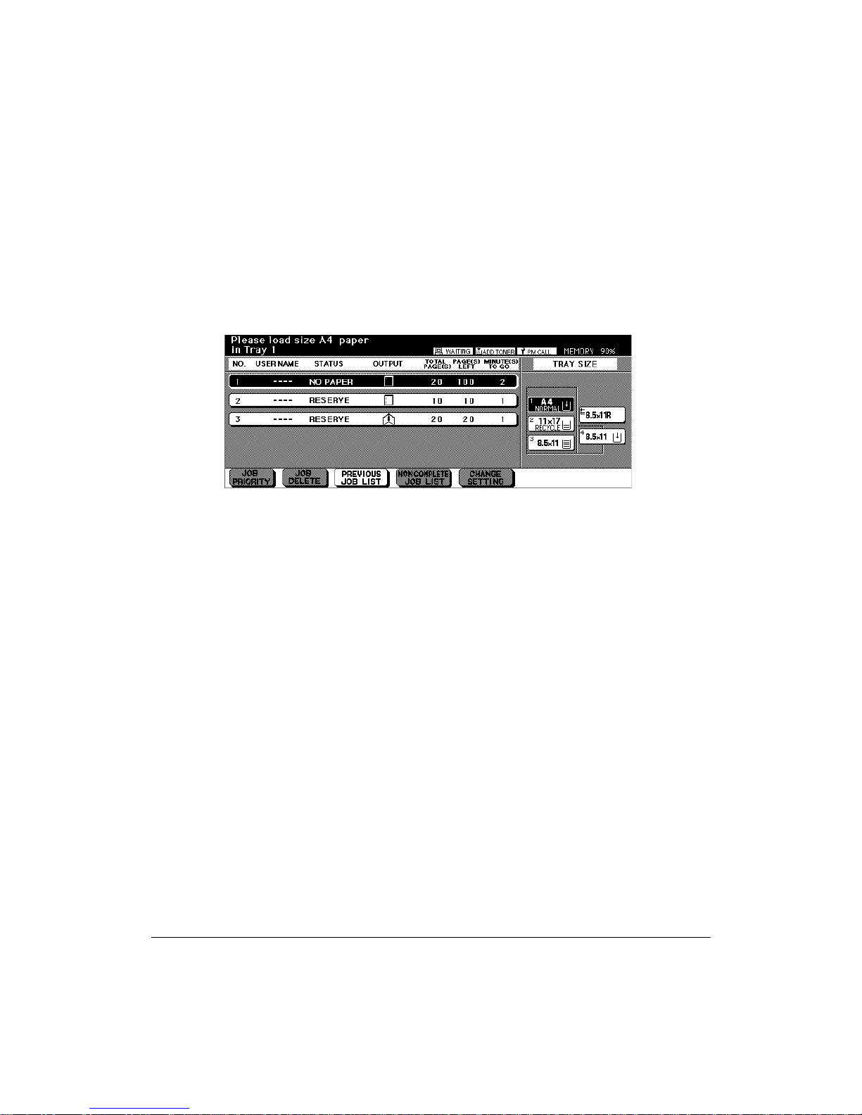
Previous Job List
The previous Job list can be displayed by pressing the Previous Job List key at the
bottom of the screen. The sample below shows that four previous Jobs per screen can
be displayed. If more Jobs are able to be displayed, up and down arrow keys will
become available at the bottom of the screen. Use these keys to scroll back and forth to
display a maximum of sixteen Jobs, four Jobs per screen. When you touch OK, the
Reservation List screen displays.
5-8 Printing Operations
Page 57

Printing Operations
Change Setting
While printing in the Staple Sort mode, printing will stop and the machine will go into the
wait mode in the event the machine detects mixed originals with different widths that
cannot be stapled. The CHANGE SETTING key enables you to change the setting and
restart the Job. Touch the CHANGE SETTING key, change the setting, then touch OK.
When the Reservation List screen reappears, press [START] key to restart the Job.
Waiting screen alternately displays "Print on Letter if you restart the Job."
Touch "OFF" to change the mode.
After changing the setting, the job is ready to be printed.
Printing Operations 5-9
Page 58

Printing Operations
Print Size
Selecting Paper Type/Size for Multi-Sheet Bypass Tray
1 Open the Multi-sheet bypass tray, and load the print paper on the tray. See p. 7-4, p.
7-7 for further details.
2 Touch Bypass key, then touch PAPER TYPE/SIZE. The Paper Type/Size Selection
Screen will be displayed.
3 Touch the desired key.
Basic Screen Paper Type/Size Selection Screen
• When Thick, Thin, Tab paper, OHP, Trace, or User is highlighted, a printing job will be
performed conforming to the selected paper type.
If no paper type indication is needed, touch the highlighted key to clear the selection
in the TYPE area.
The selection will show on the Basic Screen when restored.
NOTE: • When selecting Thick, THICK 1 will be displayed on Bypass key of the Basic Screen.
• When selecting TAB, AMS is automatically selected. The STD size (special) and Non STD size
cannot be selected, and the loading print paper cannot be fed on 1-2 or 2-2 printing.
5-10 Printing Operations
Page 59

Printing Operations
Controller Screen
The Controller screen displays separate sections for Messages, Icons, the Main Menu,
and a Main window.
• The Message section displays the characters sent from the controller and include a
max. of 40 digits x 2 lines.
• The Icon area displays engine status icons relating to Add Toner/PM Call, Vacant
Memory Capacity.
• The Main Menu area displays the Controller setting menu in 16 digits max.
• The Main Window area displays the item selected from the main menu. A max. of 4
digits can be displayed on a given screen. Four control keys are displayed at the
bottom of the screen. Use the up and down arrow keys to scroll through the menu.
• The Sub-window of the item selected from the main menu displays up to 8 items
using a maximum of 16 digits. A maximum of 4 control keys are displayed at the
bottom of the sub-window. Use the up and down arrow keys to scroll through the
menu.
Printing Operations 5-11
Page 60

Printing Operations
Auto Low Power Mode
Auto Low Power mode enables you to conserve energy by maintaining a lower fixing
temperature during periods of printer inactivity.
Auto Low Power mode automatically lowers the power after a specified period of printer
inactivity as specified in the Key Operator mode. The Auto Low Power function can be
set to 5 minutes/ 10 minutes/ 15 minutes/ 30 minutes/ 60 minutes/ 90 minutes/ 120
minutes/ 240 minutes. Initially, the mode is set to function after 15 minutes of printer
inactivity. The [POWER SAVER ON/OFF] LED goes on.
The Low Power mode screen is similar to the Reservation List Screen but with darker
backlighting to save energy consumption.
5-12 Printing Operations
Page 61

Printing Operations
The Counter List
This function allows you to view the current status of items shown on the touch panel,
such as Total Counter and Counter Start Date.
View the Counter List
1 To display the Counter List, press [P (COUNTER)].
2 After viewing the Counter List, touch EXIT to return to the Basic Screen.
Counter List Screen
Print the Counter List
1 Press [P (COUNTER)] to display the Counter List Screen.
2 Touch Counter list output. The Basic Screen will be displayed.
3 Touch the desired tray key to select the print size.
4 Press [START].
The counter list will be printed out, and the Management list mode will be released.
Printing Operations 5-13
Page 62

Printing Operations
Weekly Timer Function
When the printer is using the weekly timer function, the TIMER indicator on the right side
of the control panel is lit.
Important: When the TIMER indicator is lit, the printer will automatically be turned off. Do
not turn it off by pressing power switch.
Timer Interrupt
When the TIMER indicator light is on and other indicators are off, printing is unavailable.
When pressing the [POWER SAVER ON/OFF] key, the Basic Screen will be displayed
along with the messages shown below.
Please wait
Printer is warming up
Timer interrupt mode
Enter password
NOTE: The Timer Interrupt password is set by the Key Operator, not at the factory.
5-14 Printing Operations
Page 63

Printing Operations
Weekly Timer Function (continued)
Timer Interrupt (continued)
1 Enter a 4-digit number Timer Interrupt password using the keypad on the control
panel.
If an invalid password is entered, enter a valid 4-digit password.
Timer interrupt mode
Enter password ✻✻✻✻
2 Press [START].
Input print time
0 hour(s) 05 minute(s)
3 Enter a 1-digit hour (ex. 3 hour is 3) using the keypad on the control panel. (0 ~ 9)
4 Press [START].
Input print time is
3 hour(s) 05 minute(s)
5 Enter a 2-digit minutes (ex. 7 minutes is 07) using the keypad on the control panel.
(05 ~ 60)
Input print time is
3 hour(s) 07 minute(s)
6 Press [START].
Printing is available until the set time is up.
7 When Timer Interrupt is finished, press [POWER SAVER ON/OFF].
The Shut-Off Setting Screen will be displayed.
Printing Operations 5-15
Page 64

Page 65

Section 6: Output Modes
Finisher / Finisher-Folder Specifications.......6-2
Finisher Type.........6-2
Primary (Main) Tray.........6-2
Secondary (Sub) Tray.........6-3
Booklet Tray (Finisher-Folder only).........6-3
Cover Sheet Feeder (Post Inserter).........6-3
Punching Unit.........6-4
Trimmer Unit Tray (Finisher-Folder only).........6-4
Non-Sort Mode Using Primary (Main) Tray.......6-5
Sort Mode Using Primary (Main) Tray.......6-6
Staple-Sort Mode Using Primary (Main) Tray.......6-7
Folding, Stapling & Folding and Trimming Modes.......6-8
Punching Mode..... 6-10
Cover Sheet Feeder (Post Inserter)..... 6-11
Manual Stapling..... 6-12
Output Mode for Machine without Finisher..... 6-14
Output Modes 6-1
Page 66

Output Modes
Finisher / Finisher-Folder Specifications
Use only paper that is recommended by Konica and stored under specified conditions.
Special stock is not guaranteed for reliability or print quality. Multi-sheet bypass tray, and
Transparency interleaving are incompatible with finisher use. This Finisher also
accommodates wide paper sizes in addition to the standard sizes described below.
Finisher Type
❒ Primary (Main) Tray with built-in 2 stapling: moving tray type
Secondary (Sub) Tray
Booklet Tray
Cover Sheet Feeder (option)
Trimmer Unit(option) (Finisher-Folder only)
Primary (Main) Tray
Non-Sort Mode
❒ Paper size: 11"x17"~5.5"x8.5"
❒ Paper weight: 16~24 lb; Special stock (65 lb (176 g/m
punch, rag content)
❒ Paper capacity for 20 lb: 500 sheets 5.5"x8.5"
3,000 sheets 8.5"x11", 8.5"x11"R
1,500 sheets 11"x17", 8.5"x14"
Sort Mode/Group Mode
❒ Paper size: 11"x17"~5.5"x8.5"
❒ Paper weight: 16~24 lb
❒ Paper capacity for 20 lb: 500 sheets 5.5"x8.5"
3,000 sheets 8.5"x11", 8.5"x11"R
1,500 sheets 11"x17", 8.5"x14"
Staple-Sort Mode
❒ Paper size: 11"x17", 8.5"x14", 8.5"x11"R, 8.5"x11"
❒ Paper weight: 16~24 lb
❒ Paper capacity for 20 lb: 1,000 sheets*
❒ Staple capacity: 50 sheets*2 (5.0mm thick or less)
❒ Staple position: See p. 6-6.
1
2
cover paper), transparency film, labels, hole
NOTES:
*1: Variable according to the number of pages to be stapled.
*2: Staple sheet capacity is changeable, and may be set to 45, 40 or 35 by your service representative.
6-2 Output Modes
Page 67

Output Modes
Finisher / Finisher-Folder Specifications (continued)
Secondary (Sub) Tray
Non-sort and face down exit
Non-sort and face up exit
Group and face down exit
Group and face up exit
❒ Paper size: 11"x17"~5.5"x8.5"
❒ Paper weight: 16~24 lb
❒ Paper capacity for 20 lb: 200 sheets
Booklet Tray (Finisher-Folder only)
Folding Mode
❒ Paper size: 11"x17", 8.5"x14", 8.5"x11"R, A4R (8.27"x11.69", 210mmx297mm)
❒ Paper weight: 16~24 lb: Special stock (20 lb paper is recommended)
❒ Number of Folding sheet: 3 sheets max.
❒ Booklet tray capacity: Approx. 100 sheets max.
33 sets max. of 3-sheet-folded booklet
(33 x 3 = 99 sheets)
50 sets max. of 2-sheet-folded booklet
(50 x 2 = 100 sheets)
Stapling & Folding Mode
❒ Paper size: 11"x17", 8.5"x14", 8.5"x11"R, A4R (8.27"x11.69", 210mmx297mm)
❒ Paper weight: 16~24 lb; Special stock (20 lb paper is recommended)
❒ Number of Folding sheet: 16 sheets max. (using 20 lb paper only)
15 sheets max. (a thick cover paper included)
❒ Booklet tray capacity: Approx. 100 sheets max.
20 sets max. of 5-sheet-folded booklet
(20 x 5 = 100 sheets)
10 sets max. of 10-sheet-folded booklet
(10 x 10 = 100 sheets)
6 sets max. of 16-sheet-folded booklet
(6 x 16 = 96 sheets)
Cover Sheet Feeder (Post Inserter)
❒ Paper size: 11"x17", 8.5"x14", 8.5"x11", 8.5"x11"R, 5.5"x8.5", A4, A4R (8.27"x11.69",
210mmx297mm)
❒ Paper weight in cover sheet mode: 13~110 lb (200g/m2 thick paper)
❒ Paper weight in manual staple: 16~24 lb
Output Modes 6-3
Page 68

Output Modes
Finisher / Finisher-Folder Specifications (continued)
Punching Unit
Punching Mode
Punching mode is available in combination with Primary (Main) Tray output modes
❒ Paper size: 11"x17", 8.5"x11"
❒ Paper weight: 16~45 lb
❒ Number of holes: 3 holes
❒ Hole diameter: 0.315" ± 0.020" (8.0 mm ± 0.5 mm)
❒ Hole pitch: 4.252" ± 0.020" (108 mm ± 0.5 mm)
Trimmer Unit Tray (Finisher-Folder only)
Trimming Mode
❒ Paper size: 8.5"x11"R, A3, B4, A4R
❒ Paper weight: 16~24 lb; Special stock (20 lb paper is recommended)
❒ Number of trimmed sheet: 3 sheets max. with Folding mode
16 sheets max. using 20 lb paper only with Stapling & Folding mode
15 sheets max. using a thick cover paper with Stapling & Folding mode
❒ Trimming width: 10 mm max.
Trimmer unit tray capacity
❒
: Approx. 512 sheets max.
100 sets max. of 2~5-sheet-folded booklet
50 sets max. of 6~10-sheet-folded booklet
32 sets max. of 11~16-sheet-folded booklet
6-4 Output Modes
Page 69

Output Modes
Non-Sort Mode Using Primary (Main) Tray
Non-Sort mode simply means that the offset-stacker finisher modes are not selected.
Prints will be stacked upon exit without being offset by sorted sets.
With the Primary (main) tray initially selected on the Finisher Mode Selection Screen,
Finisher / Finisher-Binder outputs the printed sheets FACE DOWN in the proper order.
❒ Paper size: 11"x17", 8.5"x14", 8.5"x11"R, 8.5"x11", 5.5"x8.5"
❒ Paper capacity for 20 lb: 500 sheets 5.5"x8.5"
3,000 sheets 8.5"x11", 8.5"x11"R
1,500 sheets 11"x17", 8.5"x14"
3
2
1
3
2
1
3
2
1
CAUTION:
When the selected print quantity exceeds the Finisher’s maximum capacity, remove the copied sheets
while paper is exiting to avoid paper mishandling.
Output Modes 6-5
Page 70

Output Modes
Sort Mode Using Primary (Main) Tray
Use this mode when you want to output multiple prints of the original set, and have each
sorted set offset upon exit. The staple mode can be selected with the sort mode.
With the Primary (main) tray initially selected on the Finisher Mode Selection Screen,
Finisher / Finisher-Folder outputs the printed sheets FACE DOWN in the proper order.
❒ Paper size: 11"x17", 8.5"x14", 8.5"x11"R, 8.5"x11", 5.5"x8.5"
(5.5"x8.5" paper is available in landscape type feeding only)
❒ Paper capacity for 20 lb: 500 sheets 5.5"x8.5"
3,000 sheets 8.5"x11", 8.5"x11"R
1,500 sheets 11"x17", 8.5"x14"
3
2
1
3
2
1
3
2
1
30mm
CAUTION:
When the selected print quantity exceeds the Finisher’s maximum capacity, remove the copied sheets
while paper is exiting to avoid paper mishandling.
6-6 Output Modes
Page 71

Output Modes
Staple-Sort Mode Using Primary (Main) Tray
Use this mode when you want to offset and staple each printed set. Stapling position
and number of staples (1 or 2) can be designated on the screen.
Each finished set will be offset from the next printed set.
With the Primary (main) tray initially selected on the Finisher Mode Selection Screen,
Finisher / Finisher-Binder outputs the printed sheets FACE DOWN in the proper order.
❒ Stapled paper at 1 position: 11"x17", 8.5"x14", 8.5"x11"R, 8.5"x11" (5.5"x8.5" is available in
portrait orientation only.)
❒ Stapled paper at 2 positions: only 8.5"x11" paper loaded with larger dimension vertical
11"x17", 8.5"x14", 8.5"x11"R, 8.5"x11" paper loaded with larger
dimension horizontal
❒ Paper capacity for 20 lb: 1,000 sheets (Variable according to the number of pages to be
stapled. See p. 4-4 for details.)
❒ Staple capacity: 50 sheets 20 lb (5.0mm thick or less)
(Staple capacity is changeable, and may be set to 45, 40, or 35 by your
service representative.)
❒ Staple position: 1 oblique staple; 1 parallel staple; 2 parallel staples
3
2
3
2
1
3
2
1
1 oblique staple
3
2
3
2
1
3
2
1
1 parallel staple
2 parallel staples
3
2
3
1
3
2
1
CAUTION:
When the selected print quantity exceeds the Finisher’s maximum capacity, remove the copied sheets
while paper is exiting to avoid paper mishandling.
Output Modes 6-7
Page 72

Output Modes
Folding, Stapling & Folding and Trimming Modes
The Folding and Stapling & Folding modes are available only when the Finisher-Binder
option is installed. The Trimming modes (Folding and Trimming, Stapling & Folding and
Trimming) are available only when the Trimmer unit option is installed on the FinisherBinder. When any mode is selected, the Booklet feature is automatically selected and
indicated on the Application Selection Screen.
NOTES: 1. When printing two-sided signature originals using the Folding, Stapling & Folding or Trimming
mode, release the automatically selected Booklet mode.
2.When printing dark originals or using Reverse Image mode together with Folding, Stapling &
Folding or Trimming mode, the folded line of the output prints may be slightly shifted.
3.CLOSE THE TRIMMER STACKER COVER; otherwise the machine cannot print.
DO NOT OPEN THE TRIMMER STACKER COVER DURING PRINTING; otherwise, the machine
will cease operating and paper will misfeed.
The following print results may be expected when using Folding, Stapling & Folding or
Trimming mode:
In the Folding mode, each printed set is folded and output to the Booklet tray of the
finisher.
In the Stapling & Folding mode, each printed set is stapled at two positions (saddle
stitched), then folded and output to the Booklet tray of the finisher.
In the Trimming modes, each printed set is either folded or stapled & folded; trimmed
at the edge that opens the booklet; then output to the Trimmer unit tray.
❒ Max. number of folded sheets (20 lb Bond) in both modes:
Folding: 3 sheets (less than in Staple & Folding mode because they are not cinched first)
Stapling & Folding: 16 sheets
15 sheets when using thick cover paper
Folding and Trimming: 3 sheets
Stapling & Folding and Trimming
❒ Paper size: 11"x17", 8.5"x14", 8.5"x11"R, A4R
❒ Paper weight: 16~24 lb; Special stock (20 lb paper is recommended)
❒ Booklet tray capacity:
When the Booklet tray capacity is exceeded, the finisher will stop operating. Select an
appropriate print quantity referring to the following capacity.
Approx. 100 sheets max.
Folding: 33 sets max. of 3-sheet-folded booklet (33 x 3 = 99 sheets)
Stapling & Folding: 20 sets max. of 5-sheet-folded booklet (20 x 5 = 100 sheets)
6 sets max. of 15-sheet-folded booklet (6 x 15 = 90 sheets)
: 16 sheets
15 sheets when using thick cover paper
6-8 Output Modes
Page 73

Output Modes
Folding, Stapling & Folding and Trimming Modes (continued)
❒ Trimmer Unit tray capacity:
When the Trimmer Unit tray capacity is exceeded, the finisher and Trimmer Unit will stop
operating. Select an appropriate print quantity referring to the following capacity.
Approx. 512 sheets max.
Folding and Trimming:
Stapling & Folding and Trimming:100 sets max. of 2~5-sheet-folded booklet (500 sheets max.)
❒ Incompatible Basic Printing Conditions with Booklet selected: Sort, Staple-sort, Group, Cover
sheet feeding
❒ Incompatible Special Originals with Booklet selected: Resolution (Very high), Non STD size
❒ Incompatible Applications with Booklet selected: Sheet/Cover Insertion, Combination,
Transparency Interleave, Repeat, Shift mode in Image Shift, Overlay
❒ Incompatible conditions without Booklet: Sort, Staple-sort, Group, Rotation Sort, Rotation
Group, Transparency Interleave
100 sets max. of 3-sheet-folded booklet (300 sheets max.)
50 sets max. of 6~10-sheet-folded booklet (500 sheets max.)
32 sets max. of 11~16-sheet-folded booklet (512 sheets max.)
Folding
3 sheets max.
Stapling & Folding
16 sheets max.
15 sheets max. when
using thick cover paper
Trimming
Folding and Trimming
Stapling & Folding
and T rimming
Output Modes 6-9
Page 74

Output Modes
Punching Mode
The Punching mode is available only when the Punch Unit option is installed on the
Finisher-Folder.
When the Punching mode is selected in combination with any of the Primary (Main) tray
output modes, each copied sheet is punched and output to the Primary tray according to
the selected output mode.
NOTE: Some staple positions previously selected may conflict with this function.
❒ Print paper size: 11"x17", 8.5"x11" (20 lb paper recommended)
❒ Paper weight: 20 lb~24 lb bond recommended
Thin paper; 16 lb~19 lb
Thick paper; 25 lb~45 lb
❒ Number of holes: 3 holes
❒ Hole diameter: 0.315" ± 0.020" (8.0 mm ± 0.5 mm)
❒ Hole pitch: 4.252" ± 0.020" (108 mm ± 0.5 mm)
❒ Incompatible Basic Printing Conditions: Output to Secondary (sub) tray, Rotation Sort,
Rotation Group, Folding/ Stapling & Folding/ Trimming mode
❒ Incompatible Special Originals: Non STD Size
❒ Incompatible Applications: Booklet, Transparency Interleave
6-10 Output Modes
4.252"
(108mm)
Page 75

Output Modes
Cover Sheet Feeder (Post Inserter)
The Cover Sheet Feeder is available as an option on the Finisher / Finisher-Folder.
Load cover sheet paper into this device and use the sheets as front covers for printed
sets output to the Main tray; or use the sheets as booklet type covers for printed sets
output to the Booklet tray in the Folding or Stapling & Folding mode.
NOTES:
• Paper loaded into the cover sheet feeder cannot be printed.
• This function is incompatible with cover sheet mode (COVER WITH PRINT SHEET and COVER WITH
BLANK SHEET) in Booklet and Thick paper mode in Sheet/Cover Insertion.
❒ Cover paper size: 11"x17"~5.5"x8.5" (13~110 lb (200g/m2 cover paper))
❒ Print paper size: 11"x17"~5.5"x8.5" (20 lb paper recommended)
❒ Incompatible: Output to Secondary (sub) tray, Cover Sheet mode with Booklet
Cover sheet
Set with
cover attached
Sets with cover
attached in Folding or
Stapling & Folding mode
CAUTION:
When the selected print quantity exceeds the Finisher’s maximum capacity, remove the copied sheets
while paper is exiting to avoid paper mishandling.
Output Modes 6-11
Page 76

Output Modes
N
Manual Stapling
The Manual Stapling function is available only with the Cover Sheet Feeder (Post
Inserter) option installed on the Finisher / Finisher-Folder. To use this function, simply
place a set of paper to be stapled into the cover sheet feeder of the finisher, select the
desired staple mode from the manual stapling operation panel located on the top of the
finisher, then press the [Staple Start/Stop] key. The stapled set will be delivered to the
Booklet tray or the Primary (main) tray according to the selected method, described
below.
When selecting stapling & folding, the machine with a Trimmer Unit trims it automatically
and delivers it to the Trimmer Unit tray.
• Stapling & Folding (2 staples in the center + Folding): Booklet tray,
or Stapling & Folding and Trimming (2 staples in the center + Folding + Trimming):
Trimmer Unit tray
• 1 oblique staple: Primary (main) tray
• 2 parallel staples: Primary (main) tray
Specifications for Manual Stapling & Folding mode
❒ Paper size: 11"x17", 8.5"x14", 8.5"x11"R, A4, A4R (8.27"x11.69", 210mmx297mm)
❒ Paper weight: 16~24 lb (20 lb paper is recommended)
❒ Staple capacity: 16 sheets max. (20 lb paper)
15 sheets max. (20 lb paper with a thick paper cover)
❒ Output tray: Booklet tray / Trimmer Unit tray
Specifications for Manual Stapling 1 oblique staple and 2 parallel staples
❒ Paper size: 11"x17", 8.5"x14", 8.5"x11", 8.5"x11"R, 5.5"x8.5", A4, A4R (8.27"x11.69",
210mmx297mm)
❒ Paper weight: 16~24 lb (20 lb paper is recommended)
❒ Staple capacity: 50 sheets max. (20 lb paper)
❒ Output tray: Primary (main) tray
Stapling & Folding
and Trimming
6-12 Output Modes
Stapling &
Folding
1 oblique staple
Manual stapling control panel
2 parallel staples
MA
Page 77

Output Modes
Manual Stapling (continued)
MANUAL OPERATION
Staple Mode
Selection button
Staple Start/Stop button
1 Place a set of paper to be stapled into the cover sheet feeder, then align the guide
plate. The indicator light of [Staple Start/Stop] key will turn green.
NOTE: Refer to the specifications on previous page for available paper size in each mode.
2 Press [Staple Mode Selection] key to select the desired staple mode.
3 Press [Staple Start/Stop] key.
Stapled sheets will be delivered to the appropriate tray according to the selected
staple mode.
NOTE: CLOSE THE TRIMMER STACKER COVER; otherwise the machine cannot print.
DO NOT OPEN THE TRIMMER STACKER COVER DURING PRINTING; otherwise, the machine
will cease operating and a paper misfeed will occur.
NOTE: If you want to stop the manual stapling operation, press the [Staple Start/Stop] key again. The
finisher will cease operating. When using Stapling & Folding mode, the unfinished set will be left in
the stacker unit inside the finisher.
CAUTION
When the Booklet tray / Trimmer Unit tray capacity is exceeded, the finisher will cease operating. To
avoid such trouble, select an appropriate print quantity from the specifications on p. 6-8 ~ p. 6-9.
CAUTION:
When the selected print quantity exceeds the Finisher’s maximum capacity, remove the copied sheets
while paper is exiting to avoid paper mishandling.
Output Modes 6-13
Page 78

Output Modes
Output Mode for Machine without Finisher
This section describes eight output modes for a printer without the finisher.
❒ Face down non-sort exit (default) ❒ Face up non-sort exit
❒ Face down rotation sort exit ❒ Face up rotation sort exit
❒ Face down group exit ❒ Face up group exit
❒ Face down rotation group exit ❒ Face up rotation group exit
Originals
3
2
1
Example:
3-set prints
Face down
non-sort (default)
Face up
non-sort
Face down
rotation sort
Face up
rotation sort
Face down
group
Face up
group
Face down
rotation group
Face up
rotation group
6-14 Output Modes
Page 79

Section 7: Maintenance & Supplies
Loading Paper.......7-2
Paper Indicator.........7-2
Paper Empty Indicator.........7-2
Using the HELP Key.........7-2
Loading Paper in Tray 1, 2, and 3.........7-3
Loading Paper in Multi-Sheet Bypass Tray.........7-4
Loading Paper in Tray 4 (Large Capacity Tray).........7-5
Loading Tabbed Sheets in Tray 1, 2, or 3.........7-6
Loading Tabbed Sheets in Multi-Sheet Bypass Tray.........7-7
Loading Tabbed Sheets in Tray 4 (Large Capacity Tray).........7-8
Adding Toner.......7-9
Inserting a New Staple Cartridge into Finisher/Finisher-Folder..... 7-10
Empty Trash Basket of Trimmer Unit..... 7-11
Empty Trash Basket of Punching Unit..... 7-12
Preventive Maintenance..... 7-13
Reading the PM Counter.......7-13
Printing the PM Counter.......7-13
Service, Repairs, Supplies..... 7-14
Clearing Mishandled Paper..... 7-15
Jam Location Screen.......7-15
Troubleshooting Tips..... 7-16
Maintenance & Supplies 7-1
Page 80

Maintenance & Supplies
Loading Paper
Paper Indicator ( )
The Paper Indicator always lights on the tray key of the Basic Screen to indicate the
paper level.
Paper Empty Indicator ( or )
The Paper empty indicator flashes on the tray key of the Basic Screen when a tray is
empty. Add paper to the tray when the Paper empty indicator is flashing.
Do not exceed the following tray limits:
Tray 1 : 500 sheets 20lb (430 sheets 24lb)
Tray 2 : 500 sheets 20lb (430 sheets 24lb)
Tray 3 : 1,000 sheets 20lb (860 sheets 24lb)
Tray 4 : 4,000 sheets 20lb
Multi-sheet bypass tray : 150 sheets 20lb
(Do not load above the red line on rear guide.)
Using the HELP Key
To learn how to load paper at any time, press [HELP], then touch any tray to display
instructions on the touch screen. For details on tray position size vs. paper size, see
Section 4: Media Information.
Before loading
paper, fan the stack
to prevent sheets
from sticking
together.
See the following pages for instructions on loading paper in trays 1~4.
7-2 Maintenance & Supplies
When placing a stack
of paper into the tray,
be sure to load it with
the curl turning up, i.e.,
with concave side up.
Page 81

Maintenance & Supplies
Loading Paper (continued)
Loading Paper in Tray 1, 2, and 3
When displaying Thick 1 or Thick 2 on the tray key of the Basic Screen, be sure to load
the specified paper; otherwise mishandled paper may occur.
When displaying TAB on the tray key of the Basic Screen, see p. 7-6.
1 Withdraw tray 1, 2, or 3, and place paper on the tray with the curl side turning up.
Load size 11"x17", 8.5"x14", 8.5"x11", 8.5"x11"R or 5.5"x8.5" (user-adjustable)
Do not stack paper above the red line level.
2 Move the green levers (located at the front and the left side) to the edge of the paper.
3 When paper is seated properly, push the tray back fully into the printer.
NOTE: Do not bump the tray into the main body; otherwise machine trouble will occur.
Maintenance & Supplies 7-3
Page 82

Maintenance & Supplies
Loading Paper (continued)
Loading Paper in Multi-Sheet Bypass Tray
The Multi-sheet bypass tray can be used to stack regular 16 lb~45 lb Bond paper.
❒ Bypass tray paper size: 11"x17"~5.5"x8.5"
❒ Bypass tray paper weight range: 16 lb~45 lb
❒ Bypass tray paper capacity: up to 150 sheets 20 lb
❒ Bypass tray Transparency film capacity: 1 sheet
1 Open the Multi-sheet bypass tray located on the right side of the printer.
When loading 11"x17" or 8.5"x14" paper, withdraw the right edge of the Multi-sheet
bypass tray.
2 Load print paper, and align the paper guides to the paper size.
Load Transparency film one sheet at a time or stack paper, up to 150 sheets 20 lb
Bond.
7-4 Maintenance & Supplies
Page 83

Maintenance & Supplies
Loading Paper (continued)
Loading Paper in Tray 4 (Large Capacity Tray)
When displaying Thick 1 or Thick 2 on the tray key of the Basic Screen, be sure to load
the specified paper; otherwise mishandled paper may occur.
When displaying TAB on the tray key of the Basic Screen, see p. 7-8.
LCT (8.5 x 11)
LCT (11 X 17)
1 Open the LCT upper door.
2 Press the paper loading button to lower the bottom plate of the LCT.
3 Load the fixed size paper into the LCT with the paper curl turning downward.
4 Repeat the steps 2 and 3 until the bottom plate cannot go down any more.
Load size 8.5"x11" or A4 (service-adjustable) for LCT; or load size 11"x17", 8.5"x14",
8.5"x11", 8.5"x11"R, A3, B4, A4, A4R, or F4 for LCT(11 X 17).
Do not stack paper above the paper hook level.
5 Close the LCT upper door.
Maintenance & Supplies 7-5
Page 84

Maintenance & Supplies
Loading Paper (continued)
Loading Tabbed Sheets in Tray 1, 2, or 3
Load offset tabbed sheets so that the tab extensions are on the left at the rear (not front)
of the tray.
When loading tabbed sheets in the tray, be sure to specify the paper type as TAB in the
Key operator mode; otherwise mishandled paper may occur. See p. 8-16 to p. 8-17.
The top sheet is designated face down as the first tab of the finished set. Subsequent
offset tab sheets follow in sequence.
Rear
Rear
Example: 3 Tabbed sheets loaded in position for one finished set.
Section 3
Front
1st TAB
2nd TAB
3rd TAB
Management
Printed
side
Section 1
Introduction
ONE FINISHED SET
Example: 9 Tabbed sheets loaded in position for 3 finished sets.
Front
1st TABS
2nd TABS
3rd TABS
Section 3
Management
Printed
side
1st TAB
Section 1
Introduction
2nd TAB
Section 1
Introduction
3rd TAB
3 FINISHED SETS
1st TAB
2nd TAB
3rd TAB
Section 1
Introduction
7-6 Maintenance & Supplies
Page 85

Maintenance & Supplies
Loading Paper (continued)
Loading Tabbed Sheets in Multi-Sheet Bypass Tray
Load offset tabbed sheets so that the tab extensions are on the right at the rear (not
front) of the tray. The top sheet is designated face up as the first tab of the finished set.
Subsequent offset tab sheets follow in sequence.
When loading tabbed sheets in the Multi-sheet bypass tray, be sure to specify the paper
type as TAB on the Paper Type/Size Setting Screen; otherwise mishandled paper may
occur. See p. 5-11.
Example: 3 Tabbed sheets loaded in position for one finished set.
1st TAB
Rear
Printed
side
Section 1
Introduction
1st TAB
2nd TAB
3rd TAB
Section 1
Introduction
2nd TAB
3rd TAB
Front
Front
Rear
ONE FINISHED SET
Example: 9 Tabbed sheets loaded in position for 3 finished sets.
Printed
side
Section 1
Introducttion
1st TABS
2nd TABS
3rd TABS
1st TAB
Section 1
Introduction
2nd TAB
Section 1
Introduction
3rd TAB
Section 1
Introduction
3 FINISHED SETS
Maintenance & Supplies 7-7
Page 86

Maintenance & Supplies
Loading Paper (continued)
Loading Tabbed Sheets in Tray 4 (Large Capacity Tray)
Load offset tabbed sheets so that the tab extensions are on the right at the rear (not
front) of the tray.
When loading tabbed sheets in the tray, be sure to specify the paper type as TAB in the
Key operator mode; otherwise mishandled paper may occur. See p. 8-16 to p. 8-17.
The top sheet is designated face up as the first tab of the finished set. Subsequent offset
tab sheets follow in sequence.
Example (LT-401): 3 Tabbed sheets loaded in position for one finished set.
Front
Rear
Printed
side
Section 1
Introduction
1st TAB
2nd TAB
3rd TAB
ONE FINISHED SET
Section 1
Introduction
1st TAB
2nd TAB
3rd TAB
Rear
Front
7-8 Maintenance & Supplies
Example (LT-401): 9 Tabbed sheets loaded in position for 3 finished sets.
Printed
side
Section 1
Introducttion
1st TABS
2nd TABS
3rd TABS
1st TAB
Section 1
Introduction
2nd TAB
Section 1
Introduction
3rd TAB
Section 1
Introduction
3 FINISHED SETS
Page 87

Maintenance & Supplies
Adding Toner
CAUTION
Keep toner cartridge away from children. Although the toner is non-toxic, do not inhale it or allow it to
enter your eyes. In case the toner comes in contact with eyes, please consult your physician.
When toner supply is low, “Please add toner” message displays on the touch screen.
1 Open the front door.
2 Pull out the toner unit 90° to the right.
3 Pull out the toner cartridge lock lever frontward until it stops. Remove the empty toner
cartridge.
4 Shake the new toner cartridge several times to loosen toner, then remove the toner
cartridge cap.
5 Set the new toner cartridge into the toner unit.
NOTE: Align the hollow part on the toner cartridge with the ▼ mark on the toner unit.
6 Push the cartridge lock lever backward until it stops.
7 Return the toner unit to its original position, then close the machine front door securely.
Maintenance & Supplies 7-9
Page 88

Maintenance & Supplies
Inserting a New Staple Cartridge into Finisher or Finisher-Folder
Use only the staples supplied by Océ. Contact your service representative to reorder.
1 Open the Finisher door.
2 Pull out the stacker unit by holding the stacker unit handle.
3 Pull up the cartridge housing, then remove it while sliding it along the stapler rail.
4 Remove the empty cartridge from the cartridge housing.
5 Insert the new cartridge into the housing.
NOTE: Do not remove the staples remaining inside the housing; otherwise, the first sheet output after the
replenishment will not be stapled.
6 Insert the cartridge housing while sliding it along the stapler rail, then push in and
down to secure it in place.
7 Return the stacker unit to its original position.
8 Close the Finisher door.
7-10 Maintenance & Supplies
Page 89

Maintenance & Supplies
Empty Trash Basket of Trimmer Unit
When the waste basket becomes full, “Trash basket of Trimmer is full / Please empty
trash basket” message displays on the touch screen.
1 Open the trimmer front door. Withdraw the trash basket.
2 Empty the trash basket.
3 Return the trash basket to its original position, then close the trimmer front door
securely.
Maintenance & Supplies 7-11
Page 90

Maintenance & Supplies
Empty Trash Basket of Punching Unit
When the trash basket becomes full, “Trash basket of Punching Unit is full / Please
empty trash basket” message displays on the touch screen.
1 Open the Finisher/Punching Unit front door. Withdraw the trash basket.
2 Empty the trash basket.
3 Return the trash basket to its original position, then close the Finisher/Punching Unit
front door securely.
7-12 Maintenance & Supplies
Page 91

Maintenance & Supplies
Preventive Maintenance
After a set number of prints have been made on your printer, Preventive Maintenance
(PM) will be required for maintaining optimal performance.
When preventive maintenance is due, a message will prompt you to contact your service
representative for maintenance.
Reading the PM Counter
1 Press [P (COUNTER)] to display the Counter List Screen.
2 Press [CHECK] to display the PM count on the Counter List Screen.
3 Touch EXIT to return to the Basic Screen.
Print the PM Counter
1 Press [P (COUNTER)] to display the Counter List Screen.
2 Press [CHECK] to display the PM counter on the Counter List Screen.
3 Touch Counter list output. The Basic Screen will be displayed.
4 Touch the desired tray key to select the print size.
5 Press [START].
The PM counter will be printed out, and the Management list mode will be released.
Maintenance & Supplies 7-13
Page 92

Maintenance & Supplies
Service, Repairs, Supplies
Service
Enter the name and telephone number of your service representative, plus the machine
serial number in the space provided below:
(Service Representative)
(Tel. No.)
(Machine Serial No.)
Repairs
When calling for repairs, be sure to have all necessary information at hand, such as the
machine serial number and your own telephone number. If print quality is the concern,
bring a sample print with you to the phone so that it can be described to your service
representative.
Enter the telephone number for Repairs in the space provided below:
(Repairs Tel. No.)
Supplies
Be sure to use only supplies recommended by Océ . To maintain your supply inventory,
check your supplies at regular intervals, and order supply items before they are
depleted.
Enter the telephone number for ordering supplies in the space provided below.
(Supplies Tel. No.)
No other Drum has been approved for use in this model.
7-14 Maintenance & Supplies
Page 93

Maintenance & Supplies
Clearing Mishandled Paper
Jam Location Screen
When mishandled paper occurs, the Jam location shown below in Screen 1 indicates
which Job has the Jam. To see the location of the mishandled paper and to view the
Jam removal procedure, touch the Illustration explanation key in the upper right
portion of the screen. Instructions will be be displayed on the screen. If you touch the
STATUS key or any other tab key the Reservation List Screen displays (see Screen 2
below).
Screen 1
When the Jammed job is highlighted on the list shown below, the Jam Position Indication
key displays in the upper right portion of the screen. If you touch this key, the screen
switches to the Jam Position Indication Screen.
Screen 2
Maintenance & Supplies 7-15
Page 94

Maintenance & Supplies
Troubleshooting Tips
PRINTER DOES NOT OPERATE WHEN POWER SWITCH IS ON
Fully insert paper trays.
Check to be sure power plug is firmly inserted in electrical socket.
PRINT IMAGE IS TOO LIGHT
Check toner indicator and add toner, if required.
Check paper for dampness. Do not leave paper in printer when humidity is high.
PRINT IMAGE IS NOT CLEAN OR SHOWS SPOTS
Call for service if “Call for service” is displayed in the message area.
PRINT PAPER MISHANDLES DURING PRINTING
Fan print paper and load it with curl side in proper location. Do not exceed the tray
capacity.
PRINT IMAGE CAN BE RUBBED OFF
Check print paper thickness. Use Thick paper mode, if paper weight requires it.
DUPLEX MODES CANNOT BE SELECTED
Fully close ADU, then select Duplex mode again.
PRINTING DOES NOT BEGIN AFTER PRESSING START
Insert or adjust the appropriate paper tray for print size selected.
Close front door completely.
Check to see if the message “Please close stacker cover of Trimmer” is displayed.
Close trimmer stacker cover completely.
PRINTING DOES NOT RESUME AFTER MISHANDLED PAPER IS REMOVED
Check printer diagram on touch screen for additional indications of mishandled paper.
PRINT QUALITY IS POOR
Check paper for dampness, and replace it if necessary.
PRINT IMAGE IS SKEWED WHEN BYPASS IS USED
Be sure print paper is inserted straight.
USING ECM, PRINTS CANNOT BE MADE AFTER PASSWORD IS ENTERED
Check to see if the message EXCEEDS LIMIT is displayed.
Contact key operator to reset limit.
7-16 Maintenance & Supplies
Page 95

Maintenance & Supplies
Troubleshooting Tips (continued)
FINISHER DOES NOT OPERATE
Check for a paper misfeed and remove it as required. Properly close Finisher door.
ADD TONER MESSAGE IS DISPLAYED
New toner supply is needed. Follow instructions for adding toner.
CALL FOR PM IS DISPLAYED IN MESSAGE AREA
Contact your service representative for Preventive Maintenance.
THE BASIC SCREEN DOES NOT DISPLAY SETTINGS AS DESCRIBED IN USER’S MANUAL
Check with the Key Operator. Initial Settings may have been changed.
FINISHER STAPLE RESULT IS NOT AS EXPECTED
The 2 staple position functions only on print paper that is loaded vertically (portrait style).
Maintenance & Supplies 7-17
Page 96

Page 97

Section 8 : Key Operator Mode
To the Key Operator.......8-2
How to Access the Key Operator Mode.........8-3
Function Menu Map.......8-4
System Initial Setting [1].......8-6
Date & Time Setting [1].........8-6
Language Select Setting [2].........8-7
ECM (Electronic Copy Monitor) Function Setting [4].......8-8
How to Access the ECM Setting Mode.........8-9
E.C.M. Data Edit [1].......8-10
E.C.M. All Count Reset [2].......8-14
E.C.M. Function Setting [3].......8-15
Paper Type / Special Size Set [6]..... 8-16
Panel Contrast / Key Sound Adjustment [7]..... 8-18
Key Operator Data Setting [8]..... 8-19
Weekly Timer [9]..... 8-20
How to Access the Weekly Timer Setting Mode.......8-21
Weekly Timer On/Off Setting [1].......8-22
Timer Setting [2].......8-23
Timer Action On/Off Setting [3].......8-25
Lunch Hour Off Setting [4].......8-27
Timer Interrupt Password Setting [5].......8-28
Control Panel Adjustment [10]..... 8-29
Tray Size Setting [11]..... 8-30
Power Save Setting [12]..... 8-31
Memory Switch Setting [13]..... 8-32
Machine Management List
Print [14]..... 8-34
Call Remote Center [15]..... 8-35
Side 2 Lens Adjustment [16]..... 8-36
Finisher Adjustment [17]..... 8-37
Key Operator ECM Form..... 8-38
Key Operator Mode 8-1
Page 98

Key Operator Mode
To the Key Operator
The Key Operator is trained to handle all special Key Operator functions that are not
accessible to the general user, such as monitoring overall printer activity, machine
performance, and service information, modifying machine settings; and controlling user
activity, for billing purposes.
A unique 4-digit Key Operator password is normally set by your service representative at
installation. If the unique code is not set by your service representative, the printer will
not display Key Operator Password Entry Screen when the Key Operator mode is being
accessed, and a Key Operator password will not be required. A service-set 8-digit ECM
master key code must be entered by the Key Operator to access the Electronic Copy
Monitor functions, and a service-set 4-digit Weekly Timer master key code must be
entered by the Key Operator to access the Weekly Timer functions.
To ensure the security of Key Operator mode, it is recommended that you establish a
unique Key Operator password, along with the Key Operator ECM master key code and
Weekly Timer master key code, and keep them in a confidential file.
❒ HELP is unavailable in the Key Operator mode
Help Screen Key Operator Password Entry Screen
Key Operator Mode Screen 1 Key Operator Mode Screen 2
8-2 Key Operator Mode
Page 99

Key Operator Mode
To the Key Operator (continued)
How to Access the Key Operator Mode
1 Press the [HELP] button on the Control panel to display the Help Screen.
2 Then touch the Key Operator Mode on the Help Screen.
The Key Operator Password Entry Screen displays when the 4-digit Key Operator
password is set by your service representative.
Otherwise, the Key Operator Mode Screen displays without the password
requirement.
3 If the Key Operator Password Entry Screen is displayed, use the keypad on the touch
screen to enter your 4-digit key operator password; then touch OK, to display the Key
Operator Mode Screen. (See note.)
If the Key Operator password is not valid, check with your service representative.
4 To display menus [11] to [17] of the Key Operator Mode Screen, touch the lower
arrow key. To return the menu [1] to [10] of the Key Operator Mode Screen, touch the
upper arrow key.
5 Make setting changes from the Key Operator Mode Screen, as described on the
following pages.
NOTE: If an invalid password is entered, enter a valid 4-digit password.
Key Operator Mode 8-3
Page 100

Key Operator Mode
Function Menu Map
FUNCTION MENU SUB FUNCTION MENU AND SETTING OPTIONS
[1] System initial setting [1] Date&Time setting: [Present time; Setting time; Summer time
On/Off]
[2] Language select setting: [Japanese; English]
[4] E.C.M. Function [1] E.C.M. data edit: [Change; Add; Delete]
setting [2] E.C.M. all count reset: [YES; NO]
[3] E.C.M. function setting: [ECM On; ECM Off; Immediately;
After job; Warning]
[6] Paper type / Paper type: [Blank; Normal; Thick 1; Thick 2; Recycle; Thin;
Special Size Set Color; TAB PAPER; Special; User; Fine; Seal]
Special size: [STD size; STD size (special); Non STD size;
Wide paper]
[7] Panel contrast / [Panel contrast; Backlight contrast; Buzzer volume regulation]
Key Sound Adj.
[8] Key operator [Name; Key Operator Tel. No.]
data setting
[9] Weekly timer [1] Weekly timer ON/OFF setting: [On; Off]
[2] Timer setting: [ON time; OFF time]
[3] Timer action ON/OFF setting: [ON; OFF]
[4] Lunch hour Off setting: [Valid; Invalid]
[5] Timer interrupt password setting: [4-digit password]
[10] Control panel adjustment
[11] Tray size setting ATS/APS switch: [ON; OFF]
Tray priority: [Tray 1, Tray 2, Tray 3, LCT, Bypass]
[12]Power save setting Auto low power: [5, 10, 15, 30, 60, 90, 120, 240]
[13]Memory switch [9] Automatic tray switching
8-4 Key Operator Mode
Auto shut off: [---, 30, 60, 90, 120, 240]
[23] Job offset operating
[24] Continuation print
[26] Key click sound
[27] 1 SHOT indication time
[28] Power save screen
[33] Arrow key change (Image Shift)
[37] Key click sound (No paper/JAM)
[41] Trimmer (STD/Non STD size) (No function)
 Loading...