

Page 1

4700 Series
Installation Manual
Page 2

Océ-Nederland B.V.
Trademarks
Products in this manual are referred to by their trade names. In most, if not all
cases, th ese desi gnati ons are claimed as tradem arks o r regi stered t rademark s of
their respective companies.
Safety informat ion
This manua l contains the fol lowing safety information:
Where applicable, cautions and warni ngs are used throughou t this manual to
draw your attention to safety precautions to be taken.
Copyright
Océ-Nederland B.V. Venlo, The Netherlands © 1999
All rights reserved. No part of this work may be reproduced, copied, adapted,
or transmitted in any form or by any means without writ ten permission from
Océ.
Océ-Nederland B.V. makes no representation or warranties with respect to the
contents hereof and spec ifically disclaims any im p lied warran ties of
merchantabil ity or fitness for any particular purpose.
Further, Océ-Nederland B.V . reserves the right to revise this publication and to
make change s fr om tim e to time in the conten t hereof without oblig ation to
notify any person of such revision or changes.
Code number 403221246
Edition C, August 199 6
US
Page 3

Contents
Chapter 1
Introduction
Read me first 6
Scanner a ssembly 6
SCSI interfac e 6
Scanning software 6
Scanner features 7
Manual overview 8
Chapter 2
Assembly and Installation
Meet your 4700 Series scanner 10
Delivery checklist 10
Assembling the 4700 Series scanner 11
Mounting the scanner bas e and legs 11
Mounting the scanner body 12
Affixing the collection basket 13
Installing the 4700 Series scanners 14
Power supply 14
Operating recommendations 14
Switching th e scanner on 15
Chapter 3
Operation and Upkeep
Scanning set up 18
Using the con trol panel and inserting a document 18
Documen t insertion slot an d ruler 21
Precautions for use 22
Maintenance 24
Cleaning the scanning area 24
Changing th e m ain power fuse 25
Changing the power voltage 26
Adjusting the height of the ca meras 27
Camera out-of-light err or 29
Appendix A
Contents 3
Page 4

Appendix B
Technical References
4700 Series scanner specifications 32
4700 Series scanner connectivity kits 33
Miscellaneous
Notation conventions 36
Reader’s comment sheet 37
Your Océ contacts 39
4 4700 Series Scanners Installation Manual
Page 5

Chapter 1
Introduction
4700 Series Scanners
Installation Man ual
This Installati on Man ual des cribe s how to asse mble an d con nect you r
scanner to a power supply and gives instructions on how to operate and
maintain y our sca nner. Thr ee models ar e ava ilabl e in th e Océ 470 0 ran ge:
4715 400 dpi
4730 800 dpi
4740 1200 dpi
The 4700 Series scanner works with MS-DOS compatible computers and
Unix workstations.
5
Page 6

Read me first
Before you can begin scanning documents, you have to:
■ assemble the scanner and connect it to the power supply
■ install the SCSI board, if applicable, and connect the scanner to your
computer
■ install the Power Scan software
This information is contained in either the Océ 4700 Series Scanner
Installation Manual or the Océ Power Scan User’s Manual.
Scanner assembly
All the instructions are described in this installation manual.
SCSI interface
The scanner is connected to your computer via a standard SCSI interface. If
you are using an MS-DOS compatible computer, you may need to install a
SCSI board on your computer.
Power Scan User’s Manual contains all the information on installing and
configuring SCSI boards and connecting the scanner to your computer.
Scanning software
The Océ 4700 Series scanners are used in conjunction with the Océ Power
Scan scanning software. This software is the interface between the scanner and
your computer from which the scanner functions are contr olled .
Power Scan User’s Manual contains complete information on how to install
and use the scanning software.
6 4700 Series Scanners Installation Manual
Page 7

Scanner features
Scanner features are available via the Pow er Scan scanning software.
■ Scanning, Conversion, Rotation, Cropping, Alignment, View, Zoom and
Print/Plot of large format drawings to, between and from numerous standard
file formats.
■ User-selectable Image Processing and Enhancement functions such as:
- Dynamic and Thin line single pixel enhancement
- Histogram analysis
- On-line threshold variation.
■ Automatic 2D - Adaptive thresholding providing compensation for varying
background, enabling crisp scans from poor quality documents.
■ Automatic detection of the size and width of drawings inserted in the
scanner.
■ Wide range of standard output image file formats compatible with
Raster-Editor , Digitizing, Overlay, Archiving and Raster-to-Vector programs
that can be used to Edit, Store, Convert or Print/Plot scanned drawings in
your CAD, DTP and FAX applications.
Introduction 7
Page 8

Manual overview
This Installation manual is divided into the following chapters:
1 Introduction provides an overview of the 4700 Series installation procedure
and outlines the features available.
2 Assembly and Installation describes the com ponents of your scanner and gives
the necessary instructions on how to assemble your scanner and connect it to
the power supply.
3 Operation explains how to use the scanner control panel, how to insert your
drawing and how to use the operating modes. It also gives instructions for
cleaning and maintaining the scanner.
The appendices contain a list of related Océ manuals and the Océ office
addresses worldwide.
8 4700 Series Scanners Installation Manual
Page 9

4700 Series Scanners
Installation Man ual
Chapter 2
Assembly and Installation
This chapter de sc ri be s how to assembl e, ins t al l and connect the Océ 47 00
Series scanner.
9
Page 10
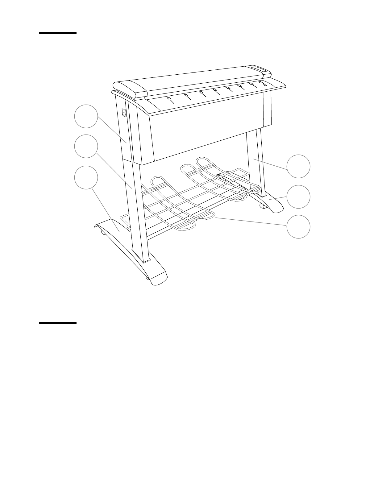
Meet your 4700 Series scanner
A
B
C
Océ Graphics
D
C
[1] Components
Delivery checklist
The 4700 Series scanner box con tains the following components:
■ 1 Scanner base
■ 2 Legs: left, right
■ 1 Scanner body
■ 1 Collection basket
■ 1 Power cable
■ 1 To ol bag: 4 short screws, 4 long screws, 1 Allen wrench
■ 1 Height alignm ent ch a rt
■ 1 Installation manual
E
A: Scanne r bo dy
B: Left leg
C: Scanne r ba se
D: Right leg
E: Collection basket
10 4700 Series Scanners Installation Manual
Page 11
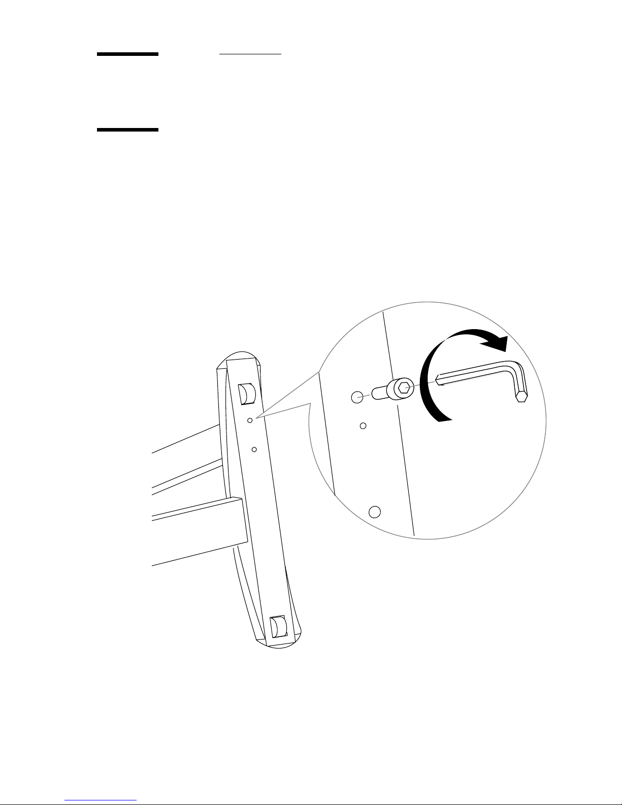
Assembling the 4700 Series scanner
Mounting the scanner base and legs
1 Lay the scanner base on its side and attach the right leg to the right hand side
of the base using 2 of the short screws and the Allen wrench provided, as
shown in Figure 2. The right leg has an extra bolt at the bottom to differentiate
it from the left leg. The black plastic hole on each leg should face the back .
2 Now attach the left leg using the remaining 2 short screws.
3 Stand the scanner base upright with the black plastic holes in the legs towards
the back.
[2] Attaching the leg to the base
Assembly and Installation 11
Page 12

Mounting the scanner body
1 Two people are needed to move the scanner body. Carefully place the scanner
body on top of the two legs with the insertion slot facing forward. Ensure that
the bolts on the top of each leg fit into the holes in the bottom of the scanner
body. See Figure 3 below.
[3] Mounting the scanner body
12 4700 Series Scanners Installation Manual
Page 13
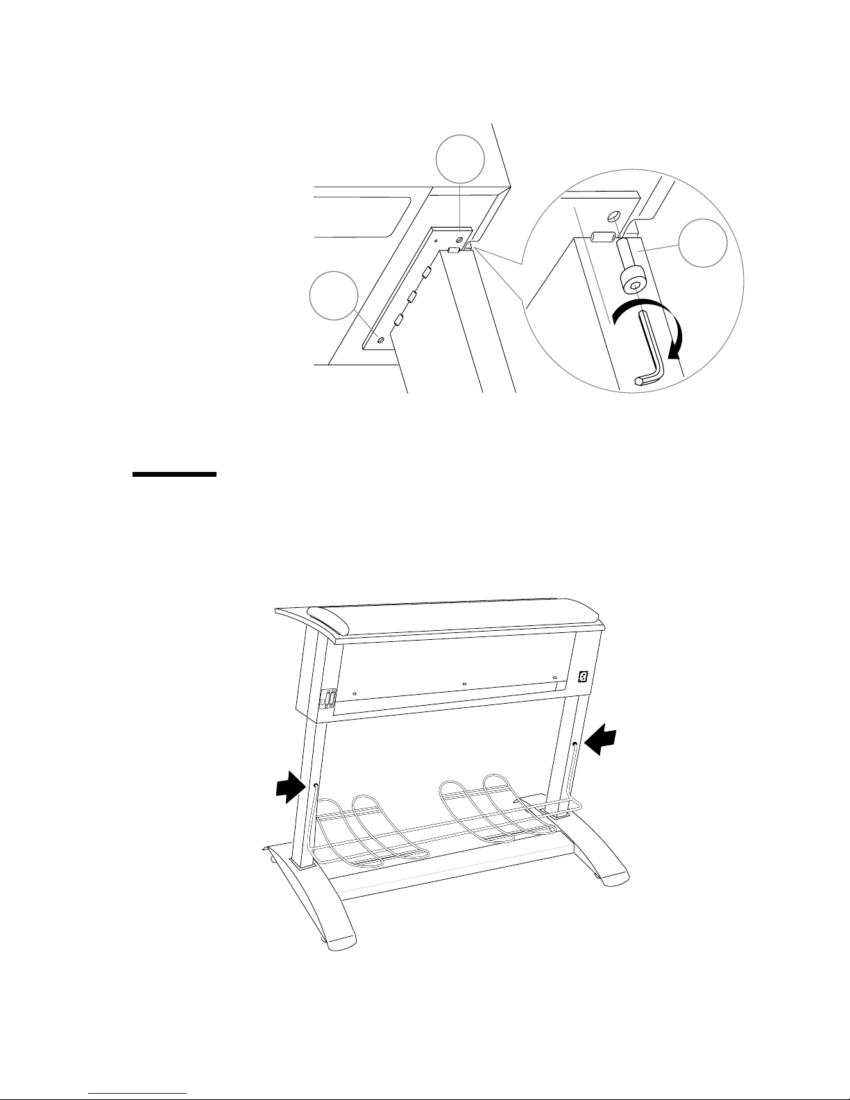
2 Now attach the scanner body to the legs using the 4 long screws (C) in the holes
(
A and B) on each side.
A
C
B
[4] Attaching the scanner body
Affixing the collection basket
To affix the basket onto the scanner, fit each end into the black plastic hole in
each leg as shown below.
[5] Affixing collection basket
Assembly and Installation 13
Page 14

Installing the 4700 Series scanners
Power supply
The 4700 Series scanner is earthed via a 3-wire power cable to a 2-pole and
earth power outlet with a maximum 16 amp protection.
Your electrical installation must comply to IEC 364 standards and with the of
national sta nda r ds of your country.
The scanner voltage is 100/120/220/240V, 60/50Hz, 80 VA.
The power supply is protected with one fuse for all voltages, type T2.5 AH
(5 x 20 mm).
‘.’ on page 14 .
Operating recommendations
■ In order to obtain the best results, use your scanner in an environment with a
temperature ranging from 59°F to 89°F (15°C to 32°C) and a relative
humidity lower than 80%.
■ If these conditions cannot be met, the installation of an air conditioning
system is recommended.
■ You should position the scanner a couple of centimeters away from the wall
so that the scanned originals can fall down freely and be easily recuperated
in the basket.
■ Ensure that enough air surrounds the scanner in order to avoid overheating.
14 4700 Series Scanners Installation Manual
Page 15
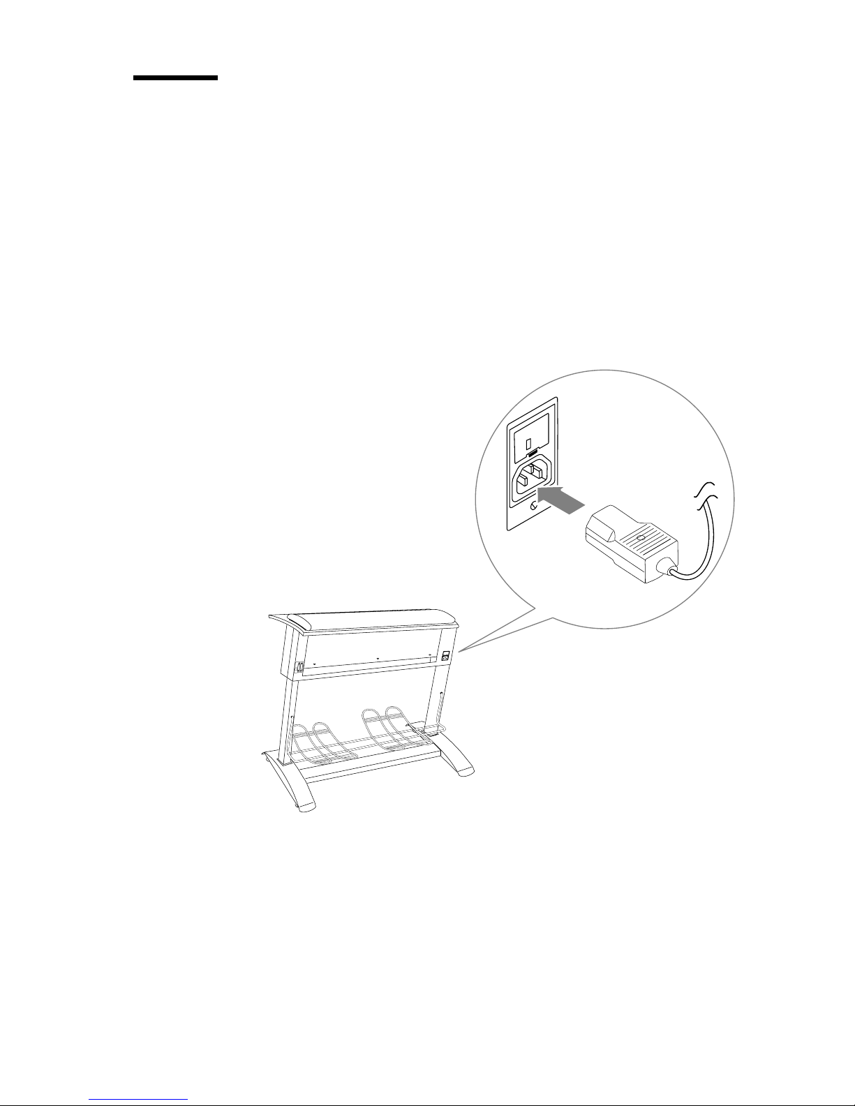
Switching the scanner on
Locate the power assembly at the back of your sca nn er:
1 Plug the power cable delivered with the scanner into the power socket.
2 Now plug in the other end of the cable into the mains.
3 Press the ON/OFF switch to ON.
The warm-up i ndicator on the scanner cont rol panel no w lights up and re mains
lit while the scanner carries out various internal diagnostic tests. When fully
powered on, the Power-on indicator is on continuously.
[6] Power supply
Assembly and Installation 15
Page 16

16 4700 Series Scanners Installation Manual
Page 17

4700 Series Scanners
Installation Man ual
Chapter 3
Operation and Upkeep
This chapt er desc ribes h ow to ope rate th e 4700 Se ries s canner. Befor e y ou
can actually begi n scann ing, yo u must in stal l the Pow er Sc an scan ning
software and the SCSI board, if applicable. Refer to the accompanying
manual, Power Scan User’s Manual for further details.
17
Page 18
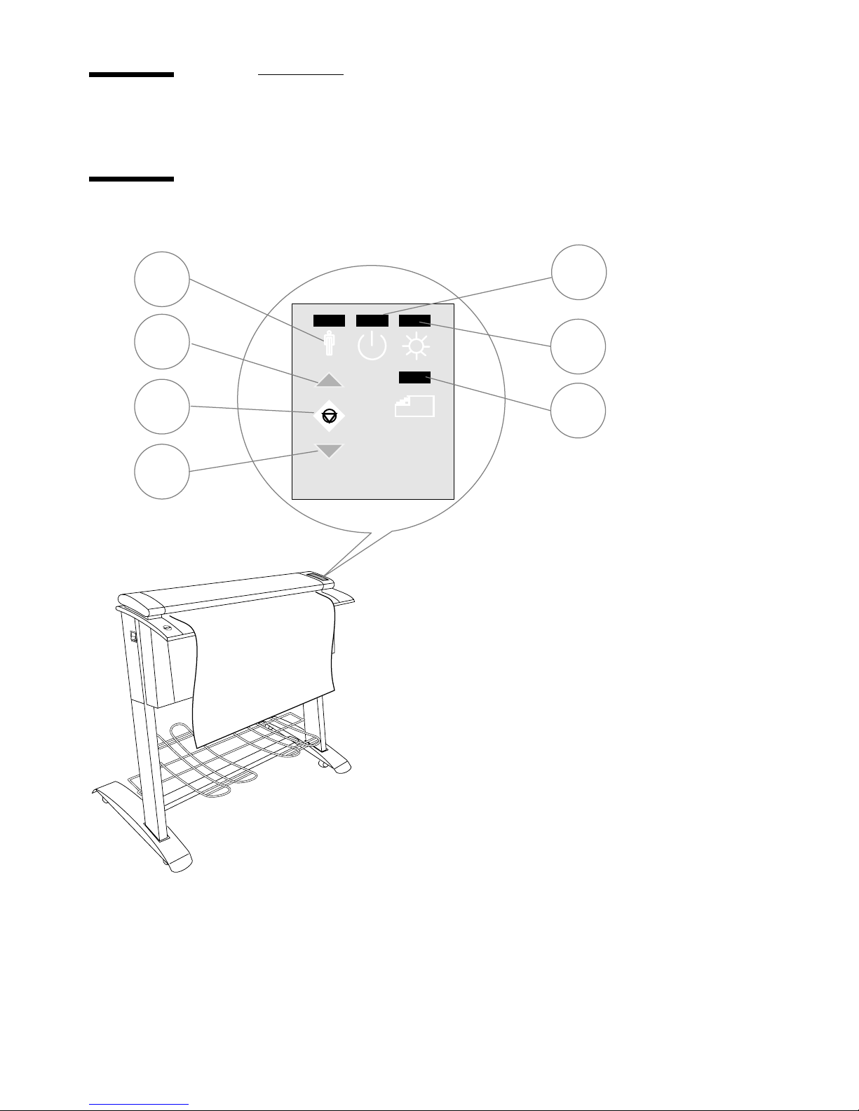
Scanning se t up
Using the control panel and inserting a document
A
D
F
G
B
C
E
Océ Graphics
G6035
A: Call service indicator
B: Warm-up indicator
C: Power on indicator
D: Paper feed key
E: Scan in progress
F: Abort scanning key
G: Paper revers e key
[7] Control panel
18 4700 Series Scanners Installation Manual
Page 19

Power On Indicator (Orange LED)
This indicator lights up when the scanner is turned on.
Warm-Up Indicator (Red LED)
When the scanner is powered up, the Warm-Up indicator lights
up for 1 minute during which internal diagnostic checks are
carried out. The scanner cannot be activated during this phase.
Paper Feed Key and Scan-in-Progress indicator
You can now place your document face down along the edge of
the document insertion slot.
The document insertion slot is marked with a ruler from 0 to 8.5.
The divisions correspond to the Scan width setup in the Power
Scan software. See figure 3.2 and refer to the tab l e on page 3-5.
Press the
position. The
Paper Feed key: the document moves up to the start
Scan-in-Progress (Green LED) indicator is now lit
continuously, i.e. the scanner is ready to receive instructions.
During scanning, the Scan-in-Progress indi cator blinks on and of f.
When scanning has finished, the Scan-in-Progress indicator is
continuously lit again. Press the Paper Feed key to eject the
document.
Pressing the Paper Feed key during scanning automatically stops
scanning and forwards the document through the scanner for as
long as you press key.
Note: If you remove the document from the scanner manually,
the Scan-in- Pr ogress Indicator stays on . Simply press the Paper
Feed key to reset it.
Paper Reverse key
When this key is pressed, scanning stops and the document is
reversed back through the scanner for as long as you press the
key.
Operation and Upkeep 19
Page 20
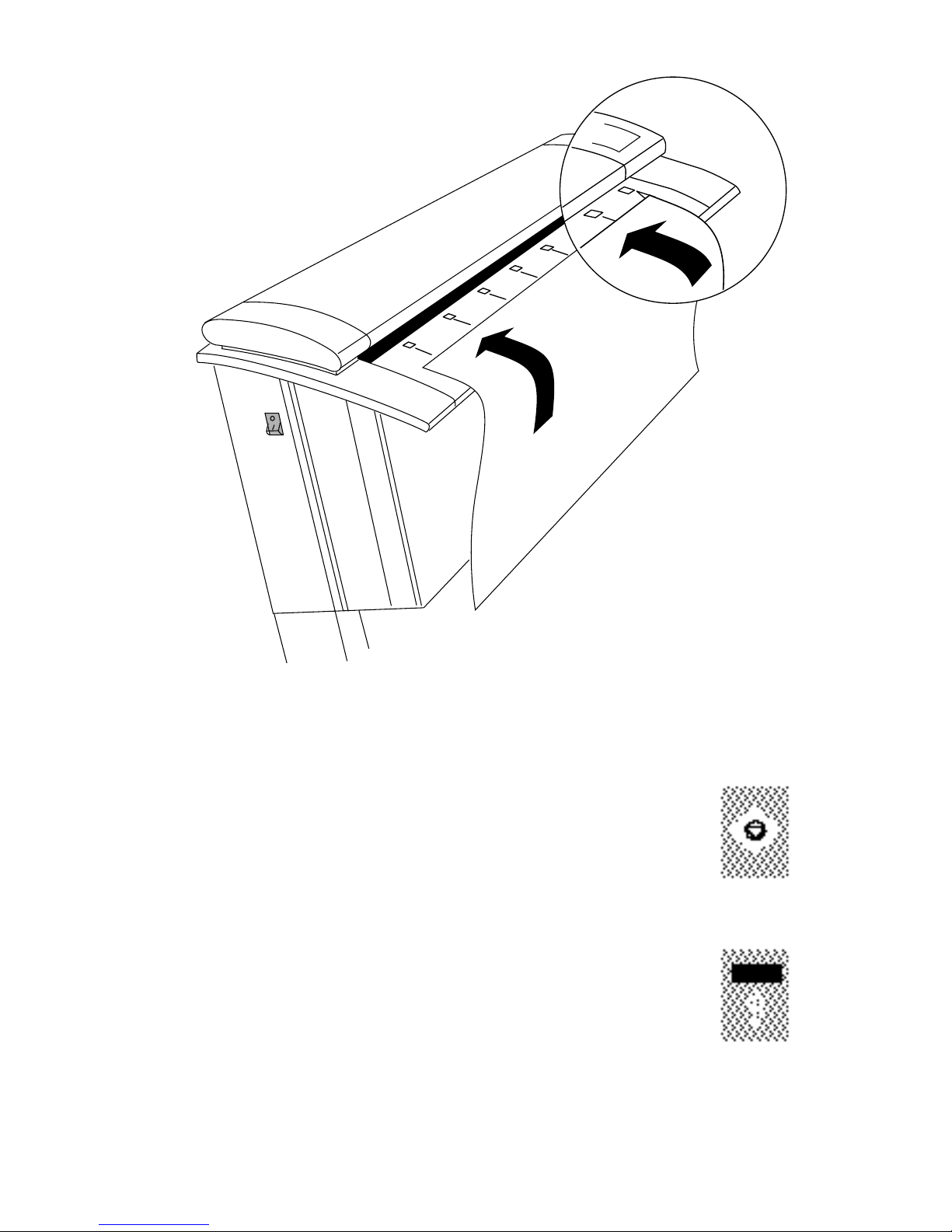
[8] Inserting a document
Abort Scanning key
You can cancel the scanning in process either from your computer software or by
pressing the Abort Scanning key. Note that once a scan has been canceled, it has to
be resumed from the b egi nning .
Call Service Indicator
This indicator flashes if the scanner detects a fatal error. Call
your local Océ service office to deal with the problem.
If the
Call Service and th e Warm-up indicators flash at the same
time, the amount of light captured by the scanner cameras is too
low. The camera height and range nee d to b e adjusted. Refer to
‘Camera out-of-light error’ on page 29 for instructions.
20 4700 Series Scanners Installation Manual
Page 21

Document insertion slot and ruler
The document insertion slot shown on the previous page is marked with a
measurement ruler fr om 0 t o 8.5. The divisions corres pond to the Sca n Width
settings in the Power Scan software.
The following table shows common ISO and ANSI document widths and their
required Scan width settings. Note that the minimum media size the scanner
can handle is 6.0 " (1 52 mm).
Scan-Width Document width
1.4 Minimum scan width (A5) 6.0" 152 mm
2. A-Size (letter) and approx. A4 8.5" 216 m m
2.6 B-Size (11") 11.0" 280 mm
2.8 A3 (297 mm) 11.9" 302 mm
3. Approx. A3 and ap prox. B-Size 12.7" 323 m m
3.9 A2 (420 mm) 16.5" 420 mm
4. C-S i ze and approx . A2 17.0" 430 mm
5.2 D-Size (22") 22.0" 560 mm
5.5 A1 (595 mm) 23.3" 592 mm
6. Approx. A1 and ap prox. D-Size 25.4" 646 mm
7.8 A0 (841 mm) 33.1" 840 mm
8. E-S i ze and approx. A0 34.0" 862 mm
8.5 Max. scan width 36.0" 914 mm
Max. media siz e handled 40.0" 1016 mm
The required setting for an original drawing can be measured on the printed
ruler when the document is placed in the insertion slot.
Operation and Upkeep 21
Page 22
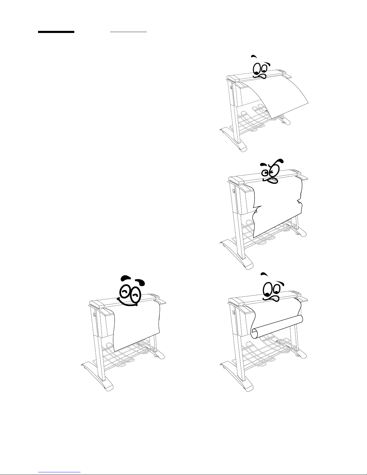
Precautions for use
The quality of the scanning operations
depends widely on the quality of the
original document yo u feed the scanner
with.
■ To avoid paper jams, do not feed the
scanner with very thin or thick
documents. If necessary, duplicate
your original document to provide
your scanner with the appropriate type
of media.
■ Do not scan a document that is
crumpled or has torn edges.
■ Flat original documents offer the best
operation. If you r dr awi n g ha s be en
rolled, do not use it immediately. Keep
it flat for several hour s prior to
scanning.
22 4700 Series Scanners Installation Manual
Page 23
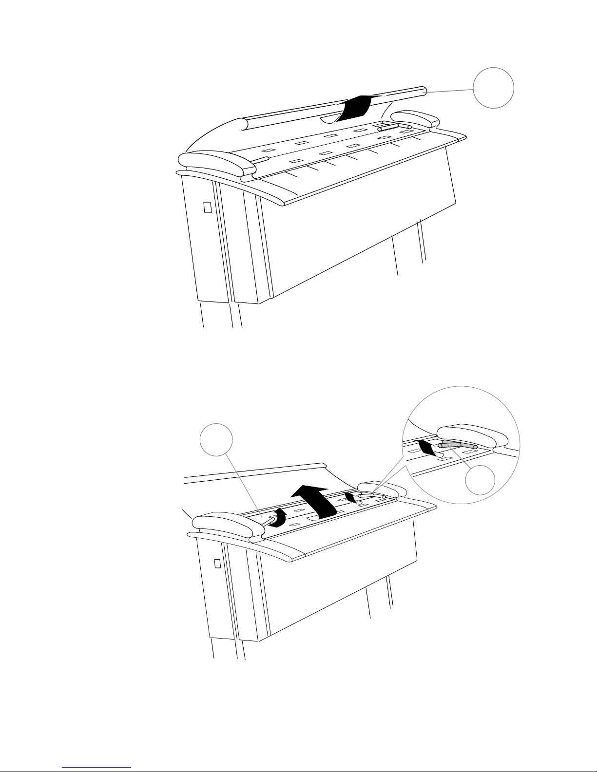
[9] Opening the Scanner
A
B
[10] Removing the Guide Plate
C
Operation and Upkeep 23
Page 24
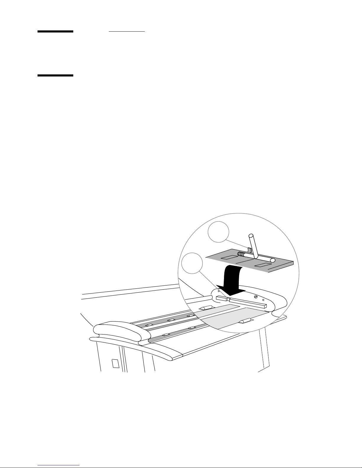
Maintenance
Cleaning the scanning area
Clean the scanning area from time to time to remove any residual paper dust.
1 Switch the power Off and disconnect the power cord. Gently open the top
cover (
2 Holding the handles (C) at each end of the guide plate (B) as shown in figure
10, lift the guide plate up and away from the scanner. Place the guide plate on
the top cover.
3 Carefully wipe clean the glass plate and the white area on the guide plate with
a cleaning solution suitable for comp uter peripherals.
4 Put the guide plate back in its operating position as shown in figure 11. Hold
the handles (
Lower the guide plate into position.
A) as shown in figure 9 on page 23.
C) up and position the vertical tabs (D) over the notches (E).
[11] Replacing the Guide Plate
D
E
24 4700 Series Scanners Installation Manual
Page 25
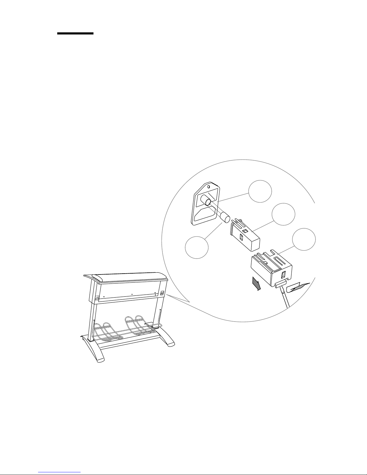
Changing the main power fuse
If you need to change the fuse:
1 Tu rn the scanner off and disconnect the power cable. Locate th e power
assembly (
2 Open the voltage box (B) by lifting the plastic tab with the tip of a screwdriver .
3 Remove the fuse block (C).
4 Change the blown fuse (D), type T 2.5 AH fuse for all voltages (5 x 20 mm).
5 Place the fuse block back in its original position and replace the voltage box
(The voltage displayed must correspond to your mains).
6 Reconnect the power cord to the scanner and switch the scanner on.
7 If the fuse blows again, call your local Océ service office.
A) at the back of the scanner.
A
C
[12] Changing the Fuse
B
D
Operation and Upkeep 25
Page 26
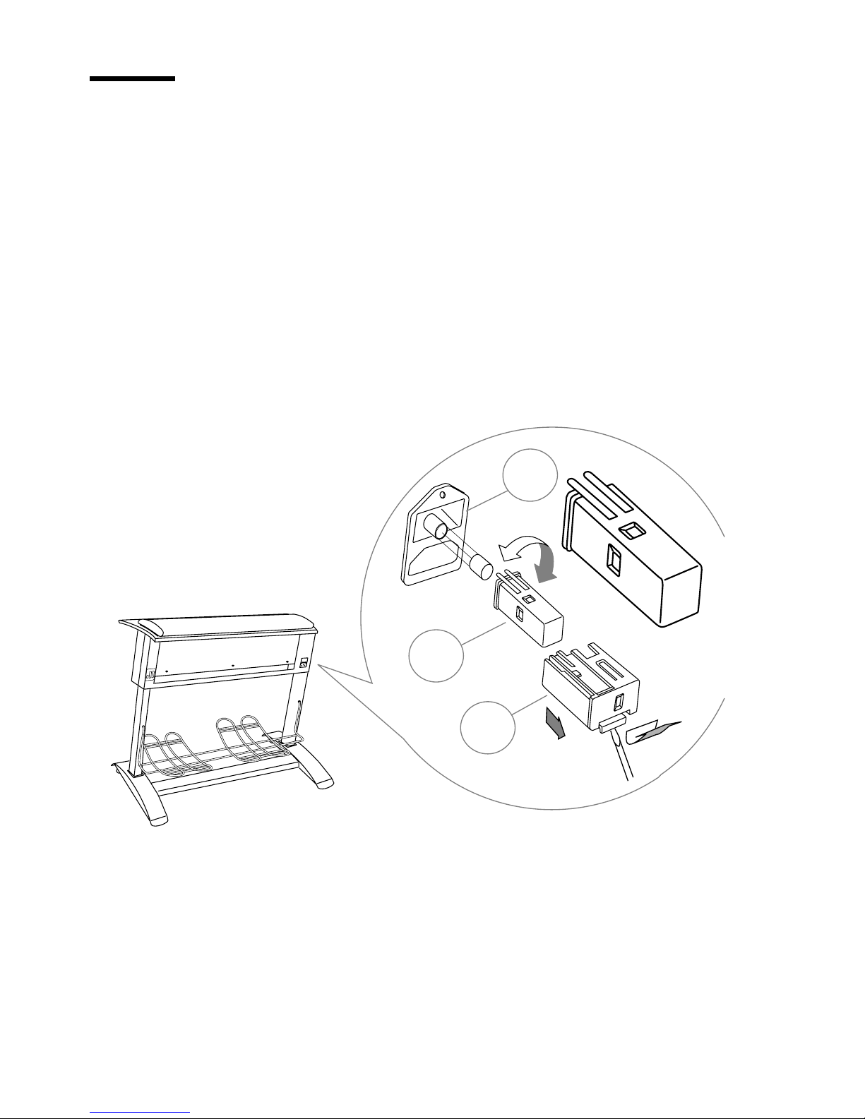
Changing the power voltage
Your scanner power voltage has been preset to meet the 220 V requirements.
To change it to fit other national standards, proceed as follows:
1 Turn the scanner off and disconnect the power cable. Locate the po wer
assembly (
2 Open the voltage box (B) by lifting the plastic tab with the tip of a screwdriver.
3 Remove the fuse block (C).
4 Rotate the fuse block 90°, 180° or 270° so that the appropriate voltage appears
in the voltage aperture.
5 Put the voltage box back into its orinal position, reconnect the power cord and
turn the scanner on.
A) at the back of the scanner.
A
[13] Changing the Power Voltage
C
B
240
100
220
120
240
100
220
120
26 4700 Series Scanners Installation Manual
Page 27
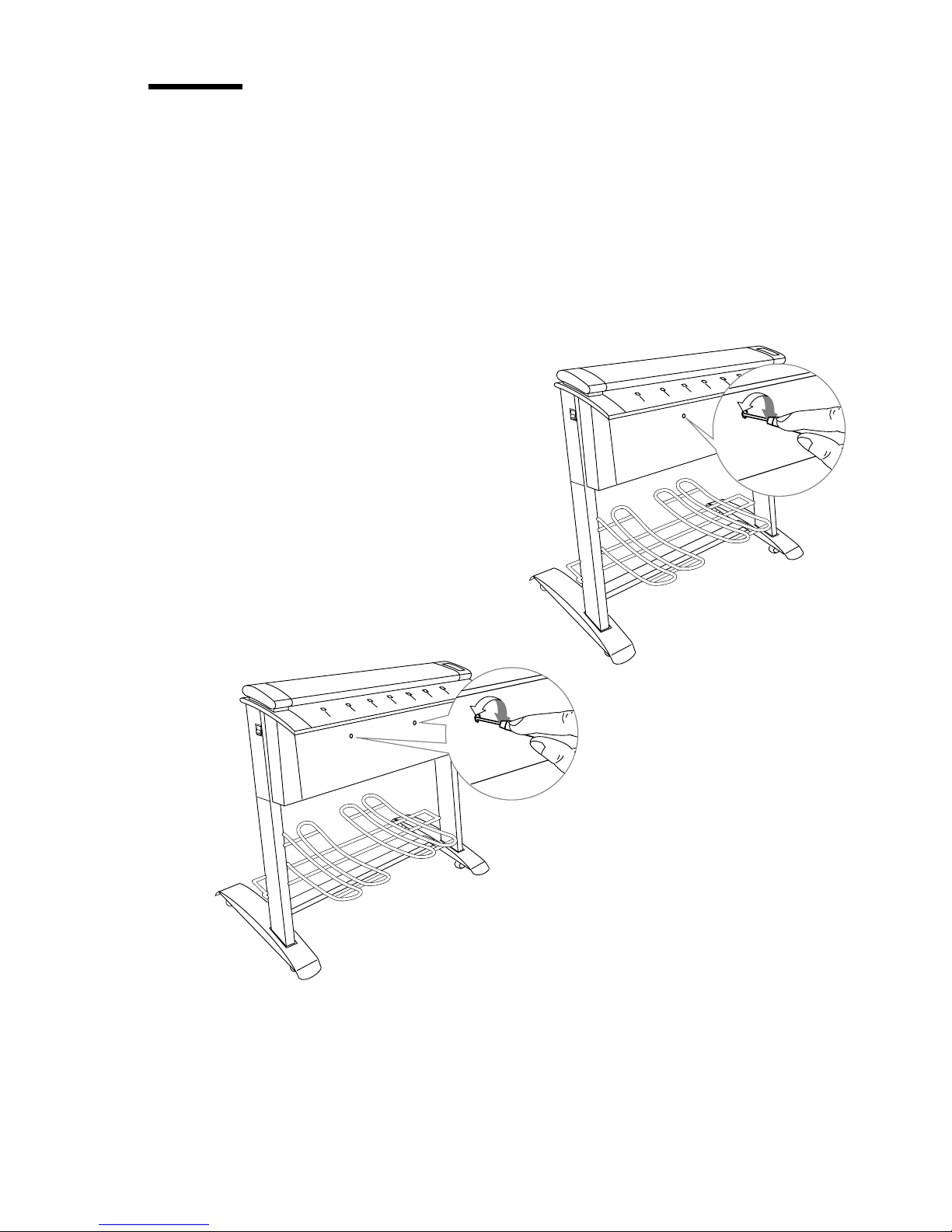
Adjusting the height of the cameras
Adjust the height of the cameras using the Power Scan software program and
the
Height Alignment Chart delivered with the scanner.
Note: This camera height adjustment does not apply to the 4715 scanner si nce
it is equipped with a single camera.
Only verify the camera height adjustment on repeated down-scans in ord er to
omit angle errors.
4740
[14] Adjusting Camera Alignment
4730
Operation and Upkeep 27
Page 28
4730 model
Insert the Height Alignment Chart into the scanner and press Paper Feed.
1
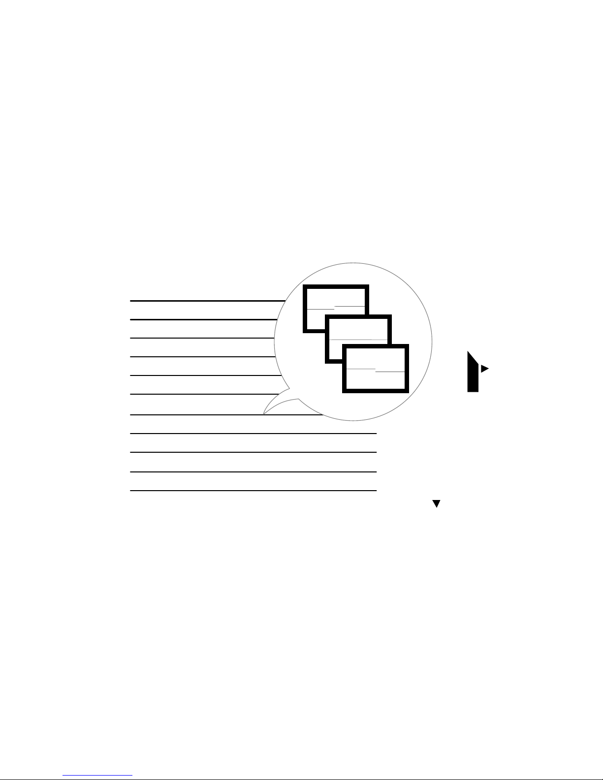
2 In Power Scan, select a Scan Width of 8.5 and press Forward to prescan.
3 When the horizontal lines have been prescanned press Halt.
4 Set the Detail window from the center of the Overview window so that you can
view the lines clearly.
The
Detail window should resemble one of the three as below.
5 Use a small screwdriver to turn the screw through the hole on the front of the
scanner body (see figure 14) either clockwise or anti-clockwise until the
horizontal line is a continuous line:
Clockwise: Line on the righ t side of the screen moves down.
Anti-clockwise: Line on the right side of the screen moves up.
HEIGHT ALIGNMENT CHART
PART NO. 6399A102
[15] Checking Camera Alignment
INSERT THIS EDGE AT
INSERT THE TEST CHART
WITH THIS SIDE DOWN
0 1 2 3 4 5 6 7 8 9 10 11 12 13 14 15 16 17 18 19 20 21 23 24 25 26 27 28 29 30 31 32 33 34 35 36 37 38
INSERT THIS EDGE
0
4740 model
To adjust the left camera (seen from front of scanner), follow same procedure
1
as for the 4730 model, but select a
from the left of the
Overview window. Use the screwdriver through the left
Detail window centered about one-third in
hole.
2 To adjust the right camera, follow the above procedure, but select a Detail
window centered about one-third in from the right of the
Overview window.
Use the screwdriver through the right hole.
28 4700 Series Scanners Installation Manual
Page 29

Camera out-of-light error
If the Call Service and Warm-Up indicators start blinking together on the
scanner Control Panel, one of the cam eras has moved out of range during
adjustment or transport and then it does not receive enough light.
The Warm-up indicator shows by the number of flashes per second which
camera is out of light:
Camera 1 1 flash per second
Camera 2 2 flashes per second
Camera 3 3 flashes per second
Before adjusting the camera height, carry out the following procedure:
1 Turn the height adjustment complete anti-clockwise.
2 Turn the height adjustment one quarter of a turn clockwise.
3 Turn the scanner power off and then on. If the error still occurs repeat steps 2
and 3.
After clearing the "Camera out of light error", proceed with the Camera height
adjustment described previousl y.
Operation and Upkeep 29
Page 30

30 4700 Series Scanners Installation Manual
Page 31

4700 Series Scanners
Installation Man ual
Appendix A
Technical References
31
Page 32

4700 Series scanner specifications
Sensors 4715: Single CCD 8,000 pixels
4730: Dual CCD 16,000 pixels
4740: Triple CCD 24,00 0 pixels
Optics Apochromatic lenses, compact folded path torsion
stabilized for portability
Camera Equalizations Automatically calibrated at each scan
Light Source Stabilized fluorescent lamp
Resolution (dpi) 4715: 400, 300, 200, 150, 100, 75, 25
4730: 800, 600, 500, 400, 300, 200, 150, 100 , 75, 25
4740: 1200, 1000, 800, 600, 500, 400, 300, 200, 150 , 100, 75, 25
Accuracy: 0.15% (0.1% over scan width) at 64° F to 75° F
(18° C to 24° C)
Media Width 5.98" to 40 " (152 mm to 1016 mm)
Scan Width 36" (914 mm)
Scan Length Unlimited by the scanner
Line Detectability 4715: 76 lpi (3.0 l/mm)
4730: 11 4 l pi (4.5 l/mm)
4740: 170 lpi (6.7 l/m m)
Gray Levels 256 levels recognized (8 bits per pixel)
Interface SCSI, standard 50 pin connector
Dimensions 48.35" x 24.8" x 39.75" (1228 x 630 x 1010 mm)
Weight (with pedestal) 165.35 pounds (75 kg)
Power Supply 100-240 V, 60-50 Hz, 80 VA
Media Types Plain paper, tracing paper
Operating Temperature 59° F to 89° F (15°C to 32°C)
and Humidity up to 80%, non-condensing
Storage Temperature 14°F to 158°F (-10°C to 70°C)
and Humidity up to 80%, non-condensing
Safety & Environmental
Requirements
Sound Level standby < 25 dBA, operating 45 dBA
CE Mark
32 4700 Series Scanners Installation Manual
Page 33

4700 Series scanner connectivity kits
Each of the following Connectivity Kits corresponds to a specific workstation.
All kits include the 4700 Series Power Scan Scanning Software User’ s Manual.
Whenever you intend to connect your scanner to a new workstation type,
contact our Océ representative. The following kits are available:
4700 Series and P C/AT computer ( D O S/Windows 3.1,
DOS/Windows 95, DOS/Windows-NT)
4700 Series and Sun workstation/Solaris 2
4700 Series and HP workstation
4700 Series and IBM RS/6000 workstation
4700 Series and Silicon Graphics workstation
Technical References 33
Page 34

34 4700 Series Scanners Installation Manual
Page 35

Appendix B
Miscellaneous
4700 Series Scanners
Installation Man ual
35
Page 36

Notation conventions
There are a number of notation conventions used in this manual. This
consistent style enables you to quickly become conversant with the use of this
manual and consequently the 4700 Series Scanners.
Description Each section or subsection contains a description of the feature or
operation identified in the title. It might also include possible applications, as
well as any guidelines that you should bear in mind.
Procedures A description is followed by a procedure. A procedure always
begins with a phrase which briefly describes the procedure (for example,
Loading paper:) followed by a series of numbered steps that take you, step by
step, through all phases of performing the operation.
Figures and tables Figures and tables are titled and numbered sequentially
throughout this manual. Figures include pictures of product components,
examples, and diagrams of con cepts discussed in the description.
Attention getters There are several types of information to which we draw
your attention. This information is classified as follows:
Note: In a ‘Note’, information is given about matters which ensure the proper
functioni ng of t he dev ice , but usefu l advic e con ce rnin g its op erat ion m ay al so
be given.
Attention: The information that follows ‘Attention’ is given to prevent
something (your original, the equipment, etc.) being da mag ed.
Caution: The inform ation tha t follow s ‘Caut ion’ is gi ven to prevent you
suffering personal inj ury.
36 4700 Series Scanners Installation Manual
Page 37

Reader’s comment sheet
Have you found this manual to be accurate?
❏ Yes
❏ No
Could you opera t e th e product after reading this manua l?
❏ Yes
❏ No
Does this manual provide enough background informati on?
❏ Yes
❏ No
Is the format of this manual convenient in size, readability and arrangement
(page layout, chapter order, etc.)?
❏ Yes
❏ No
Could you find the information you were looking for?
❏ Always
❏ Most of the times
❏ Sometimes
❏ Not at all
What did you use to find the required information?
❏ Table of contents
❏ Index
Are you satisfied with this manual?
❏ Yes
❏ No
Thank you for evaluating this manual.
If you have other comments or concerns, please explain or suggest
improvements overleaf or on a separate sheet.
Miscellaneous 37
403221246
Page 38

Comments:
--------------------------------------------------------------------------------------------
--------------------------------------------------------------------------------------------
--------------------------------------------------------------------------------------------
--------------------------------------------------------------------------------------------
--------------------------------------------------------------------------------------------
--------------------------------------------------------------------------------------------
Date:
This reader’ s comment sheet is completed by:
(Please fill in your occupation, even if you wish to remain anonymous.)
Name:
Occupation:
Company:
Phone:
Address:
City:
Country:
Please return this sheet to:
Océ-Nederland B.V.
For the attention of ITC user documentation.
P.O. Box 101,
5900 MA Venlo
The Netherlands
38 4700 Series Scanners Installation Manual
Page 39

Your Océ contacts
AUSTRALIA
Océ Australia Ltd.
89 Tulip Road
Cheltenham VIC 3192
Tel: (61-3) 263 33 33
Fax: (61-3) 584 43 57
AUSTRIA
Océ-Osterreich GmbH
Carlbergergasse 38
A-1230 Wien
Tel: (43-1) 865 36 10
Fax: (43-1) 865 33 27
BELGIUM
Océ Belgium S.A./N.V.
Avenue Jules Bordet, 32
1140 Brussels
Tel: (32-2) 729 48 11
Fax: (32-2) 729 49 10
BRAZIL
Océ Brasil
Av. Candido Portinari, 1174
05114 Sao Paulo SP
Tel: (55-11) 261 64 66
Fax: (55-11) 832 25 88
CZECHOSLOVAKIA
Océ Ceska republika s.r.o.
K Rysance 16
147 54 Praha 4
Tel: (42-2) 463 451
Fax: (42-2) 461 260
DENMARK
Océ Danmark A/S
Kornmarksvej 6
DK 2605 Broendby
Tel: (45-43) 63 00 22
Fax: (45-43) 43 06 22
FRANCE
Océ-France S.A.
32, avenue du Pavé Neuf
B.P. 2
93161 Noisy le Grand
Tel: (33-1) 45 92 50 00
Fax: (33-1) 43 05 12 15
GERMANY
Océ-Deutschland GmbH
Solinger Straße 5-7
45481 Mülheim a. d. Ruhr
Tel: (49-208) 48 45 0
Fax: (49-208) 460 167
HONG KONG
Océ (Hong Kong) Ltd.
No 1, Hysan Avenue
Causeway Bay, Hong Kong
Tel: (852) 577 60 64
Fax: (852) 577 89 57
HUNGARY
Océ Hungaria KFT
Karpat Ut 42
1133 Budapest
Tel: (36) 1 269 8836/8837
Fax: (36) 1 269 8835
ITALY
Océ Italia S.p.A.
Via Cassanese, 206
20090 Segrate, Milano
Tel: (39-2) 21 63 1
Fax: (39-2) 21 63 398
MALAYSIA
Océ Systems Sdn. Bhd.
15A, Jalan Universiti,
46200 Petaling Jaya,
Selangor Darul Ehsan,
Tel: (603) 7584088
Fax: (603) 7556125
NETHERLANDS
Océ Nederlandse
Verkoopmaatschappij B.V.
Brabantlaan, 2
5216 TV Den Bosch
Tel: (31-73) 68 15 815
Fax: (31-73) 61 20 685
NORWAY
Océ Norge A.S.
Gjerdrums vei 8
0486 Oslo 4
Tel: (47-22) 95 05 20
Fax: (47-22) 95 05 30
POLAND
Océ-Poland Ltd.
02-0232 Warszawa
ul. Lopuszanska 53
Tel: (48-22) 467429
Fax: (48-22) 467431
Miscellaneous 39
Page 40

PORTUGAL
Océ-Lima Mayer S.A.
Av. Infante D. Henrique
Lote 309
1900 Lisboa
Tel: (351-1) 859 40 71
Fax: (351-1) 859 48 28
SINGAPORE
Océ (Singapore) Pte Ltd
1 Clementi Loop #01-01/02
Margateo Districentre
Clementi West Distripark
Singapore 129808
Tel: (65) 467 38 66
Fax: (65) 466 67 29
Océ (Far East) Pte Ltd
1 Clementi Loop #02-10
Margateo Districentre
Clementi West Distripark
Singapore 129808
Tel: (65) 467 30 22
Fax: (65) 466 74 26
SWITZERLAND
Messerli
Sägereistrasse 29
P.O. box 114
8152 Glattbrugg ZH
Tel: (41-1) 829 11 11
Fax: (41-1) 829 13 48
TAIWAN
Océ Graphics (Taiwan) Ltd
No 99-24, Nan-Kang Road,
Sec 2
Taipei, Taiwan, R.O.C.
Tel: (886-2) 651 65 16
Fax: (886-2) 783 32 42
THAILAND
Océ (Thailand) Ltd
B.B. Building, 16th Floor
54 Asoke Road
Sukhumirt 21
Bangkok 10110
Tel: (662) 260 71 33
Fax: (662) 260 71 37
USA
Océ-Bruning Inc.
1800 Bruning Drive West
Itasca, IL 60143
Tel: (1-708) 351-29 00
Fax: (1-708) 351-75 49
AFRICA,
MIDDLE-EAST,
SOUTH AMERICA,
EASTERN EUROPE
Océ-Nederland B.V.
Direct Export
P.O .Box 101
5900 MA
Venlo
The Netherlands
Tel: (31-77) 359 39 00
Fax: (31-77) 359 54 31
SPAIN
Océ España S.A.
Poligono Mas Blau
c/Osona, 2
08820 Prat de Llobregat
Tel: (34-3) 484 48 00
Fax: (34-3) 484 48 28
SWEDEN
Océ Svenska A.S.
Isafjordsgatan 5
Box 1231
164 28 Kista
Tel: (46-8) 703 41 50
Fax: (46-8) 703 99 86
UNITED KINGDOM and
IRELAND
Océ-Engineering Systems
(UK) Ltd
300 Park Avenue
Aztec West, Almondsbury
Bristol, BS12 4RG
Tel: (44-1454) 61 77 77
Fax: (44-1454) 61 84 35
Océ (UK) Ltd
Langston Road
Loughton
Essex, IG 103SL
Tel: (44-181) 508 55 44
Fax: (44-181) 508 66 89
40 4700 Series Scanners Installation Manual
Page 41

Index
A
Abort Scanning key 20
Accuracy 32
Addresses (Océ offices worldwide) 39
Adjusting the camera heigh t 26
Alignment Ch ar t 28
ANSI 21
C
Call Service i ndi cator 20
Camera height (Adjust in g) 27
Collection basket (Affixing) 13
Connectivity Kits 33
Control Panel
Illustration 18
Using 18
D
Delivery checklist 10
Document
Inserting 20
Widths 21
DOS (Connectivity kit) 33
H
HP workstation (Connectivity kit) 33
Humidity 14, 32
I
IBM RS/6000 workstation
Connectivi ty kit 33
Indicators (Cont rol panel) 18
Inserting a docum ent 20
Insertion slot 21
Installing (Scanning software) 6
ISO 21
M
Maintenance 24
Media
Minimum size 21
Precautions 22
Sizes 21
Type 22
Media Width (Max and Min) 32
F
Fuse changing 25
G
Gray Levels 32
Guide Plate Removing 24
Index 41
O
Océ offices 39
P
Paper Feed key 19
Paper Reverse key 19
Power
Cable 15
Fuse 25
Power On indicator 19
Power supply 14, 32
Page 42

R
Resolution 32
Ruler 21
S
Scan Width 32
Settings 21
Scan-in-Progress indicator 19
Scanner
Cleaning 24
Connecting to computer 6
Dimensions 32
Mounting 11
Operating advice 14
Specifications 32
Switching on 15
Scanning
Process 19
Quality 22
Scanning area (Cleanin g) 24
Scanning software
Installing 6
SCSI board
Installing 6
Silicon Graphi cs station (Connectivity kit) 33
Sun workstation (Connectivity kit) 33
T
Temperature 14, 32
W
Warm-Up 29
W a rm-Up indicator 19
Weight 32
Windows (Connectivity kit) 33
42 4700 Series Scanners Installation Manual42 4700 Series Scanners Installation Manual
 Loading...