

Page 1
Océ 3000
User Manual
Page 2

Océ-Technologies B.V.
This manual contains a description of the Océ 3000 and the microfilm scanning
that can be done with it. The introduction (chapter 1) contains a general
description of the working methods for using the microfilm scanner and it is
recommended that you read at least this chapter.
This manual reflects the following software:
Océ 3000 Windows apllication software version 4.1
Overview of scannerparts on the covers
To assist you in finding parts of the scanner quickly, an illustration of the
Océ 3000 microfilm scanner is presented on the inside back cover.
Safety information
This manual contains the following safety information:
■ Appendix B lists ‘Instructions for safe use’. You are advised to read this
information before you start to actually use the scanner. Technical safety
information such as safety data sheets can also be found in appendix B.
■ Where applicable, cautions and warnings are used throughout this manual to
draw your attention to safety precautions to be taken.
Copyright
Océ-Technologies B.V. Venlo, The Netherlands © 1997
All rights reserved. No part of this work may be reproduced, copied, adapted,
or transmitted in any form or by any means without written permission from
Océ.
Océ-Technologies B.V. makes no representation or warranties with respect to
the contents hereof and specifically disclaims any implied warranties of
merchantability or fitness for any particular purpose.
Further, Océ-T echnologiesB.V. reserves the right to revise this publication and
to make changes from time to time in the content hereof without obligation to
notify any person of such revision or changes.
Code number 0101953
Edition 4.0
GB
Page 3

Contents
Chapter 1
Introduction
The Océ 3000 Microfilm Scanner 8
General operation 9
Modes of working 10
Chapter 2
System installation
System requirements 12
Minimum PC requirements 12
Software installation 13
Preparing the PC for printing 13
Selecting a language 14
Start/ stop the scanning procedure 15
Chapter 3
Scanning
Loading cards 18
The Control window 19
The option bar 19
The selection buttons 20
The Control window 21
Scanning in Single mode 23
Cards with unknown Hollerith codes 23
Settings in the Control window 23
Scanning in Batch mode 25
Quality mode 25
Settings in the Control window 26
Scanning in Auto Feed mode 27
Cards without Hollerith punches 27
Settings in the Control window 27
Scanning in Hollerith Check mode 29
Settings in the Control window 29
The Run-Time Display window 30
Choosing a display mode 34
Full Image 34
Contents 3
Page 4

Chapter 4
Chapter 5
Enlarged 35
Dual 36
Zoom 37
The Viewing mode
Viewing image files 40
The view screen 41
Setting up the Océ 3000 Microfilm Scanner
The scanner setup 44
Imaging 45
Drawing Size 47
General Hollerith information 53
Hollerith Control 56
Predefined File Name 67
Automatic Card Selection 69
The printer setup 71
Print sequence 72
RCF file 72
Settings in the Print Control window 73
Configuration 85
Chapter 6
File handling and administration
The file handling setup 88
Scan data path 88
Process queue path 88
File format 89
Data Type 89
Save Option 90
The Job Management Menu 91
Maximum File Size 91
Log File Usage 92
Log file and Reject File 92
Additional functions 93
4 Océ 3000 User Manual
Page 5

Chapter 7
Appendix A
Appendix B
Maintenance and troubleshooting
Card jams 96
Cleaning the drum 98
Technical specifications
Technical specifications 100
Error messages 101
Safety information
Instructions for safe use 106
Safety data sheets 108
Safety data sheet Océ 3000 109
Appendix C
Appendix D
Defining User Defined file format
User Defined file format 112
Header Definition file 112
Header Template file 114
Checking the user defined file format 115
Miscellaneous
Notation conventions 118
Reader’s comment sheet 119
Index 121
Contents 5
Page 6

6 Océ 3000 User Manual
Page 7

Chapter 1
Introduction
Océ 3000
User Manual
This chapter contains a general description of the
Océ 3000 Microfilm Scanner.
7
Page 8

The Océ 3000 Microfilm Scanner
The Océ 3000 Microfilm Scanner is a table-top machine which is controlled
by the Océ 3000 Windows application software running in the controlling PC.
The figures on the inside of the cover of this manual show the main external
features of the scanner.
8 Océ 3000 User Manual
Page 9
General operation
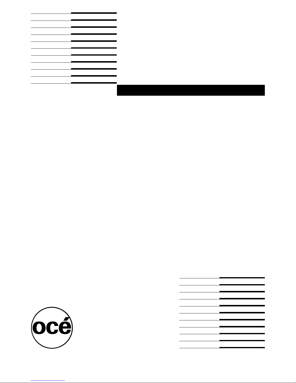
A complete scanning and printing system comprises the Océ 3000 Microfilm
Scanner, the controlling PC with the Océ 3000 Windows application software
and an Océ digital printer. The figure below shows an overview of the whole
system.
1220.eps
Ø2"
Ø2"
434.2
Ø2" Ø2"
CROSSMAIN EL. 7500
18.5
SPRINKLER EL. 7150
SPRINKLER
2256
Ø2"
Ø2"
BRANCHLINE EL. 7940
[1] Scanning, printing and filing
The cards to be scanned are placed in the input hopper of the scanner (1). You
start the scanning in the Control window of the Océ 3000 Windows application
software (2). The scanner then scans one card or a batch of cards (3). The
images are displayed on the screen of the controlling PC as the cards are
scanned. The controlling software provides a ‘zoom and pan’ facility to inspect
the produced images carefully.
According to the control settings in the software (4), the Océ 3000 Microfilm
Scanner allows you to produce prints of the scanned images using a digital
printer (5). You can also produce data files of the scanned images to store into
an image data directory. You can store the data files in the controlling PC, or
link the PC to a network, so that image data files can be sent to and stored in
any node of the network (6). All necessary controls for the scanning process
are available in menus in the controlling PC.
Introduction 9
Page 10

The special V iewing mode allows you to display a scanned image data file that
is stored in an image data directory . The ‘zoom and pan’ facility is available to
check all details of the data file.
The configuration of the scanner and printer and the handling of files is
controlled in various control menus.
The on-line help gives information on all aspects of the system operation.
Modes of working
The system may be operated in the following modes:
■ BATCH mode, which allows a batch of cards to be fed and scanned
automatically without your intervention.
■ SINGLE mode, which allows you to feed one card, inspect the image and if
necessary re-scan the card after settings are changed. Use this mode for
difficult microfilms or for setting up the scanning parameters before
automatic scanning of a series of cards in
■ AUTO FEED mode. After a single card is fed and scanned as in SINGLE mode,
the next card is automatically fed after pressing the Continue button. Use this
mode for small numbers of cards that need special attention.
■ HOLLERITH CHECK mode, which allows you to display and edit the Hollerith
data on the scanned card.
BATCH mode.
The system provides four different output modes:
■ PRINT mode, which allows you to make one or more prints of the scanned
images on paper.
■ FILE mode, which allows you to store the image data files into a specified data
directory .
■ PRINT/FILE mode, which is a combination of the two modes above. One or
more paper copies and a data file are made.
■ VIEW mode, which allows you to simply check the images on the screen of
the controlling PC without making paper copies or storing data files.
For more detailed information on how to run a scanning session in the various
modes see ‘Scanning’ on page 17.
10 Océ 3000 User Manual
Page 11

Chapter 2
System installation
Océ 3000
User Manual
This chapter informs you how to install the Océ 3000
Microfilm Scanner and the Océ 3000 Windows application
software.
11
Page 12

System requirements
This section describes the hardware and software requirements for running the
Océ 3000 V4.1 Windows application software.
Minimum PC requirements
Windows NT environment The Océ 3000 System Controller must conform to
the following minimum specifications:
■ minimal 486 DX with 100MHz clock frequency
■ I/O Expansion Bus with one free PCI slot
■ I/O ISA Expansion Bus clock speed of 8MHz (maximum)
■ minimal 32MB RAM
■ 100 MB Hard Disk
■ colour SVGA Monitor and Controller (minimum Resolution 800 x 600)
■ display adaptor must be set to 256 colours
■ Windows NT 3.51 or Windows NT 4.0
■ CD ROM drive
■ a Windows mouse.
Windows 95 environment The Océ 3000 System Controller must conform to
the following minimum specifications:
■ minimal 486 DX2 with 50MHz clock frequency
■ I/O Expansion Bus with one free PCI slot
■ I/O ISA Expansion Bus clock speed of 8MHz (maximum)
■ minimal 32MB RAM
■ 100 MB Hard Disk
■ colour SVGA Monitor and Controller (minimum Resolution 800 x 600)
■ display adaptor must be set to 256 colours
■ Windows 95
■ CD ROM drive
■ a Windows mouse.
12 Océ 3000 User Manual
Page 13

Software installation
The Océ 3000 Window application software is contained on one CD ROM.
The setup program performs the installation process automatically and sets all
configuration parameters to their required values.
Note: If you are using Windows NT, you must be logged in as
ADMINISTRATOR before starting the installation procedure.
▼ To install the Océ 3000 software:
Insert the Océ 3000 installation CD ROM in the disk drive of the PC.
1
2 Run ‘setup.exe’ from the CD ROM.
3 Now follow the instructions on the screen.
Preparing the PC for printing
▼ Preparing the PC for printing:
Open the Control Panel menu in Windows.
1
2 Select the Printers icon.
3 Add a Generic Printer (T ext only) and assign the appropriate address (local on
LPT1, 2, etc. or Network address).
4 Specify the printer name: ‘Centronics Printer’.
Note: This name is case sensitive, and the space is required.
5 Do not send a test page to the printer.
System installation 13
Page 14
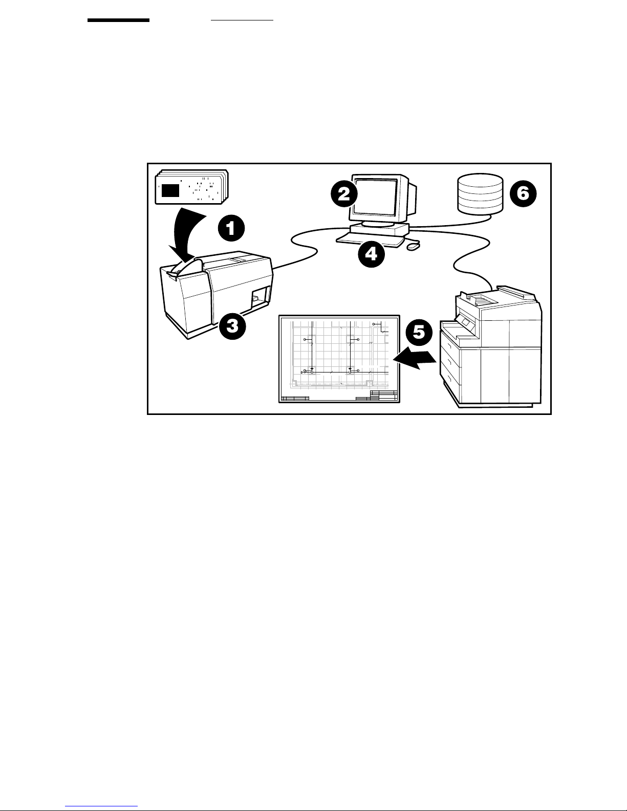
Selecting a language
You can specify the language in which the Océ 3000 Windows software is
displayed on your screen. You can choose English, French, German or Italian.
▼ To select a language:
Open the Control Panel menu in Windows.
1
2 Select Regional Settings.
3 Specify the desired language in the Language selection box.
Note: If you choose a language that is not supported, English will be
selected as default language.
2065.tif
[2] Language selection
4 Click OK to go back to the Control Panel window.
5 Exit the Control Panel window.
You can now start the Océ 3000 Microfilm scanner Windows application.
14 Océ 3000 User Manual
Page 15
Start/ stop the scanning procedure
This section explains the procedure for start and stop the scanning, including
switching on/off the scanner and the PC.
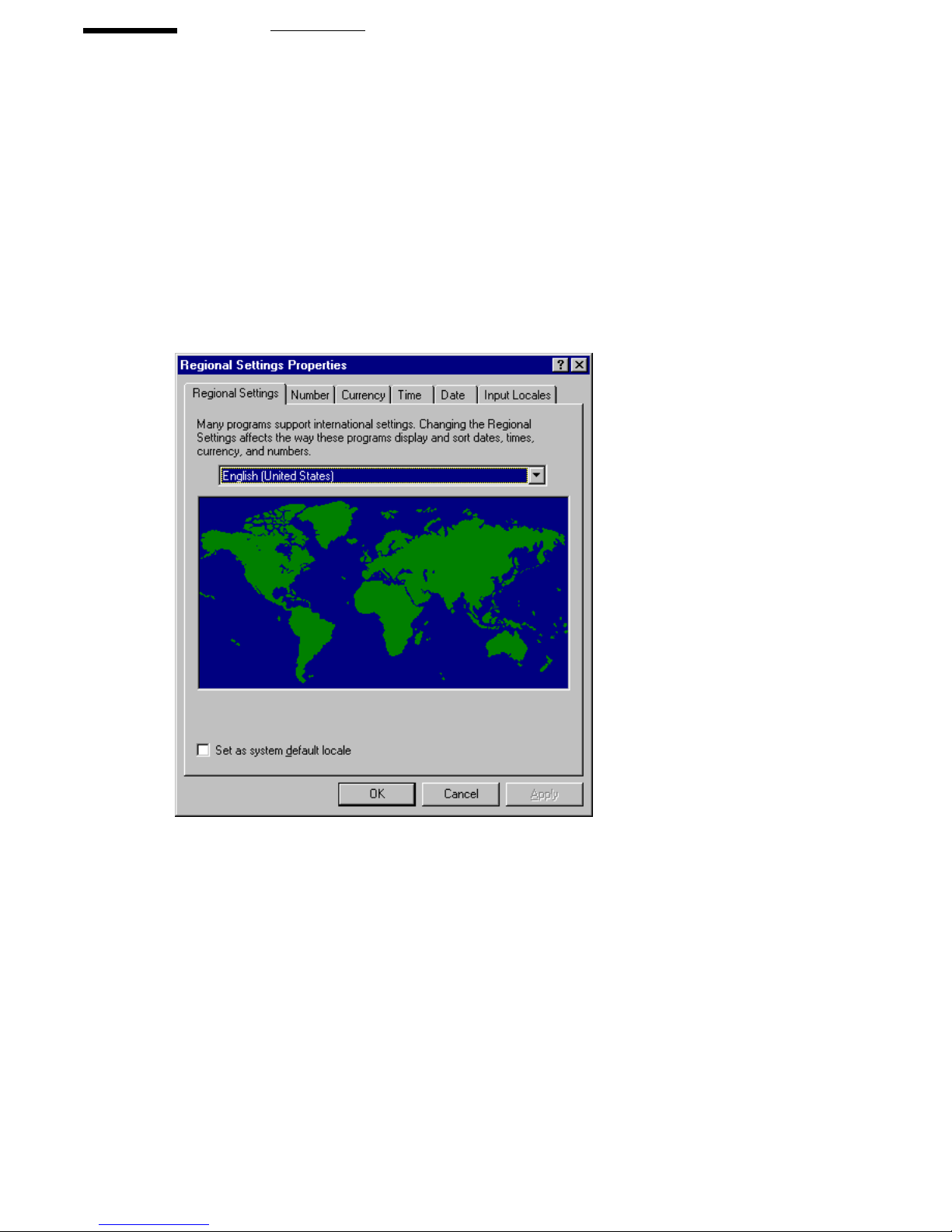
▼ To switch the scanner on:
Switch the ON/OFF switch on the rear of the Océ 3000 Microfilm Scanner to
1
the ‘I’ (
ON) position (see figure 3 ).
1227.eps
2244
[3] The ON/OFF switch
▼ To start the window application:
Switch the controlling PC on.
1
2 Start Windows.
3 With Windows running, open the Océ 3000 Scanner Group.
4 Double click the Océ 3000 icon.
The system starts up and performs a self-test. When the calibrating procedure
is finished (after about 30 seconds), the Control screen is displayed.
If the system is not to be used for several hours, switch the scanner system off.
▼ To stop the windows application:
1
Click System at the top of the screen.
2 Click Exit.
You may be asked if you want to save the current configuration.
3 Select the Shut Down option in Windows.
System installation 15
Page 16

4 When the PC is shut down, switch the ON/OFF switch on the rear of the scanner
to the ‘O’ (
OFF) position.
5 Switch off the controlling PC (if not already switched off automatically).
16 Océ 3000 User Manual
Page 17

Chapter 3
Scanning
Océ 3000
User Manual
This chapter gives an overview of the various parts of the
Control window. It also provides all necessary information
to run a scanning session in Batch, Single, Auto Feed and
Hollerith Check mode.
17
Page 18
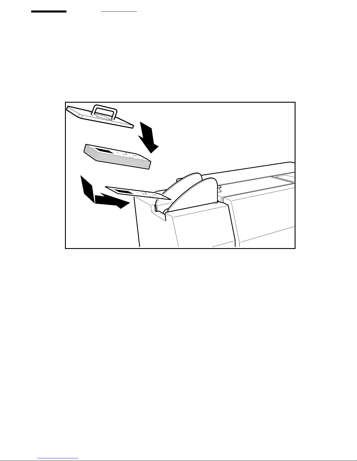
Loading cards
A maximum of approximately 250 aperture cards can be loaded into the input
hopper . A card press is placed on top of the batch of cards to assure a smooth
throughput of cards. The cards are placed in the scanner as shown in the
illustration below. Depending on the setting in the Configuration menu, you
must load the cards face up or face down (see ‘Configuration’ on page 85).
2243
[4] Loading cards
▼ To load a batch of cards:
Place the first card of the batch in the input hopper, sliding it a bit forwards to
1
make sure the card is gliding under the card guide plate.
2 Place the rest of the cards on top.
3 Put the card press on top of the batch of cards.
18 Océ 3000 User Manual
Page 19
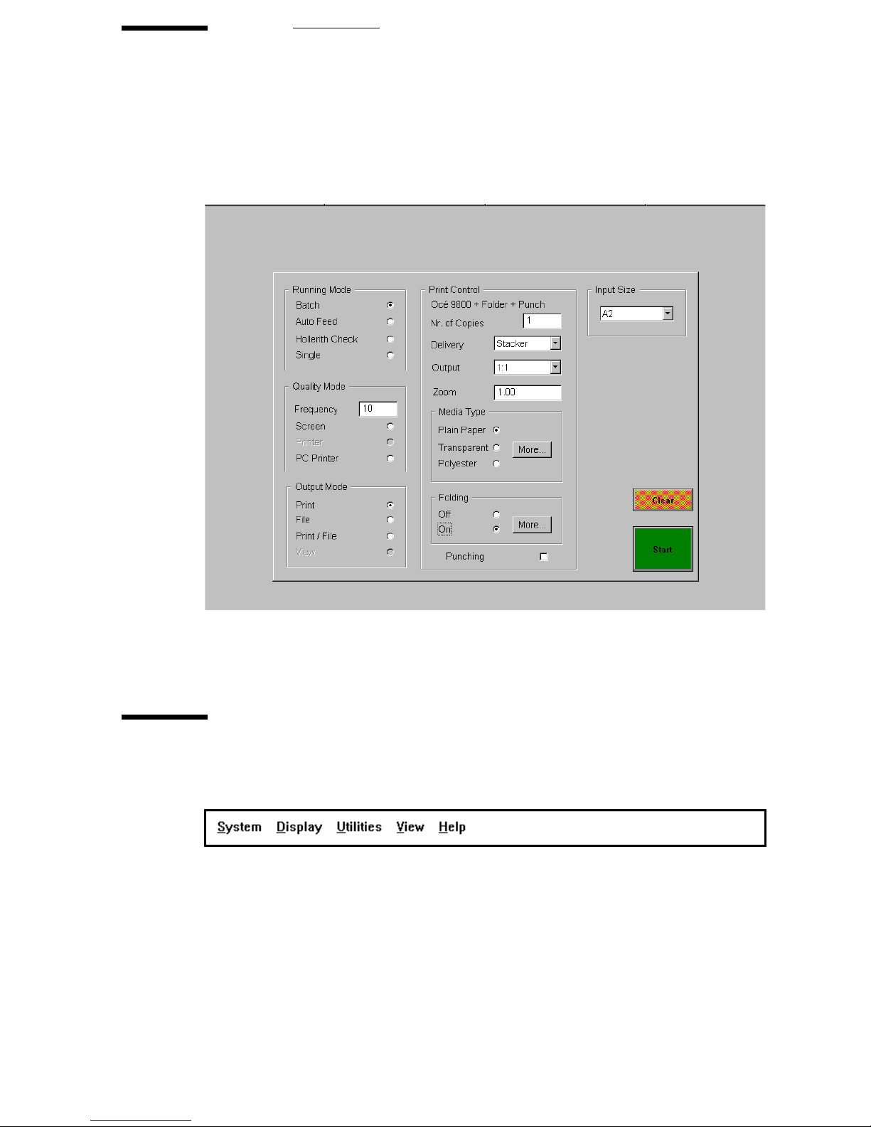
The Control window
When the Océ 3000 Microfilm Scanner Windows application is activated, the
Control window appears on the screen. The following figure displays the
default Control window.
2066.tif
[5] Default Control window
The different parts of this window are described in the following paragraphs.
The option bar
The option bar provides five pull down menus.
[6] The option bar
System This is a pull down menu which contains the exit route for terminating
a scanning session.
Scanning 19
Page 20

Display This pull down menu selects one of the three possible display modes.
All display modes are available during the scanning process and during the
viewing (browsing) after drawings have been scanned. The different display
modes are described in detail in ‘Choosing a display mode’ on page 34.
Utilities This pull down menu provides the Configuration and Clean Drum
options. The Configuration option is described in ‘Configuration’ on page 85.
Clean Drum is described in ‘Cleaning the drum’ on page 98.
View This is a pull down menu allows you to view a selected image data file.
The Viewing mode is described in chapter 4.
Help The Help option provides on-line context sensitive help on all aspects of
the system operation. Clicking the Help option during operation will display
information concerning the process (this option is not available below version
3.1).
The selection buttons
There are four main selection buttons which are placed at the top of the Control
window. Each of these opens a setup dialogue box.
[7] The selection buttons
Scanner setup Clicking the Scanner Setup button brings up the Scanner Setup
window . It provides all the setup tools related to the scanner . Y ou can find more
information in ‘The scanner setup’ on page 44.
Printer setup Clicking the Printer Setup button brings up the Printer Setup
window . It provides all the setup tools related to the printers. Y ou can find more
information in section ‘The printer setup’ on page 71.
File Handling Clicking the File Handling button brings up the File Setup
window. It allows setting up the details of the output files, file naming etc.
More information is in ‘The file handling setup’ on page 88.
Job Management Clicking the Job Management button brings up the Job
Management window . It allows setting up the log file and file size limits for the
job. More information is in ‘The Job Management Menu’ on page 91.
20 Océ 3000 User Manual
Page 21
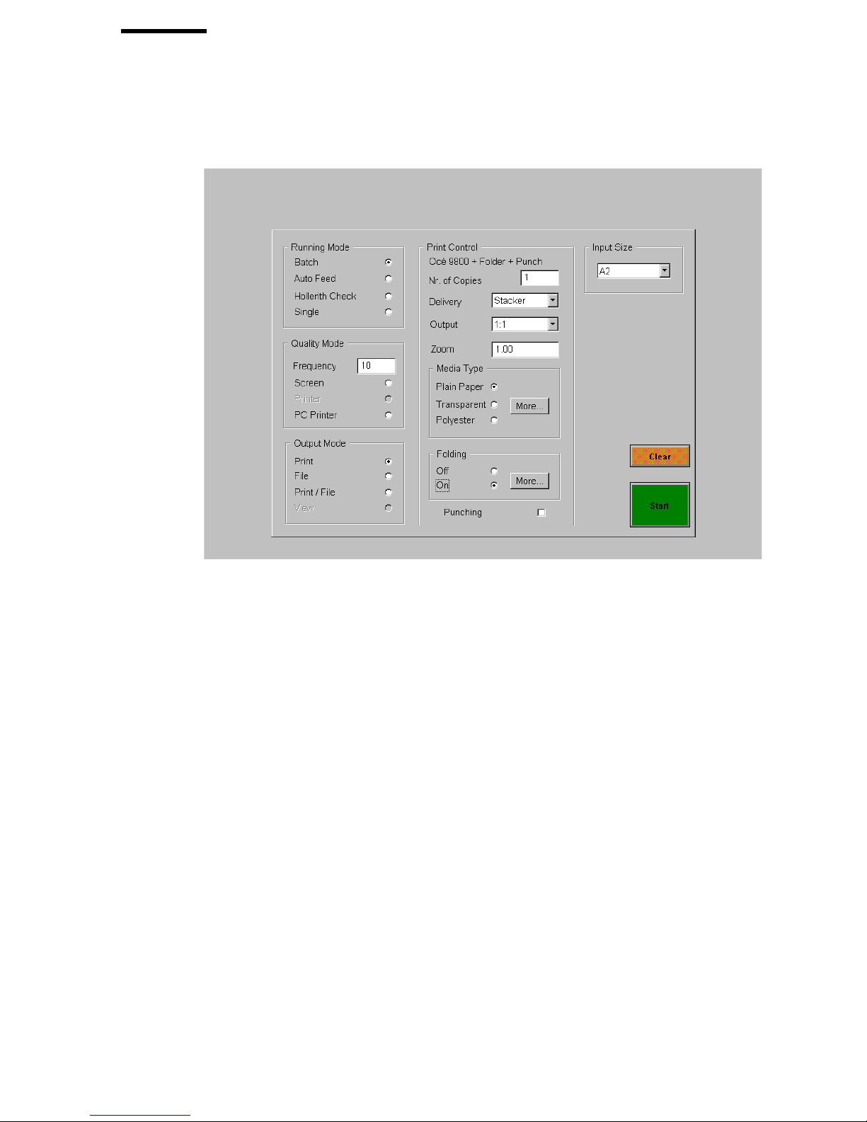
The Control window
The Control window contains five entry boxes to set parameters for the
scanning session and two control buttons for starting the job or clearing the
scanner.
2067.tif
[8] The control window
Running Mode The Running Mode entry box contains four radio buttons,
allowing you to choose from the various scanning modes: Batch, Auto Feed,
Single and Hollerith check.
Quality Mode The Quality Mode entry box is only accessible in Batch running
mode. This mode allows you to automatically pause the scanner after a preset
number of scanned cards, and to check the quality of the scanned images. You
can set the frequency of the Quality Mode and three radio buttons allow you
to choose from the various output settings: Screen, Printer or PC Printer.
Output Mode The Output Mode entry box provides four radio buttons to select
the output: Print, File, Print/File or View.
Input Size The Input Size entry box allows you to specify the size of the image
on the microfilm, or to select Hollerith sizing.
Scanning 21
Page 22

Print Control The Print Control entry box allows you to specify the desired
settings for the selected printer output: the number of copies, the size of the
output print, etc. The look of the Print Control entry box depends on the
selected printer. You can find more information in ‘The printer setup’ on
page 71.
Clear Use this button to clear cards which may be trapped in the scanner.
Start This button starts the Océ 3000 Microfilm Scanner process as selected
(batch or single).
If Hollerith Naming is off, depending of your choice File or Print/File, the
following window appears before scanning starts:
2068.tif
[9] Image file name
This window allows you to define the root of the name for the scanned image
files, and the counter start number . In the example above, the first image file is
‘scan0001’, the second image file is scan0002’ and so on.
If Log File Usage is on, the following window appears before scanning starts:
2069.tif
[10] Log file
This window allows you to set the name for the log file.
After defining log file and file naming, the scanning starts and the window
changes to the Run-Time Display window.
22 Océ 3000 User Manual
Page 23

Scanning in Single mode
The Océ 3000 Microfilm Scanner feeds, scans and displays one card and waits
for your command to print, file, reject or rescan the image. After the image has
been accepted, the card is ejected into the output hopper.
The image of each card is displayed on the run-time display window. The
machine pauses and you can inspect the image. You can now change the
scanning parameters and then rescan the card until you obtain a satisfactory
image. When you are satisfied with the displayed image, you can accept the
image and send it to the required output. If the output mode is set to print, file
or print/file, the system automatically produces the desired output. In the V iew
mode, no output is generated.
Cards with unknown Hollerith codes
In Single and Auto Feed mode, you can add a string of Hollerith data to cards
without Hollerith punches or with unknown Hollerith codes. The special
‘Hollerith Add Mode’ in the Configuration menu is designed for this purpose
(see ‘Configuration’ on page 85). When ‘Hollerith Add Mode’ is on, the
software generates a string of Hollerith data for a card. This string of data is
displayed on the Run-Time Display window , placed in the header of the image
data file and stored in the LOG file, if activated.
Settings in the Control window
Before activating the scanning process, you set the scanning control in the
Control window.
▼ To start a scanning session in Single mode:
Click the Single button in the Running Mode entry box.
1
2 Select the Input Size or select Hollerith Sizing.
3 In Configuration of the Utilities pull down menu, set Hollerith Add Mode on
or off as required.
4 Select the desired Output Mode.
5 If the output mode is set to Print or Print/File, set the Print Control settings as
required.
Scanning 23
Page 24

6 Place the aperture card in the input hopper of the scanner.
7 Click the Start button to start the scanning.
8 If required, set the names for image files and log file (see figures 9 and 10 on
page 22).
The system switches to the Run-Time Display window (see figure 12 on
page 30).
24 Océ 3000 User Manual
Page 25
Scanning in Batch mode
The Océ 3000 Microfilm Scanner automatically feeds and scans a batch of
cards placed in the input hopper of the scanner. After a card has been ejected
into the output hopper, the scanner automatically feeds the next card.
The image of each card is displayed on the Run-Time Display window as the
batch process proceeds. When the output mode is set to Print, File or Print/File,
the system automatically produces paper copies and/or data files for each card
scanned.
All the necessary controls and functions are provided in the Control window
of the Océ 3000 Windows application software so that scanning can be
performed automatically, requiring your intervention only for loading and
unloading supplies of cards.
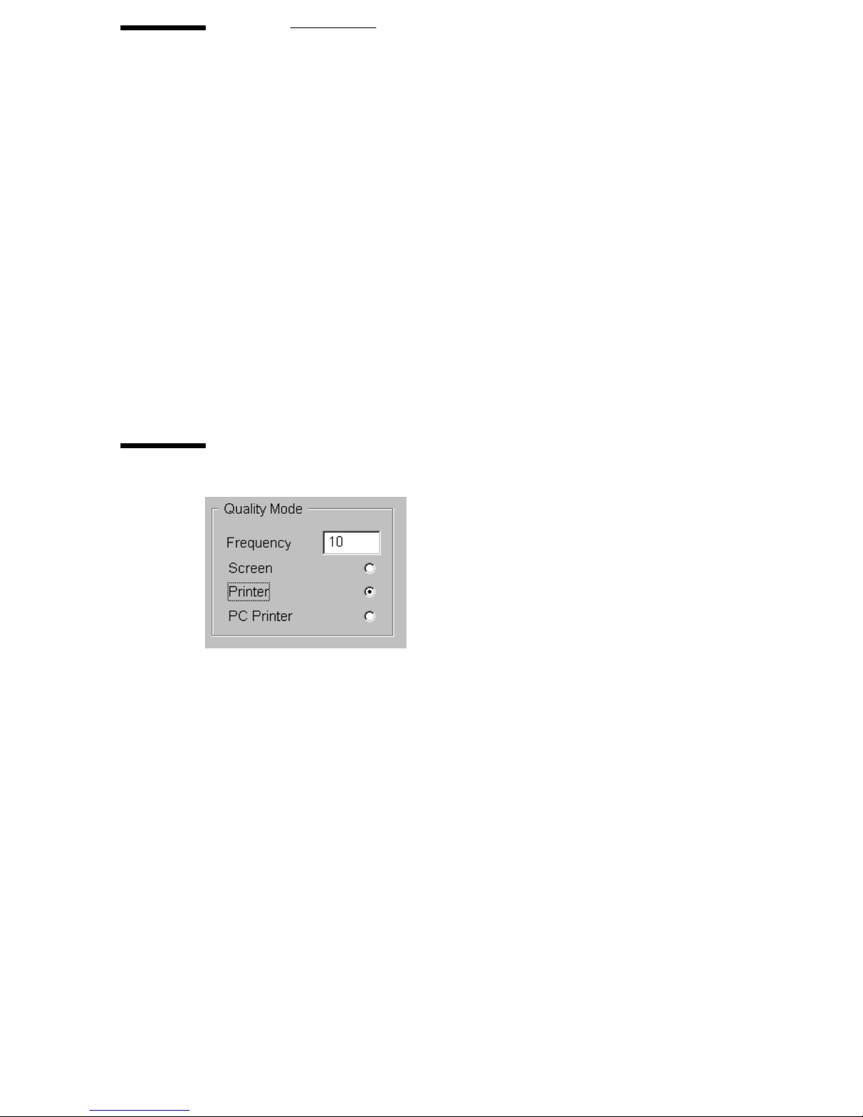
Quality mode
2070.tif
[11] Quality mode
When using the Quality mode feature, scanning proceeds automatically for a
predefined number of cards. This number is the ‘frequency’ of the Quality
mode. If you set the frequency between 1 and 250 to, e.g., 10, the scanner
automatically scans and generates outputs for 9 cards. A special output can be
created for every tenth card, allowing you to check the quality of the images.
The following output options are available for the Quality mode:
■ Screen: you can view every tenth card on the window.
■ Printer: you can make a print of every tenth card on the selected printer.
■ PC Printer: you can make a print of every tenth card on a local Windows
printer.
Scanning 25
Page 26

Note: The Printer and PC Printer options are not available when the Output
mode is set to Print or Print/File. The PC Printer option is also not available
when the PC printer is set as default printer.
Settings in the Control window
Before starting the scanner, you set the scanning controls in the Control
window.
▼ To start a scanning session in Batch mode:
Click the Batch button in the Running Mode entry box.
1
2 Enter the frequency for the Quality mode. Select the desired output mode of
the Quality mode. If you do not want a quality check, take care the options
buttons are empty (not black - not on).
3 Select the Input Size or select Hollerith sizing.
4 Choose the desired output mode in the Output Mode entry box.
5 If the output mode is Print or Print/File, set the Print Control settings as
required.
6 Place the batch of aperture cards in the input hopper of the scanner.
7 Click the Start button to start the scanning session.
8 If required, set the names for image files and log file (see figure 9 on page 22
and see figure 10 on page 22).
The system switches to the Run-Time Display window (see figure 12 on
page 30).
26 Océ 3000 User Manual
Page 27

Scanning in Auto Feed mode
The Océ Microfilm Scanner feeds, scans and displays one card at a time and
awaits your command to print, file, reject or rescan the card. After the image
has been accepted, the card is ejected into the output hopper of the scanner. The
system automatically feeds and scans the next card and displays the image on
the screen.
The image of each card is displayed on the Run-Time Display window. The
scanner pauses and you can inspect the image. You can now change the
scanning parameters and then rescan the card until you obtain a satisfactory
image. When you are satisfied with the displayed image, you can accept the
image and send it to the required output. If the output mode is set to Print, File
or Print/File, the system then automatically produces the desired output. In the
View mode, no output is generated.
Cards without Hollerith punches
In Single and Auto Feed mode, you can add a string of Hollerith data to cards
without Hollerith punches. The special ‘Hollerith Add Mode’ in Configuration
of the Utilities pull down menu is designed for this purpose (see
‘Configuration’ on page 85). When ‘Hollerith Add Mode’ is on, the software
generates a string of Hollerith data for a card. This string of data is displayed
on the Run-Time Display window, placed in the header of the image data file
and stored in the LOG file if activated.
Settings in the Control window
Before starting the scanner, you set the scanning controls in the Control
window.
▼ To start a scanning session in Auto Feed mode:
Click the Auto Feed button in the Running Mode entry box.
1
2 Select the Input Size or select Hollerith Sizing.
3 In Configuration of the Utilities pull down menu, set Hollerith Add Mode on
or off as required.
4 Select the required Output Mode.
Scanning 27
Page 28

5 If the output mode is set to Print or Print/File, set the Print Control settings as
required.
6 Place the aperture cards in the input hopper.
7 Click the Start button to start the scanning session.
8 If required, set the names for image files and log file (see figures 9 and 10 on
page 22).
The system switches to the Run-Time Display window (see figure 12 on
page 30).
28 Océ 3000 User Manual
Page 29

Scanning in Hollerith Check mode
The Océ 3000 Microfilm Scanner feeds a card, scans the card and displays the
Hollerith data in the Run-Time Display window . Errors in the Hollerith coding
can be corrected with edit in the Run-Time Display window.
Note: This mode is not useful when the aperture cards are not punched.
Settings in the Control window
Before starting the scanner, you set the scanning controls in the Control
window.
▼ To start a scanning session in Hollerith Check mode:
Click the Hollerith Check button in the Running Mode entry box.
1
2 Select the Hollerith in the Input Size entry box.
3 Select the required Output Mode.
4 If the output mode is set to Print or Print/File, set the Print Control settings as
required.
5 Place the aperture cards in the input hopper.
6 Click the Start button to start the scanning session.
7 If required, set the names for image files and log file (see figures 9 and 10 on
page 22).
The system switches to the Run-Time Display window (see figure 12 on
page 30).
Scanning 29
Page 30
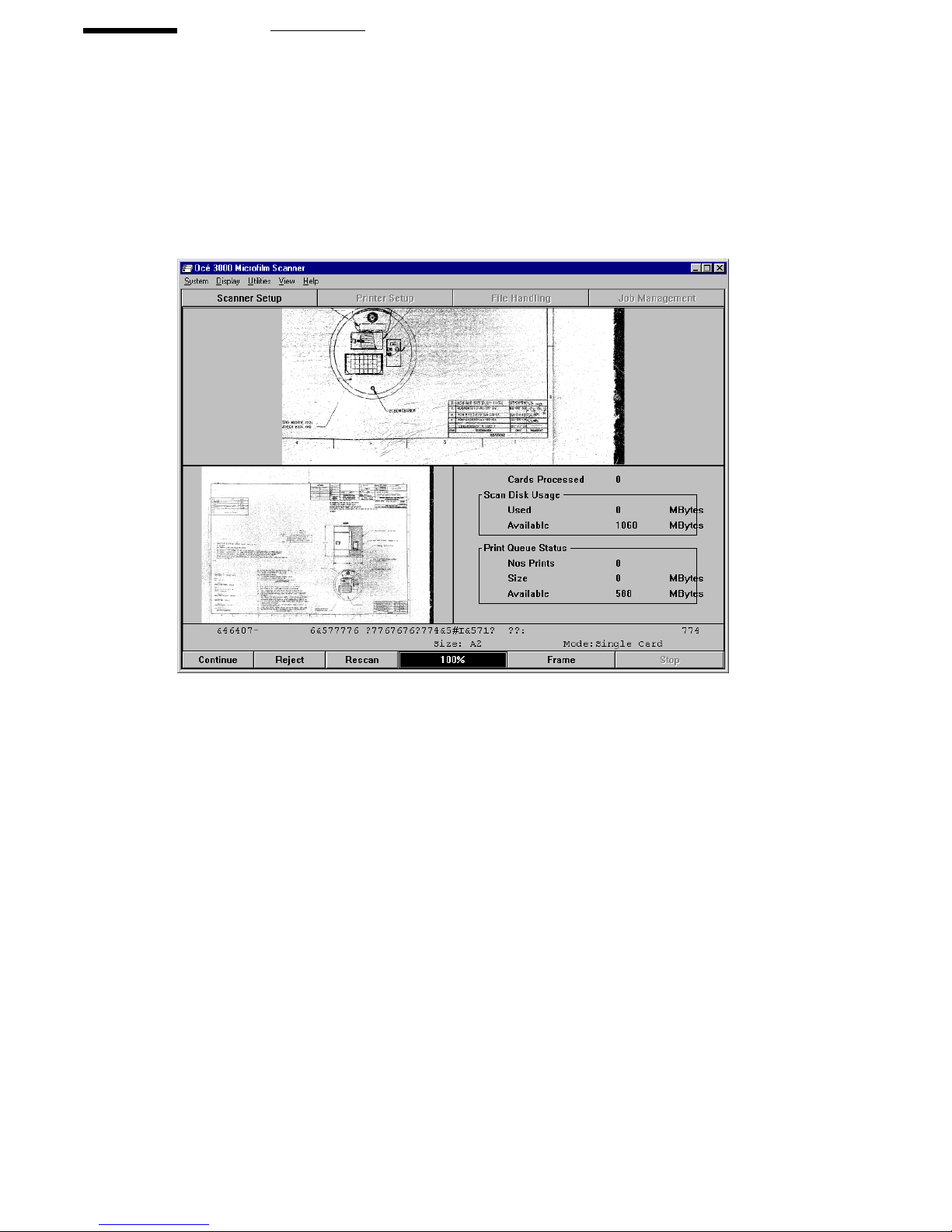
The Run-Time Display window
The Run-Time Display window appears when you click on the Start button on
the Control window. The display mode depends on the setting in the Display
menu. The illustration below shows an example of a Run-Time Display
window in Batch mode.
2071.tif
[12] Run-Time Display window (Dual Mode)
While scanning is paused, the Scanner Setup window can be called to change
the imaging parameters and the drawing size of the scan. In case a different
display mode is preferred, you can choose full, enlarged or dual. T o change the
display mode see section ‘Choosing a display mode’ on page 34.
The button bar at the bottom of the window allows you to control the scanning
session.The layout of the button bar depends on the running mode and the
output mode.The following buttons can appear:
■ File/Print/Print+File
■ Continue
■ Reject
■ Rescan
■ Accept
30 Océ 3000 User Manual
Page 31

■ Edit
■ Frame
■ Pause
■ Stop
More detailed information on the buttons is given below:
File/Print/Print+File This button will appear, when on the Control window in
the Running Mode entry box Single, Hollerith Check or Auto Feed, is selected.
The button allows you to accept the scanned image and generate the desired
output. The card is ejected into the output hopper and the system returns to the
Control window.
Continue This button will appear in three cases:
1 when on the Control window in the Running Mode entry box Batch is selected
2 when on the Control window in the Output Mode entry box View is selected
3 after selecting pause in stead of File/Print/Print+File
Reject This button rejects the scanned image. No output is generated and the
system returns to the Control window. The card is ejected from the scanner.
Rescan Should the image not be optimal from the first time, you can change
the imaging parameters and scanning resolution and then rescan the card to
obtain a better result.
Accept In Hollerith Check mode, this button is used to accept the displayed
Hollerith code.
Edit This button allows you to correct errors in the Hollerith coding. The
Hollerith Check window will appear to make the corrections.
▼ To edit the Hollerith data:
Click Edit in the Run-Time Display window.
1
The Hollerith data string as read from the card is displayed. You can edit the
name for the scanned file and the drawing size settings in the entry fields.
Scanning 31
Page 32

A window similar to the following example pops up:
2072.tif
[13] Hollerith editing
2 If required, change the file name and the drawing size settings.
3 Click Update and the scanning proceeds with the changed settings.
Frame The Frame option can be used to rescan the image, defining the
scanning area yourself.
▼ Defining a new scanning area, using the Frame option
Click the Frame button at the bottom of the screen.
1
The following window will appear:
[14] Frames window
2 Click on a standard frame size, or select Region to draw your own frame.
Note: If you need a predefined frame size that is not shown in the Frames
window, click More to get a list of all known sizes.
3 If you have selected a standard frame size, push the left mouse button, move
the frame to the required position, and release the button.
32 Océ 3000 User Manual
Page 33

4 If you have selected Region, move the mouse to a corner of the frame you want
to draw. Push the left mouse button, move the mouse to draw the frame, and
release the button.
5 Click Rescan at the bottom of the screen.
The area inside the defined frame will be rescanned.
Note: To go back to the original image, click Frame again. The Frames
window will disappear. Then click Rescan to get the original image.
Pause This button pauses the scanning and enables the continue button.
Stop This button stops the scanning and returns to the Control window. No
output is generated. The card is ejected from the scanner.
Scanning 33
Page 34

Choosing a display mode
Either during the scanning process or during the file viewing (browsing) after
drawings have been scanned, you can display the images in three different
modes. The three display modes are available in the Display pull down menu.
They are described below.
Full Image
This option provides a full screen display of the whole image, scaled to fit the
available space in the window . The ‘zoom and pan’ facility is not available in
this mode.
2074.tif
[15] Run-Time Display window with a Full Image
34 Océ 3000 User Manual
Page 35

Enlarged
This option is a full screen display of a selected area of the image, scaled to fit
the available space in the window.
2075.tif
[16] Run-Time Display window with an Enlarged Image
You select the image area to be displayed using the ‘zoom and pan’ facility.
The zoom ratio defines the level of detail of the image to be displayed, and the
pan position defines which part of the image is displayed.
The display area and zoom factor are retained for the duration of the scanning
session so that the same area of other images using the Enlarged Display will
be displayed. When switching the Océ 3000 Microfilm Scanner on, the display
defaults to the full image.
Scanning 35
Page 36

Dual
This option provides a mixed screen display with three parts.
2076.tif
[17] Run-Time Display window with a Dual Image
The first part shows an enlarged section of the image in the upper part of the
screen. The second part displays the full image scaled to fit the bottom left part
of the screen. The third part is the bottom right part of the screen. It displays
the status of the scanning session during the scanning process. It is empty in
Viewing mode.
The status section of the Dual display consists of three subjects:
■ Cards Processed shows the number of cards already scanned in the batch and
autofeed mode.
■ Scan Disk Usage is giving the disk capacity used and free capacity in MB.
The scan disk is the disk on which image data files are stored.
■ Print Queue Status shows the number of prints in queue, the total used
capacity and free capacity in MB of the print spooling disk.
The image displayed in the upper part of the window, may be scaled and
zoomed by the ‘zoom and pan’ facility. The display area and zoom factor are
retained for the duration of the current scanning session so that the same area
36 Océ 3000 User Manual
Page 37

Zoom
of other drawings using the Dual Display mode will be displayed. On
switching the Océ 3000 Microfilm Scanner on, the zoomed display is set to the
bottom right hand corner of the image by default.
In Enlarged or Dual Display mode, the zoom and pan facility allows you to
take a closer look on a defined area of the image displayed on the screen. This
facility is available both during scanning and during browsing.
Zooming Clicking the left mouse button defines the top left corner of the area
to enlarge. Dragging the mouse with the button still depressed defines a
rectangular area. The aspect ratio of this rectangle is the same as for the display
window .
Releasing the left mouse button again displays the defined area.
Clicking the right mouse button toggles between the enlarged image and the
full image display. An alternative method is to use the F6 key.
When zoomed, the displayed area may be moved on the screen using the scroll
bars or the cursor keys.
An alternative method of zooming is to use the “+” and “–” keys on the
numeric keypad. In this case, the area in the centre of the display window is
enlarged.
Scanning 37
Page 38

38 Océ 3000 User Manual
Page 39

Chapter 4
The Viewing mode
Océ 3000
User Manual
39
Page 40

Viewing image files
The V iewing mode is a special mode for viewing scanned image files that are
stored in an image directory.
Click the View button in the option bar to enter the viewing function.
Click the Select option in the V iew pull down menu to open a file selection box
showing all the file names of a specified type in the current data directory:
2077.tif
[18] File selection
You select a file by double clicking the file name or you can select more files
at once see page 41.
40 Océ 3000 User Manual
Page 41

The view screen
Once a file has been selected for viewing, it is displayed on the screen. Y ou can
change the Display mode in the Display pull down menu. The following
illustration is an example of a View screen:
2078.tif
[19] The View screen
If more than one file is selected, you can scroll to:
■ the next image
■ the previous image
■ auto: after approx. 3 seconds the next image appears automatically on the
screen
■ stop: the stop button is to stop the automatic scrolling (this button is only
enabled, when ‘Auto’ is in use)
Printing in View mode You can print the image on the screen, by selecting one
of the print options in the View pull down menu:
The Viewing mode 41
Page 42

■ Print
The whole image will be printed without zoom factor.
■ Print Enlarged
Only the selected frame will be printed, using a zoom factor to fill up the
chosen paper format.
Leaving the View mode You leave the View mode by selecting Exit view in
the View pull down menu.
42 Océ 3000 User Manual
Page 43

Océ 3000
User Manual
Chapter 5
Setting up the Océ 3000
Microfilm Scanner
This chapter explains how to set the configuration of the
Océ 3000 Microfilm Scanner and peripherals.
43
Page 44

The scanner setup
Click the Scanner Setup button to display the Scanner Setup window. The
Scanner Setup window contains entry boxes for all parameters necessary to
obtain scanned images of high quality . The Scanner Setup window is shown in
the illustration below:
2079.tif
[20] Scanner Setup
The window consists of five different cards:
■ Imaging
■ Drawing Size
■ Hollerith Control
■ Predefined File Name
■ Automatic Card selection
Each card can be selected by clicking its label. Besides these entry boxes, the
window also contains an on-line help button and two control buttons:
■ The OK button allows you to update the scanner setup after changing the
parameters.
■ The Cancel button allows you to exit the Scanner Setup window without
updating the parameters.
■ The Help button allows you to enter the help screen of the Scanner setup.
44 Océ 3000 User Manual
Page 45

Imaging
The Imaging card sets up suitable image processing parameters for the type of
cards to be scanned. You can define a group of parameters and save it in a
template for future use. Up to nine different templates can be predefined for
future use.
2080.tif
[21] Imaging
The setting of the imaging parameters is described in detail below.
Automatic Background Compensation Automatic Background
Compensation (
ABC) sets the image background automatically to white. In
most cases this improves the image quality. Some images will look better in
the original background. In this case, switch
Lighter / Darker With the scroll bar the black/white level with which an image
ABC off.
is processed can be changed if in standard mode.
Note: When File size optimization is selected (see Mode), ABC is
automatically switched on and the scroll bar cannot be moved.
Mode This setting is for handling images with little contrast. There are three
scanning modes to choose from by clicking the appropriate radio button:
■ File Size Optimization: use this mode to print high contrast images when a
file size should be minimized as far as possible. The number of grey values
will be limited.
Setting up the Océ 3000 Microfilm Scanner 45
Page 46

■ Standard: use this mode for good quality images of normal originals.
■ Photo: use this mode when the originals contain halftone information or
other low-contrast features such as photographs.
Film Inverse Use this option to set the scanner for negative or positive looking
images.
■ The option is ON: The film polarity is positive (black line on white
background).
■ The option is OFF: The film polarity is negative (white line on black
background).
Load This enables a previously loaded set of image parameters to be recalled
for use.
Save This enables the current set of parameters to be saved for future use. Up
to nine different sets can be stored.
Delete This button enables you to remove a set of imaging parameters from
the setup list.
▼ To load a predefined imaging setup:
Open the Scanner Setup window.
1
2 Select the Imaging card.
3 Click the Load button at the bottom of the Imaging card.
On pressing this button, the following window is displayed:
2081.tif
[22] Loading an imaging setup
All predefined setups are listed. The example above displays two options.
‘Working’ stands for the setup as it is currently defined in the Imaging entry
box. Selecting this option leaves the imaging setup unchanged.
4 Click the desired setup.
5 Click OK.
The parameters defined in the setup are automatically fitted in the Imaging
window.
46 Océ 3000 User Manual
Page 47

▼ To save an imaging setup:
Open the Scanner Setup window.
1
2 Select the Imaging card.
3 Set the parameters as required in the Imaging card.
Set the illumination level, Film Inverse,
4 Click the Save button.
The following window appears on the screen:
2082.tif
[23] Saving an imaging setup
5 Type the name of the new setup in the Name entry box.
6 Click the Save button to add the new setup to the list.
▼ To delete an imaging setup:
ABC and Mode to the required settings.
Open the Scanner Setup window.
1
2 Select the Imaging card.
3 Click the Delete button.
The following window appears on the screen:
2083.tif
[24] Deleting an imaging setup
4 Click the setup you want to delete.
5 Click OK to delete the setup.
Drawing Size
In the Drawing Size card you can set the parameters related to the drawings to
be scanned or printed as defined in the drawing size file.
Setting up the Océ 3000 Microfilm Scanner 47
Page 48

2084.tif
[25] Drawing Size
The details of the Drawing Size card are described in detail below.
Drawing size Here you can select a specific drawing size from the drawing
size file.
When selecting one of the drawing sizes, the values for reduction ratio,
drawing width and drawing length are filled in automatically and they are
dimmed. To edit the drawing size (see page 49).
In the software one file with standard definition of file sizes is available
(DWGSIZES.DRG).
48 Océ 3000 User Manual
Page 49

Edit drawing Size File You can create drawing size files, other than the
standard drawing sizes listed in the DWGSIZES.DRG file. You can define the
input size, reduction ratio, drawing width and length and print size for your
personal requirements.
2085.tif
[26] Drawing Size File
After clicking the Edit File button in the ‘Drawing Size File’ entry box, the
following window will appear.
2086.tif
[27] Edit Drawing Size File window
Setting up the Océ 3000 Microfilm Scanner 49
Page 50

This window contains four main parts:
■ Drawing Size
■ Drawing Size File
■ Units
■ Control buttons.
Drawing Size This part of the window defines the name of the drawing size,
the reduction ratio, the drawing width and length, the X and Y offset and the
print size. Any name up to 8 characters will do.
▼ To add a new drawing size:
Open the Scanner Setup window.
1
2 Select the Drawing Size card
3 Click the Edit File button to open the Edit Drawing Size File window.
4 Click New Size.
5 Enter a name for the new size in the upper right entry box.
6 Choose the units to work with.
7 Enter the values for reduction ratio, drawing width and drawing length in the
appropriate entry boxes.
8 Click Update to add the drawing size to the Drawing Size File.
▼ To delete a drawing size:
Open the Scanner Setup window.
1
2 Click the Edit File button to open the Edit Drawing Size File window.
3 Select the size to delete in the size list.
2087.tif
[28] Deleting a drawing size
4 Click Delete Size.
5 Click Update.
50 Océ 3000 User Manual
Page 51

Reduction ratio For standard drawing sizes, the reduction ratio value is
taken from the Drawing Size File. This parameter can be
altered manually when this value deviates from the
standard reduction factor . The reduction ratio may be set
in the range of 5.00 to 36.00.
Drawing width This is the width of the image on the microfilm, in
millimetres or inches, according to the setting in the
Drawing Size File. This parameter may only be altered
manually when
NON-STD size has been selected.
Drawing length This is the length of the image on the microfilm, in
millimeters or inches, according to the setting in the
Drawing Size File. The drawing length may only be
altered manually when the
NON-STD size has been
selected.
X and Y offsets This is the number of microns by which the image in the
microfilm on the card is known to be off the centre of the
film.
Note: These windows are available in the Run-Time
Display.
Unless the image is grossly or deliberately offset from its
normal centralised position, it is better to use the Rescan
option rather than changing the position of the scan
window. If the scan window position does need to be
changed, you can alter the X and Y offset values. Both
offsets can be adjusted between - 5000 and + 5000.
Print size The print size is the size used for printing the scanned
image. When selecting the size of the original image on
the microfilm, the system automatically sets the print size
to the same size. You can select a print size other than the
drawing size if required. The size A4 or E can exist as
portrait.
Setting up the Océ 3000 Microfilm Scanner 51
Page 52

Drawing Size File This part of the window defines the name of the Drawing
Size File and the current scanning resolution for all drawing sizes in this file.
Any name up to 8 characters will do.
Resolution The resolution may be set to any value between 100 dpi
and 400 dpi.
Units In this part of the window you can enter values in millimetres or inches.
Control buttons
Update The Update button stores the edited drawing size in the
drawing size file.
Cancel The Cancel button allows you to exit the window without
making any changes.
52 Océ 3000 User Manual
Page 53

General Hollerith information
The hollerith reader possibilities of the Océ 3000 Microfilm scanner are
experienced to be the most complicated part of the product.
Basic hollerith explanation Many organisations punch their cards to easy their
identification. Punched hollerith cards have the big advantage that they can be
recognized through, so called, hollerith readers. The Océ 3000 Microfilm
scanner has an intelligent built-in hollerith reader.
The hollerith punches in the card represent numbers or characters. These
numbers/characters refer often to the drawing number and the original format
of the drawing. Also other information can be coded via the punches.
To understand the interpretation of the holes in the cards both the punches in
the vertical direction (column) as in horizontal direction (row) must be
explained (see figure 29).
[29] Hollerith card
The punches in the vertical direction (column) The height of the card and the
size of the punch itself is limited to 12 possible positions of the punch in the
vertical direction.
Numbers are represented by the specific position of ONE punch in the vertical
direction. Characters are represented by the specific position of TWO or
THREE punches in the vertical direction. The position of the punch or punches
in the vertical direction are based on world-wide standards. This means that the
1 is always punched in row 1, the 2 in row 2 etc. The A is always punched in
row -2 and row 1. The B is always punched in row -2 and row 2 etc. (see figure
Setting up the Océ 3000 Microfilm Scanner 53
Page 54

34). The M, for example is always in row -1 and row 4, the Z in row 0 and row
8.
[30] Hollerith punches in vertical direction
The correct identification of the punches is already programmed in the
hardware of the hollerith reader in the scanner and needs no further attention.
The punches in the horizontal direction (row) The interpretation of the
numbers and characters in the horizontal direction (row) is company or project
specific. Every company had made the structure of the punched information in
the horizontal direction according to their specific (internal0 demands.
Sometimes more structures than one exist:
■ because also cards from other companies/subcontractors are in use
■ because in time the card structure changed to meet new demands
54 Océ 3000 User Manual
Page 55

[31] Hollerith punches in horizontal direction
In this example the 8 is the card key , SMU5803 is the drawingnumber and A0
is the original drawing format. In total these 55 to 60 punches represent
information directly related to the filmed drawing on the card. This could be
everything. The drawing number (eventually with a release number) and the
size of the original drawing are the most important ones.
Hollerith codes in the Océ 3000 To benefit from the punched info the
Océ 3000 Windows application needs to be set up to interpret the hollerith
punches. Since this information will be stored in a so called Hollerith control
file, programming of it has to be done once:
■ how a company/project specific card can be identified (the so called ‘card
key’
■ on which positions the drawing number can be read (‘file name’)
■ on which positions and how the drawing format can be identified and
interpreted (‘size key’)
Company employees, directly responsible for the indexing or coding of the
MF-cards must be able to clarify the way the cards are punched.
The card key is important because when scanning the Océ 3000 scanner needs
to detect automatically the correct position of the drawing number and/or
drawing format of that specific card.
If all cards are punched in the same way the card key is not necessary. In this
case type ALL_CARDS where normally the card key is inserted. This will
switch off the card key function (see figure 38 on page 60).
Setting up the Océ 3000 Microfilm Scanner 55
Page 56

Hollerith Control
Hollerith control allows you to fetch the information for size and file name for
the scanned images from the cards.
Approximate 1000 Hollerith files can be generated. It is possible to define up
to approximate 1000 different Hollerith file structures within 1 Hollerith file
which can be activated at the same time.
The Hollerith Control card consists of three main parts:
■ Hollerith sizing
■ Hollerith naming
■ Control File.
2088.tif
[32] Hollerith Control card
Hollerith sizing When this option is on, the Hollerith reader in the scanner
reads the information for the size of the scanned images from the cards, in
accordance with the selected Hollerith Control File.
When this option is off, you select the appropriate sizes in the Edit Drawing
Size File window , or in the Control window before starting a scanning session.
Hollerith naming When this option is on, the Hollerith reader in the scanner
reads the name for the data files for scanned images from the cards, in
accordance with the selected Hollerith Control File.
56 Océ 3000 User Manual
Page 57

When this option is off, the system prompts you to enter a name for the
scanned images files when starting the scanning session.
Note: When you select ‘Hollerith’ as input size in the Control window, the
option ‘Hollerith sizing’ is automatically switched on. ‘Hollerith Naming’
however remains off.
Editing the Hollerith Control File When you click the Edit File button in the
Hollerith Control entry box, the Edit Hollerith Control File window will
appear.
2089.tif
[33] The Edit Hollerith Control File window
This window exists out of the following parts:
■ The name of the Hollerith Control File
■ Card Keys
■ Filename
■ Size Keys
■ A table to switch on/off the Hollerith elements
Setting up the Océ 3000 Microfilm Scanner 57
Page 58

■ A number of selections and control buttons.
2090.tif
[34] Display elements entry box
The radio buttons in the Display elements entry box select which Hollerith
elements are displayed in the Hollerith Elements window: the elements
containing the card key information, the name of the image or the size
information.
▼ To define a Hollerith Control File:
T o store the Hollerith elements in a file, first a filename for the Hollerith control
must be defined.
1 Insert the filename (max. 8 characters) and the extension .hcf in the filename
entry box. In this example the filename is control.hcf.
2091.tif
[35] The name of the Hollerith Control File
2 To save the filename click update to go back to the Scanner setup.
3 Choose the new created Control filename in the Hollerith Control entry box of
the Scanner Setup window to return to the Edit Hollerith Control File window .
Note: Up to a 1000 different Hollerith Control Files can be defined.
58 Océ 3000 User Manual
Page 59

▼ To add a new Card Key:
If the Hollerith structure per card or group of cards differ, a card key can be
identified so the Hollerith reader can recognize the various Hollerith structures
with regard to the drawing number and drawing format (size key). If only one
Hollerith structure is applicable (all the cards are punched in the same way)
type ALL_CARDS (see figure 36).
[36] The card key in this example is represented by A & B in column 1 & 2
To insert the place the Hollerith elements, representing the key, you have to
follow this procedure.
1 Click the Card Key radio button in the Display elements entry box (see
figure 33 on page 57) or (see figure 34).
2 Click New Card Key in the Card Key window.
2092.tif
[37] To create a New Card Key
3 T ype the name (the key of a specific hollerith structure) of the Card Key in the
entry field (in this example T ype A and B). In the Hollerith Elements window,
select the elements that contain the new Card Key (in this example click
Hollerith element 1 and 2 in the Edit Hollerith Control FIle screen, (see
figure 33).
The number of Hollerith elements must equal the number of characters in the
name of the Card Key (The length of the card key is not limited).
Setting up the Océ 3000 Microfilm Scanner 59
Page 60

4 Click Update to confirm and go back to the Scanner Setup window . If you want
to edit more in this window click Update later on.
Note: Up to a 1000 different Card Keys can be defined within one Hollerith
Control File.
▼ No Card Key (ALL_CARDS):
If no card key is used type ALL_CARDS in the Card Keys entry box. Beware
that all Hollerith elements are switched off. Continue with inserting the
filename and the size keys. The card key function is now disabled.This setting
can be stored under any Hollerith control filename (********.hcf).
2093.tif
[38] View of the Edit Hollerith Control File window in case no card key is active
60 Océ 3000 User Manual
Page 61

▼ To delete a Card Key:
Click the Card Key radio button in the Display window (see figure 38).
1
2 In the Card Key list, select the key you want to delete.
2094.tif
[39] Deleting a Card Key
3 Click Delete Card Key in the Card Keys window.
4 Click Update to confirm and go back to the Scanner Setup window . If you want
to edit more in this window click Update later on.
Note: You can not delete the last card key.
Setting up the Océ 3000 Microfilm Scanner 61
Page 62

▼ To edit the File Name:
To read the file name automatically from the card, the place of the file name
must be defined.
[40] The filename in this example is represented by the Hollerith elements 4 to 11
Figure 40 shows an example of a card with the Hollerith elements representing
the drawing number 12345678 of the microfilmed drawing in position 4 to 11.
To insert the place of the Hollerith Elements of the filename (mostly the
drawing number) follow the next procedure.
1 Click the File Name radio button in the Display elements entry box in the Edit
Hollerith Control File window.
2095.tif
[41] In this example the filename will be read in the Hollerith elements 4 to 11
62 Océ 3000 User Manual
Page 63

2 In the Hollerith Elements entry box, select the elements that contain the file
name. In this case click the Hollerith Elements 4 to 11 in the Edit Hollerith
Control FIle window (see figure 41 on page 62). As a DOS-file name can
contain maximum 8 characters, you can select a maximum of 8 Hollerith
elements for the file name.
3 Click Update to confirm and go back to the Scanner Setup window . If you want
to edit more in this window click Update later on.
Setting up the Océ 3000 Microfilm Scanner 63
Page 64

▼ To add a new Size Key:
Within a specific Hollerith structure different drawing formats are common.
The size key function will identify the various formats of cards within the same
hollerith structure.
[42] The size key in this example is represented by the hollerith elements 79 and 80. Any drawing
size can be interpreted
Figure 42 shows an example of a card with the Hollerith elements representing
the format of the microfilmed drawing in position 79 and 80. In this example
an A2. To insert the place of the Hollerith Elements of the size keys (drawing
formats) follow the next procedure.
1 Click the Size Key radio button in the Display elements entry box:
2096.tif
[43] Hollerith Control File: editing size keys
64 Océ 3000 User Manual
Page 65

2 Click the New Size Key in the Size Keys entry box, in this case type or look
for A2.
3 Choose in the Drawing Size a size which represents the size key.
2097.tif
[44] The Size Keys settings
4 In the Hollerith Elements window , click the elements that contain the new Size
Key. In this example click the elements 79 and 80 (see figure 43).
Note: The number of Hollerith elements must equal the number of
characters in the name of the Size Key.
Note: If ‘0’ is chosen for the number of copies the number of copies in the
control scr een is fr ee. If another number than ‘0’ is chosen this number will
overrule the number of copies in the control screen.
Note: The activated drawing size file in the Scanner Setup menu is the one
which will be activated here. To change resolutions or add specific drawing
formats you first have to edit the drawing size file (see section “Edit
drawing Size File” on page 49).
5 Select the other drawing format related elements in the Size Keys entry box
(similar to procedure of the editing in the Drawing Size entry box in the
Scanner Setup window, see section “Drawing Size” on page 47).
6 Click Update to confirm and go back to the Scanner Setup window . If you want
to edit more in this window click Update later on.
Setting up the Océ 3000 Microfilm Scanner 65
Page 66

▼ To delete a Size Key
Click the Size Key radio button in the Display window.
1
2 In the Key list, select the Size Key you want to delete.
2098.tif
[45] Deleting a Size Key
3 Click Delete Size Key.
4 Click Update to confirm and go back to the Scanner Setup window . If you want
to edit more in this window click Update later on.
Note: You cannot delete the last size key.
66 Océ 3000 User Manual
Page 67

Predefined File Name
You can specify under which name the scanned image is to be saved in a file:
■ Hollerith naming
If you selected ‘Read Hollerith Naming’ (see ‘Hollerith Control’ on
page 56), the name of the file will be determined by the hollerith information.
■ Predefined File Name
If you have not selected Hollerith Naming, you can specify the file name
yourself as explained in this section.
2099.tif
[46] Predefined File Name card of the Scanner Setup menu
A predefined file name consists of a root name, followed by a variable part:
Setting up the Océ 3000 Microfilm Scanner 67
Page 68

Numeric Count The root name will be followed by a number that will be
incremented automatically for each new image. Y ou can specify the number of
digits. Every time you start to scan, the following window will appear:
2100.tif
[47] Image file name window
If required you can change the Filename Root and the number that will be used
for the first image.
Date & Time If you select this option, the root name will be followed by the
numeric count, the time and the date of scanning.
Log File Record If you select this option, the root name will be followed by
the complete Log File Record (see ‘Log File Usage’ on page 92). Other
options can not be selected at the same time.
▼ Specifying a Predefined File Name
Open the Scanner Setup window.
1
2 Select the Predefined File Name card.
3 Fill in the root file name, and select one of the complements:
■ Numeric Count (specify the number of digits)
■ Date&Time
■ Log File Record
4 Click OK
68 Océ 3000 User Manual
Page 69

Automatic Card Selection
The Océ 3000 can automatically decide to scan or not to scan a card,
depending on its Hollerith string. If you activated Automatic Card Selection,
the Hollerith string of each card will be compared with a list of Hollerith
strings in a specified ASCII file.
Note: The ASCII file may not exceed 100 Kilobytes.
Note: Using a large ASCII file may reduce the throughput of the scanning
process.
2101.tif
[48] Automatic Card Selection card of the Scanner Setup window
You can select the following operating modes:
Off All cards will be scanned.
Match Only if the Hollerith string of the card matches one of the strings in the
specified file, the card will be scanned.
Not Match Only if the Hollerith string of the card does not match one of the
strings in the specified file, the card will be scanned.
Add if Not Match If the Hollerith string of the card does not match one of the
strings in the specified file, the string will be added to the file and the card will
be scanned.
Setting up the Océ 3000 Microfilm Scanner 69
Page 70

▼ Specifying Automatic Card Selection
Open the Scanner Setup window.
1
2 Select the Automatic Card Selection card.
3 Specify one of the operating modes, and select the ASCII file with Hollerith
strings that is to be used.
4 Click OK.
70 Océ 3000 User Manual
Page 71

The printer setup
Click the Printer Setup button to call the Printer Setup window.
2102.tif
[49] Printer setup
A list of supported printers is given, from which you can choose a default
printer. Use the File Only option when you do not need to make hard copies.
The PC Print option is for installing a Windows printer , and the Generic Printer
is for installing a TIFF printer.
▼ To set the File Only option:
Click File Only in the list of installed printers.
1
2 Click Set As Default Printer.
‘File Only’ appears in the Default Printer box in the top of the Printer Setup
window.
3 Click OK.
The Printer Setup window disappears and you return to the Control screen.
▼ To set the PC Printer as default printer:
Click PC Print in the list of installed printers.
1
2 Click Set As Default Printer.
‘PC Print’ appears in the Default Printer box in the top of the Printer Setup
window.
3 Click Setup.
Setting up the Océ 3000 Microfilm Scanner 71
Page 72

The setup window for your local Windows printer appears.
4 Specify the setup as required and click OK to return to the Printer Setup
window.
5 Click OK.
The Printer Setup window disappears and you return to the Control window.
▼ To set the Generic (TIFF) Printer as default printer:
Click Generic Printer in the list of installed printers.
1
2 Click Set As Default Printer.
‘Generic Printer’ appears in the Default Printer box in the top of the Printer
Setup window.
3 Click OK.
The Printer Setup window disappears and you return to the Control window.
Print sequence
You can influence the print sequence of a pack of cards, by changing the way
of loading the cards: face up or face down. In the Configuration menu you can
select the way of loading cards (see ‘Configuration’ on page 85).
In this way the printed copies can be delivered in the same sequence as the
pack of cards: the card on top will be printed on top.
RCF file
For the Océ 9400/9500/9700/9800 printer, one or more RCF files can be
installed. An RCF file contains printer settings, defined by RCF commands.
You can select one RCF file to be sent to the printer before printing an image.
In this way you can define detailed printer settings, or reset the Océ printer to
a default status.
A standard RCF file is always installed for each applicable printer.
Note: Printer settings in the Control window will overrule the settings in the
RCF file.
72 Océ 3000 User Manual
Page 73

Note: For more information about RCF files, contact your Océ system
consultant.
Settings in the Print Control window
The Print Setup box in the Control window depends on the settings you have
made when setting the default printer.
File Only When no printer is selected, the Print Control entry box looks like
this:
2103.tif
[50] No printer selected
PC Printer When your PC printer is set as default printer, the Print Control
entry box looks like this:
2104.tif
[51] PC printer
Generic Printer When your Generic (TIFF) printer is set as default printer, the
Print Control entry box looks like this:
2105.tif
[52] Generic printer
Setting up the Océ 3000 Microfilm Scanner 73
Page 74

▼ To set the Océ 9700/9800 as default printer:
Click the name of the printer in the list of installed printers.
1
2 Click Set As Default Printer.
The name of the selected printer appears in the Default Printer box in the top
of the Printer setup window.
3 Select the appropriate RCF file.
4 Click Connect.
The Connect window appears (see figure 61 on page 81).
Note: Make sure when you connect a printer this printer is set as default.
2106.tif
[53] The connect window
The Connect window allows you to select the communication interface
between your printer and the controlling PC. You can connect the printers via
a network, a SCSI port or a Centronics parallel port. If you choose the network
connection, the Network entry box becomes available, where you enter the
path to the printing spool directory . If you choose a SCSI connection, the SCSI
entry box becomes available, where you set the SCSI address and the path to
the printing spool directory.
5 Select the required interface for your printer in the Port box.
6 If you have selected the Centronics option, proceed with step 8.
7 If you have selected the Network option, fill in the Network entry box.
8 If you have selected the SCSI option, fill in the SCSI entry box.
74 Océ 3000 User Manual
Page 75

9 Click OK.
You return to the Printer Setup window.
10 Click Setup.
The Setup window appears.
2107.tif
[54] Océ 9800 setup
11 Click the appropriate boxes for Folder, Belts and Puncher.
Note: You only can select Belts when Folder is already selected. You only
can select Puncher when Folder and Belts are already selected.
12 Click OK.
You return to the Printer Setup window.
13 Click OK.
14 From Utilities choose Configuration. In the appearing Configuration window
click save as new defaults and then click Update. The chosen printer is now set
as default.
You return to the Control screen.
2108.tif
[55] Delivery, Output size and Zoom settings for the Océ 9800
If your Océ 9700/9800 is equipped with an folder and high capacity output
unit, you can adjust the delivery of the copies.
Setting up the Océ 3000 Microfilm Scanner 75
Page 76

For maximum capacity, the two belts can be linked so that the system
automatically switches to the empty belt when the first one is full. The copies
are delivered offset stacked.
When clicking More in the Media Type entry box, the Advanced Paper
Settings window will appear.
2109.tif
[56] Océ 9800 Advanced Paper Settings window
In this window you can choose standard cut, which cuts copies on standard
length. The system cuts at the predicted length which is based on the measured
standard width.
or,
Synchro cut, which cuts copies at the end of the image. The system cuts at the
measured length of the original.
76 Océ 3000 User Manual
Page 77

If a folder is installed, you can choose to have your copies folded. When
clicking More in the Folding entry box the Advanced Folding Settings window
will appear.
2110.tif
[57] Océ 9800 Advanced Folding Settings window
The copies are folded according to the selected folding width and length in
combination with a folding method. The folding methods are Standard,
Ericsson and Afnor with or without a binding edge.
When selecting ‘Portrait’ as folding method, all originals should be fed in
portrait orientation. Only portrait-oriented drawings can be folded with the
legend on top. When choosing ‘Automatic’ you can feed your original in
portrait orientation as well as in landscape orientation. Depending on the roll
width, the machine measures the length of the original to obtain a good fold
package.
Attention: Polyester or transpar ent media cannot be folded. If you try to do
so, a warning appears in the display of the Océ 9700/9800.
You can also select to have the copies punched. When changing the folding
width, and you have a high capacity output unit with punch unit, you must also
change the folding width in the high capacity output unit
For more details about folding and punching refer to the Océ 9700/9800 User
Manual.
Setting up the Océ 3000 Microfilm Scanner 77
Page 78

Océ 9700/9800 printer When the Océ 9700/9800 printer is set as default, the
Print Control entry box is similar to the example below:
2111.tif
[58] Océ 9800 Printer Control entry box
The following settings can be made in the Print Control entry box:
■ The number of copies: the number of prints you want to make of one scanned
image. The maximum number of copies is 99.
■ The output size: the size of the print. If set to 1:1, the print has the same size
of the original image on the microfilm.
■ The zoom: to select the required reduction or enlargement.
■ Delivery: to select where the paper output has to go to, choose out of: the
stacker, belt 1, belt 2 or belts.
78 Océ 3000 User Manual
Page 79

▼ To set the Océ 9400 as default printer:
Click the name of the printer in the list of installed printers.
1
2 Click Set As Default Printer.
The name of the selected printer appears in the Default Printer box in the top
of the Printer setup window.
3 Select the appropriate RCF file.
4 Click Connect.
The Connect window appears (see figure 61 on page 81).
Note: Make sure when you connect a printer this printer is set as default.
The Connect window allows you to select the communication interface
between your printer and the controlling PC. You can connect the printers via
a network, a SCSI port or a Centronics parallel port. If you choose the network
connection, the Network entry box becomes available, where you enter the
path to the printing spool directory . If you choose a SCSI connection, the SCSI
entry box becomes available, where you set the SCSI address and the path to
the printing spool directory.
5 Select the required interface for your printer in the Port box.
6 If you have selected the Centronics option, proceed with step 8.
7 If you have selected the Network option, fill in the Network entry box.
8 If you have selected the SCSI option, fill in the SCSI entry box.Click OK.
You return to the Printer Setup window.
9 Click Setup.
The Setup window appears.
2112.tif
[59] Océ 9400 Setup window
10 Click the appropriate Roll boxes for roll 1 or roll 2.
11 Click OK.
Setting up the Océ 3000 Microfilm Scanner 79
Page 80

12 From Utilities choose Configuration. In the appearing Configuration window
click save as new defaults and then click Update. The chosen printer is now set
as default.
You return to the Control window.
2113.tif
[60] Océ 9400 Control window
The following settings can be made in the Print Control entry box:
■ The number of copies: the number of prints you want to make of one scanned
image. The maximum number of copies is 99.
■ The output size: the size of the print. If set to 1:1, the print has the same size
of the original image on the microfilm.
■ The zoom: to select the required reduction or enlargement
■ The paper roll: selects the paper roll used for printing or manual feed.
80 Océ 3000 User Manual
Page 81

▼ To set the Océ 7700 as default printer:
Click Océ 7700 in the list of installed printers.
1
2 Click Set As Default Printer.
‘Océ 7700’ appears in the Default Printer box.
3 Click Connect.The Connect window appears.
Note: Make sure when you connect a printer this printer is set as default
2106.tif
[61] Connect
The Connect window allows you to select the communication interface
between your printer and the controlling PC. You can connect the Océ 7700
via a network or via a Centronics parallel port. If you choose the network
connection, the Network entry box becomes available, where you enter the
path to the printing spool directory.
4 Select the required interface for your Océ 7700 printer in the Port box.
5 If you have selected the Centronics option, proceed with step 7.
6 If you have selected the Network option, fill in the Network entry box.
7 Click OK. You return to the Printer Setup window.
8 Click Setup.The Océ 7700 Setup window appears.
2114.tif
[62] Océ 7700 setup
You can add a folder and one or two sorters to the 7700 printer.
9 Click the Folder box to configure the system for a folder.
10 Click the appropriate Sorter boxes for sorter 1 and sorter 2.
11 Click OK.
Setting up the Océ 3000 Microfilm Scanner 81
Page 82

You return to the Printer Setup window.
12 Click OK.
13 From Utilities choose Configuration. In the appearing Configuration window
click save as new defaults and then click Update. The chosen printer is now set
as default. You return to the Control window.
2115.tif
[63] Océ 7700 Control window
The following settings can be made in the Print Control entry box:
■ The number of copies: the number of prints you want to make of one scanned
image. The maximum number of copies is 99.
■ The output size: the size of the print. If set to 1:1, the print has the same size
of the original image on the microfilm.
■ The paper roll: selects the paper roll used for printing.
■ Delivery: to the front or to the back of the printer.
■ Fold type (not available when no folder is configured in the printer setup):
selects the fold type: type 1, type 2, type 3 or non fold.
■ Sort type (not available when no sorter is configured in the printer setup):
selects the sort type: stack, collate, sort or non sort.
82 Océ 3000 User Manual
Page 83

▼ To set the Océ 9500 as default printer:
Click the name of the printer in the list of installed printers.
1
2 Click Set As Default Printer.
The name of the selected printer appears in the Default Printer box in the top
of the Printer setup window.
3 Select the appropriate RCF file.
4 Click Connect.
The Connect window appears (see figure 61 on page 81).
The Connect window allows you to select the communication interface
between your printer and the controlling PC. You can connect the printers via
a network, a SCSI port or a Centronics parallel port. If you choose the network
connection, the Network entry box becomes available, where you enter the
path to the printing spool directory.
If you choose a SCSI connection, the SCSI entry box becomes available,
where you set the SCSI address and the path to the printing spool directory.
5 Select the required interface for your printer in the Port box.
6 If you have selected the Centronics option, proceed with step 8.
7 If you have selected the Network option, fill in the Network entry box.
8 If you have selected the SCSI option, fill in the SCSI entry box.
9 Click OK.
You return to the Printer Setup window.
10 Click Setup.
The Setup window appears.
2116.tif
[64] Océ 9500 setup
The anamorphic zoom for X and Y allow you to stretch an image horizontally
or vertically. Both zoom parameters can be adjusted between 5% and 2000%
for both printers. For a normal image, set both parameters to 100%.
11 Set the anamorphic zoom for the X direction.
12 Set the anamorphic zoom for the Y direction.
13 Click OK.
You return to the Printer Setup window.
14 Click OK.
Setting up the Océ 3000 Microfilm Scanner 83
Page 84

15 From Utilities choose Configuration. In the appearing Configuration window
click save as new defaults and then click Update. The chosen printer is now set
as default.
You return to the Control window.
2117.tif
[65] Océ 9500 Control window
The following settings can be made in the Print Control entry box:
■ The number of copies: the number of prints you want to make of one scanned
image. The maximum number of copies is 99.
■ The output size: the size of the print. If set to 1:1, the print has the same size
as the original image on the microfilm.
84 Océ 3000 User Manual
Page 85

Configuration
When clicking the Configuration option in the Utilities pull down menu, the
following window appears.
2122.tif
[66] The Configuration Window
The Configuration Window displays a number of entry boxes which enable
various system and hardware parameters to be set, and provides a means of
setting values which are normally fixed for a given installation.
■ The Start-Up settings: you can choose the factory settings for the system to
start up, or define your own start-up settings.
■ The Machine Offsets: the machine offsets are used to calibrate the machine
to correct for the manufacturing tolerances within the optical system. The
values are measured in microns, and the correct values are determined at the
factory during manufacture.
■ Hollerith Add Mode: in Single and Auto Feed modes, you can add a
‘Hollerith code’ to cards without Hollerith punches. The code is
automatically added to the image file when an output is generated.
Setting up the Océ 3000 Microfilm Scanner 85
Page 86

■ Load Cards: you can select how you want to load cards: face up or face
down (default). Depending on your printer configuration, one of these
options enables the printer to deliver printed copies in the same sequence as
the pack of cards: the card on top will be printed on top.
■ The Maximum Disk Usage: you can keep a part of the hard disk of the
controlling PC available for other tasks than scanning. Before scanning a
card, the system estimates the required space to generate the disk file. If this
space exceeds the defined percentage use, scanning and filing is paused until
there is enough space made free on the disk to contain the image file.
■ The counter: this counter can be reset to start from any number within the
range 0 to 9999999.
Proceed as follows to select the required start-up settings:
▼ To set your own start-up settings:
Set the parameters as required in the following menus:
1
■ the Scanner Setup
■ the Printer Setup
■ File Handling
■ Job Management
■ Control Window
2 Click Utilities in the Control screen.
3 Click Configuration in the pull down menu.
4 Set the parameters in the Configuration menu.
5 Click Save New Defaults.
6 Click Update.
The next time the system is started, the new default setting will be used.
▼ To set the factory default settings:
Click Utilities in the Control screen.
1
2 Click Configuration in the pull down menu.
3 Click Factory Settings.
4 Click Update.
The next time the system is started, the factory default settings will be used.
86 Océ 3000 User Manual
Page 87

Océ 3000
User Manual
Chapter 6
File handling and administration
87
Page 88

The file handling setup
This menu allows entries for the path of the scanned data files and the format
of these files. Click the File Handling button to call up the File Handling setup
window:
2119.tif
[67] File Handling setup
This example shows the factory default settings for file handling. The various
parts of the File Handling Menu are described in detail below.
Scan data path
In the Scan Data Path window you enter the path to the disk and directory for
storing image data files. They can be stored either locally in the controlling PC
or on a different system in a network. The path must already exist.
Process queue path
The Process queue path is only to be used if the stored files are to be processed
automatically, by a separate application program. In the Process Queue Path
window you enter the path to the disk and directory for storing image data files.
They can be stored either locally in the controlling PC or on a different system
in a network. The path must already exist.
88 Océ 3000 User Manual
Page 89

File format
Each of the file format options causes a different header type to be placed at
the beginning of the file, and –where applicable– selects the image data type
to be used within the image file.
File Format This pull down menu allows you to select one of the 5 available
file formats:
■ TIFF 4.0, 5.0 and 6.0
■ CALS type 1
■ User (see appendix ‘Defining User Defined file format’ on page 111).
Intel or Motorola With the Intel option set, the most significant byte of the
binary header data is written in the higher memory address. Use this option for
PC. With the Motorola option set, the most significant byte of the binary
header data is written in the lower memory address. Use this option for
Macintosh.
Data Type
There are 6 different image data types used in the files:
■ CG4U
■ CG4S
■ CG3/1DS and /2DS
■ CG3/1D and /2D
■ CG4T (for TIFF 6.0 only)
If you use the TIFF files in other Windows applications used for raster editing,
you may need to specify whether the first pixel of image data is contained in
the highest significant bit or in the lowest significant bit.
Set the MSB option when the highest order bit contains the first pixel of image
data.
File handling and administration 89
Page 90

Set the LSB option when the lowest order bit contains the first pixel of image
data.
Attention: When the File Format or Data Type settings are incorrect, the
images may either be printed incorrectly, or not printed at all. An error
message can appear on the display of the printer. See the manual of your
print system for more information.
Save Option
You can select one of the following save options:
Scan Data If you want to store your images on disk, select Scan Data. All
images will be stored in the directory that is specified as ‘Scan Data Path’ at
the top of the window.
Process Queue Only if you want the stored files to be processed automatically
by a separate application program, select Process Queue. All images will be
stored in the directory that is specified as ‘Process Queue Path’ at the top of the
window. After storing the image, it can be processed by a separate program.
90 Océ 3000 User Manual
Page 91

The Job Management Menu
The Job Management Menu allows the setup of the log file, the file size limits
for the scanning job, and additional options concerning rejected cards and
generating separate Hollerith files. Click the Job Management button to open
the menu:
2120.tif
[68] The Job Management menu
Maximum File Size
This option sets the maximum size of a data file in MB. If the specified file size
is exceeded, the card is automatically rejected if in Batch mode. In Single or
Auto Feed mode, an error message is displayed. If rejected, an entry is
automatically made in the
but no image is saved.
Note: If you have 16 MB of internal RAM, the maximum file size cannot be
larger than 4 MB. If you need larger files, you will need to install more RAM.
File handling and administration 91
REJECT LOG file as well as in the normal LOG FILE,
Page 92

Log File Usage
Log files are a list of all scanning jobs you have performed since starting the
scanner . The
LOG FILE contains a list of all scans, the REJECT LOG contains all
rejected scans. When log file is ON, you are prompted for a log file name
whenever a new scanning session is started.
File Name This entry defines the log file name.
Path This entry defines the log file path.
Note: The log file path as specified above must exist.
Log file and Reject File
View Clicking this button displays the LOG FILE or the REJECT FILE on the
screen. The following illustration shows an example of a
LOG FILE.
2121.tif
[69] The LOG FILE
92 Océ 3000 User Manual
Page 93

The scroll bar on the right allows you to scroll through the whole log file. The
log file shows the following information:
■ the job number
■ the file name
■ the date and time at which the scan was made
■ the size of the image file
■ the scan resolution
■ the scanned format
■ the number of prints made
■ the Hollerith data.
For every job, the following additional information is displayed:
■ the directory in which the files are stored
■ the total file size
■ the total number of files and prints made
■ the time needed for the job.
REJECT FILEdisplay contains the same information, but for rejected scans
The
only .
Print Clicking this button prints the LOG FILE or the REJECT FILE currently
specified. In order to print the contents of the *.
may not be larger than 64 kB.
You can print your
selected via printers in the control panel group within the program manager of
Windows.
Additional functions
You can select one of the following additional functions:
Increment File on Reject If you select this option and you have specified a
predefined file name with a numeric count, the number will be incremented if
a card is rejected. If you have selected ‘Make .HOL file’, the Hollerith
information of the rejected card will be saved in a separate file.
LOG file or *.REJ file, the files
LOG FILE or REJECT FILE on any Windows printer to be
File handling and administration 93
Page 94

Make “.HOL” file If you select this option, a separate file will be generated for
each scanned card, containing the Hollerith information of the card. The name
of this file will be the same as the name of the image file, but the extension will
be ‘.HOL’.
Single Line Record If you select this option, all information of each card will
be contained in one line of the Log File. All items will be separated by a Field
Separator, which you can specify yourself.
94 Océ 3000 User Manual
Page 95

Océ 3000
User Manual
Chapter 7
Maintenance and troubleshooting
This chapter contains all information on clearing card
jams. It also explains how to clean the scanner drum.
95
Page 96

Card jams
When a card jams, there are two ways of clearing the jam. You can try to clear
the card jam by clicking the Clear button in the Control screen. Scanning can
proceed if the card is ejected into the output hopper . If this does not work, you
should remove the card manually. Proceed as follows to do so.
▼ To clear a card jam:
Open the Scanner access door.
1
2246
[70] Scanner access door
96 Océ 3000 User Manual
Page 97

2 Carefully turn the thumb-wheel clockwise to remove the card.
The position of the thumb-wheel is shown in the illustration below.
1290.eps
2253
Thumb wheel
[71] Thumb-wheel
The card slides upwards as you turn the wheel in the direction indicated by the
arrow .
3 Close the scanner access door.
4 Resume scanning.
Maintenance and troubleshooting 97
Page 98

Cleaning the drum
The scanning drum needs regular cleaning. Use isopropyl alcohol and a cloth
that does not give off fluff.
▼ To clean the drum:
Open the Utilities pull down menu in the option bar.
1
2 Click Clean Drum in the pull down menu.
The Drum Cleaning Procedure window appears on the screen.
1291.tif
[72] Clean Drum
3 Open the scanner access door.
Caution: Make sure your tie or hair is not hanging over the scanner, as it
may get caught when the drum starts rotating.
4 Click Motor On on the screen.
The drum starts rotating.
5 Put some isopropyl alcohol on the cloth.
6 Hold the cloth with isopropyl alcohol against the drum as it rotates.
7 When the drum is clean, click Motor Off on the screen.
The drum stops rotating.
8 Close the scanner access door.
98 Océ 3000 User Manual
Page 99

Océ 3000
User Manual
Appendix A
Technical specifications
99
Page 100

Technical specifications
Machine Scanner table model with Windows Scan software from Océ
Technology CCD, 7.500 pixels
Card Hopper 250 card input and output (approx.)
Card Reader (optional) Hollerith
Magnification Factors from 5.0 to 36.0
Resolution 100, 200, 300, 400 dpi
Speed (dependant from RAM, network and amount of data)
A1 / 200 dpi - 9 sec.
A1 / 400 dpi - 14 sec.
A0 / 200 dpi - 11 sec.
A0 / 400 dpi - 19 sec.
Input 35 mm aperture cards
Silver or Diazo
Tape construction or jacket construction
Negative or positive images - operator selectable - not mixed
Output Screen, Hard Disk, Printing, separately or in combination
Raster Formats CALS Type 1, TIFF Gr. 4, TIFF GR. 3/1D, TIFF Gr. 3/2D
(Tiled, Untiled and Stripped).
PC Requirements see ‘Minimum PC requirements’ on page 12.
Electrical Requirements 120 -240 V / 50 - 60 Hz
Dimensions 715 (W) x 315 (D) x 415 (H)
Weight 28 kg
100 Océ 3000 User Manual
 Loading...