

OCCITALINA OXTOPUS EIA-709 User Manual

User
Manual
Installation
– Router
setting
This manual describe the wiring and setting to operate the multi-protocol Oxtopus router EIA-709
and Modbus
01/06/ 20 1 5

Release EN 0.93 Page 1/53
User Manual
This manual
is organized in different chapter. Each can be read independently. The
annexes are supplements to use routers in their environment.
OCCITALINE
Centre Commercial Plein Centre
Allée du Quercy
31770 Colomiers
France
+33(0)5 34 28 12 24
support@occitaline.com

Release EN 0.93 Page 2/53
User Manual
Terminology
Lon Name usually given to the protocol or component working in EIA-709.1.
LonWorks® Name given to the communication system developed by Echelon Corp under
denomination EIA-709.1 or ISO-14908.1.
Modbus Protocol used in building automation and industry for exchange data
between two devices.
TP / FT10 Name given to the medium “Twisted Pair Free Topology” and operating at
78125 bits / s.
EIA-709.1 Generic identification for the protocol used between nodes on a network.
Node Common name given to device exchanging data with protocol EIA-709.1.
EIA-852 Generic name for transport protocol EIA-709.1 over IP.
Config Server Virtual administrator for “IP Channel" (EIA-852).
Channel IP Virtual LAN that will be seen in the administrative tools as a communication
medium just like a twisted pair.
Modbus Modbus frames NAT routing function for address translation.
Echelon Company that created the LonWorks® technology and has deposited the
brand Echelon, LonWorks, LNS®, Neuron Chip®.

Release EN 0.93 Page 3/53
User Manual
Contents
1 INTRODUCTION 5
1.2 R
ANGE OF OXTOPUS ROUTERS
6
1.3 E
THERNET CONNECTION
7
1.4 W
IFI CONNECTION – ETHERNET
7
1.5 A
UTOMATION PROTOCOLS SUPPORTED
8
1.5.1 R
OUTER
EIA-709.1 8
1.5.2 R
OUTER
NAT M
ODBUS
8
1.6 O
THER PROTOCOLS SUPPORTED
9
1.6.1 EIA-852 D
EVICE
9
1.6.2 EIA-852 C
ONFIG SERVER
9
1.6.3 WEB 9
1.6.4 D
ISK SPACE EMBEDDED IN
FTP 9
2 CONNECTING AND MATERIAL 10
2.1 E
THERNET
11
2.2 W
IFI
11
2.3 P
OWER
11
2.4 W
IRING
11
2.5 W
IRED NETWORK
EIA-709.1 / EIA-485 M
ODBUS
12
2.6 LED
SIGNALIZATION
13
2.6.1 P
OWER
LED 13
2.6.2 W
IFI
LED 13
2.6.3 IP1/IP2 LED 13
2.6.4 LED A
CTIVITY
(« ACT. ») 13
2.6.5 LED Z 14
2.7 S
CREEN
14
3 EASY AND FAST SETTING 16
3.1 W
IZARD FOR CONFIGURATION
17
3.2 S
TARTING WIZARD ON HOME PAGE
17
3.3 L
OGIN PAGE
18
3.4 N
AME OF ROUTER
18
3.5 IP
ADDRESS
18
3.6 W
IFI CONFIGURATION
19
3.7 EIA-852
CONFIGURATION
20
3.8 M
ODBUS CONFIGURATION
22
3.9 C
ONFIRM AND REBOOT
23
4 DETAILS SETTINGS 24
4.1 R
ESIZABLE PAGE TO THE SCREEN DEVICE
25
4.2 H
OME PAGE
26

Release EN 0.93 Page 4/53
User Manual
4.2.1 D
EVICE INFO
27
4.2.2 E
THERNET CHAPTER
27
4.2.3 P
ORTS CHAPTER
29
4.3 M
ENUS
30
4.4 L
OGIN PAGE
30
4.5 U
SER MODIFICATION ACCOUNT
31
4.6 R
EBOOT PAGE
31
4.7 S
YSTEM CONFIGURATION
32
4.8 C
ONFIGURATION
32
4.9 P
ORT
EIA-709 33
4.10 P
ORT
EIA-852 C
LIENT
33
4.11 T
HE CONFIG SERVER
34
4.12 C
HANNEL LIST
35
4.13 C
ONFIGURATION OF MODBUS SERVER STAT
EIA-709 35
4.14 C
ONFIGURATION MODBUS SERIAL PORTS
36
4.15 C
ONFIGURATION MODBUS
NAT
ROUTER
36
5 CONFIGURATION VIA USB 38
5.1 G
ENERAL INFORMATION
39
5.2 D
EFAULT IP ADDRESS
39
5.3 R
ESTARTING
40
6 SMART CHANNEL USAGE 42
6.1 P
REAMBLE
43
6.2 M
AIN CHANNEL MODIFICATION
43
7 APPENDIX 48
7.1 R
ESOURCES INSTALLATION FOR
NLS
MARTCHANNEL
49
7.2 USB
DRIVER INSTALLATION
50
7.2.1 ON W
INDOWS
8 50
7.2.2 ON W
INDOWS XP /
7 50
7.3 T
ERMINAL INSTALLATION (TERA TERM
) 51

Release EN 0.93 Page 5/53
User Manual
1 Introduction

Release EN 0.93 Page 6/53
User Manual
1.2 Range of Oxtopus routers
Oxtopus routers are available in several product references.
Reference Ethernet Port Wifi
Port TP/FT10
EIA-709
Port EIA-485
Modbus
EIA-709 Only
Ox-1Lo 2 in Switch No 1
Ox-1Lo-Wi 2 in Switch Yes 1
Ox-2Lo 2 in Switch No 2
Ox-2Lo-Wi 2 in Switch Yes 2
Ox-3Lo 2 in Switch No 3
Ox-3Lo-Wi 2 in Switch Yes 3
Ox-4Lo 2 in Switch No 4
Ox-4Lo-Wi 2 in Switch Yes 4
Modbus Only
Ox-1Mo 2 in Switch No 1
Ox-1Mo-Wi 2 in Switch Yes 1
Ox-2Mo 2 in Switch No 2
Ox-2Mo-Wi 2 in Switch Yes 2
Ox-3Mo 2 in Switch No 3
Ox-3Mo-Wi 2 in Switch Yes 3
Ox-4Mo 2 in Switch No 4
Ox-4Mo-Wi 2 in Switch Yes 4
Mixed EIA-709 + Modbus
Ox-1Lo-1Mo 2 in Switch No 1 1
Ox-1Lo-1Mo-Wi 2 in Switch Yes 1 1
Ox-1Lo-2Mo 2 in Switch No 1 2
Ox-1Lo-2Mo-Wi 2 in Switch Yes 1 2
Ox-2Lo-1Mo 2 in Switch No 2 1
Ox-2Lo-1Mo-Wi 2 in Switch Yes 2 1
Ox-2Lo-2Mo 2 in Switch No 2 2
Ox-2Lo-2Mo-Wi 2 in Switch Yes 2 2
Ox-3Lo-1Mo 2 in Switch No 3 1
Ox-3Lo-1Mo-Wi 2 in Switch Yes 3 1
Figure 1
Front view of Oxtopus router
Release EN 0.93 Page 7/53
User Manual
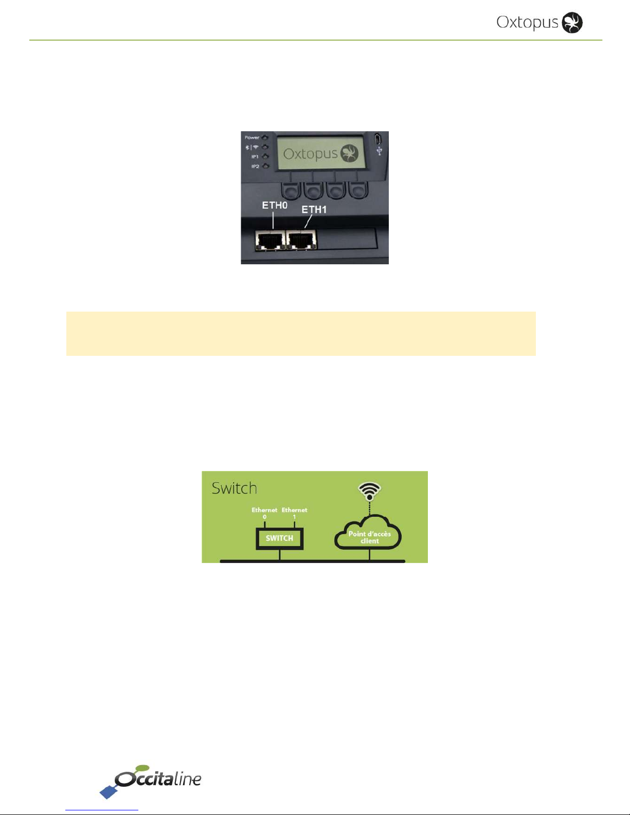
1.3 Ethernet connection
All references are equipped with two RJ45 connectors. Communication can be done
independently on both sides with network.
Figure 2
Ethernet Connectors Eth0 and Eth1
The two RJ45 Ethernet connectors are configured in factory as Ethernet switch.
The main connector is the left ETH0. The Computer must be primarily connected to this port.
In this configuration, the router has only one IP address for all its functions.
1.4 Wifi Connection – Ethernet
The Wifi option proposed in Oxtopus references allows access to Ethernet RJ45.
Figure 3
Architecture Ethernet IP
A computer can connect over WiFi Oxtopus to reach other Oxtopus or other equipment as the
LNS server.
If a DHCP server provides an IP address on Ethernet, the computer do not need a fixed IP
address, its Wi-Fi connection will assign a network address automatically.

Release EN 0.93 Page 8/53
User Manual
1.5 Automation protocols supported
The EIA-709.1 and Modbus protocols are supported on Oxtopus router and run on IP separately.
1.5.1 Router EIA-709.1
In Oxtopus routers, the EIA-709.1 protocol is available either on twisted pair or over IP. In order
to pass from one media to another, it is implemented in a router function. This is conforms to the
EIA-709.1 protocol and ensures the traffic filtering.
Figure 4
Architecture of Oxtopus router
To connect 2 media, a simple router is enough. To connect more than 2 medias a Virtual Media is
introduced into the router to follow the installation and operate procedures of the EIA-709.1
networks.
1.5.2 Router NAT Modbus
The Modbus protocol cannot be a router function. It was implemented a frame redirection by
changing the slave address. Hence the term NAT Router (Address Translation Router). Depending
on the number of EIA-485 Modbus port available on the reference, Modbus master address
requests on IP, the request will be redirected to the desired port with a new slave address.
Each EIA-485 port can only support 31 Modbus slaves. The Modbus address space is limited to
247 members. Within the maximum terms it is possible to send 31 * 4 = 124 Modbus slaves on
EIA-485.

Release EN 0.93 Page 9/53
User Manual
Configuration example:
Slave source
address
Port EIA-485 Slave destination
address
10 Port 3 1
11 Port 3 2
20 Port 4 1
21 Port 4 2
1.6 Other protocols supported
1.6.1 EIA-852 Device
This protocol is transparent for the installer and operator of the router. It is used for exchanges
between members of a Channel IP.
1.6.2 EIA-852 Config Server
It is the virtual administrator of a Channel IP. All nodes or routers members of this channel are
declared in a list ( "channel list") and may share data.
If a member is forgotten it cannot share with others.
The « Config Server » router must be declared in the channel list as member.
A router cannot belong on two channel lists member.
1.6.3 Web
An embedded Web server provides the router setup and provides a view of the general state of
the router. It is accessible via its IP address with a browser like Firefox, Chrome or Internet
Explorer. You can also access via WiFi with a tablet or smartphone. Web pages are automatically
resized according to your device.
The configuration pages are protected by password.
Login : « admin », Password: « oxpass »
1.6.4 Disk space embedded in FTP
A user disk space is available to store your files or documentation. This space is limited access via
FTP with login and password.
Login : « ftp », Password: « ftp ».

Release EN 0.93 Page 10/53
User Manual
2 Connecting and
Material
Release EN 0.93 Page 11/53
User Manual
2.1 Ethernet
The cables used should not exceed 90 meters. The left connector Eth0 must be privileged.
The default address is 192.168.1.254.
2.2 Wifi
The connection can support multiple devices. It can be enabled or disabled on the router with
buttons and the LCD display or on the Web page
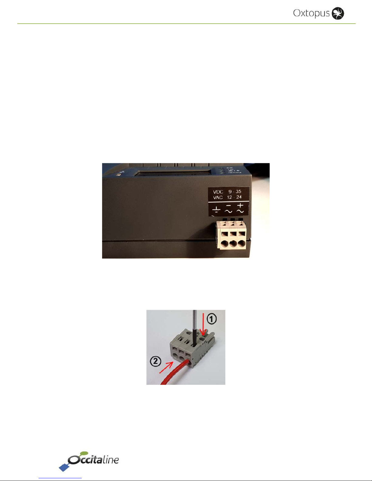
2.3 Power
The material feed may be made in DC voltage or AC voltage.
Figure 5
The rear power connector
The power connector is a clips connector. Wire are inserted using a screwdriver 2.5mm or a
suitable tool.
Figure 6
Insert wire in power connector
2.4 Wiring
According to the reference with 1, 2, 3 or 4 EIA-709 ports, ports are used, starting with the left.
Release EN 0.93 Page 12/53
User Manual
According to reference product 1, 2, 3 or 4 EIA-485 ports, the ports are used starting from left or
following EIA-709.
Reference Port 1 Port 2 Port 3 Port 4
Ox-1Lo-1Mo
TP/FT10
EIA-709.1
EIA-485
Modbus
Ox-1Lo-2Mo
TP/FT10
EIA-709.1
EIA-485
Modbus
EIA-485
Modbus
Ox-2Lo-1Mo
TP/FT10
EIA-709.1
TP/FT10
EIA-709.1
EIA-485
Modbus
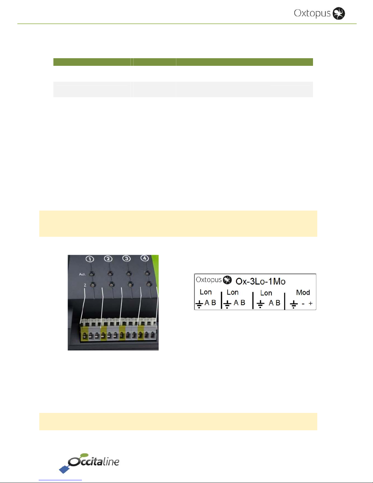
2.5 Wired network EIA-709.1 / EIA-485 Modbus
The EIA-709 protocol is not polarized; the front connectors are identified in groups by three, left
to right: Earth Net Net A and B.
Modbus over EIA-485 is polarized. Be careful, you must connect the + of all equipment on the
right terminal and the - pole on the left terminal.
When the devices are powered by different sources, the third connector must be connected to
the reference.
Figure 7
Stick network connector TP/FT10 and EIA-485
Figure 8
Wired connection TP/FT10 CEA_709.1
A polarity inversion does not damage device, but the communication does not works.

Release EN 0.93 Page 13/53
User Manual
2.6 LED signalization
2.6.1 Power LED
The POWER LED is ON in Green at the beginning of power on. A red color indicates a fault on the
router.
2.6.2 Wifi LED
For Oxtopus routers with wifi option, WIFI LED will be green to indicate that wifi is active; the red
color indicates that the wifi is inactive.
For routers that do not have wifi, this LED is off.
2.6.3 IP1/IP2 LED
IP LEDs indicates the status of each port and architecture
LED Ethernet architecture
LED IP1 ON IP Ports works in « switch » mode
LED IP2 ON Ports are configured in « double IP »
Regardless of the architecture, the color of the LED indicates the operation of the connection.
A green LED indicates that the Ethernet connection is working properly.
A red LED indicates that the Ethernet connection is not working. This may be due to the inability
to retrieve an IP address via DHCP for example.
Finally, an orange LED indicates that the Ethernet connection is working, but a fault has been
detected during startup. Services such as CNIP (LON 852) Config Server and Modbus do not work.
This may be due to, for example, significant time between the router startup and recovery of an
IP address via DHCP. In this case the DHCP worked but the address was acquired too late, the
services were launched without IP.
2.6.4 LED Activity (« Act. »)

Release EN 0.93 Page 14/53
User Manual
2.6.4.1 LON FT/TP-10
EIA 709 Port of Oxtopus router has a bicolor LED:
Behavior Description Comment
GREEN blinking Traffic Receiving or sending frame
GREEN blinking at 1HZ Port Not configured
RED blinking Errors on medium Lost frame due to:
- CRC Error
- Most important Traffic
2.6.4.2 Modbus RS485
A Modbus-RS485 port of Oxtopus router has a bicolor LED:
Behavior Description Comment
GREEN blinking Traffic Receiving or sending frame
RED blinking Errors on medium Lost frame due to:
- CRC Error
2.6.5 LED Z
It is used to view the state of the line impedance: fault if line break or termination not connected
et each ends.
LED in GREEN indicates that impedance is good.
LED in RED indicates that impedance is fault.
2.7 Screen
The Oxtopus Router has a LCD screen in front. When the router starts, the screen displays the
logo "Occitaline" and the name of the router.
Figure 9 : Home screen
The buttons below the display are used to navigate in the menu.
Release EN 0.93 Page 15/53
User Manual
Press one of the buttons to access the menu which indicates the router configuration and
bandwidth usage in real time to the ports LON FT / TP10.
Figure 10 : First page menu
Buttons below the arrows are used to select the port. Once selected, press the button under the
symbol "SP" (Service Pin) to send a service pin of the Neuron Chip of that port.
Whatever the selected port, the button under the symbol "GSP" allows you to send a service pin
of each external Neuron Chip on router.
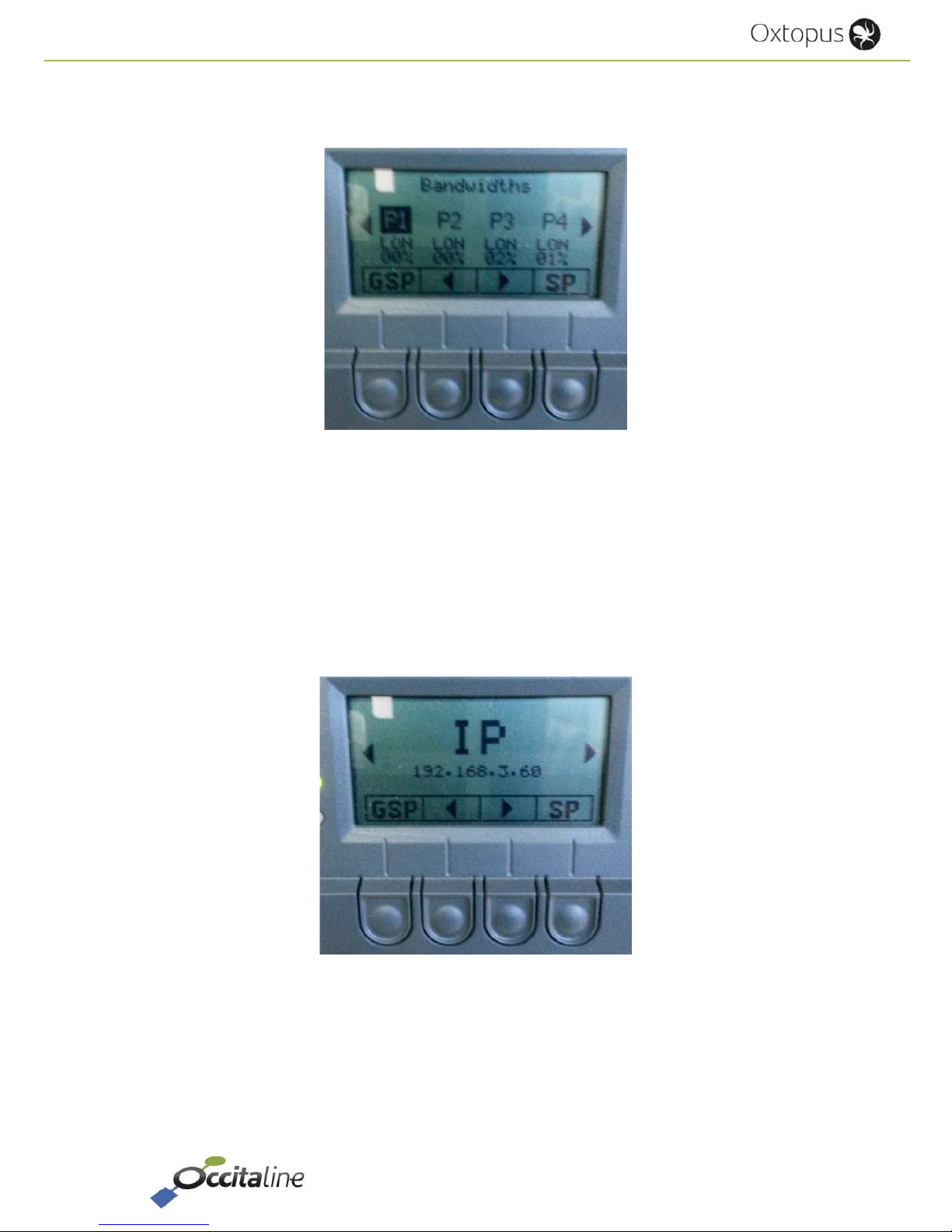
Finally, the page after Ports show you the IP address of the router.
Figure 11 : IP page

Release EN 0.93 Page 16/53
User Manual
3 Easy and fast setting
 Loading...