

Obvius AcquiSuite Ally 12, AcquiSuite Ally 48, AcquiSuite Ally User Manual
Revision C (11/18)
User’s Guide
AcquiSuite™
Ally 12 & 48
Advanced Multi-Circuit Meter
And
AcquiSuite Ally
Configuration Console
Software

AcquiSuite Ally 12 & 48 User Guide (Rev D)
ii | P a g e
User’s Guide: AcquiSuite™ Ally Power Meters ©2018 Obvius, Inc. All rights reserved.
This manual may not be reproduced or distributed without written permission from Obvius.
AcquiSuite™ is a trademark of Obvius, Inc.
Windows®, Windows® 7, Windows® 8, and Windows® 10, are registered trademarks of Microsoft
Corporation.

AcquiSuite Ally 12 & 48 User Guide (Rev D)
iii | P a g e
TABLE OF CONTENTS
Table of Contents ................................................................................................................ iii
Introduction ......................................................................................................................... 6
Unpacking the Unit .......................................................................................................................... 6
AcquiSuite™ Ally Anatomy ............................................................................................................... 7
AcquiSuite™ Ally Meter Safety Summary and Specifications .......................................................... 9
Symbols on Equipment .................................................................................................................... 9
Symbols in Documentation .............................................................................................................. 9
Meter SAFETY .................................................................................................................... 11
Building Service Safety Requirements (Load Center, etc.) ............................................................ 11
Meter Installation Safety Requirements ........................................................................................ 11
Planning For Field Installation ............................................................................................ 12
Project Manager Aspects ............................................................................................................... 12
Configuration & Data Viewing Options ................................................................................... 12
Information Access by Interface Type ..................................................................................... 13
Meter Configuration Overview ...................................................................................................... 14
Meter Installation Overview ......................................................................................................... 14
Verification & Communication Overview ...................................................................................... 15
RTU Programming and Scripting Overview .................................................................................... 15
Meter Configuration - Details ............................................................................................. 16
Install the Software ........................................................................................................................ 16
CONNECTION & CONFIGURATION OPTIONS USING OBVIUS ALLY CONFIGURATION CONSOLE ... 16
Recommended Connection via USB AB Cable ......................................................................... 16
Ethernet Network Connection ................................................................................................ 17
DYNAMIC HOST CONFIGURATION PROTOCOL (DHCP): .................................................... 17
DIRECT: .................................................................................................................................... 18
NETWORK SCAN ...................................................................................................................... 19
LAUNCH CONFIGURATOR ........................................................................................................ 19
Obvius Ally Configuration Console Software Overview ................................................................. 20
Obvius Ally Configuration Console Documentation ...................................................................... 21
Configuring Electrical Components using Obvius Ally Configuration Console .............................. 22
Configuring Communications using Obvius Ally Configuration Console ....................................... 23
CONFIGURING ALARMS IN OBVIUS ALLY CONFIGURATION CONSOLE .......................................... 24
Configuration Input Methods .................................................................................................. 24
Nominal Values ........................................................................................................................ 24
Absolute Values ....................................................................................................................... 24
Setting the Real Time Clock ..................................................................................................... 25
Real Time Clock Power Source .......................................................................................... 25
Retrieving Interval Data ........................................................................................................... 26
Web Application Overview ............................................................................................................ 27

AcquiSuite Ally 12 & 48 User Guide (Rev D)
iv | P a g e
Connect to Web Application using USB .................................................................................. 27
Connect to Web Application using Ethernet ........................................................................... 27
Authentication ......................................................................................................................... 27
Meter Installation - Details ................................................................................................ 28
Meter Mounting Configurations .................................................................................................... 28
Installation Sequence .............................................................................................................. 29
Connecting Voltage ................................................................................................................. 31
Wiring the AcquiSuite™ Ally Meter in a 3-wire, Split ɸ Service Panel ........................................... 32
Wiring the AcquiSuite™ Ally Meter in a 4-wire, 3 ɸ Service Panel ................................................ 33
Current Transformer Basics ........................................................................................................... 34
Wiring the CTs to the AcquiSuite™ Ally Meter ............................................................................... 35
Communication & Verification - Details ............................................................................. 36
Physical Connections on an RS-485 Multidrop Network ............................................................... 36
Communication Verification .......................................................................................................... 37
Obvius Ally Configuration Console / Web Application ............................................................ 37
Physical Interface Verification ....................................................................................................... 38
Serial Setup Verification .......................................................................................................... 38
LAN Ethernet Network Verification ......................................................................................... 38
DHCP ........................................................................................................................................ 38
STATIC IP .................................................................................................................................. 38
Protocol Verification ...................................................................................................................... 39
Modbus Settings ............................................................................................................................ 39
Modbus RTU Settings .............................................................................................................. 39
Modbus TCP Settings ............................................................................................................... 39
BACnet Settings .............................................................................................................................. 39
BACnet MSTP ........................................................................................................................... 39
BACnet IP ................................................................................................................................. 39
Pulse Inputs .................................................................................................................................... 40
ALARM (SPDT) ................................................................................................................................ 41
12 Volt Auxiliary Power .................................................................................................................. 41
Access Restriction Limitations ................................................................................................. 42
Security PIN Protection ........................................................................................................... 42
USING THE PERMISSION REGISTERS........................................................................................ 42
Read Only Permission Register ................................................................................................ 43
Read/Write Permission Register ............................................................................................. 43
READING PINS OVER MODUS OR BACNET .............................................................................. 43
Obvius Ally Configuration Console UNRESTRICTED ACCESS ................................................... 43
Verification of CT Installation ........................................................................................................ 44
Installation Phase Verification ................................................................................................. 44
Phase Checking By Phasor Plot ................................................................................................ 45
CT Orientation Check ..................................................................................................................... 46

AcquiSuite Ally 12 & 48 User Guide (Rev D)
v | P a g e
Power Factor Convention .............................................................................................................. 47
Total Harmonic Distortion ............................................................................................................. 47
Pre-Processing Aids ........................................................................................................................ 48
Snap Thresholds ...................................................................................................................... 48
Multipliers ............................................................................................................................... 48
CT Phase Shifts ........................................................................................................................ 48
Demand ................................................................................................................................... 48
RTU Programming and Scripting - Details ........................................................................... 49
Register Organization ..................................................................................................................... 49
Element vs System Scope ........................................................................................................ 49
Configuring Element and Channel Register for Service Types ................................................ 50
Configuring System Registers .................................................................................................. 51
Modbus Protocol Commands ........................................................................................................ 52
BACnet ........................................................................................................................................... 53
BACnet Structured View .......................................................................................................... 53
Appendix A—ACQUISUITE™ Ally LCD Menu Navigation ..................................................... 55
MENU NAVIGATION ....................................................................................................................... 56
COMMUNICATION NAVIGATION ................................................................................................... 57
Appendix B—Enclosure Dimensions ................................................................................... 58
Appendix C—Mounting Templates ..................................................................................... 59
Appendix D—ACQUISUITE™ Ally Technical Specifications .................................................. 61

AcquiSuite Ally 12 & 48 User Guide (Rev D)
6 | P a g e
INTRODUCTION
There are two meters in the AcquiSuite™ Series: the AcquiSuite™ Ally 12 & Ally 48. These meters monitor
the voltage, current, power, energy, and many other electrical parameters on single and three-phase
electrical systems. A AcquiSuite™ Ally meter uses direct connections to each phase of the voltage and
current transformers to monitor each phase of the current. Information on energy use, demand, power
factor, line frequency, and more are derived from these voltage and current inputs.
The AcquiSuite Ally is the perfect companion to the Obvius data acquisition product line. The Ally 48’s
versatile power metering functionality continues the Obvius mission of lowering the total cost of collecting
data by reducing install complexity, and increasing flexibility. The plug-and-play integration ensures the
hundreds of data points are immediately captured and made available for countless applications.
The AcquiSuite™ Ally meter communication interfaces include Ethernet (LAN), RS-485 serial, BACnet
MS/TP and Modbus RTU are the two communication protocols that operate over an RS-485 serial network
and BACnet IP and Modbus TCP are supported over Ethernet. A USB port is also provided as the preferred
connection for on-site configuration and can be run concurrently with an RTU.
Unpacking the Unit
The AcquiSuite™ Ally can be ordered with optional product features which are identifiable on the part
number label.
AcquiSuite™ Ally Part Numbering Scheme
AMC48-ED 48 Input Meter Enclosure with display
AMC48-EN 48 Input Enclosure without display
AMC48-MD 48 Input Mounting Plate with display
AMC48-MN 48 Input Mounting Plate without display
AMC12-ED 12 Input Enclosure with display
AMC12-EN 12 Input Enclosure without display
AMC12-MD 12 Input Mounting Plate with display
AMC12-MN 12 Input Mounting Plate without display
Each AcquiSuite™ Ally meter shipment also includes the following items:
▪ Meter with Options Installed – Serial Number, MAC ID, and FCC ID indicated on side label.
▪ Pluggable Connectors (2 voltage, 50 three-position terminals, 3 two-position terminals)
o AMC48 (2 voltage, 50 three-position terminals, 3 two-position terminals)
o AMC12 (1 voltage, 14 three-position terminals, 5 two-position terminals)
▪ Thumb drive containing Obvius Ally Configuration Console Software, Register List, Manual,
Tutorial Videos
▪ Certificate of Calibration (COC) for each unit

AcquiSuite Ally 12 & 48 User Guide (Rev D)
7 | P a g e
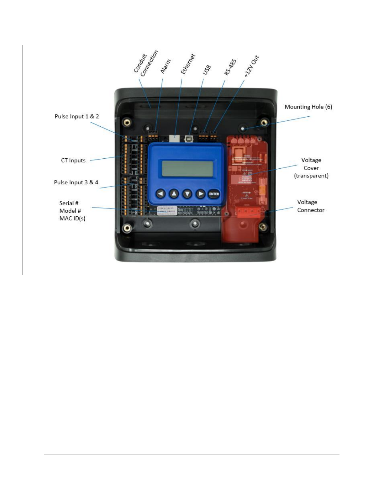
AcquiSuite™ Ally Anatomy
All user connections are made on the circuit board. Connectors are identified by function and include
polarity markers.
Element ID
Element ID
LCD Display
Navigation
Buttons
Plate
Ground
Serial #
Model #
MAC ID(s)
Voltage
Input 1
Voltage
Input 2
AMC48 mounting plate version shown
AcquiSuite Ally 12 & 48 User Guide (Rev D)
8 | P a g e
AMC12 enclosure version with display shown (cover removed)
AcquiSuite Ally 12 & 48 User Guide (Rev D)
9 | P a g e
AcquiSuite™ Ally Meter Safety Summary and Specifications
This general safety information is to
be used by both the Logger operator
and servicing personnel. Obvius, Inc.
assumes no liability for user’s failure
to comply with these safety
guidelines.
AMC12-B-y-z, -P-y-z
AMC48-B-y-z, -P-y-z
AMC12-C-y-z
AMC48-C-y-z
The AcquiSuite™ Family conform to
the following:
AcquiSuite™ Ally 12 & Ally 48:
Conforms to UL Std 61010-1, 3rd
Edition
Certified to CSA Std C22.2 No.
61010-1, 3rd Edition
AcquiSuite™ Ally devices need to be installed in a user-supplied UL Listed/ uR Recognized enclosure in order to comply
with NEC and local electrical codes.
The AcquiSuite™ Ally is an Over-Voltage Category III device. Use approved protection when operating the device.
CAUTION: THIS METER MAY CONTAIN LIFE THREATENING VOLTAGES. QUALIFIED PERSONNEL MUST DISCONNECT
ALL HIGH VOLTAGE WIRING BEFORE SERVICING THE METER WITH THE HIGH VOLTAGE TOUCH SAFE
COVER REMOVED.
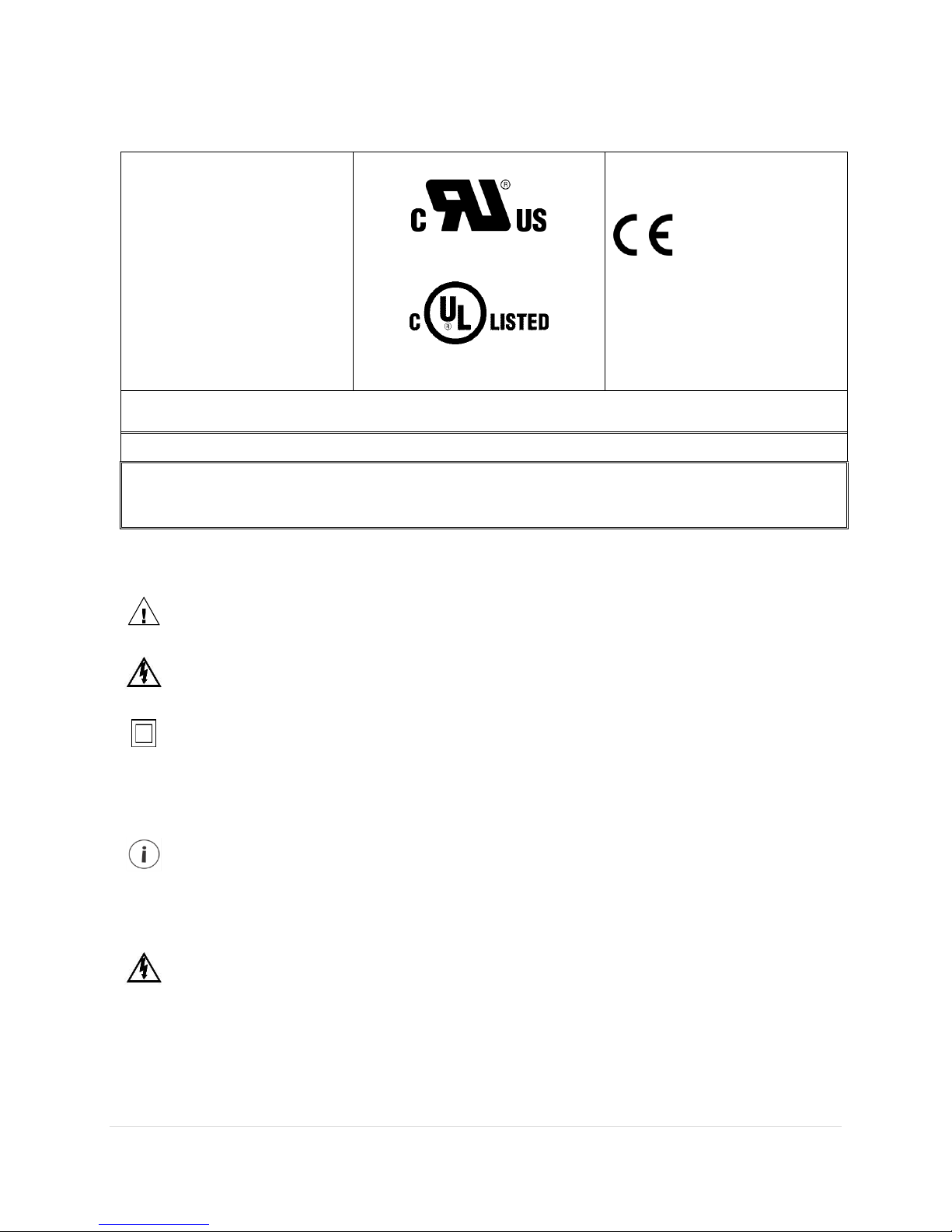
Symbols on Equipment
Denotes caution. See manual for a description of the meanings.
DENOTES HIGH VOLTAGE. RISK OF ELECTRICAL SHOCK. LIFE THREATENING VOLTAGES MAY BE PRESENT.
QUALIFIED PERSONNEL ONLY.
Equipment protected throughout by double insulation (IEC 536 Class II).
Symbols in Documentation
Contains additional information pertinent to current subject
DO NOT EXCEED 346V Line to Neutral or 600 volts Line to Line. This meter is equipped to
monitor loads up to 346V L-N. Exceeding this voltage will cause damage to the meter and
danger to the user. Always use a Potential Transformer (PT) for voltages in excess of 346V
L-N or 600 volts line to line. The AcquiSuite™ Ally is a 600 Volt Over Voltage Category III
device.

AcquiSuite Ally 12 & 48 User Guide (Rev D)
10 | P a g e
MAINTENANCE
There is no required maintenance with the AcquiSuite™ Ally 12 & Ally 48 meter.
Abide by the following items:
• Cleaning: No cleaning agents, including water, shall be used on the AcquiSuite™ Ally 12 & Ally 48 meter.
• No accessories are approved for use with the AcquiSuite™ Ally 12 & Ally 48 meter, other than those
specified in the Obvius product literature and price sheets.
• If the meter appears damaged or defective, first disconnect all power to the meter. Then call or email
technical support for assistance.
Obvius
20497 SW Teton Avenue, Tualatin, OR 97062
(503) 601-2099
(866) 204-8134 (USA Only)

AcquiSuite Ally 12 & 48 User Guide (Rev D)
11 | P a g e
METER SAFETY
Building Service Safety Requirements (Load Center, etc.)
• Equipment intended for use with field-installed current transformers that could be installed in
panel boards or switchgears shall observe the following:
• Always open or disconnect circuit from power-distribution system (or service) of building before
installing or servicing current transformers.
• A circuit breaker used as a disconnect must meet the requirements of IEC 60947-1 and IEC
60947-3 (Clause 6.11.4.2)
• Current transformers may not be installed in equipment where they exceed 75 percent of the
wiring space of any cross-sectional area within the equipment.
• Current transformers may not be installed in an area where they block ventilation openings.
• Current transformers may not be installed in an area of breaker arc venting.
• Not suitable for Class 2 wiring method nor intended for connection to Class 2 equipment.
• Secure current transformer and route conductors so that they do not directly contact live
terminals or bus.
• CTs shall be listed to UL2808
Meter Installation Safety Requirements
• AcquiSuite™ Ally meters must be installed in accordance with local electrical codes.
• Use copper conductors only.
• Connection to the mains terminals shall be made with 14 AWG minimum wire gauge.
• External secondary inputs and outputs should be connected to devices meeting the
requirements of IEC 60950
• The following additional requirements apply for Recognized board versions of the AcquiSuite™
Ally meter
• For use only with Listed Energy-monitoring Current Transformers
• Associated leads of the current transformers shall be maintained within the same overall
enclosure.
• Unless the current transformers and its leads have been evaluated for REINFORCED
INSULATION, the leads must be segregated or insulated from different circuits.
• The current transformers are intended for installation within the same enclosure as the
equipment. These may not be installed within switchgears and panel boards” or similar.

AcquiSuite Ally 12 & 48 User Guide (Rev D)
12 | P a g e
PLANNING FOR FIELD INSTALLATION
Project Manager Aspects
Meter installation often includes coordination between individuals or groups of people with different
responsibilities. Spend a few minutes considering who will be executing each portion of the installation
and what tools are needed at each stage. Things to consider include determining how to communicate
with the meter, setting address configuration, installing Obvius Ally Configuration Console, access to PIN
number, etc. The more tasks completed before installation, the fewer tasks required in the field. The
following section gives an overview of these activities followed by details in the next section.
CONFIGURATION & DATA VIEWING OPTIONS
The AcquiSuite™ Ally meter has multiple methods for configuration and data viewing. The most powerful
interface is provided with a PC, Laptop or Tablet running Windows and is encouraged for complex
installations. The Ally Configuration Console software is required for configuring advanced functions like
alarms. The second interface is intended for smart phones or tablets that can connect over USB, Ethernet,
or Wi-Fi. The third interface (LCD) is intended for intermittent end user observation and is restricted in
capability. Utilizing the AcquiSuite DAS interface can also be used for configuration, if communication
settings are already established. The feature set of each interface is summarized next.

AcquiSuite Ally 12 & 48 User Guide (Rev D)
13 | P a g e
INFORMATION ACCESS BY INTERFACE TYPE
Interface Options
Device
PC or Laptop Running
Obvius Ally Configuration
Console
Smart Device or Tablet via
WebPage
LCD on Meter
(if equipped)
RTU
(Host System)
Modbus /BACnet
When
Used
Meter Setup
Field Visit
Field Visit
End User
Building
System
Real Time Values
All Meter Parameters
Waveform Capture
Harmonic Analysis
All Element View
Phasor Plot
Alarms
All Meter Parameters
Single Element View
Voltage
Current
VA
VAR
kWh
Single Element View
All Meter Parameters
Configuration
Entire Meter
Visual Guides
Copy / Paste
Entire Meter
(except alarms)
Text Based
Communications Only
Entire Meter
Register Based
Security PINs
Enforced
Factory Support – Level 3
Read Only – Level 1*
Read / Write – Level 2*
Read Only – Level 1*
Read / Write Level 2*
(limited to
communication)
Factory Support –
Level 3
* If PINs are configured
AcquiSuite Ally 12 & 48 User Guide (Rev D)
14 | P a g e
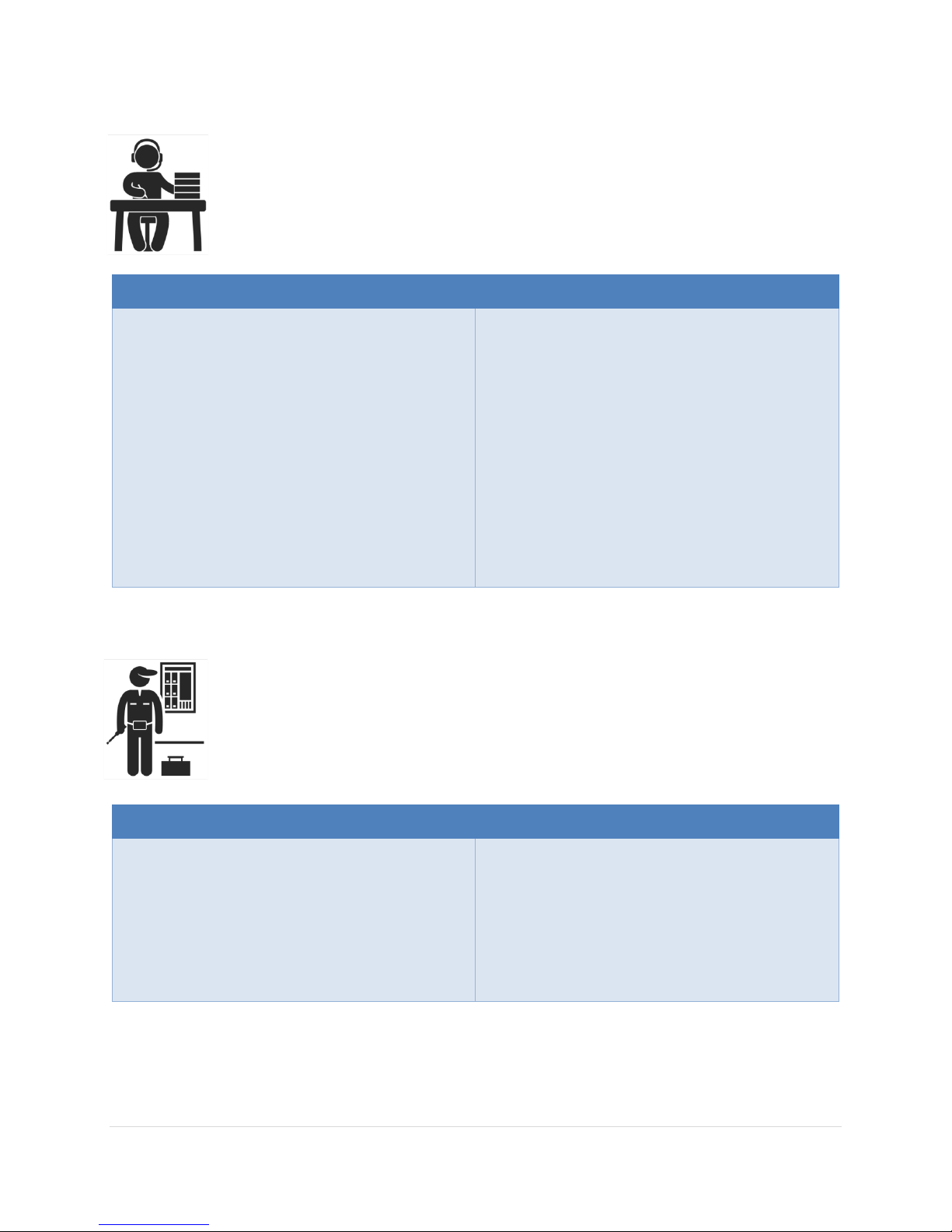
Meter Configuration Overview
▪ Work performed ahead of the installation saves time in the field and results in fewer
mistakes!
Tools
Typical Work
• Desktop or Laptop PC
• USB Type AB Cable (preferred) or
Ethernet & USB wall charger (> 500 mA)
• Thumb Drive (Obvius Ally Configuration
Console Installer) or
access to Obvius FTP site. (qualified Obvius
personnel only)
• Electrical Schematics of project
• Installation of Obvius Ally Configuration
Console Software
• Connect USB/Ethernet cable from PC to
meter
• Establish communication with meter
• Firmware update (if desired)
• Configure software for anticipated meter
setup
• Field wiring documentation
• Set Alarms
• Set Security PINs
Meter Installation Overview
▪ Performed by licensed electrician.
Tools
Typical Work
• Mounting hardware (customer supplied)
• Wiring & supplies, labels, wire ties
• Tablet, Smart Device, or
Laptop PC
• Multi Meter, Current Clamp
• Camera
• Mechanical mounting
• Electrical installation
• Install voltage cover
• Apply power to meter
• Confirm basic operation of meter
AcquiSuite Ally 12 & 48 User Guide (Rev D)
15 | P a g e
Verification & Communication Overview
▪ Can be modified with power applied to the meter.
Tools
Typical Work
• Tablet, Smart Device (Web Page Based),
or
Laptop PC (Obvius Ally Configuration
Console Software)
• On site troubleshooting
• Multi Meter, Current Clamp
• Camera
• Locate the power meter
• Confirm RTU device
• Add wire terminations (if required)
• Confirm meter communication settings
• Meter health metrics (check for setup
errors)
• Analytics (Obvius Ally Configuration
Console)
• Correct instrumentation
• Set Alarms
• Set security PINs
• Checklist
RTU Programming and Scripting Overview
Tools
Typical Work
• Laptop PC (Remote Access to RTU)
• Remote troubleshooting
• Register List
• Confirm meter communication settings
• Confirm communication protocols
• Exercise remote connectivity
• Run configuration scripting
• Set Alarms
• Set security PINs
• Confirm data integrity
AcquiSuite Ally 12 & 48 User Guide (Rev D)
16 | P a g e
METER CONFIGURATION - DETAILS
This section is written to support setting up the AcquiSuite™ Ally meter in an office
environment and configuring the power meter for a pre-determined configuration. In
many cases the setup is standardized for an organization or project. In other cases, the
setup can be documented and forwarded to an electrician as a wiring schedule. The setup
can also be performed on site and reflect “as built” configurations.
• The Ally meter cannot be configured using Obvius Ally Configuration Console over a serial
port. RS-485 serial network configurations must be pre-configured or use Modbus / BACnet
hosts.
• This section describes the use of the Obvius Ally Configuration Console Windows Application.
If this interface cannot be used, refer to the section on using the simplified web browser
interface. The web browser can be accessed from the USB port to support Mac users.
Install the Software
Insert the Obvius Ally Configuration Console thumb drive into the computer or download from the Obvius
FTP site. (qualified Obvius personnel only)
The installer should start automatically. If it does not, browse the thumb drive and locate the
AllyConfigurationConsoleInstaller.exe program. Start the installer by double-clicking on it, and follow the
installer instructions.
CONNECTION & CONFIGURATION OPTIONS USING OBVIUS ALLY
CONFIGURATION CONSOLE
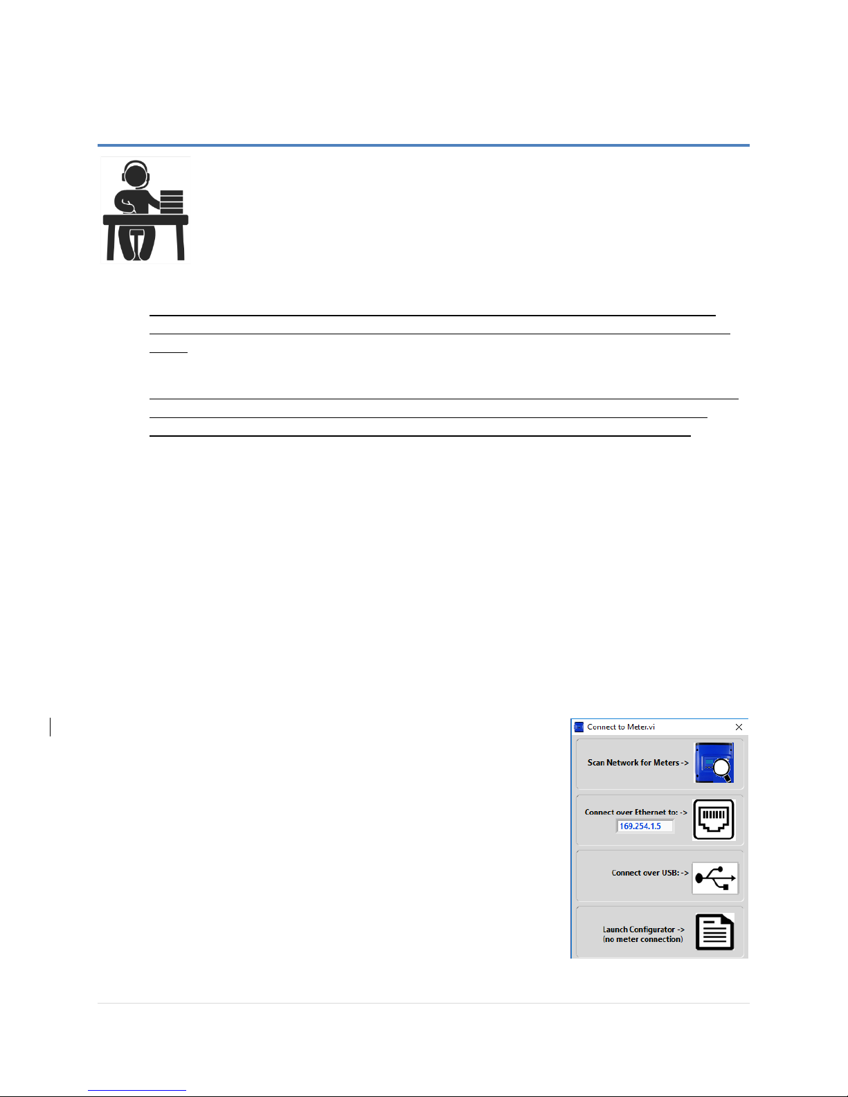
When the Obvius Ally Configuration Console application is launched, it
will prompt the user to select one of four connectivity options.
• Connect over USB (recommended)
• Connect over Ethernet
• Scan Network
• Launch Configurator (no meter connection available)
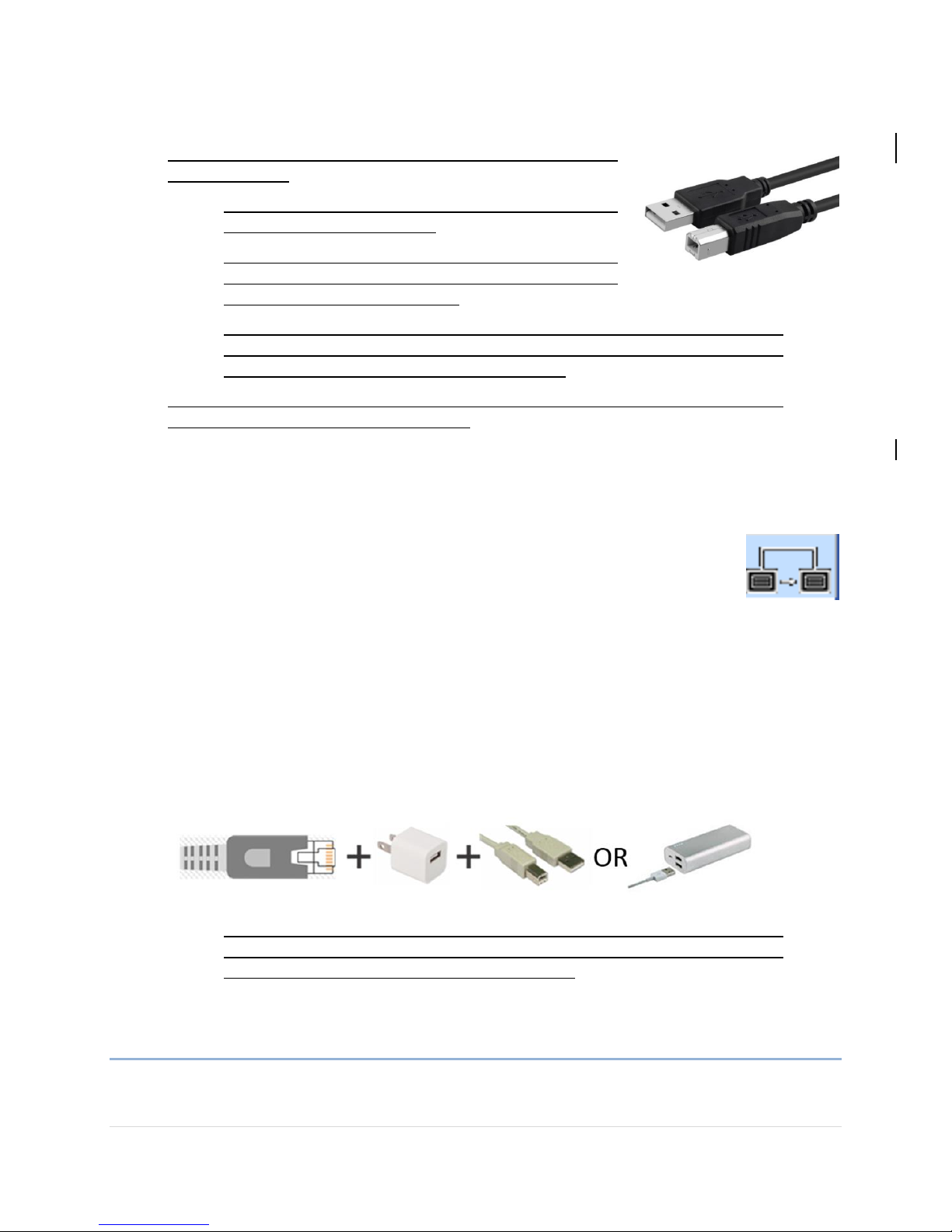
RECOMMENDED CONNECTION VIA USB AB CABLE
The preferred method for configuring the AcquiSuite™ Ally meter from a
locally connected computer is through the USB interface which provides
power to the meter as well as communications.
AcquiSuite Ally 12 & 48 User Guide (Rev D)
17 | P a g e
1) Connect the Ally meter to a USB port of your computer using a
USB A to B cable.
a. If equipped, the LCD display is the most visable
indication of a running meter.
b. For meters without a display, a green flashing LED on
the circuit board indicates that the AcquiSuite Ally
meter has booted and is running.
c. The meter will draw 450mA from the USB port which could potentially overload
“out of spec” USB hosts. If the meter fails to power from USB, an alternate
configuration to power the meter must be used.
2) Launch the Obvius Ally Configuration Console application and press the “CONNECT
OVER USB” button on the pop-up window.
The meter should now be communicating. Obvius Ally Configuration Console offers visual guides and
context help to facilitate meter configuration. Please read the Obvius Ally Configuration Console overview
section (below) or watch the tutorial videos for additional information on configuring the meter. By
default, Ally12 & Ally 48 meters are configured for DNS Ethernet addressing. A very common configuration
sequence is using USB to configure a meter for Ethernet communications at a static IP
address and then switching from USB over to Ethernet to locate it. This is facilitated in
Obvius Ally Configuration Console by pressing the “Refresh Connectivity” icon located in
the upper right hand corner.
ETHERNET NETWORK CONNECTION
Configuring the Ally meter over Ethernet requires that the meter be powered from an alternate
connection. The PSHD does not support Power Over Ethernet (POE). If the meter is already installed
within the buildings electrical network, closing the AC breaker (or approved disconnect) will turn on the
meter through the meter’s internal power supply. In the rare case that a computer’s USB port cannot
provide 500mA of current, an AC / USB charger or a USB battery can be used as a power source while
using Ethernet for communications. .
• Both the “Network Scan” and “Connect Over Ethernet to IP …” options require
that a valid network connection exists between the AcquiSuite Ally meter and
configuration PC. This is a common startup issue.
DYNAMIC HOST CONFIGURATION PROTOCOL (DHCP):
Ally meters are shipped in DHCP mode to prevent IP conflicts with other equipment. The meter is
expecting to receive an IP address from a DHCP service provided by a router, Layer 3 switch, or a server
AcquiSuite Ally 12 & 48 User Guide (Rev D)
18 | P a g e
providing DHCP service. Under this configuration, as long as the AcquiSuite Ally meter and the host PC
are requesting an IP address from the same DHCP service provider, they will be able to communicate.
Upon powering up, the AcquiSuite Ally meter will indicate the IP address on the LCD display (if
equipped) or can be found using the Network Scan function.
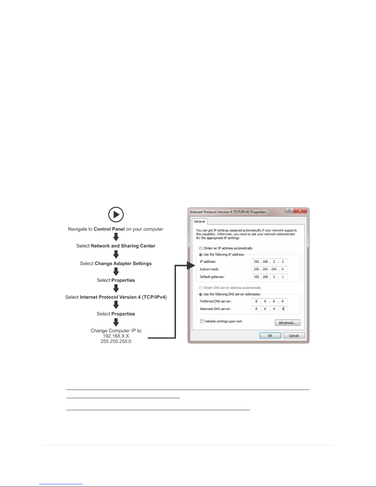
DIRECT:
When a PC is directly connected to an Ally meter via an ethernet cable, no DHCP service exists. This
configuration can be made to work, but requires changes to either the meter communication settings or
the PC network configuration.
LCD Display
For units equipped with an LCD display navigate to
Communications Ethernet Settings DHCP OFF
Change the IP address in the meter to match the subnet of your PC’s IP address, making the
meter IP unique, or note the current address on the meter and prepare to configure your PC’s IP
settings as shown below.
Once the PC and Ally meter are set to communicate on the same IP subnet:
1) Launch the Obvius Ally Configuration Console application and enter the IP address of
the meter (shown as the factory default)
2) Press the “Connect over Ethernet” button on the pop up window.
3) The meter should now be communicating. Obvius Ally Configuration Console is an intuitive
application; read the Obvius Ally Configuration Console overview section below.
AcquiSuite Ally 12 & 48 User Guide (Rev D)
19 | P a g e
No LCD Display
An AcquiSuite Ally meter without a display can only communicate directly with a PC over
ethernet if the IP address of the meter is set to static. Setting the IP address must be done
ahead of time using another interface (such as USB or serial).
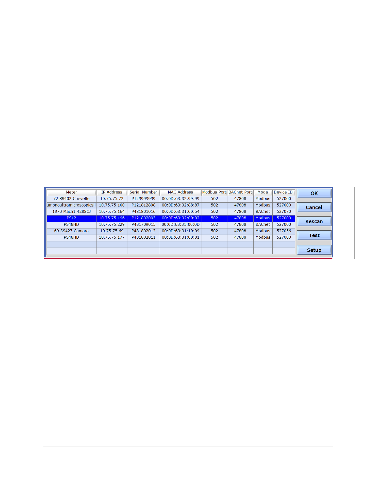
NETWORK SCAN
Network Scan is a feature for monitoring previously installed and configured AcquiSuite Ally meters over
an Ethernet network. Network Scan will broadcast a UDP discovery packet on the same network as the
PC running the Obvius Ally Configuration Console application. Normally this will be performed on a
corporate network running DHCP. Any PowerScout HD meter that responds will be displayed in a table
that includes the system description register, IP address, serial number, and communication
configuration.
Highlight the desired meter and select OK, Test or Setup. Note that the effectiveness of this technique is
highly dependent on the configuration of the PC running Obvius Ally Configuration Console (which may
have more than one network card) and the network configuration. Rescans can be used to make
multiple attempts to locate a particular meter on busy networks (UDP has no built-in retry provisions).
LAUNCH CONFIGURATOR
The final option in the Obvius Ally Configuration Console Connect to Meter pop-up window is “Launch
Configurator”. This option allows for the creation of a meter setup or alarm table for future use without
connecting to a meter. After prompting the user for a meter model (shown below), Obvius Ally
Configuration Console launches under a mode with restricted functionality. This mode operates on files
only.
 Loading...