

Page 1

Weather Station
Obvius, LLC
Installation and Operation Manual
Model A89WS
(3rd generation, systems manufactured after July 2010)
Date Jan 18, 2011
Page 1 Draft Copy A89WS Weather Station (gen 3)
Page 2

Copyright Information
Copyright © 2007 - 2010 by Obvius
Obvius and AcquiSuite are trademarks of Obvius Holdings LLc
Other brand and product names are trademarks or registered trademarks of their respective holders.
U.S. Government Restricted Rights: Use, duplication or disclosure by the Government is subject to restrictions set forth in subparagraph (a) through (d)
of the Commercial Computer Restricted Rights clause at FAR 52.227-19 when applicable, or subparagraph (c) (1) (ii) of the Rights in Technical Data and
Computer Software clause at DFARS 252.227-7013, and in similar clauses in the NASA FAR Supplement.
Limited Warranty
OBVIUS IS PROVIDING THIS WARRANTY IN LIEU OF ALL OTHER EXPRESS OR IMPLIED WARRANTIES, INCLUDING ANY WARRANTY
OF MERCHANTABILITY OR FITNESS FOR A PARTICULAR PURPOSE. THIS WARRANTY IS BUYER'S EXCLUSIVE REMEDY FOR ALL
CLAIMS AGAINST OBVIUS. OBVIUS SHALL NOT BE LIABLE FOR ANY CONSEQUENTIAL OR INCIDENTAL DAMAGES. OBVIUS'S TOTAL
LIABILITY FOR ALL CLAIMS SHALL BE LIMITED TO THE PRICE PAID FOR ITS PRODUCT.
Obvius promises buyer that any standard product manufactured by Obvius shall be free from all material defects in design, material, or manufacturing for
a period of 2 years from the manufacture date; provided, however, that the warranty shall not extend to ordinary wear and tear or to normally replaceable
components (e.g., batteries). During the warranty period, Obvius may repair or replace (in its sole discretion) any product suffering from a warranty defect
and returned freight prepaid by buyer, with no charge to buyer for any warranty repair or replacement. The warranty shall remain in full force and effect
for such 2 year period, provided that the product: (1) was installed, operated, and maintained properly; (2) has not been abused or misused; (3) has not
been repaired, altered, or modified outside of Obvius's authorized facilities; (4) has not been sold subject to other warranty terms specified at the time of
sale; and (5) is still owned by the original purchaser. This warranty provides specific legal rights that may be varied by state law. Obvius's products are
not designed for life or safety applications.
Product Application Limitation
Obvius products are not intended for use in critical applications such as nuclear facilities, human implantable devices or life support. Obvius is not liable,
in whole or in part, for any claims or damages arising from such uses.
Obvius strongly believes in continuous improvement, therefore we must reserve the right to change specifications and product offerings without notice.
Where possible, we will substitute products with equivalent functionality when necessary.
DANGER
Hazard of Electric Shock, Explosion or Arc Flash
● Follow safe electrical work practices. See NFPA 70E in the USA, or applicable local codes.
● This equipment must only be installed and serviced by qualified electrical personnel.
● Read, understand and follow the instructions before installing this product.
● Turn off all power supplying equipment before working on or inside the equipment. Use properly rated voltage sensing device to
confirm power is off. DO NOT DEPEND ON THIS PRODUCT FOR VOLTAGE INDICATION
● Only install this product on insulated conductors.
Failure to follow these instructions will result in death or serious injury.
NOTICE
● This product is not intended for life safety applications.
● Do not install this product in hazardous or classified locations.
● The installer is responsible for conformance to all applicable codes.
● Mount this product inside a suitable fire and electrical enclosure.
FCC Part 15 Information
Note: This equipment has been tested by the manufacturer and found to comply with the limits of a class A digital device, pursuant to part
15 of the FCC rules. These limits are designed to provide reasonable protection against interference when the equipment is operated in a
commercial environment. This equipment generates, uses, and can radiate radio frequency energy and, if not installed and used in
accordance with the instruction manual, may cause harmful interference to radio communications. Operation of this equipment in a
residential area is likely to cause harmful interference in which case the user will be required to correct the interference at his own expense.
Modifications of this product without the express authorization of Obvius nullify this statement.
Obvius
3300 NW 211th Terrace
Hillsboro, OR 97124
ph: 503-601-2099
www.obvius.com
Page 2 Draft Copy A89WS Weather Station (gen 3)
Page 3

Table of Contents
Overview....................................................................................................................................................................................................... 4
Installation Checklist..................................................................................................................................................................................... 4
Markings and Symbols.................................................................................................................................................................................. 4
Hardware Overview....................................................................................................................................................................................... 5
weather station Package Kits ..................................................................................................................................................................5
List of sub-assemblies.............................................................................................................................................................................. 6
Features and Specifications..................................................................................................................................................................... 7
Hardware Installation..................................................................................................................................................................................... 8
Overview................................................................................................................................................................................................. 8
A89WS-MK1: weather station Mounting kit........................................................................................................................................... 9
YWX0482: weather station Control Box...............................................................................................................................................10
YWX0483: weather station Control Box...............................................................................................................................................12
A89WS-AN1, A89WS-AN2: Anemometer kit......................................................................................................................................14
A89WS-PY1: Pyranometer kit............................................................................................................................................................... 15
A89WS-MP1: PV Mounting Bracket – Pyranometer (Optional).........................................................................................................16
A89WS-TC1, A89WS-TC2: Cell Temperature Kit...............................................................................................................................17
A89WS-TH1: Air Temperature and Humidity Probe.............................................................................................................................18
A89WS-TO1: Air Temperature Probe................................................................................................................................................... 18
Software setup and configuration.................................................................................................................................................................19
Modbus Configuration ..........................................................................................................................................................................19
Modbus Address and Dipswitch Configuration.....................................................................................................................................19
Setup and testing with Obvius Config Console (OCC) (optional).........................................................................................................20
Setup with Obvius AcquiSuite............................................................................................................................................................... 21
Channel 1: A89WS-TH1, TO1: Air Temperature Probe.................................................................................................................. 21
Channel 2: A89WS-TH1: Air Humidity Probe................................................................................................................................ 22
Channel 3: A89WS-PY1: Pyranometer...........................................................................................................................................22
Channel 4: A89WS-TC1,TC2: Cell Temperature............................................................................................................................ 23
Channel 5: A89WS-AN1,AN2: Anemometer / wind speed............................................................................................................. 23
Channel 6: A89WS-AN1,AN2: Anemometer / wind direction........................................................................................................ 24
Channel 7, Channel 8...................................................................................................................................................................... 24
Setup with 3rd party Modbus master..................................................................................................................................................... 25
Recommended Maintenance of third party devices...................................................................................................................................... 25
Page 3 Draft Copy A89WS Weather Station (gen 3)
Page 4

Overview
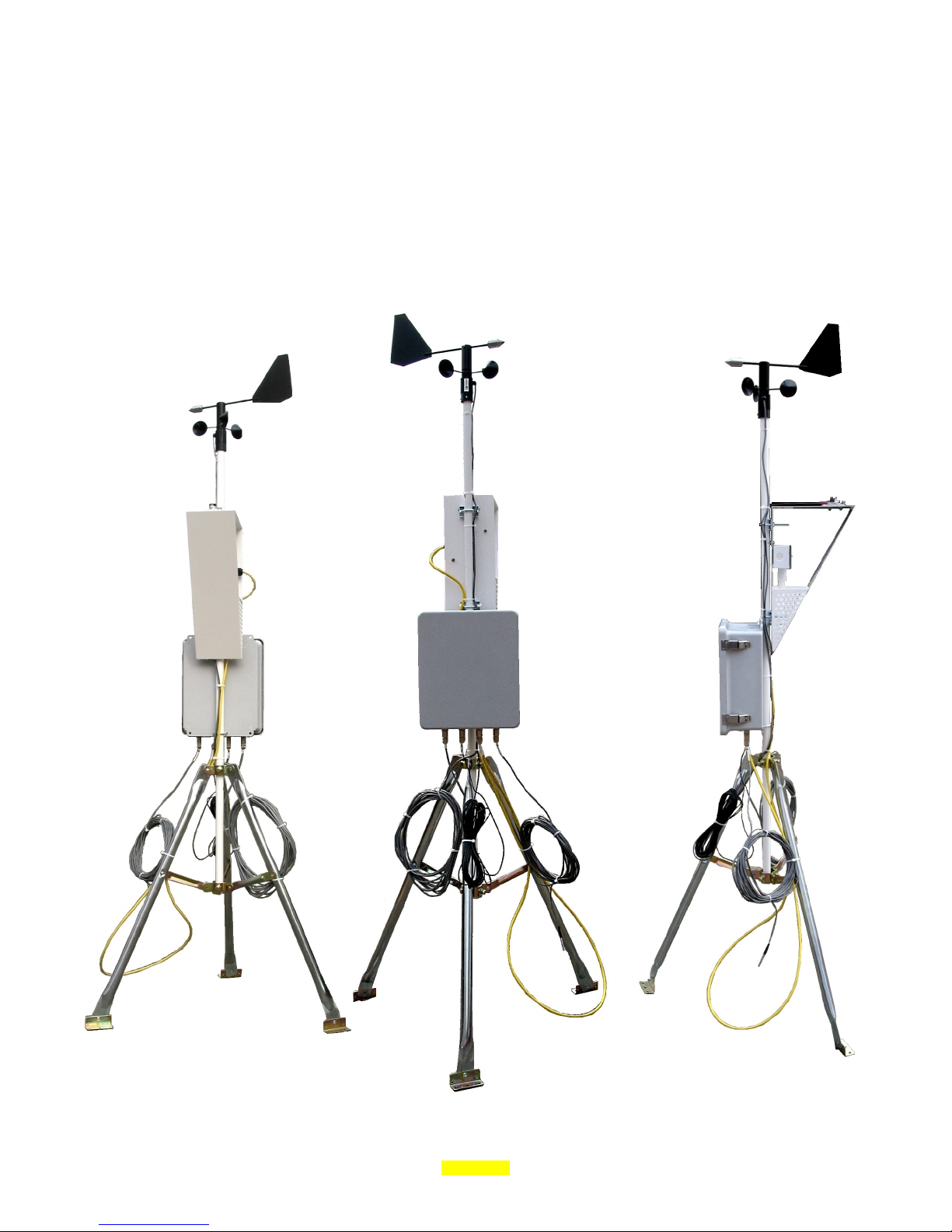
The Obvius weather station is designed to provide measurement options for environmental data points related to Solar/PV
generation sites. The weather station can provide readings for wind speed, direction, solar radiation, air temperature,
humidity, and solar panel temperature.
Installation Checklist
The installation of the Obvius weather station requires a number of tools and supplies to complete the installation. The
following list provides a representative sample of what may be required for installation, however site specific issues may
require additional tools or supplies.
The weather station power and communications connections require a licensed electrician or similarly qualified installer.
Required:
• Adjustable Crescent wrench
• Screw Drivers: Philips and flat-head, small and medium sizes.
• Weatherproof conduit for power and communications to the weather station control box.
• Drill and bit to install conduit connectors into the control box.
• Power: 120 ~ 240VAC, and appropriate wire.
• Communications RS485 wiring: twisted pair with shield.
• Compass or GPS to align wind sensor true North.
• Mounting screws or bolts to attach the tripod to the mounting location, such as nine 2”X1/4” bolts.
Markings and Symbols
WARNING: A potential risk exists if the operating instructions are not followed
General Warning Symbol: This symbol indicates the need to consult the operating instructions provided with the
product.
This symbol indicates the presence of electric shock hazards.
This symbol indicates: Do not apply to or remove from hazardous live conductors.
Direct Current symbol.
Page 4 Draft Copy A89WS Weather Station (gen 3)
Page 5

Hardware Overview
weather station Package Kits
The Weather station may be ordered using the following kit part numbers. These kits include a number of components that
are listed below, to build a complete weather station.
A89WS-1
A89WS-2
A89WS-3
A89WS-4
weather station with Pyranometer, Temperature, Humidity, and Cell Temperature.
Includes:
A89WS-PY1 Pyranometer kit (Li-cor)
A89WS-TH1 Temperature Humidity kit (Veris)
A89WS-TC1 Cell Temperature kit (Veris)
YWX0482 NEMA 4x control box with 120v power supply, UCLC amplifier, Flex IO, and sensor
connectors.
Does not include mounting kit.
weather station with Pyranometer, Temperature Only, and Cell Temperature.
Includes:
A89WS-PY1 Pyranometer kit (Li-cor)
A89WS-TO1 Temperature only kit (Veris)
A89WS-TC1 Cell Temperature kit (Veris)
YWX0482 NEMA 4x control box with 120v power supply, UCLC amplifier, Flex IO, and sensor
connectors.
Does not include mounting kit.
weather station with Pyranometer, Temperature, Humidity, Cell Temperature and Anemometer.
Includes:
A89WS-PY1 Pyranometer kit (Li-cor)
A89WS-AN1 Anemometer kit (NovaLynx)
A89WS-TH1 Temperature Humidity kit (Veris)
A89WS-TC1 Cell Temperature kit (Veris)
YWX0483 NEMA 4x control box with 120v power supply, UCLC amplifier, Anemometer Amplifier,
Flex IO, and sensor connectors.
Does not include mounting kit.
weather station with Pyranometer, Temperature, Cell Temperature and Anemometer.
Includes:
A89WS-PY1 Pyranometer kit (Li-cor)
A89WS-AN1 Anemometer kit (NovaLynx)
A89WS-TO1 Temperature Only kit (Veris)
A89WS-TC1 Cell Temperature kit (Veris)
YWX0483 NEMA 4x control box with 120v power supply, UCLC amplifier, Anemometer Amplifier,
Flex IO, and sensor connectors.
Does not include mounting kit.
Note: Weather station kits do not include a mounting kit (mast, tripod, etc). If a mounting kit is required, be sure to order
the weather station mounting kit package A89WS-MK1.
Note: The pyranometer kit is intended to be mounted vertically on the weather station. The optional kit A89WS-MP1
should be ordered separately for sites that require the pyranometer to be mounted on the solar panel to match the panel's
angle.
Page 5 Draft Copy A89WS Weather Station (gen 3)
Page 6

List of sub-assemblies
Weather station sub-assemblies may be ordered from the following list of components. Each section of this manual will deal
with these sub-assemblies separately as well.
A89WS-AN1
A89WS-AN2
A89WS-MK1
A89WS-MP1
A89WS-PY1
A89WS-TC1
A89WS-TC2
A89WS-TH1
A89WS-TO1
YWX0482
YWX0483
Anemometer kit.
Includes: wind speed and direction, 40' cable, and plug. (NovaLynx 200-WS-02)
Anemometer kit.
Includes: wind speed and direction, custom length 105' cable, and plug. (NovaLynx 200-WS-02)
weather station Mounting kit.
Includes: Tripod, Mast and Arm
PV Mounting Bracket - Pyranometer
Pyranometer kit.
Li-Cor LI-200SZ sensor with leveling mounting plate, screws, calibration certificate, 50' cable and
plug adapter.
Cell Temperature kit
Includes: 10k type 2 thermistor with 50' cable and plug adapter (Veris TRASPC01331)
Cell Temperature kit
Includes: 10k type 2 thermistor with 150' cable and plug adapter (Veris TRASPC01331)
Temperature/Humidity Probe kit.
4-20mA output, -40F to 122F range, 0-100% RH range, with 9ft cable, plug, and mounting screws.
(Veris HO2XMSTA1-02)
Temperature only probe kit.
4-20mA output, -40F to 122F range, with 9ft cable, plug, and mounting screws. (Veris TOAM10-02)
Weather station control box- NEMA 4x, 24VDC power supply, UCLC amplifier, 2 plug receptaclesPyranometer control box, Cell temperature, water tight gasket.
Weather station- NEMA 4x, 24VDC power supply, UCLC amplifier, 3 plug receptacles- Pyranometer,
Anemometer, water tight gasket.
Page 6 Draft Copy A89WS Weather Station (gen 3)
Page 7

Features and Specifications
List of sub-assemblies
A89WS-AN1, AN2 Anemometer kit
Direction Sensor range: 0 – 360 degrees. Azimuth: 360
Direction Accuracy: +/- 3º
Speed Sensor range: 0 – 100 MPH. Gusts up to 220 MPH
Speed Accuracy: 1 mph or +/- 3%
Operating temperature: -50C ~ +50C
A89WS-PY1 Pyranometer kit
Sensor range: 0 ~ 1400W/m
Accuracy: +/- 5%
Operating temperature: -40 ~ +65C
2
o
mechanical, 355o electrical (5o open) 360o/0o=North 90o=East 180o=South 270o=West
A89WS-TC1, TC2 Cell Temperature Kit
Sensor range: -13 ~ +221F. 10K Type 2 resistive sensor.
Accuracy: +/- 1.8°C typical; +/- 3.0°C max. over 0° to 70°C
Operating temperature: -25 ~ +125C
A89WS-TH1 Air Temperature and Humidity Probe.
Temp Sensor range: -40 ~ +122 degrees Fahrenheit
Temp Accuracy: +/-1 degree F
Humidity Sensor range: 0 ~ 100 % Relative Humidity
Humidity Accuracy: +/- 2% (replaceable sensor)
Operating temperature: -40 ~ +122
A89WS-TO1 Air Temperature Probe.
Sensor range: -40 ~ +122 degrees Fahrenheit
Accuracy: +/-1 degree F
Operating temperature: -40 ~ +122
YWX0431, YWX0432 weather station Control Box
Control Box
Operating Temperature: -30 ~ +50c, 0-95% RH, non-condensing.
Power Supply: Weidmuller 8739140000
Power input: 120-240VAC, 24W, 50-60Hz
Operating temperature: -10 ~ +70c
IO module: A8332-8F2D
Accuracy: +/- 0.25% (4-20mA mode inputs) +/- 1% for cell temperature sensor (resistive mode inputs)
Operating temperature: -30 ~ +70c
Protocol: Modbus/RTU, RS-485, 9600, N81
Page 7 Draft Copy A89WS Weather Station (gen 3)
Page 8
Hardware Installation
Overview
The weather station assembly takes several steps, and should be performed in the following order.
1) Assemble the mounting kit. Tripod, mast, and arm.
2) Attach the weather station control box. Run appropriate conduit for power and communications to the control box.
3) Attach individual sensors to the weather station.
4) Using a computer or laptop, configure the weather station and the AcquiSuite (or other Modbus data acquisition
server).
The following sections of the manual cover hardware installation and component details for each of the steps listed above.
Page 8 Draft Copy A89WS Weather Station (gen 3)
Page 9
A89WS-MK1: weather station Mounting kit
Kit contains: Tripod, Mast, and Arm.
Location: Before installing the weather station, a suitable location for the sensors must be selected. Ensure that the
weather station is located in as open and unobstructed area as possible such as a rooftop location or a parking lot shade
structure. Use extreme care to prevent contact with electrical power lines while installing the weather station.
• The pyranometer measures solar radiation. The main concern during installation is an unobstructed view of the sky,
clear of all walls, trees, or other objects which might cast a shadow over the sensor.
• The wind speed and direction sensor must be installed in a location away from walls or other objects that can
obstruct the flow of the wind. Vertically position the sensor twice the height above adjacent obstructions, and
horizontally position the sensor away from adjacent obstructions six times times the height of the obstruction. For
best performance, position the wind sensor approximately 33 feet (10 meters) above the highest obstacle within a
990 foot (300 meter) radius of the mounting location.
• It is critical to avoid placing the weather station near HVAC units, or exhaust systems from other mechanical
equipment to avoid interference with the sensors.
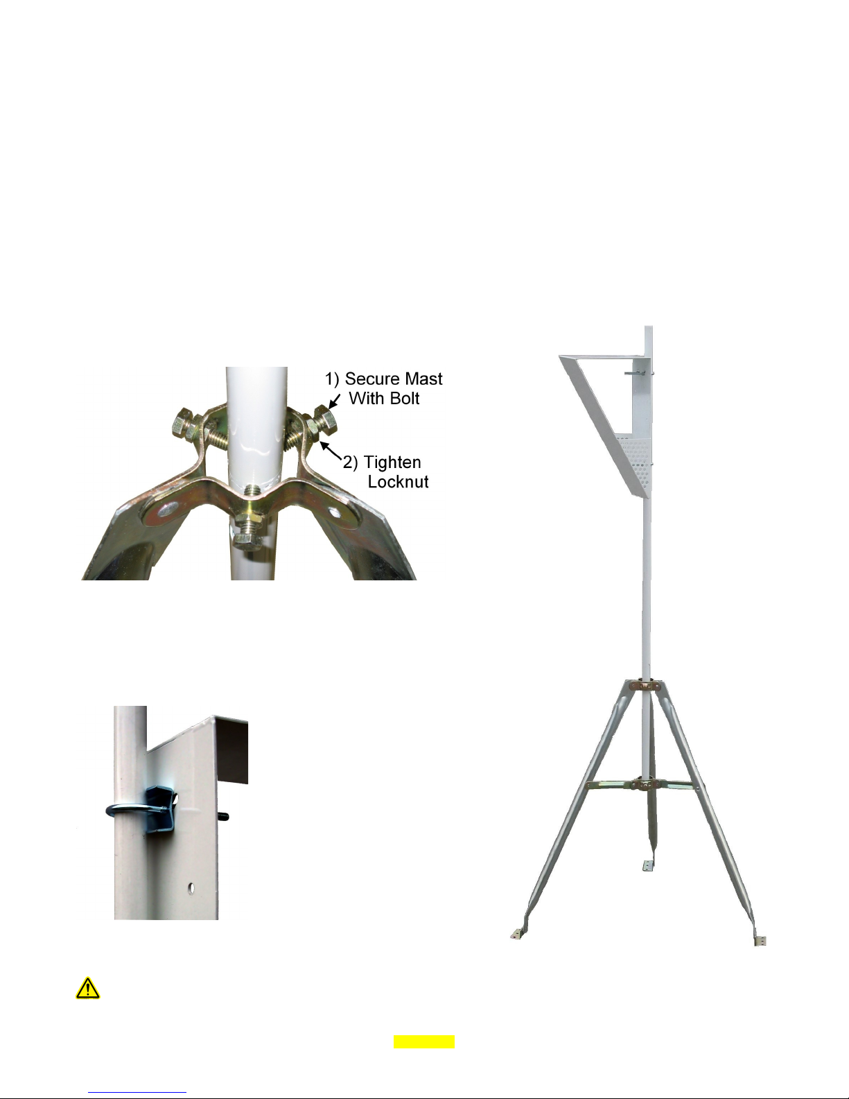
Tripod: Remove the tripod from the packaging. Expand the tripod legs until
the legs are fully extended.
Mast: Install the mast in the hole in the center of the tripod, and secure using
the bolts in the tripod collars. Tighten the bolt into the mast, and the secure
the bolt by tightening the lock nut against the collar. The nut and bolt require
a ½” wrench.
Arm: The arm of the weather station
should be positioned on the mast about 8”
from the top, and pointing towards the
equator to prevent the mast from casting a
shadow on the pyranometer.
Use the two u-bolts provided to attach the
arm to the mast. Place the u-bolt around
the back of the mast, then add the metal
adapter bracket. Next, pass the bolts
through the back of the arm. Add the lock
washer and nut on the inside of the arm.
The mast and tripod should be electrically grounded to minimize the probability of any lightning damage.
Page 9 Draft Copy A89WS Weather Station (gen 3)
Page 10

YWX0482: weather station Control Box
Kit includes: control box, 2 u-bolts.
The weather station control box mounts on the back of the mast using the two u-bolts provided in the kit. The box should be
mounted with the connectors on the bottom.
Separate holes will need to be drilled into the side or bottom of the box by the installer, to provide an attachment point for a
weatherproof conduit or cable for power and communications. (power and communications wire and conduit are not
included with the weather station.)
With the mains off, connect the Line, Neutral and Ground wires to the screw terminals provided. Proper grounding is
required.
It is important to observe all electrical codes and safety practices when wiring the weather station.
WARNING: After wiring the system, remove all scraps of wire or foil shield from the electrical panel. This
could be dangerous if wire scraps come into contact with high voltage wires.
Page 10 Draft Copy A89WS Weather Station (gen 3)
Page 11

The weather station uses RS-485 Modbus RTU to communicate with a Master device such as an AcquiSuite. Attach a
suitable twisted pair cable to the RS-485 connector provided. Observe polarity markings +, - and Shield.
Page 11 Draft Copy A89WS Weather Station (gen 3)
Page 12

Page 12 Draft Copy A89WS Weather Station (gen 3)
Page 13

YWX0483: weather station Control Box
Kit includes: control box, 2 u-bolts.
The weather station control box mounts on the back of the mast using the two u-bolts provided in the kit. The box should be
mounted with the connectors on the bottom.
Separate holes will need to be drilled into the side or bottom of the box by the installer, to provide an attachment point for a
weatherproof conduit or cable for power and communications (power and communications wire and conduit are not included
with the weather station).
With the mains off, connect the Line, Neutral and Ground wires to the screw terminals provided. Proper grounding is
required.
It is important to observe all electrical codes and safety practices when wiring the weather station.
WARNING: After wiring the system, remove all scraps of wire or foil shield from the electrical panel. This
could be dangerous if wire scraps come into contact with high voltage wires.
Page 13 Draft Copy A89WS Weather Station (gen 3)
Page 14

The weather station uses RS-485 Modbus RTU to communicate with a Master device such as an AcquiSuite. Attach a
suitable twisted pair cable to the RS-485 connector provided. Observe polarity markings +, - and Shield.
Page 14 Draft Copy A89WS Weather Station (gen 3)
Page 15

Page 15 Draft Copy A89WS Weather Station (gen 3)
Page 16

A89WS-AN1, A89WS-AN2: Anemometer kit
Kit contains: Anemometer sensor
The A89WS-AN1 and A89WS-AN2 sensor kits are identical except for the cable length. The A89WS-AN1 has a 40' cable.
The A89WS-AN2 has a 105' cable. The installation procedure for both kits is the same.
Locate the tail fin for the wind direction sensor. The tail fin must be attached to the sensor using two screws provided.
Place the tail fin with the large part of the fin on the top as shown in the following picture.
Install the anemometer by placing the sensor on the top of the mast. Locate the label on the side of the sensor labeled
“north”. Rotate the anemometer on the pole so that label on the anemometer base is facing North. Magnetic North is
adequate for most installations. Should a True North alignment be required, the magnetic declination at the sensor location
must known and applied to the compass reading.
Tighten the two screws on the bottom of the sensor to secure it to the mast.
Note: do not adjust the screw in the middle of the label. This is for calibration.
Run the wire from the sensor back to the control box, and attach the wire to the connector labeled “Anemometer.”
Page 16 Draft Copy A89WS Weather Station (gen 3)
Page 17

A89WS-PY1: Pyranometer kit
Kit contains: Pyranometer, Leveling base, 3 screws, nuts, calibration certificate.
Attach the pyranometer to the mounting base. Align the wire on
the pyranometer to the slot on the mounting base before inserting
it in the base. A small hex set-screw is located on the side on the
mounting base to secure the pyranometer. Use the Allen wrench
provided to tighten the set screw until the pyranometer is secure.
Do not over-tighten the set screw or it will crack the pyranometer.
Attach the pyranometer base plate to the top of the weather station
arm as shown to the left. Place the three mounting bolts in the
holes, and start the bolts, but do not tighten the nuts yet.
Using the leveling screws, adjust the angle of the base plate until
the bubble level shows the pyranometer to be level. Once this
adjustment has been made, tighten the attachment bolts and nuts to
secure the pyranometer in place. Do not over-tighten the leveling
screws more than finger tight.
Bring the black cable down the mast and around to the control box. Plug the cable into the connector labeled
“pyranometer”
Important: Locate the serial number on the pyranometer. Write this number down ----> ______________________
The serial number will be required later for calibration purposes.
The pyranometer kit includes a calibration certificate. Do NOT DISCARD THE CALIBRATION CERTIFICATE. Take
time to verify the serial number printed on the calibration certificate matches the one on the pyranometer sensor.
Page 17 Draft Copy A89WS Weather Station (gen 3)
Page 18

A89WS-MP1: PV Mounting Bracket – Pyranometer (Optional)
Kit contains: bracket with thumbscrews.
The A89WS-MP1 mounting bracket allows the pyranometer to be mounted on the side
of a solar panel or other flat object. This provides the pyranometer the same angle to
the sun as the panel for measuring performance of a system.
Note: the pyranometer is not included with this bracket. The A89WS-PY1 kit is
required to use this bracket.
Attach the pyranometer to the mounting base. Align the wire on the pyranometer to
the slot on the mounting base before inserting it in the base. A small hex set-screw is
located on the side on the mounting base to secure the pyranometer. Use the Allen
wrench provided to tighten the set screw until the pyranometer is secure. Do not overtighten the set screw or it will crack the pyranometer.
Attach the pyranometer base plate to the top of the A89WS-MP1 mounting bracket as
shown to the left. Place the three mounting bolts in the holes, and tighten the
attachment bolts and nuts to secure the pyranometer in place flush against the bracket.
The leveling screws and bubble level are not used with this mounting bracket.
Bring the black cable around to the control box. Plug the cable into the connector
labeled “pyranometer”
Important: Locate the serial number on the pyranometer.
Write this number down ----> ______________________
The serial number will be required later for calibration purposes.
The pyranometer kit includes a calibration certificate. Do NOT DISCARD THE
CALIBRATION CERTIFICATE. Take time to verify the serial number printed on
the calibration certificate matches the one on the pyranometer sensor.
Page 18 Draft Copy A89WS Weather Station (gen 3)
Page 19

A89WS-TC1, A89WS-TC2: Cell Temperature Kit
Kit contains: Cell temperature probe with cable and plug.
The cell temperature probe is a 10k ohm type 2 thermistor sensor
in a bullet probe configuration. The kit comes in two versions:
• TC1 has a 50' cable.
• TC2 has a 150' cable.
The cell temperature probe should be mounted to the back of a
solar panel to measure the panel temperature. Care should be
taken to not damage the solar panel when installing the sensor.
The bullet probe can be glued to the panel, or attached by securing
the probe with a hardware attachment on the panel or panel
holding system.
The probe may also be secured using durable foil tape typically used to seal HVAC systems in outdoor applications. Foil
tape can also be used to secure a probe while glue such as epoxy is curing.
Page 19 Draft Copy A89WS Weather Station (gen 3)
Page 20

A89WS-TH1: Air Temperature and Humidity Probe
A89WS-TO1: Air Temperature Probe
Note: The A89WS-TH1 and TO1 kits have a similar appearance and the hardware mounting is the same. The only
difference is that the A89WS-TH1 kit includes a humidity sensor in the air probe, and the A89WS-TO1 air probe does not.
For purposes of installation, the hardware assembly is the same.
Kit contains: Air sensor with cable, 2 screws, nuts.
Install the air sensor on the inside of the weather station mounting
arm with the probe facing down. The probe should be oriented
so that the sensor is in the vented sun shade area of the arm.
Use the two screws provided to attach the sensor to the arm.
Secure the screws using the nut on the
back of the arm. Tighten the screws
until the air sensor box is flush against
the back of the mounting arm.
Bring the yellow cable down the mast
and around to the control box. Plug
the cable into the connector labeled
“temp/humidity”
Page 20 Draft Copy A89WS Weather Station (gen 3)
Page 21

Software setup and configuration
The Obvius A89WS weather station uses an A8332-8F2D I/O Module to convert the sensor data to a Modbus output. The
A8332-8F2D must be configured to read each of the sensors. Each input on the A8332-8F2D represents a specific sensor
input, and two inputs remain unused.
Note: the default configuration of the weather station I/O Module is Modbus address 51, 9600, N81
Modbus Configuration
Default Input mode configuration:
Input channel 1: Air Temperature (4-20mA)
Input channel 2: Air Humidity (4-20mA)
Input channel 3: Pyranometer (4-20mA)
Input channel 4: Cell Temperature (resistance)
Input channel 5: Wind Speed (4-20mA)
Input channel 6: Wind Direction (4-20mA)
Input channel 7: (not used)
Input channel 8: (not used)
Note: Some weather station configurations may not use all the sensors listed above. The input channels associated with these
sensors should be disabled if the sensor is not present. Use the OCC software or the AcquiSuite configuration menu to
disable channels with no sensor attached.
Note: The YWX0483 (rev A) control box shipped between Aug and Sep 2010 have a different wiring connection list. The inputs are
configured as 1= wind speed, 2=direction, 3=temp, 4=humidity, 5=pyranometer, 6=cell temp. For more information on the rev-a model
of this control box, please contact technical support at Obvius.
Modbus Address and Dipswitch Configuration
Modbus Address: The default Modbus address of the weather station A8332-8F2D I/O
Module is set to 051. The address may be modified by changing the Modbus address
dipswitches on the A8332-8F2D I/O Module. This address must be unique among all
Modbus devices in the system. The A8332-8F2D supports address 001 through 127.
Select an address, and set the dipswitches to match.
The sum of the value of the switches is the address. In the example to the right, address
51 is set by placing switch 1, 2, 16 and 32 to the on position.
Note: 1 + 2 + 16 + 32 = 51
Baud Rate: This option sets the serial port speed for the RS-485 port. Set this option to
“off” for 19200. Set the switch to “on” for 9600 baud. The default is 9600 (on)
Page 21 Draft Copy A89WS Weather Station (gen 3)
Page 22

Setup and testing with Obvius Config Console (OCC) (optional)
After the weather station has been installed and powered, the installer should take the time to verify that all the sensors are
working properly. One way to do this is to use an AcquiSuite data acquisition server to configure and display the data points
from the weather station. If an AcquiSuite is not available, a free software tool can be downloaded from obvius.com that can
help with both configuration and confirm the operation of the device.
Using a USB to Serial adapter, connect a laptop computer to the Flex IO module inside the control box. Either an RS-485 or
RS232 adapter may be used. Obvius sells two adapters (A89-USB485 or A89-USB232) that may be used. Verify that the
I/O Module inside the weather station control box is powered and has a blinking green LED.
Next, run the OCC software. On the connection screen, select your serial port, and specify 9600, N,8,1 serial options, and
click Connect. Click the Scan button on the top of the page to scan the serial port for devices. Device #051 (A8332-8F2D)
should appear in the list. Double click on the line item for this Flex I/O Module. You should see something like this screen:
Verify the following options and readings:
Input channel 1 Current 4-20mA
Input channel 2 Current 4-20mA
Input channel 3 Current 4-20mA
Input channel 4 Resistance
Input channel 5 Current 4-20mA
Input channel 6 Current 4-20mA
Input channel 7 Unconfigured
Input channel 8 Unconfigured
Page 22 Draft Copy A89WS Weather Station (gen 3)
Page 23

Setup with Obvius AcquiSuite
Configure the AcquiSuite Modbus options to allow 9600 baud communications. The default settings in the AcquiSuite
should allow the weather station io to communicate directly. Select the Modbus Device List option from the AcquiSuite
configuration menu. The following screen should be displayed. Notice the weather station shows up in the list at address
51. The actual device type is that of the io module, an Obvius A8332-8F2D.
Select the weather station device 51 from the device list. Next, click the configure button at the bottom of the page. Each
data point will now have a “Configure Point” button open to the right of each data point. To configure each input sensor,
click each configure point button, and set the options as described in the following sections.
Channel 1: A89WS-TH1, TO1: Air Temperature Probe
Configure the following options
• Sensor Name: “Air Temperature”
• Input Mode: “Current 4-20mA”
• Sensor Make and Model:
“A89WS-TH1 (Veris HO2XMSTA1-02)”
• Sensor Minimum Range: “-40”
• Sensor Maximum Range: “122”
• Engineering Units: “Degrees F”
Note: the option for “Sensor make and model” is for reference
information only. This field is intended to store information
about the physical sensor to assist in record-keeping for
identification of the attached sensor.
Page 23 Draft Copy A89WS Weather Station (gen 3)
Page 24

Channel 2: A89WS-TH1: Air Humidity Probe
Configure the following options
• Sensor Name: “Air Humidity”
• Input Mode: “Current 4-20mA”
• Sensor Make and Model:
“A89WS-TH1 Veris HO2XMSTA1-02”
• Sensor Minimum Range: “0”
• Sensor Maximum Range: “100”
• Engineering Units: “%RH”
Note: the option for “Sensor make and model” is for reference
information only. This field is intended to store information
about the physical sensor to assist in record keeping for
identification of the attached sensor.
Channel 3: A89WS-PY1: Pyranometer
Configure the following options
• Sensor Name: “Solar Radiation”
• Input Mode: “Current 4-20mA”
• Sensor Make and Model:
“A89WS-PY1 (Li-Cor LI-200SZ)”
• Sensor Minimum Range: “0”
• Sensor Maximum Range: “xxxx” *
• Engineering Units: “W/m^2”
Note: the option for “Sensor make and model” is for reference
information only. This field is intended to store information
about the physical sensor to assist in record keeping for
identification of the attached sensor.
* Pyranometer max range calculation:
The Sensor Maximum Range setting for the pyranometer is based on the multiplier supplied on the calibration certificate for
the sensor. Locate the multiplier on the calibration certificate. If the calibration certificate is not available, use a web
browser to access the LI-COR website at http://envsupport.licor.com Choose the Calibration Data option at the bottom of
the page and enter the serial number on the Pyranometer. The multiplier is different for each pyranometer.
Using the multiplier from the calibration certificate, multiply the absolute (positive) value by 125. The result is the Sensor
Maximum Range. e.g. Maximum Range = 125 * LicorMultiplier.
Example: LI-COR multiplier of -11.33
Maximum Range = 125 * 11.33
Maximum Range = 1416.25 w/m^2
Page 24 Draft Copy A89WS Weather Station (gen 3)
Page 25

Channel 4: A89WS-TC1,TC2: Cell Temperature
Configure the following options
• Sensor Name: “Cell Temperature”
• Input Mode: “Resistance”
• Sensor Make and Model:
“A89WS-TC1 (Veris TRASPC01331)”
• Curve Scale: “Veris 10K Type 2”
• Engineering Units: “Degrees F”
Note: the option for “Sensor make and model” is for reference
information only. This field is intended to store information
about the physical sensor to assist in record keeping for
identification of the attached sensor.
The Curve Scale option has a provision for converting 10K Type 2 to either Degreees F or C. You may select either
conversion depending on your project needs. Be sure to set the Engineering Units field to match the unit of measure for
your conversion.
Channel 5: A89WS-AN1,AN2: Anemometer / wind speed
Configure the following options
• Sensor Name: “Wind Speed”
• Input Mode: “Current 4-20mA”
• Sensor Make and Model:
“A89WS-AN1 (NovaLynx 200-WS-02)”
• Sensor Minimum Range: “0”
• Sensor Maximum Range: “100”
• Engineering Units: “MPH”
Note: the option for “Sensor make and model” is for reference
information only. This field is intended to store information
about the physical sensor to assist in record keeping for
identification of the attached sensor.
Page 25 Draft Copy A89WS Weather Station (gen 3)
Page 26

Channel 6: A89WS-AN1,AN2: Anemometer / wind direction
Configure the following options
• Sensor Name: “Wind Direction”
• Input Mode: “Current 4-20mA”
• Sensor Make and Model:
“A89WS-AN1 (NovaLynx 200-WS-02)”
• Sensor Minimum Range: “0”
• Sensor Maximum Range: “360”
• Engineering Units: “Degrees”
Note: the option for “Sensor make and model” is for reference
information only. This field is intended to store information
about the physical sensor to assist in record keeping for
identification of the attached sensor.
Channel 7, Channel 8
Channels 7 and 8 are not used in the weather station. Set these channels to be unconfigured:
• Input Mode: “Unconfigured”
Page 26 Draft Copy A89WS Weather Station (gen 3)
Page 27

Setup with 3rd party Modbus master
Flex I/O Module Modbus information, specific to the Weather Station
(For complete details such as reserved or pulse input registers or values not listed here, refer to the latest Obvius
documentation regarding the A8332-8F2D Modbus Flex IO Module Installation and Operation Manual).
Weather Station Modbus Register Listing
Data points
offset point type description and modes
Values (instantaneous Ohms or mA)
0 40001 UINT32 input 1 value MSW
1 40002 UINT32 input 1 value LSW
2 40003 UINT32 input 2 value MSW
3 40004 UINT32 input 2 value LSW
4 40005 UINT32 input 3 value MSW
5 40006 UINT32 input 3 value LSW
6 40007 UINT32 input 4 value MSW
7 40008 UINT32 input 4 value LSW
8 40009 UINT32 input 5 value MSW
9 40010 UINT32 input 5 value LSW
10 40011 UINT32 input 6 value MSW
11 40012 UINT32 input 6 value LSW
12 40013 UINT32 input 7 value MSW
13 40014 UINT32 input 7 value LSW
14 40015 UINT32 input 8 value MSW
15 40016 UINT32 input 8 value LSW
Average (Ohms or mA)
16 40017 UINT32 input 1 ave MSW
17 40018 UINT32 input 1 ave LSW
18 40019 UINT32 input 2 ave MSW
19 40020 UINT32 input 2 ave LSW
20 40021 UINT32 input 3 ave MSW
21 40022 UINT32 input 3 ave LSW
22 40023 UINT32 input 4 ave MSW
23 40024 UINT32 input 4 ave LSW
24 40025 UINT32 input 5 ave MSW
25 40026 UINT32 input 5 ave LSW
26 40027 UINT32 input 6 ave MSW
27 40028 UINT32 input 6 ave LSW
Page 27 Draft Copy A89WS Weather Station (gen 3)
Page 28

28 40029 UINT32 input 7 ave MSW
29 40030 UINT32 input 7 ave LSW
30 40031 UINT32 input 8 ave MSW
31 40032 UINT32 input 8 ave LSW
Minimum (Ohms or mA)
32 40033 UINT32 input 1 min MSW
33 40034 UINT32 input 1 min LSW
34 40035 UINT32 input 2 min MSW
35 40036 UINT32 input 2 min LSW
36 40037 UINT32 input 3 min MSW
37 40038 UINT32 input 3 min LSW
38 40039 UINT32 input 4 min MSW
39 40040 UINT32 input 4 min LSW
40 40041 UINT32 input 5 min MSW
41 40042 UINT32 input 5 min LSW
42 40043 UINT32 input 6 min MSW
43 40044 UINT32 input 6 min LSW
44 40045 UINT32 input 7 min MSW
45 40046 UINT32 input 7 min LSW
46 40047 UINT32 input 8 min MSW
47 40048 UINT32 input 8 min LSW
Maximum (Ohms or mA)
48 40049 UINT32 input 1 max MSW
49 40050 UINT32 input 1 max LSW
50 40051 UINT32 input 2 max MSW
51 40052 UINT32 input 2 max LSW
52 40053 UINT32 input 3 max MSW
53 40054 UINT32 input 3 max LSW
54 40055 UINT32 input 4 max MSW
55 40056 UINT32 input 4 max LSW
56 40057 UINT32 input 5 max MSW
57 40058 UINT32 input 5 max LSW
58 40059 UINT32 input 6 max MSW
59 40060 UINT32 input 6 max LSW
60 40061 UINT32 input 7 max MSW
61 40062 UINT32 input 7 max LSW
62 40063 UINT32 input 8 max MSW
63 40064 UINT32 input 8 max LSW
Page 28 Draft Copy A89WS Weather Station (gen 3)
Page 29

Mode setting options (see above for value details)
64 40065 UINT16 input 1 mode (NV/r/w)
65 40066 UINT16 input 2 mode (NV/r/w)
66 40067 UINT16 input 3 mode (NV/r/w)
67 40068 UINT16 input 4 mode (NV/r/w)
68 40069 UINT16 input 5 mode (NV/r/w)
69 40070 UINT16 input 6 mode (NV/r/w)
70 40071 UINT16 input 7 mode (NV/r/w)
71 40072 UINT16 input 8 mode (NV/r/w)
73 40074 UINT16 input broken wire alarm bitmap. (resistance, current modes only) Resistive mode: bit
set when resistance is off-scale-high. 4-20mA mode: bit is set when current is below
4mA.
74 40075 UINT16 relay output 1 (r/w) 0=open, 1=closed, defaults to open on power-up. r/w allowed when
register 41030 = 0.
75 40076 UINT16 relay output 2 (r/w) 0=open, 1=closed
System settings and information
1002 41003 UINT16 serial number bytes 1,2
1003 41004 UINT16 serial number bytes 3,4
1004 41005 UINT16 serial number bytes 5,6
1005 41006 UINT16 firmware version (major)
1006 41007 UINT16 firmware version (minor)
1011 41012 UINT32 uptime MSW number of seconds since IO module booted.
1012 41013 UINT32 uptime LSW
1013 41014 UINT16 hardware version (major) for example: 8332
1014 41015 UINT16 hardware version (minor) MSB = pcb rev, LSB = part rev. value 1=Rev_A, 2=Rev_B,
etc.
1015 41016 UINT32 hardware Date of Manufacture (MSW)
1016 41017 UINT32 hardware Date of Manufacture (LSW) time, UTC, unix epoch, seconds past 1970.
1017 41018 UINT16 RS485 Stats: Good RX (all packets received)
1018 41019 UINT16 RS485 Stats: Total TX
1019 41020 UINT16 RS485 Stats: TX failed
1020 41021 UINT16 clear min/max/ave (r/w) read returns 0, write any value to clear min/max/ave for all
channels.
1024 41025 UINT8 reason for reboot. 0x01=POR, 0x02=EXTR 0x04=WDTR
0x08=BODR,0x8000=WDTOF
1025 41026 UINT16 power supply voltage monitor. scale: x100, volts
1026 41027 INT16 pcb temperature monitor. scale: x100, degrees F.
1027 41028 UINT16 5V internal power supply voltage monitor. scale: x100, volts
1028 41029 UINT16 RS485 baud rate. 2=9600, 3=19200.
Modbus function 0x11 Slave ID response will report the following:
"Obvius, A8332-8F2D, IO Module, 8-Flex, 2-DO", id=48
Page 29 Draft Copy A89WS Weather Station (gen 3)
Page 30

Register Functions
All 32 bit data point values are encoded in 2 Modbus registers (16bits each). Modbus master systems should always query
the A8332-8F2D using a single query to read an entire block of registers. Never use two queries to read one register and
then combine the two results into a single 32 bit value. Doing so will allow the input value to increment in the middle of the
two Modbus queries, and will cause intermittent data readings that are incorrect.
For example, an input has a decimal value of 65534. This is represented as a 32 bit hex number 0x0000FFFE. The first 4
digits are the MSW register, the second 4 digits are the LSW register. The Modbus Master reads the first (MSW) register
and gets 0x0000. In the moment between the two readings, the input raises 2 more digits (in decimal), making the total
65536 or 0x00010000 in hex. Next the Master reads the second (LSW) register and gets 0x0000. When the two registers
are combined, the result is 0x00000000. The proper way to handle this situation is to simply read both registers in a single
Modbus query.
Data Conversion
Knowing the register values and types, and expected ranges of resultant values, calculate to derive the sensor readings from
the Modbus register values listed above.
Example
Registers 40001 and 40002 typically describe an Air Temperature reading from a 4-20mA sensor on Input 1. The expected
minimum sensor value (in degrees F) is -40º F and the maximum is 122º F.
The minimum value is two unsigned 32-bit integers, MSW=0, LSW=0, and the maximum is MSW=65535, LSW=65535.
To calculate a single value x from those by combining each register R
add it the lower register value, as follows.
, shift the higher word register value in order to
[
]
address
x = ( R
) * 10000 ) + ( R
40001
40002
)
Calculate the slope m for y as follows.
m = ( x2-x1 ) / ( y2-y1 ) = ( 6553565535-0 ) / ( 122--40 ) ≈ 39960765.457
So the approximate temperature T value is as follows.
T = ( ( ( ( register 40001 ) * 10000 ) + ( register 40002 ) ) / 39960765 ) - 40
If register 40001 was 32767, and register 40002 was 32767, then the resulting value would be interpreted as approximately
41.9º F, which is about half of the Air Temperature range listed above.
Use similar formulae to derive the values for the other sensors based on the register values for those types. Resistive
measurements may require curve scales.
Page 30 Draft Copy A89WS Weather Station (gen 3)
Page 31

Recommended Maintenance of third party devices
Some of the sensors included in the weather station require either replacement or re-calibration after
deployment.
A89WS-PY1: LI-COR recommends that the LI-200SZ Pyranometers be calibrated every two years to
maintain the sensor accuracy. This requires the device to be sent to LI-COR (402) 467-3576 for
recalibration.
A89WS-TH1: Veris recommends that the humidity element on the HO2XMSTA1-O2
Temperature/Humidity sensors be tested every year and replaced accordingly. This element is fieldreplaceable, and can be obtained by contacting Veris Industries (503) 598-4564 directly.
A89WS-AN1,AN2: NovaLynx recommends that you apply several drops of light weight (3-in-1)
machine oil or lightly spray WD40 onto the anemometer bearing located just below the cups. Always
look at the wind vane alignment to North. If the alignment is critical, do the check with a compass.
Make corrections to the alignment as needed. Always check the alignment after a severe storm with
high velocity winds.
Page 31 Draft Copy A89WS Weather Station (gen 3)
 Loading...