

Observint Technologies BLK-PTZJOY3 Instruction Manual

INSTRUCTION MANUAL
BLK-PTZJOY3 3-Axis Joystick Controller
BLK-PTZJOY3
TO REDUCE THE RISK OF FIRE OR ELECTRIC SHOCK, DO NOT EXPOSE THIS PRODUCT TO RAIN
OR MOISTURE. DO NOT INSERT ANY METALLIC OBJECTS THROUGH THE VENTILATION GRILLS OR
OTHER OPENINGS ON THE EQUIPMENT.
The lightning flash with arrowhead symbol, within
an equilateral triangle, is intended
To alert the user to the presence of un-insulated
"dangerous voltage" within the
product's enclosure that may be of sufficient
magnitude to constitute a risk of electric
shock to persons.
The exclamation point within an equilateral triangle
is intended to alert the user to
The presence of important operating and
maintenance (servicing) instruction in
the literature accompanying the product
WARNING
SYSTEM CONTROLLER
-2 -
FCC COMPLIANCE STATEMENT
FCC INFORMATION: THIS EQUIPMENT HAS BEEN TESTED AND FOUND TO COMPLY WITH THE LIMITS FOR A
CLASS A DIGITAL DEVICE, PURSUANT TO PART 15 OF THE FCC RULES. THESE LIMITS ARE DESIGNED TO
PROVIDE REASONABLE PROTECTION AGAINST HARMFUL INTERFERENCE WHEN THE EQUIPMENT IS
OPERATED IN A COMMERCIAL ENVIRONMENT. THIS EQUIPMENT GENERATES, USES, AND CAN RADIATE
RADIO FREQUENCY ENERGY AND IF NOT INSTALLED AND USED IN ACCORDANCE WITH THE INSTRUCTION
MANUAL, MAY CAUSE HARMFUL INTERFERENCE TO RADIO COMMUNICATIONS. OPERATION OF THIS
EQUIPMENT IN A RESIDENTIAL AREA IS LIKELY TO CAUSE HARMFUL INTERFERENCE IN WHICH CASE THE
USER WILL BE REQUIRED TO CORRECT THE INTERFERENCE AT HIS OWN EXPENSE.
CAUTION: CHANGES OR MODIFICATIONS NOT EXPRESSLY APPROVED BY THE PARTY RESPONSIBLE FOR
COMPLIANCE COULD VOID THE USER'S AUTHORITY TO OPERATE THE EQUIPMENT.
CE COMPLIANCE STATEMENT
WARNING
THIS IS A CLASS A PRODUCT. IN A DOMESTIC ENVIRONMENT THIS PRODUCT MAY CAUSE RADIO
INTERFERENCE IN WHICH CASE THE USER MAY BE REQUIRED TO TAKE ADEQUATE MEASURES.

CONTENTS
General Descriptions, Features ...……..………………………..…. 5
Installation ...................……………….....………………….…..……. 6
Part names & Functions …………………...………….…….……..…. 7
Display LCD window ……………………....………………….......….. 8
PTZ Control ....................…..….……………....…...……....….…… 9
PTZ Configuration ..........…..….……………....…...……....….…… 11
Hidden command …………………………………....………….…….. 12
Specifications & Dimensions ……...………....………………………. 13
SYSTEM CONTROLLER
-3 -

General Descriptions
The BLK-PTZJOY3 is a pan/tilt controller that allows operators
to perform the following functions :
• Controls camera functions such as pan, tilt, zoom, and focus.
• Sets and calls camera preset positions
• Activates pre-programmed group presets, tour and group sequences.
The LCD is used to display current status as well as to provide a menu system for setting
operational parameters.
Controller is designed for desktop operation; interface connectors are located in the Junctions box
outer of the unit.
Features
• Recalls up to 255 cameras from one keyboard.
• Multiple protocol supported in each channel (Pelco D, DRX-502)
• Preset position control.
• Variable manual control speed from 1°/sec to 90°/sec
• Maximum speeds are proportional to zoom ratio.
• Recalls programmed guard tours from each dome camera.
• Recalls Auto-Swing from selected dome camera.
• Built-in Graphic LCD monitor with blue screen.
• Programmable user preferences. (preset, tour, group, etc.).
• User password support.
• Supported DVR protocol (Need to be modified)
• Easy upload programmed data via serial communication port of computer.
• Slave Keyboard support.
SYSTEM CONTROLLER
-4 -
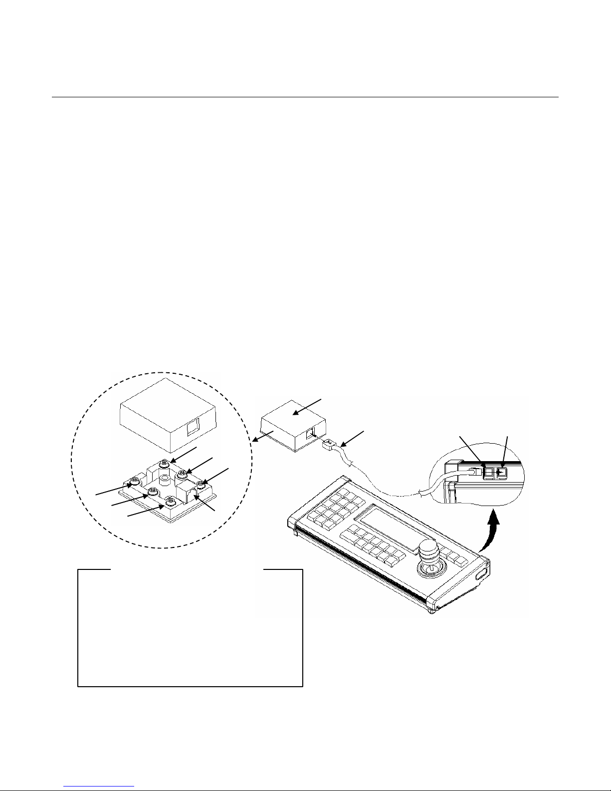
SYSTEM CONTROLLER
Junction Box
RJ-11 Cable
⑥
⑤
④
③
②
①
⑦
Slave Port Master Port
< Configuration of Junction Box >
① RS-485 (+) : Connect to PTZ (+)
② RS-485 (-) : Connect to PTZ(-)
③ Power input ((DC12V (-)) : Not used.
④Not used
⑤ Not used
⑥ Power input :DC12V (+)
⑦ RJ-11 Modular Jack : Connect to Controller
-5 -
UNPACKING
Unpack the equipment and make sure all listed items are included in the box.
Keyboard controller ………………………………………………….……… 1
Junction box ………………………………………………………….………. 2
3m 6p cable RJ-11………………………………………………….………… 2
Instruction manual ….………….…………………………………………….. 1
1. CONNECTIONS
There are two connectors on the controller. These connectors are RJ connector for Master and
Slave control.
1.1 Open the junction box cover and connect the 12VDC power to the junction box number 3 and 6.
(DC 12V, 500mA, Power adaptor is not included in the system box).
1.2 Connect 6-pin multi-wired cable between junction-box and keyboard.
1.3 Connect PTZ communication wires (RS-485, 2-wires) to the junction box number of 1 and 2.
1.4 Turn on the power, then you will get into the starting mode.
Installation
 Loading...