

Observint Technologies BLK-IPS103 User Manual
H.264 Network IP Camera
User Manual
Product: BLK-IPS103
Please read this manual before using your camera, and always follow the instructions for
safety and proper use. Save this manual for future reference.
BLK-IPS103_CM
ii
www.digiop.com
WARNING
RISK OF ELECTRIC SHOCK. DO NOT OPEN.
To reduce the risk of electric shock, do not
remove cover (or back). No user serviceable
parts inside. Refer servicing to qualied
service personnel.
CAUTION
Operate this camera only in environments where the temperature or humidity is within the recommended range.
Operation in extreme temperatures or humidity levels may cause electric shock and shorten the life of the product.
LEGAL NOTICE
DIGIOP® products are designed to meet safety and performance standards with the use of specic DIGIOP
authorized accessories. DIGIOP disclaims liability associated with the use of non-DIGIOP authorized accessories.
The recording, transmission, or broadcast of any person’s voice without their consent or a court order is strictly
prohibited by law.
DIGIOP makes no representations concerning the legality of certain product applications such as the making,
transmission, or recording of video and/or audio signals of others without their knowledge and/or consent. We
encourage you to check and comply with all applicable local, state, and federal laws and regulations before
engaging in any form of surveillance or any transmission of radio frequencies.
Microsof t , Internet E xplorer, and Windows are either registered trademarks or trademarks of Microsoft Corporation in
the United States and/or other countries.
Other trademarks and trade names may be used in this document to refer to either the entities claiming the marks
and names or their products. DIGIOP, Inc. disclaims any proprietary interest in trademarks and trade names other
than its own.
No part of this document may be reproduced or distributed in any form or by any means without the express written
permission of DIGIOP, Inc.
© 2011 by DIGIOP, Inc. All Rights Reserved.
3850 Priority Way South Drive, Suite 200, Indianapolis, IN 46240
Sales/Support: 1.877.972.2522

1H.264 Network IP Camera User Manual
Table of Contents
SECTION 1 Features . . . . . . . . . . . . . . . . . . . . . . . . . . . . . . . . . . . . . . . . . . . . . . . . . . . . . . . . . . . . . . . . . . . . . . . . . . . 2
SECTION 2 Installation and Setup . . . . . . . . . . . . . . . . . . . . . . . . . . . . . . . . . . . . . . . . . . . . . . . . . . . . . . . . . . . . . . . 4
2.1 What’s in the box . . . . . . . . . . . . . . . . . . . . . . . . . . . . . . . . . . . . . . . . . . . . . . . . . . . . . . . . . . . . . . . . . . . .4
2.2 What you need . . . . . . . . . . . . . . . . . . . . . . . . . . . . . . . . . . . . . . . . . . . . . . . . . . . . . . . . . . . . . . . . . . . . . . 4
2.3 Mount the camera . . . . . . . . . . . . . . . . . . . . . . . . . . . . . . . . . . . . . . . . . . . . . . . . . . . . . . . . . . . . . . . . . . .4
2.4 Connections . . . . . . . . . . . . . . . . . . . . . . . . . . . . . . . . . . . . . . . . . . . . . . . . . . . . . . . . . . . . . . . . . . . . . . . . .6
2.4.1 Audio in/out connections . . . . . . . . . . . . . . . . . . . . . . . . . . . . . . . . . . . . . . . . . . . . . . . . . . . . . . . . .7
2.4.2 Sensor in (DI) connection . . . . . . . . . . . . . . . . . . . . . . . . . . . . . . . . . . . . . . . . . . . . . . . . . . . . . . . . . 7
2.4.3 Alarm out (DO) connection . . . . . . . . . . . . . . . . . . . . . . . . . . . . . . . . . . . . . . . . . . . . . . . . . . . . . . . .8
2.4.4 RS-485 device connection. . . . . . . . . . . . . . . . . . . . . . . . . . . . . . . . . . . . . . . . . . . . . . . . . . . . . . . . .9
2.4.5 Video out connection. . . . . . . . . . . . . . . . . . . . . . . . . . . . . . . . . . . . . . . . . . . . . . . . . . . . . . . . . . . . .9
2.4.6 LAN and power connections . . . . . . . . . . . . . . . . . . . . . . . . . . . . . . . . . . . . . . . . . . . . . . . . . . . . . .10
2.5 Install IPAdmin Tool . . . . . . . . . . . . . . . . . . . . . . . . . . . . . . . . . . . . . . . . . . . . . . . . . . . . . . . . . . . . . . . . .10
2.6 Congure the camera network settings . . . . . . . . . . . . . . . . . . . . . . . . . . . . . . . . . . . . . . . . . . . . . . . . .11
2.6.1 Conguring cameras on networks with DHCP . . . . . . . . . . . . . . . . . . . . . . . . . . . . . . . . . . . . . . .12
2.6.2 Conguring cameras on networks without DHCP . . . . . . . . . . . . . . . . . . . . . . . . . . . . . . . . . . . .14
2.7 Setup the camera Basic Conguration . . . . . . . . . . . . . . . . . . . . . . . . . . . . . . . . . . . . . . . . . . . . . . . . . .18
2.8 Aim, focus, and image quality adjustments . . . . . . . . . . . . . . . . . . . . . . . . . . . . . . . . . . . . . . . . . . . . .21
2.9 Speaker/microphone setup . . . . . . . . . . . . . . . . . . . . . . . . . . . . . . . . . . . . . . . . . . . . . . . . . . . . . . . . . . .22
2.10 Cleaning . . . . . . . . . . . . . . . . . . . . . . . . . . . . . . . . . . . . . . . . . . . . . . . . . . . . . . . . . . . . . . . . . . . . . . . . . . .24
SECTION 3 Specications . . . . . . . . . . . . . . . . . . . . . . . . . . . . . . . . . . . . . . . . . . . . . . . . . . . . . . . . . . . . . . . . . . . . . 25
APPENDIX A Troubleshooting . . . . . . . . . . . . . . . . . . . . . . . . . . . . . . . . . . . . . . . . . . . . . . . . . . . . . . . . . . . . . . . . . . . 28
A.1 Reboot camera . . . . . . . . . . . . . . . . . . . . . . . . . . . . . . . . . . . . . . . . . . . . . . . . . . . . . . . . . . . . . . . . . . . . .28
A.2 Set camera to factory default network settings . . . . . . . . . . . . . . . . . . . . . . . . . . . . . . . . . . . . . . . . . .28
A.3 Checking your Firmware . . . . . . . . . . . . . . . . . . . . . . . . . . . . . . . . . . . . . . . . . . . . . . . . . . . . . . . . . . . . .29
A.4 Support . . . . . . . . . . . . . . . . . . . . . . . . . . . . . . . . . . . . . . . . . . . . . . . . . . . . . . . . . . . . . . . . . . . . . . . . . . .29
APPENDIX B Power over Ethernet . . . . . . . . . . . . . . . . . . . . . . . . . . . . . . . . . . . . . . . . . . . . . . . . . . . . . . . . . . . . . . . . 30
B.1 PoE compatibility . . . . . . . . . . . . . . . . . . . . . . . . . . . . . . . . . . . . . . . . . . . . . . . . . . . . . . . . . . . . . . . . . . .30
B.2 Power classication . . . . . . . . . . . . . . . . . . . . . . . . . . . . . . . . . . . . . . . . . . . . . . . . . . . . . . . . . . . . . . . . .30
APPENDIX C Dimensions . . . . . . . . . . . . . . . . . . . . . . . . . . . . . . . . . . . . . . . . . . . . . . . . . . . . . . . . . . . . . . . . . . . . . . . 31
2
www.digiop.com
SECTION 1: FEATURES
SECTION 1
Features
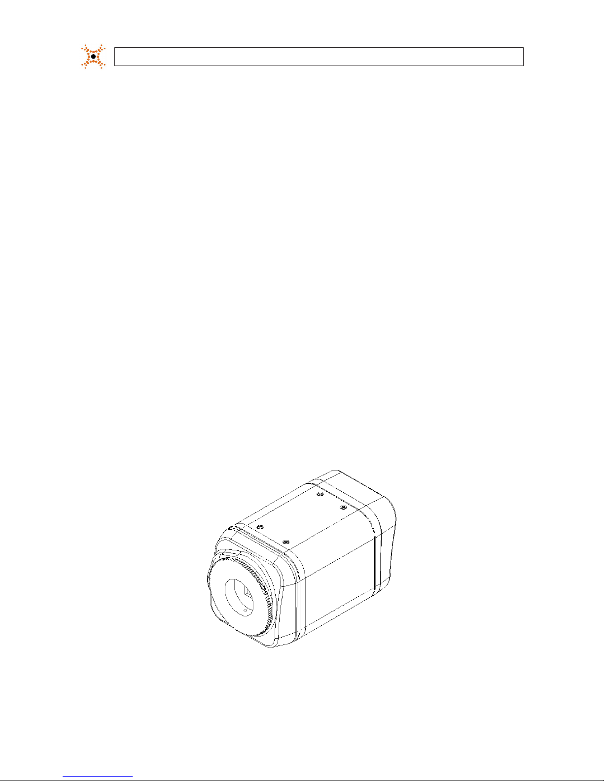
The DIGIOPBlack BLK-IPS103 is a professional, premium-grade, CS-mount box camera designed for indoor use. Lens and mounting
bracket are optional. It features:
• Sony
®
1/3” Super HAD CCD sensor
• High Quality SS-HQ1 full kit chip set
• True Day/Night (ICR) and WDR
• Dual streaming mode
• De-interlacing on DSP
• Unicast/multicast support
• H.264/MPEG-4/MJPEG, 25/30 fps @ D1
• G.711 (µLaw, aLaw)/PCM audio compression
• Analog video for external monitors
• Video motion detection support
• 2-way mono audio support
• RTSP/HTTP protocol support
• 10/100 Base-T Ethernet support
• RS485 support
• USB 2.0 support (external storage, wireless LAN)
• Micro SD card support
• PoE support
• Video Content Analysis features
• OSD support
BLK-IPS103 Camera Body

3H.264 Network IP Camera User Manual
SECTION 1: FEATURES
Analog
video
out
Reset USB
9-pin
terminal
block
DC jack
adapter
cable
connector
Micro
SD card
slot
LAN
4-pin
connector
for Auto Iris
Back connectors and controls
Reset – For restarting the camera, or resetting the camera to its factory default network settings. See Appendix A,
Troubleshooting, for more information.
USB mini-B connector – For a USB storage device or Wi-Fi networking device.
Power adaptor connector (DC 12V) – For use with the DC jack adapter and DC12V power adapter.
Micro SD card slot – SD memory card slot for external storage. DIGIOP memory card is not included.
4-pin connector for auto iris – Connection for lens auto iris control.
Table 1. Pin denitions of 4-pin connector
PIN DC IRIS Lens
1 (upper right) Damp-
2 (upper left) Damp+
3 (lower right) Drive+
4 (lower le ft) Drive-
LAN connector (Ethernet) – For an RJ-45 LAN cable with 10/100 Base-T Ethernet
9-pin terminal block – For DI, DO, audio, and RS-485 communications
Analog Video out – Loop out for local video monitor
4
www.digiop.com
SECTION 1: INSTALLATION AND SETUP
SECTION 2
Installation and Setup
2.1 What’s in the box
Your camera includes the following:
• BLK-IPS103 camera body
• Mounting ring
• Cap for protecting the CCD
• DC power adapter with power plugs for dierent powering sources
• DC jack adapter cable
• 9-pin terminal block
• Quick installation guide
• Mounting adapter and screws for attaching the camera to a mounting bracket
• Hex wrench
• CD mini disk with application software and documentation
2.2 What you need
To install the camera, you will need:
• Phillips #1 or #0 screwdriver
• Mounting bracket
• PC with Microsoft
®
Windows® XP with SP3 or newer, 32- or 64-bit system
• Compatible lens
CAUTION
If using this camera with a high-zoom lens in an environment where the temperature changes more than ±18˚F, optical
blur may occur. For installation with a high-zoom lens, choose an environment where the temperature is stable.
2.3 Mount the camera
1. Determine where the camera will be mounted and record the Media Access Control (MAC) address of the camera. The MAC
address can be found on label on the bottom of the camera. Record the information in the following table.
Location:
MAC addre ss:
5H.264 Network IP Camera User Manual
SECTION 2: INSTALLATION AND SETUP
2. Install the camera mounting bracket using the instructions provided with the bracket.
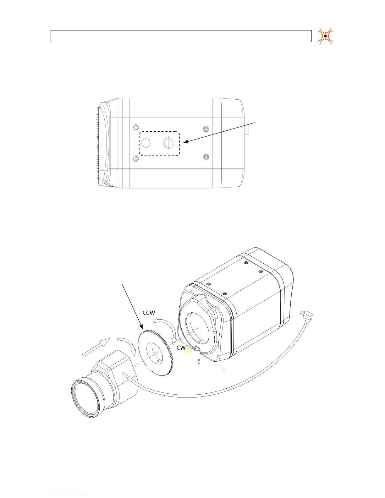
3. Attach the adapter for mounting the camera to side with the label or to the opposite side with the screws provided.
Mounting
adapter
4. Remove the protective cap covering the camera CCD.
5. Attach the lens assembly to the camera by screwing it clockwise onto the camera until it is fully seated. The lens may require
a mounting ring adapter to t onto the camera. Loosen the set screw if necessary.
Mounting ring
Set Screw
Cable for Auto-Iris
6. Tighten the lens set screw with the hex wrench provided.
6
www.digiop.com
SECTION 2: INSTALLATION AND SETUP
7. If the lens assembly has an Auto Iris feature, attach the lens cable to the 4-pin connector on the back of the camera. Pin
denitions are shown in the table below.
8. Attach the camera to the mounting bracket. Use the instructions provided with the bracket.
9. Remove the protective cap from the end of the camera lens, if one is attached.
2.4 Connections
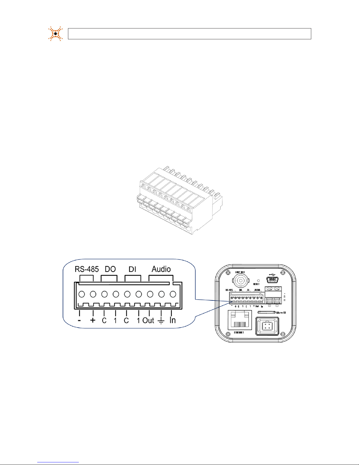
Connections to the camera for audio in and out (microphone and speaker), D/I sensor, alarm, and RS-485 control are made through
the 9-pin terminal block.
9-pin terminal block
Terminal block pin assignments
If the 9-pin terminal block is detached from the camera, plug it into the mating connector on the back of the camera.
7H.264 Network IP Camera User Manual
SECTION 2: INSTALLATION AND SETUP
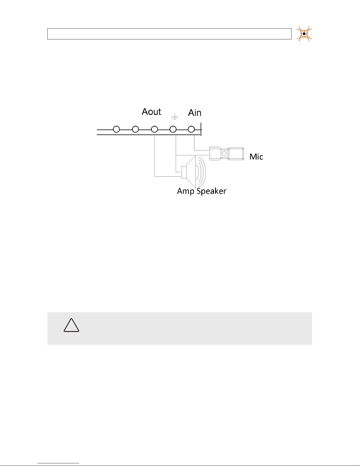
2.4.1 Audio in/out connections
The camera includes an interface for a mono audio input (from a microphone) and a mono audio output (to a speaker). The audio
output is a low level signal that requires an amplied speaker (see Specications). The conguration of the audio wiring (Aout, Ain)
is shown in the following diagram.
Audio in/out wiring schematic
To connect a speaker and/or microphone to the camera, strip 1/4” of insulation from the microphone and speaker wires and insert
them into the terminal block in the pin locations shown in the terminal block gure above. Note that the common (ground) leads of
the microphone and speaker share the same terminal block pin.
2.4.2 Sensor in (DI) connection
The camera provides one channel for sensor input that can be connected to either a voltage type or relay type sensor. For voltage
type sensors, the camera allows a maximum input of 24 V DC, with a 1 V DC threshold (see Specications). The conguration of the
sensor input wiring is illustrated in the following diagrams.
CAUTION
Do not exceed the maximum input voltage or the relay switching rate. Refer to the specications in this
manual for more information.

8
www.digiop.com
SECTION 2: INSTALLATION AND SETUP
Voltage type sensor wiring schematic
Relay type sensor wiring schematic
To connect a sensor to the camera, strip 1/4” of insulation from the sensor wires and insert them into the terminal block in the DI pin
locations shown above. The pin marked “C” in the terminal block is the common (COM) pin.
2.4.3 Alarm out (DO) connection
The camera supports one alarm out connection to relay type device. It provides up to 24 VAC @ 500 mA or 12 V DC @ 1 A. The
conguration of the relay type alarm wiring is illustrated in the diagram below.
CAUTION
Do not exceed the maximum relay rating. Refer to the specications in this manual for more information.
 Loading...