

Observint Technologies BLK-IPE4101 User Manual
4-Channel H.264
Network Video Encoder
User Manual
Product: BLK-IPE4101
Please read this manual before using your encoder, and always follow the instructions for
safety and proper use. Save this manual for future reference.
BLK-IPE4101_PM
8/1/11

ii
www.digiop.com
WARNING
RISK OF ELECTRIC SHOCK. DO NOT OPEN.
To reduce the risk of electric shock, do not
remove cover (or back). No user serviceable
parts inside. Refer servicing to qualied
service personnel.
CAUTION
Operate this encoder only in environments where the temperature or humidity is within the recommended range.
Operation in extreme temperatures or humidity levels may cause electric shock and shorten the life of the product.
LEGAL NOTICE
DIGIOP™ products are designed to meet safety and performance standards with the use of specic DIGIOP™
authorized accessories. DIGIOP™ disclaiSupercirms liability associated with the use of non-DIGIOP™ authorized
accessories.
The recording, transmission, or broadcast of any person’s voice without their consent or a court order is strictly
prohibited by law.
DIGIOP™ makes no representations concerning the legality of certain product applications such as the making,
transmission, or recording of video and/or audio signals of others without their knowledge and/or consent. We
encourage you to check and comply with all applicable local, state, and federal laws and regulations before
engaging in any form of surveillance or any transmission of radio frequencies.
Other trademarks and trade names may be used in this document to refer to either the entities claiming the marks
and names or their products. DIGIOP, Inc. disclaims any proprietary interest in trademarks and trade names other
than its own.
Microsof t, Windows , and Internet E xplorer are either registered trademarks or trademarks of Microsoft Corporation in
the United States and/or other countries.
No part of this document may be reproduced or distributed in any form or by any means without the express written
permission of DIGIOP, Inc.
© 2011 by DIGIOP, Inc. All Rights Reser ved.
3850 Priority Way South Drive, Suite 200, Indianapolis, IN 46240
Sales/Support: 1.877.972.2522

14-Channel H.264 Network Video Encoder
Table of Contents
SECTION 1 Features . . . . . . . . . . . . . . . . . . . . . . . . . . . . . . . . . . . . . . . . . . . . . . . . . . . . . . . . . . . . . . . . . . . . . . . . . . . 2
1.1 Front panel indicators and connectors . . . . . . . . . . . . . . . . . . . . . . . . . . . . . . . . . . . . . . . . . . . . . . . . . . .3
1.2 Back panel connectors . . . . . . . . . . . . . . . . . . . . . . . . . . . . . . . . . . . . . . . . . . . . . . . . . . . . . . . . . . . . . . . .4
SECTION 2 Installation and Setup . . . . . . . . . . . . . . . . . . . . . . . . . . . . . . . . . . . . . . . . . . . . . . . . . . . . . . . . . . . . . . . 5
2.1 What’s in the box . . . . . . . . . . . . . . . . . . . . . . . . . . . . . . . . . . . . . . . . . . . . . . . . . . . . . . . . . . . . . . . . . . . .5
2.2 Tools you need . . . . . . . . . . . . . . . . . . . . . . . . . . . . . . . . . . . . . . . . . . . . . . . . . . . . . . . . . . . . . . . . . . . . . . .5
2.3 Install the encoder . . . . . . . . . . . . . . . . . . . . . . . . . . . . . . . . . . . . . . . . . . . . . . . . . . . . . . . . . . . . . . . . . . .5
2.4 Connections . . . . . . . . . . . . . . . . . . . . . . . . . . . . . . . . . . . . . . . . . . . . . . . . . . . . . . . . . . . . . . . . . . . . . . . . .6
2.4.1 Audio in/out connections (Ain, Aout, channels 1 - 4) . . . . . . . . . . . . . . . . . . . . . . . . . . . . . . . . . .7
2.4.2 Sensor in connection (DI, channels 1 - 4) . . . . . . . . . . . . . . . . . . . . . . . . . . . . . . . . . . . . . . . . . . . .7
2.4.3 Digital out (DO) connection . . . . . . . . . . . . . . . . . . . . . . . . . . . . . . . . . . . . . . . . . . . . . . . . . . . . . . .8
2.4.4 RS-485 device connection. . . . . . . . . . . . . . . . . . . . . . . . . . . . . . . . . . . . . . . . . . . . . . . . . . . . . . . . .9
2.4.5 RS-232C device connection . . . . . . . . . . . . . . . . . . . . . . . . . . . . . . . . . . . . . . . . . . . . . . . . . . . . . .10
2.4.6 LAN, video, and power connections . . . . . . . . . . . . . . . . . . . . . . . . . . . . . . . . . . . . . . . . . . . . . . .10
2.5 Install IPAdmin Tool . . . . . . . . . . . . . . . . . . . . . . . . . . . . . . . . . . . . . . . . . . . . . . . . . . . . . . . . . . . . . . . . .11
2.6 Congure the encoder network settings . . . . . . . . . . . . . . . . . . . . . . . . . . . . . . . . . . . . . . . . . . . . . . . .12
2.6.1 Conguring encoders on networks with DHCP . . . . . . . . . . . . . . . . . . . . . . . . . . . . . . . . . . . . . .12
2.6.2 Conguring encoders on networks without DHCP . . . . . . . . . . . . . . . . . . . . . . . . . . . . . . . . . . .15
2.7 Setup the encoder Basic Conguration . . . . . . . . . . . . . . . . . . . . . . . . . . . . . . . . . . . . . . . . . . . . . . . . .20
2.7.1 Image quality adjustments. . . . . . . . . . . . . . . . . . . . . . . . . . . . . . . . . . . . . . . . . . . . . . . . . . . . . . .24
2.7.2 Setup sensor (DI) and alarm (DO) reporting . . . . . . . . . . . . . . . . . . . . . . . . . . . . . . . . . . . . . . . . .25
2.8 Final installation checks . . . . . . . . . . . . . . . . . . . . . . . . . . . . . . . . . . . . . . . . . . . . . . . . . . . . . . . . . . . . . .27
2.9 Cleaning . . . . . . . . . . . . . . . . . . . . . . . . . . . . . . . . . . . . . . . . . . . . . . . . . . . . . . . . . . . . . . . . . . . . . . . . . . .29
SECTION 3 Specications . . . . . . . . . . . . . . . . . . . . . . . . . . . . . . . . . . . . . . . . . . . . . . . . . . . . . . . . . . . . . . . . . . . . . 30
APPENDIX A Troubleshooting . . . . . . . . . . . . . . . . . . . . . . . . . . . . . . . . . . . . . . . . . . . . . . . . . . . . . . . . . . . . . . . . . . . 32
A.1 Reboot encoder . . . . . . . . . . . . . . . . . . . . . . . . . . . . . . . . . . . . . . . . . . . . . . . . . . . . . . . . . . . . . . . . . . . . .32
A.2 Set encoder to factory default network settings . . . . . . . . . . . . . . . . . . . . . . . . . . . . . . . . . . . . . . . . .32
A.3 Check rmware version . . . . . . . . . . . . . . . . . . . . . . . . . . . . . . . . . . . . . . . . . . . . . . . . . . . . . . . . . . . . . .33
A.4 Support . . . . . . . . . . . . . . . . . . . . . . . . . . . . . . . . . . . . . . . . . . . . . . . . . . . . . . . . . . . . . . . . . . . . . . . . . . .33
APPENDIX B Dimensions . . . . . . . . . . . . . . . . . . . . . . . . . . . . . . . . . . . . . . . . . . . . . . . . . . . . . . . . . . . . . . . . . . . . . . . 34
2
www.digiop.com
SECTION 1: FEATURES
SECTION 1
Features
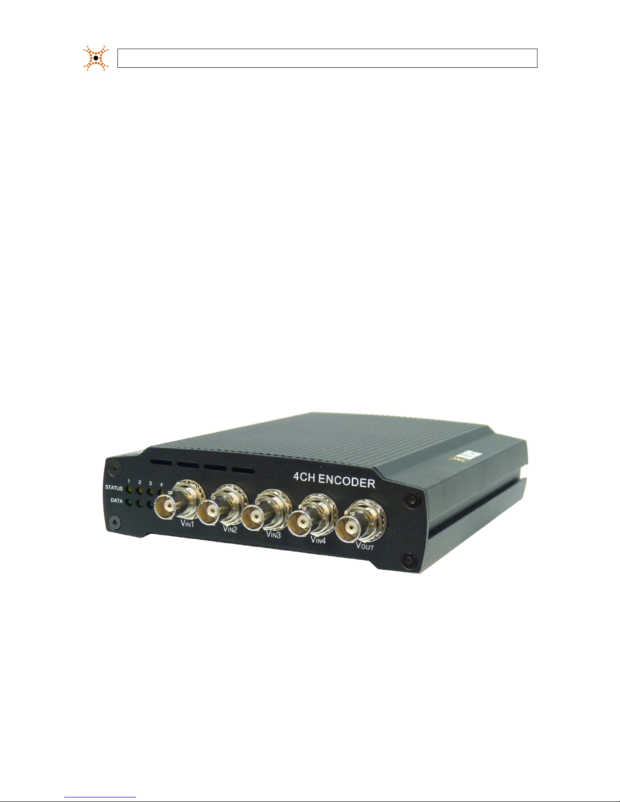
The DIGIOP™ Black BLK-IPE4101 4-channel IP video encoder is a professional, premium-grade, state-of-the-art encoder designed
for indoor installation in networks where exceptional video and audio quality is required with minimal bandwidth and storage
available. Features include:
• 4-channel, H.264, MPEG-4, and MJPEG real-time encoding at D1
• 4 channel audio input, 4 channel audio output support
• Dual streaming mode with dierent codec/resolution/bit rate
• Enhanced deinterlacing on DSP
• Audio compression: G.711
• Embedded intelligent video analytics
• Burnt-in text, video motion detection support
• Remote rmware upgrade over network
• Loop-out video for external monitors
• RS-485/422 serial port for Pan/Tilt/Zoom
• RS-232C serial port
• On Screen Display (OSD) by hardware
BLK-IPE4101 Encoder
34-Channel H.264 Network Video Encoder
SECTION 1: FEATURES
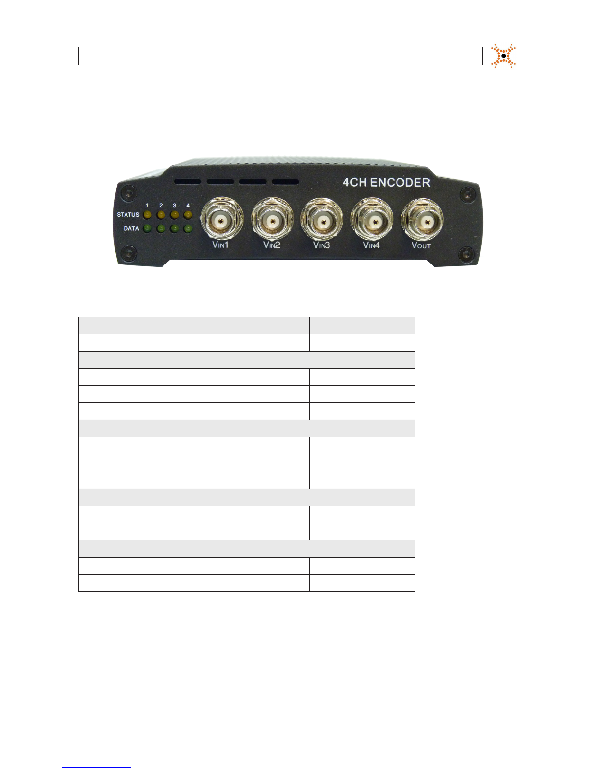
1.1 Front panel indicators and connectors
Status and Data LEDs on the front panel are provided for each IP encoder channel.
Table 1. Status and Data LEDs indications
Status Data Item
OFF OFF Power OFF
System initializ ation
O Blinking Dark Orange In Proce ss
Orange O Normal State
Orange Dar k Orange Abnormal State
Kernel booting up
Orange Gre en In Proce ss
Orange O Normal State
Orange Gre en Abnormal State
Video streaming ser vice
Blinking Green O Nor mal
Green O Abnormal
DSP operation status
Orange blink s at every 1 seco nd O Nor mal
Orange blink s at every 1 seco nd Red High Overload
Vin Video input BNC connector (4)
Vout For loop out of video input
4
www.digiop.com
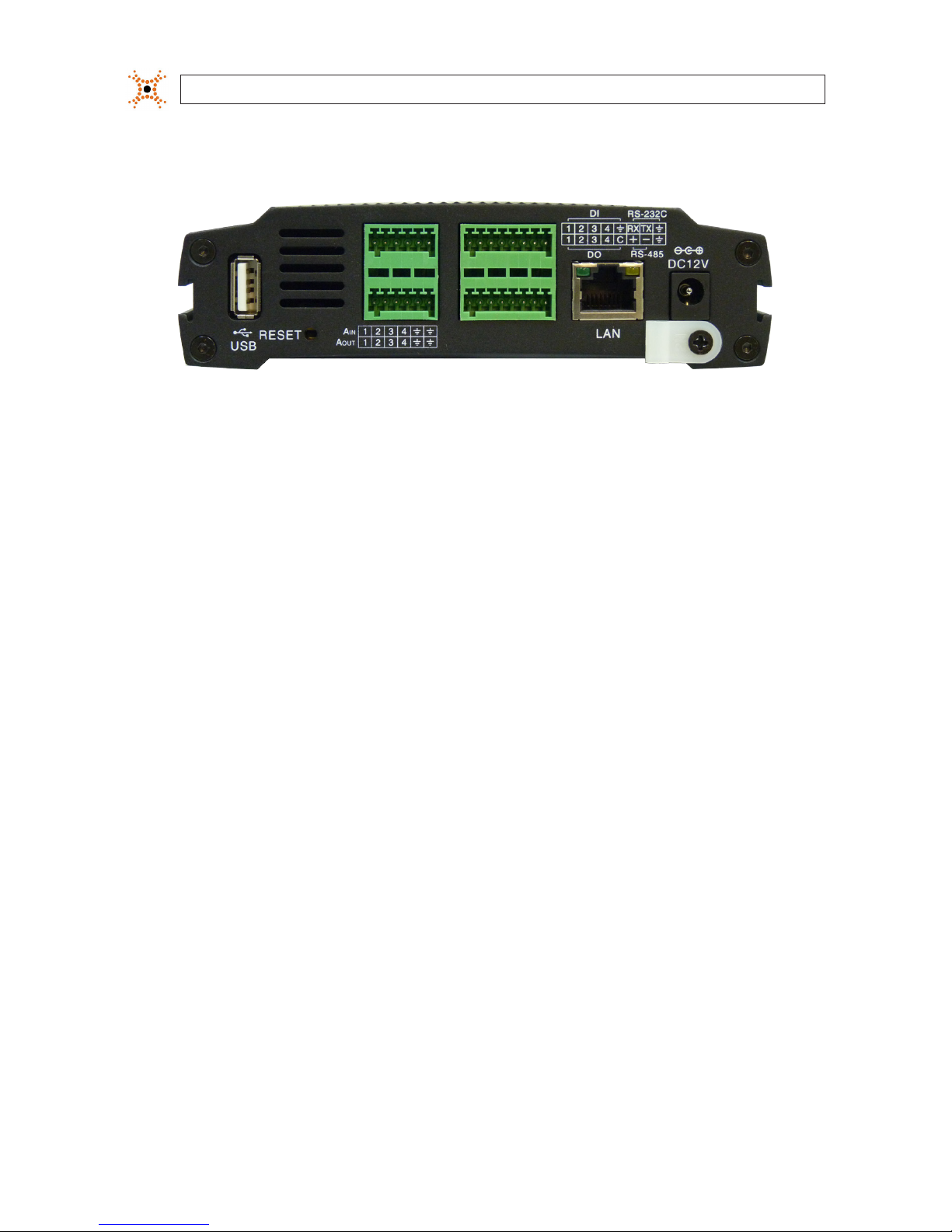
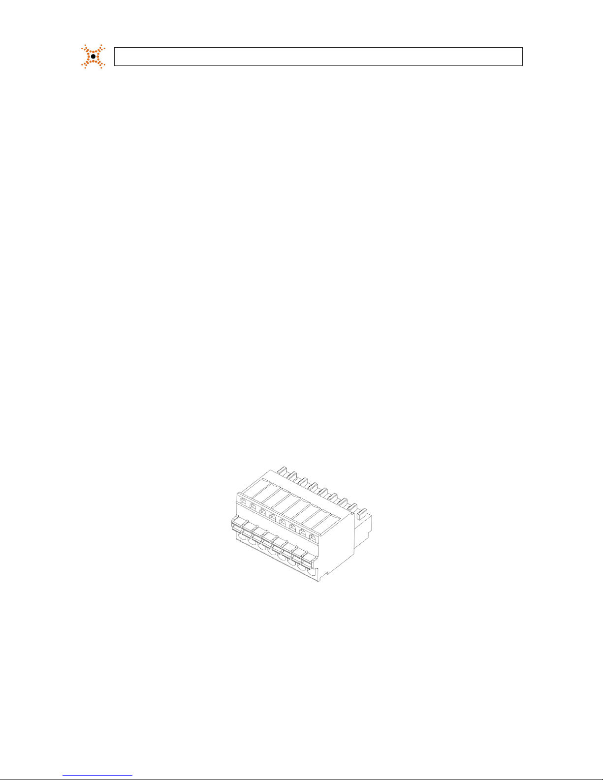
1.2 Back panel connectors
BLK-IPE4101 Encoder back panel
USB Connect to a USB device (or USB hub) for external storage.
Ethernet RJ-45 LAN connector for 10/100Base-T Ethernet.
Pin block Terminal for audio output/input (Ain, A
out
, alarm out (DO), sensor in (DI), and RS-232/RS-485 serial devices
Reset Reset switch for restarting the encoder, or resetting the encoder to factory default settings.
DC12V Power adapter connector.
SECTION 1: FEATURES

54-Channel H.264 Network Video Encoder
SECTION 2: INSTALLATION AND SETUP
SECTION 2
Installation and Setup
2.1 What’s in the box
Your encoder includes the following:
• BLK-IPE4101 encoder
• 12 V DC power adapter
• 6-pin terminal blocks (2)
• 8-pin terminal blocks (2)
• Hardware installation kit including mounting brackets (2), screws (4), and wall inserts (2)
• CD mini disk with application software, software manual, and encoder user manual (this document)
2.2 Tools you need
To install the encoder, you will need:
• Phillips #2 screwdriver
• Drill 1/4” drill bit
• PC with Microsoft
®
Windows® XP SP3 or newer, 32- or 64-bit system
2.3 Install the encoder
1. Determine where the encoder will be mounted and record the 4 (one for each IP channel) Media Access Control (MAC)
address of the encoder. The MAC address can be found on a label on the underside of the encoder and are listed as channel 1
(top) to channel 4 (bottom). Record the information in the following table.
Location:
Chann el 1 MAC address:
Chann el 2 MAC address:
Chann el 3 MAC address:
Chann el 4 MAC address:
NOTE
The Channel 1 MAC address is associated with the Vin1 analog input, Channel 2 MAC address is associated with the
Vin2 analog input, etc.
6
www.digiop.com
SECTION 2: INSTALLATION AND SETUP
2. Slide the mounting brackets provided in the hardware kit into the slots on the side of the encoder.
3. Do one of the following:
— If the mounting surface is a hard material, use the 1/2” self-tapping mounting screws provided in the hardware kit to
secure the encoder to the surface.
OR
— If the mounting surface is a soft material:
i. Using the encoder with the mounting brackets as a template, mark the location of the mounting screw holes.
ii. Drill 1/4” holes in the location of the mounting screw holes for the wall inserts provided in the hardware kit.
iii. Tap the wall inserts into the holes until they are ush with the surface.
iv. Use the 1-1/8” screws provided in the hardware kit to secure the encoder to the surface.
4. Connect an analog signal source (camera video) to the Vin BNC connector on the front of the encoder.
2.4 Connections
Connections to the encoder for audio in and out (microphone Ain and speaker, A
out
), sensor in (DI), alarm (DO), video out BNC,
RS-232C, and RS-485 control are made through two 8-pin terminal blocks and two 6-pin terminal blocks. The terminal blocks may
be detached from the encoder. Plug the four blocks into the connectors on the back of the encoder.
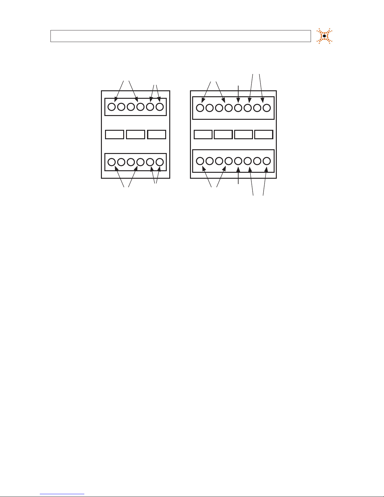
8-pin terminal block
74-Channel H.264 Network Video Encoder
SECTION 2: INSTALLATION AND SETUP
Ain
Grounds
Ground
Common
Aout 1 - 4 DO 1 - 4
Aout
Grounds
Ain 1 - 4 DI 1 - 4
RS-232
TX, RX, Gnd
RS-485
DATA+, DATA-, Gnd
Terminal block pin assignments
2.4.1 Audio in/out connections (Ain, Aout, channels 1 - 4)
The encoder includes an interface for a mono audio input (from a microphone) and a mono audio output (to a speaker) for each
channel. The audio output is a low level signal that requires an amplied speaker (see Specications).
To connect a speaker and/or microphone to the encoder:
1. Route speaker and/or microphone wiring to the encoder.
2. Strip 1/4” of insulation from the wires speaker signal and ground wires and insert them into the lower 6-pin terminal block
on the Aout and Aout Ground pins, respectively.
3. Strip 1/4” of insulation from the microphone signal and ground wires and insert them into the upper 6-pin terminal block on
the Ain and Ain Ground pins, respectively.
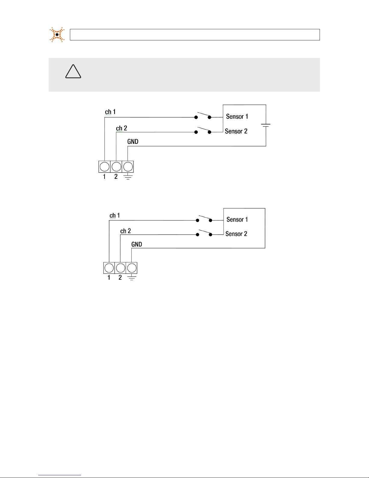
2.4.2 Sensor in connection (DI, channels 1 - 4)
The encoder provides four input channels for sensors, one for each channel. The sensors can be either all voltage or all relay type
sensors. For voltage type sensors, see Specications for allowable voltage levels. The conguration of each sensor input wiring is
illustrated in the diagrams below.
8
www.digiop.com
SECTION 2: INSTALLATION AND SETUP
CAUTION
Do not exceed the maximum input voltage or the relay switching rate. Refer to specications in this manual
for more information.
Voltage type sensor wiring schematic
Relay type sensor wiring schematic
To connect a sensor to the encoder:
1. Route sensor wiring to the encoder.
2. Strip 1/4” of insulation from one sensor’s sense and ground wires and insert them into the upper 8-pin terminal block in the
DI (for channel 1, 2, 3, or 4) and DI Ground pin locations, respectively.
3. Strip 1/4” of insulation from another sensor’s sense and ground wires and insert them into the upper 8-pin terminal block in
the Ground pin locations, respectively.
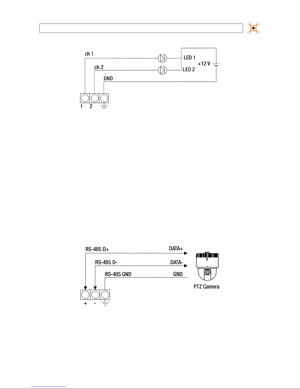
2.4.3 Digital out (DO) connection
The encoder supports up to four digital out connections to reporting devices in the conguration shown in the schematic below.
94-Channel H.264 Network Video Encoder
SECTION 2: INSTALLATION AND SETUP
Digital out wiring schematic
To connect digital out reporting device to the encoder:
1. Route leads from the digital out devices to the encoder.
2. Strip 1/4” of insulation from one device’s signal and ground wires and insert them into the lower terminal block in the DO ch
1 and DO GND pin locations, respectively.
3. Strip 1/4” of insulation from another device’s signal and ground wires and insert them into the lower terminal block in the DO
ch 2 and DO GND pin locations, respectively.
2.4.4 RS-485 device connection
The encoder provides one RS-485 interface connection. The wiring signal polarity and ground to the lower terminal block are
shown in the schematic below.
RS-485 device wiring schematic
To connect an RS-485 device wiring to the encoder:
1. Route wiring from the RS-485 device interface to the encoder.
 Loading...