

Observint Technologies BLK-IPD103 User Manual

Indoor/Outdoor Mini-Dome
IP Camera User Manual
Product: BLK-IPD103
Please read this manual before using your camera, and always follow the instructions for
safety and proper use. Save this manual for future reference.
BLK-IPD103_CM

ii
www.digiop.com
CAUTION
Do not operate this camera in environments where the temperatures or humidity is outside the recommended range.
Doing so my cause electric shock and shorten the life of the product.
LEGAL NOTICE
DIGIOP products are designed to meet safety and performance standards with the use of specic DIGIOP
authorized accessories. DIGIOP disclaims liability associated with the use of non-DIGIOP authorized accessories.
The recording, transmission, or broadcast of any person’s voice without their consent or a court order is strictly
prohibited by law.
DIGIOP makes no representations concerning the legality of certain product applications such as the making,
transmission, or recording of video and/or audio signals of others without their knowledge and/or consent. We
encourage you to check and comply with all applicable local, state, and federal laws and regulations before
engaging in any form of surveillance or any transmission of radio frequencies.
Microsof t, Windows, and Interne t Explorer are either registered trademarks or trademarks of Microsoft Corporation in
the United States and/or other countries. OmniVision is registered trademarks of OmniVision Technologies, Inc.
Other trademarks and trade names may be used in this document to refer to either the entities claiming the marks
and names or their products. DIGIOP, Inc. disclaims any proprietary interest in trademarks and trade names other
than its own.
No part of this document may be reproduced or distributed in any form or by any means without the express written
permission of DIGIOP, Inc.
© 2011 DIGIOP, Inc. All Rights Reserved.
3850 Priority Way South Drive, Suite 200, Indianapolis, IN 46240
Sales/Support: 1.877.972.2522

1Indoor/Outdoor Mini-Dome IP Camera
Table of Contents
SECTION 1 Features . . . . . . . . . . . . . . . . . . . . . . . . . . . . . . . . . . . . . . . . . . . . . . . . . . . . . . . . . . . . . . . . . . . . . . . . . . . 2
SECTION 2 Installation and Setup . . . . . . . . . . . . . . . . . . . . . . . . . . . . . . . . . . . . . . . . . . . . . . . . . . . . . . . . . . . . . . . 3
2.1 What’s in the box . . . . . . . . . . . . . . . . . . . . . . . . . . . . . . . . . . . . . . . . . . . . . . . . . . . . . . . . . . . . . . . . . . . .3
2.2 Tools you need . . . . . . . . . . . . . . . . . . . . . . . . . . . . . . . . . . . . . . . . . . . . . . . . . . . . . . . . . . . . . . . . . . . . . . .3
2.3 Mount the camera . . . . . . . . . . . . . . . . . . . . . . . . . . . . . . . . . . . . . . . . . . . . . . . . . . . . . . . . . . . . . . . . . . .3
2.4 Connections . . . . . . . . . . . . . . . . . . . . . . . . . . . . . . . . . . . . . . . . . . . . . . . . . . . . . . . . . . . . . . . . . . . . . . . . .4
2.5 Install IPAdmin Tool . . . . . . . . . . . . . . . . . . . . . . . . . . . . . . . . . . . . . . . . . . . . . . . . . . . . . . . . . . . . . . . . . .5
2.6 Congure the camera network settings . . . . . . . . . . . . . . . . . . . . . . . . . . . . . . . . . . . . . . . . . . . . . . . . . .6
2.6.1 Conguring cameras on networks with DHCP . . . . . . . . . . . . . . . . . . . . . . . . . . . . . . . . . . . . . . . .6
2.6.2 Conguring cameras on networks without DHCP . . . . . . . . . . . . . . . . . . . . . . . . . . . . . . . . . . . . .8
2.7 Setup the camera Basic Conguration . . . . . . . . . . . . . . . . . . . . . . . . . . . . . . . . . . . . . . . . . . . . . . . . . .13
2.8 Aim, focus, and image quality adjustment . . . . . . . . . . . . . . . . . . . . . . . . . . . . . . . . . . . . . . . . . . . . . .16
2.8.1 Aim . . . . . . . . . . . . . . . . . . . . . . . . . . . . . . . . . . . . . . . . . . . . . . . . . . . . . . . . . . . . . . . . . . . . . . . . . .16
2.8.2 Adjust focus and zoom . . . . . . . . . . . . . . . . . . . . . . . . . . . . . . . . . . . . . . . . . . . . . . . . . . . . . . . . . .17
2.8.3 Image quality adjustments. . . . . . . . . . . . . . . . . . . . . . . . . . . . . . . . . . . . . . . . . . . . . . . . . . . . . . .18
2.9 Speaker/microphone setup . . . . . . . . . . . . . . . . . . . . . . . . . . . . . . . . . . . . . . . . . . . . . . . . . . . . . . . . . . .19
2.10 Cleaning . . . . . . . . . . . . . . . . . . . . . . . . . . . . . . . . . . . . . . . . . . . . . . . . . . . . . . . . . . . . . . . . . . . . . . . . . . .21
SECTION 3 Specications . . . . . . . . . . . . . . . . . . . . . . . . . . . . . . . . . . . . . . . . . . . . . . . . . . . . . . . . . . . . . . . . . . . . . 22
APPENDIX A Troubleshooting . . . . . . . . . . . . . . . . . . . . . . . . . . . . . . . . . . . . . . . . . . . . . . . . . . . . . . . . . . . . . . . . . . . 24
A.1 Reboot camera . . . . . . . . . . . . . . . . . . . . . . . . . . . . . . . . . . . . . . . . . . . . . . . . . . . . . . . . . . . . . . . . . . . . .24
A.2 Set camera to factory default network settings . . . . . . . . . . . . . . . . . . . . . . . . . . . . . . . . . . . . . . . . . .24
A.3 Checking your Firmware . . . . . . . . . . . . . . . . . . . . . . . . . . . . . . . . . . . . . . . . . . . . . . . . . . . . . . . . . . . . .25
A.4 Support . . . . . . . . . . . . . . . . . . . . . . . . . . . . . . . . . . . . . . . . . . . . . . . . . . . . . . . . . . . . . . . . . . . . . . . . . . .25
APPENDIX B Dimensions . . . . . . . . . . . . . . . . . . . . . . . . . . . . . . . . . . . . . . . . . . . . . . . . . . . . . . . . . . . . . . . . . . . . . . . 26
APPENDIX C Power over Ethernet . . . . . . . . . . . . . . . . . . . . . . . . . . . . . . . . . . . . . . . . . . . . . . . . . . . . . . . . . . . . . . . . 28
C.1 PoE compatibility . . . . . . . . . . . . . . . . . . . . . . . . . . . . . . . . . . . . . . . . . . . . . . . . . . . . . . . . . . . . . . . . . . .28
C.2 Power classication . . . . . . . . . . . . . . . . . . . . . . . . . . . . . . . . . . . . . . . . . . . . . . . . . . . . . . . . . . . . . . . . .28
2
www.digiop.com
SECTION 1: FEATURES
SECTION 1
Features
The DIGIOP Black BLK-IPD103 is a professional, premium-grade mini-dome IP camera designed for indoor or outdoor installation. It
features:
• Gimbal mount
• OmniVision® 1/3.6” Super CMOS CCD sensor
• Dual streaming mode with dierent CODECs, resolution, bit rate, etc.
• De-interlacing on DSP
• Supports burnt-in text, unicast/multicast
• Video compression: H.264/MPEG-4/MJPEG 30 fps @ D1
• Audio compression: G.711 (µLaw, aLaw)/PCM
• Supports motion detection, 2-way mono audio support, analog video out for external monitor
• Supports 10/100 Base-T Ethernet, RTSP/ HTTP protocol support
• PoE support
• OSD support
• Software development kit (SDK) available
• Video Content Analysis presence, surveillance (optional)
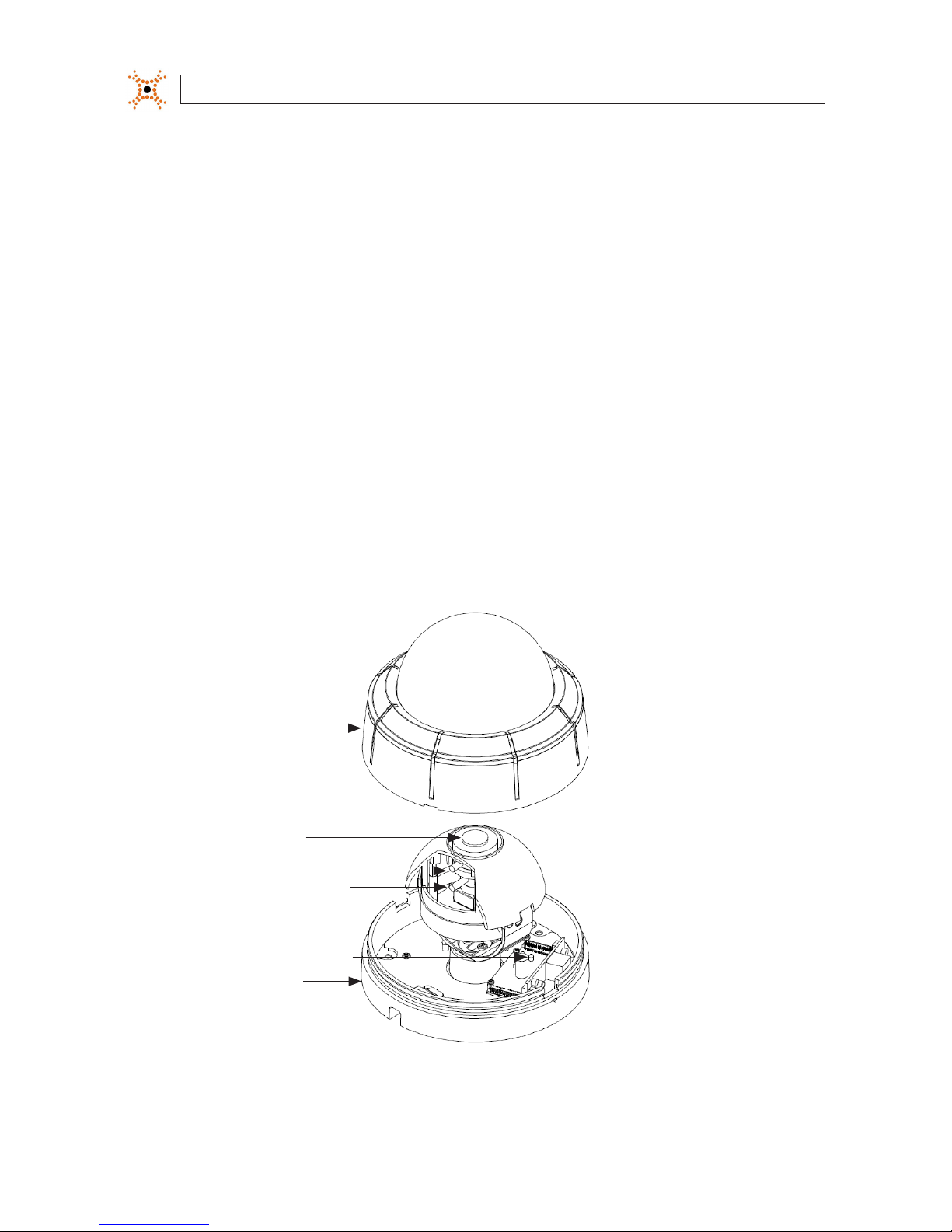
Cover
Base
Focus Puller
Zoom Puller
Reset Button
Lens
BLK-IPD103 camera without the housing
3Indoor/Outdoor Mini-Dome IP Camera
SECTION 2: INSTALLATION AND SETUP
SECTION 2
Installation and Setup
2.1 What’s in the box
Your dome camera includes the following:
• BLK-IPD103 camera
• DC power adapter with power plugs for dierent powering sources
• Hardware installation kit with a 3 screws and wall inserts
• Camera cover opener tool
• CD with IPAdminTool software and documentation
• Quick Installation Guide
2.2 Tools you need
To install the camera, you will need:
• Phillips #2 screwdriver
• PC with Microsoft
®
Windows® XP SP3 or newer, 32- or 64-bit system
Depending on how the camera is mounted, you may also need:
• Hammer
• Drill with bits for drilling mounting holes
• 1-3/8” hole saw
2.3 Mount the camera
1. Determine where the camera will be mounted and record the Media Access Control (MAC) address of the camera. The MAC
address can be found on the label on the base of the camera. Record the information in the following table.
Location:
MAC address:
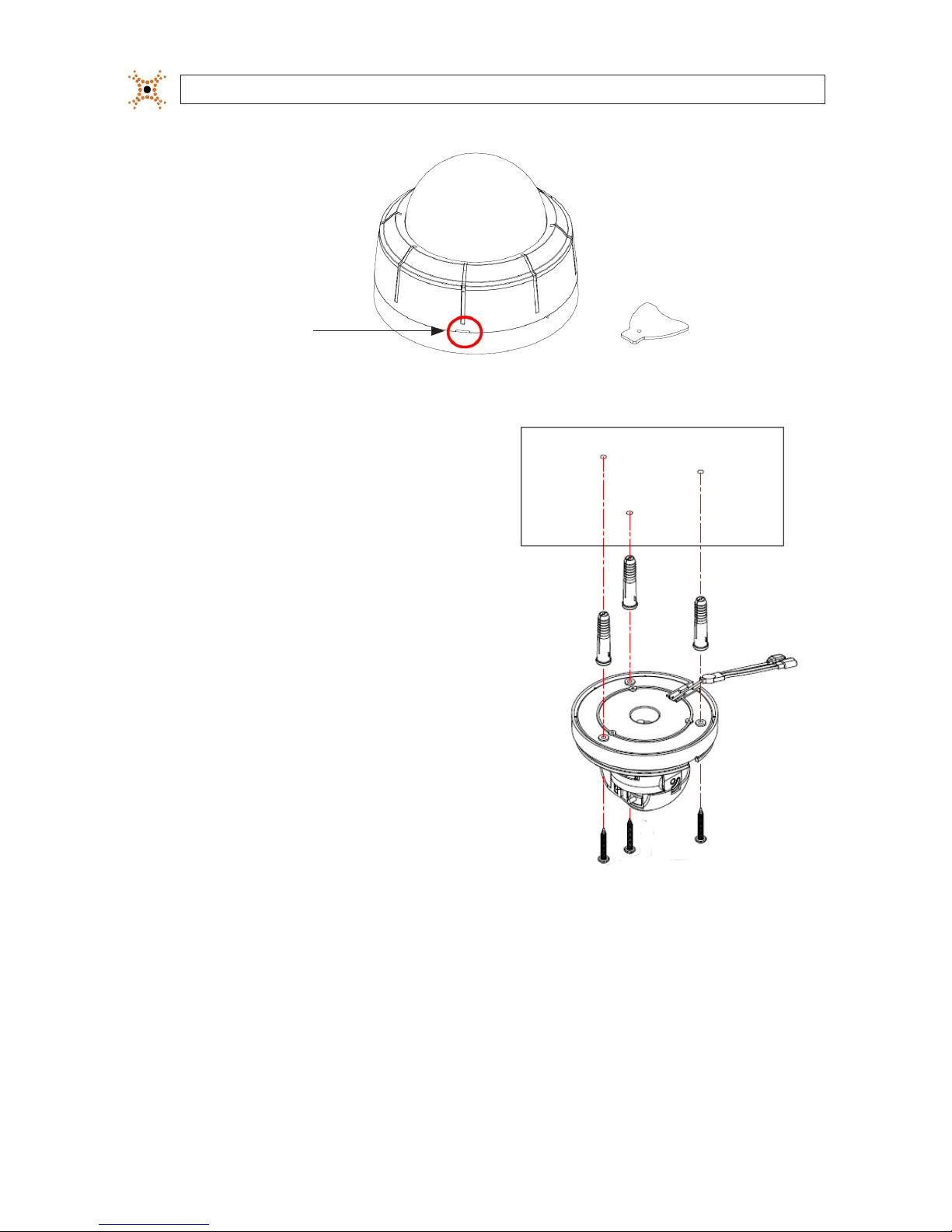
2. Separate the camera cover from the camera base. Insert the cover removal tool into the slot on the side of the camera, then
gently twist the tool to pry o the cover.
4
www.digiop.com
SECTION 2: INSTALLATION AND SETUP
Cover
opener
Slot
Camera dome removal
3. Using the base as a template, mark the location of the three
mounting screw holes.
4. Drill mounting screw holes into the mounting surface:
— If the mounting surface is a soft material, such as
a drywall, drill and install drywall inserts for the
mounting screws.
OR
— If the mounting surface is a very soft material, such as
ceiling tile, place a wood block behind the tile and drill
holes for mounting screws long enough to secure the
base to the block.
OR
— If mounting the camera on a hard surface, such as
wood, drill the mounting screw holes into the surface
before attaching the camera.
5. Determine the drop cable routing. If routing the cable will be
routed hole through the mounting surface, drill a 3/4” hole for
the cable.
Drop Cable
Wall
Inserts
Mounting
Screws
6. Route the drop cable the mounting surface (if necessary), then attach the camera base to the mounting surface.
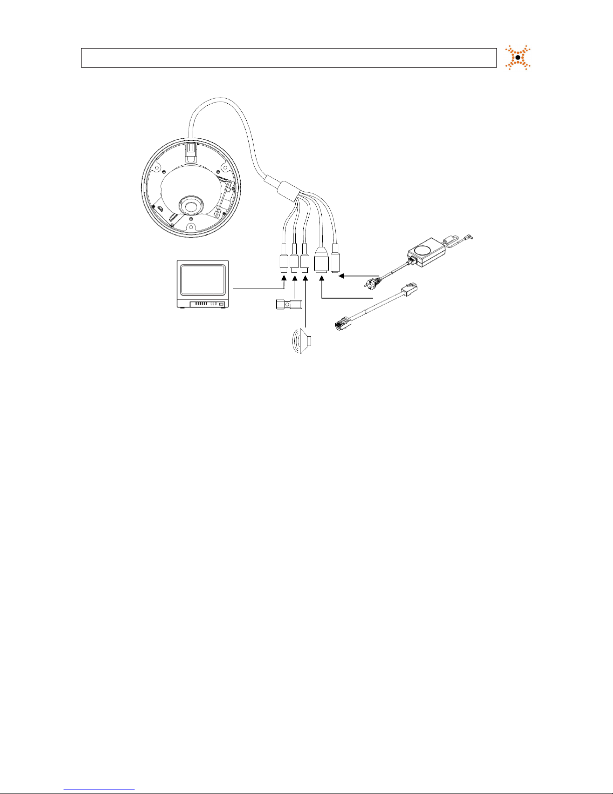
2.4 Connections
Connections to the camera for video out, audio in and out (microphone and speaker), power, and LAN are made at the drop cable.
5Indoor/Outdoor Mini-Dome IP Camera
SECTION 2: INSTALLATION AND SETUP
Monitor
Speaker
Mic
LAN
Drop
Drop
Cable
Power
Adapter
Camera connections
1. Attach a monitor, speaker, and microphone to the appropriate camera drop cable connector as needed.
2. Attach a LAN drop cable to the RJ45 camera drop cable connector. If the camera is powered through the LAN cable, DO NOT
apply power to the camera at this time.
3. Connect a 12 VDC power adapter to the power cable connector on the drop cable. If the LAN drop cable carries Power over
Ethernet (PoE), this connection is optional. DO NOT apply power to the camera at this time. See Appendix C for more
information.
2.5 Install IPAdmin Tool
The IPAdmin Tool, included on the CD mini disk, is a utility that will discover cameras installed on your network and enable you
to perform the initial network setup for each camera. After a camera is setup on the network, the Microsoft Internet Explorer®
web browser can be used to see video from the camera, set the camera’s password, date and time, nalize camera hardware
adjustments, and congure the camera for functional requirements.
The IPAdminTool can be loaded on a Microsoft Windows XP, Vista or Windows 7 operating system (32- or 64-bit). To use this utility
for the initial setup of your camera, your computer must be connected to the same network subnet as your camera.
At a computer on the same LAN (subnet) where your cameras will be installed, do the following:

6
www.digiop.com
SECTION 2: INSTALLATION AND SETUP
1. Insert the CD mini disk provided with your camera into your computer’s CD ROM drive and open the CD in a Windows
Explorer window.
2. Find the IPAdminTool directory on the CD.
3. Copy the IPAdminTool directory with its contents to your computer hard drive.
2.6 Congure the camera network settings
Devices attached to a Local Area Network (LAN) are each assigned a unique address (IP address) that they use when sending
messages with each other. No two devices on a single Ethernet network can have the same IP address. Otherwise, addressing
conicts will occur.
When your IP camera is attached to a network and initially powered on, it attempts acquire compatible network settings from
a DHCP server. If it cannot nd a DHCP server, it congures itself with the following static IP address, subnet mask, and gateway
setting, which may or may not be compatible with other devices on the network.
IP address: 192.168.0.100
Subnet mask: 255.255.255.0
Gateway: 192.168.0.1
Whether it acquires a dynamic (changeable) IP address and other network settings from a DHCP server, or uses the default static
(xed, unchanging) settings, your camera must be congured with static network settings that are compatible with the network
conguration. Additionally, if DHCP is not used on your network, DIGIOP Black cameras must be installed on the network and
congured with new network settings one at a time to avoid addressing conicts.
Use the following procedure to setup and apply compatible, static, network settings for your camera. If connecting your camera to a
large enterprise network, consult with your network administrator for network settings before attaching the camera to the LAN to
ensure that your camera won’t conict with other devices. Your network administrator should also setup WAN (Internet) access to
the camera, if that is needed.
If you encounter a problem and need to contact Technical Support, rst complete the chart in Table 1 about your computer (PC) and
camera network settings, if possible. Support will need this information to provide assistance.
2.6.1 Conguring cameras on networks with DHCP
In networks with a DHCP server, the IP camera will acquire dynamic (changeable) network settings when it is initially powered on.
These dynamic settings can easily be converted to static settings, or changed to other static settings that are also compatible with
your network.
7Indoor/Outdoor Mini-Dome IP Camera
SECTION 2: INSTALLATION AND SETUP
1. Connect your camera to the LAN, then power on the camera.
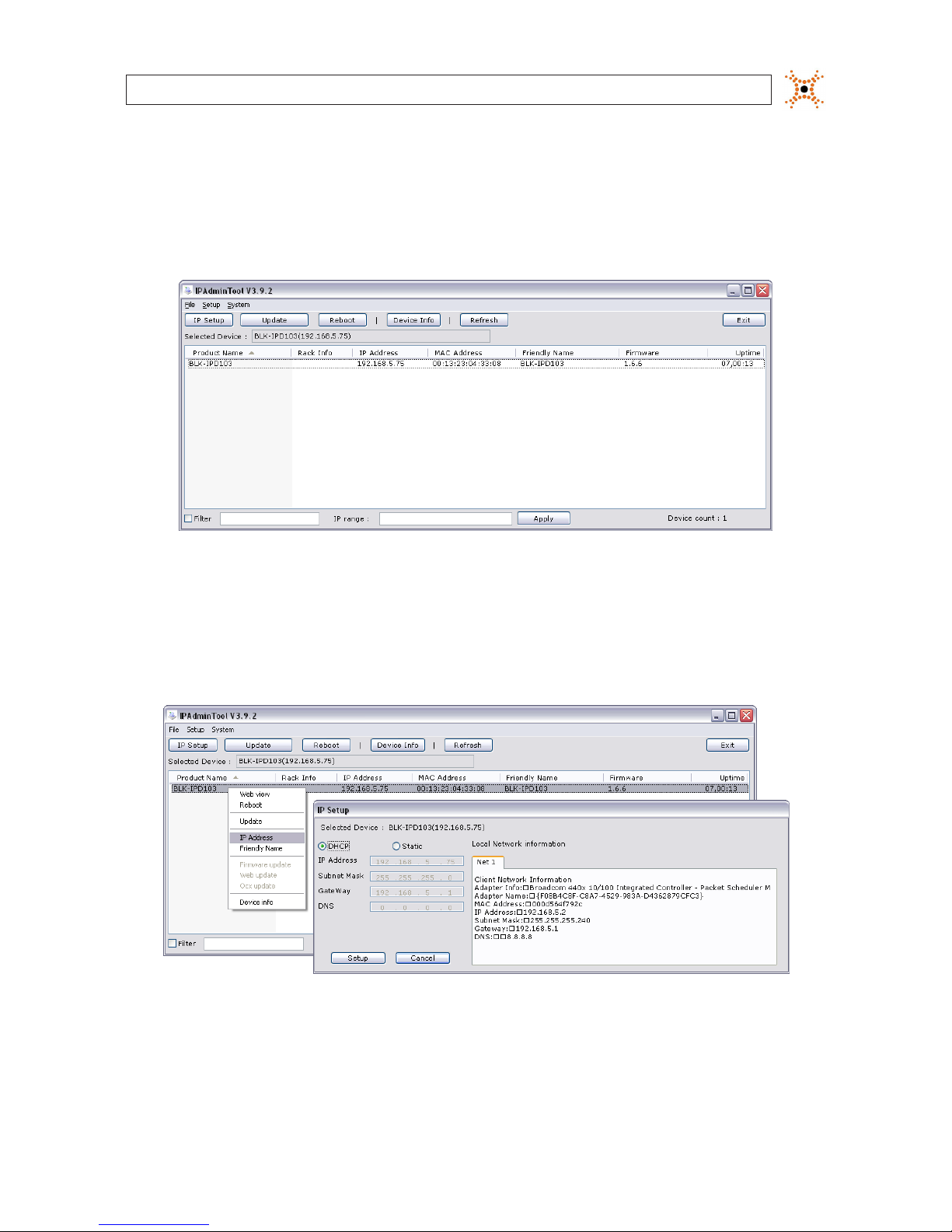
2. Open the IPAdminTool directory on your computer, then double click the le IPAdminTool.exe to start the application.
When the IPAdmin Tool starts, it will discover all the IP devices it supports that exist on the network. The discovery process
may take a few minutes.
Check the list of IP devices found by IPAdmin Tool. You can identify your camera by the MAC address. If the camera was not
found, click the Refresh button every minute until your camera appears in the list.
3. In the IPAdmin Tool device list, use the camera’s MAC Address to nd the camera you are installing. After nding the camera,
right click the entry, then select IP Address from the drop-down list. An IP Setup window will open.
4. In the IP Setup window, click the Static option bullet to select this option.
 Loading...