

Observint Technologies BLK-HDPTZ12 User Manual
BLK-HDPTZ12 2 Megapixel 12x
HD-SDI / HDcctv PTZ Dome Camera
User Manual
Product: BLK-HDPTZ12
Please read this manual before using your camera, and always follow the instructions
for safety and proper use. Save this manual for future reference.
BLK-HDPTZ12_CM
1/21/13

ii
REGULATORY NOTICE
This device complies with Part 15 of the FCC Rules. Operation is subject to the following two conditions;
1. This device may not cause harmful interference.
2. This device must accept any interference received, including interference that may cause undesired
operation.
This equipment has been tested and found to comply with the limits for a Class A digital device, pursuant to part
15 of the FCC Rules. These limits are designed to provide reasonable protection against harmful interference
when the equipment is operated in a commercial environment. This equipment generates, uses, and can radiate
radio frequency energy and, if not installed and used in accordance with the instruction manual, may cause
harmful interference to radio communications. Operation of this equipment in a residential area is likely to cause
harmful interference in which case the user will be required to correct the interference at his own expense.”
LEGAL NOTICE
Observi nt Technologie s (Observint) products are designed to meet safety and performance standards with the use
of specic Obs ervint authorized accessories. O bservint disclaims liability associated with the use of non-O bservint
authorized accessories.
The recording, transmission, or broadcast of any person’s voice without their consent or a court order is strictly
prohibited by law.
Observi nt makes no representations concerning the legality of certain product applications such as the making,
transmission, or recording of video and/or audio signals of others without their knowledge and/or consent. We
encourage you to check and comply with all applicable local, state, and federal laws and regulations before
engaging in any form of surveillance or any transmission of radio frequencies.
Other trademarks and trade names may be used in this document to refer to either the entities claiming the marks
and names or their products. Obser vint disclaims any proprietary interest in trademarks and trade names other than
its own.
No part of this document may be reproduced or distributed in any form or by any means without the express written
permission of Obser vint.
© 2013 by Observint Technologies. All Rights Reserved.
11000 N. Mopac Expressway, Building 300, Austin, TX 78759
For Sales and Support, please contact your distributor.

iii2MP 12X PTZ HD-SDI/HDcctv Dome Camera
Table of Contents
Precautions . . . . . . . . . . . . . . . . . . . . . . . . . . . . . . . . . . . . . . . . . . . . . . . . . . . . . . . . . . . . . . . . . . . . . . . . . . . . . . v
SECTION 1 Introduction . . . . . . . . . . . . . . . . . . . . . . . . . . . . . . . . . . . . . . . . . . . . . . . . . . . . . . . . . . . . . . . . . . . . . . . 1
1.1 What’s in the box . . . . . . . . . . . . . . . . . . . . . . . . . . . . . . . . . . . . . . . . . . . . . . . . . . . . . . . . . . . . . . . . . . . .1
1.2 System conguration . . . . . . . . . . . . . . . . . . . . . . . . . . . . . . . . . . . . . . . . . . . . . . . . . . . . . . . . . . . . . . . . .2
1.2.1 RS-485 network termination . . . . . . . . . . . . . . . . . . . . . . . . . . . . . . . . . . . . . . . . . . . . . . . . . . . . . .3
SECTION 2 Installation . . . . . . . . . . . . . . . . . . . . . . . . . . . . . . . . . . . . . . . . . . . . . . . . . . . . . . . . . . . . . . . . . . . . . . . . 4
2.1 General Guidelines . . . . . . . . . . . . . . . . . . . . . . . . . . . . . . . . . . . . . . . . . . . . . . . . . . . . . . . . . . . . . . . . . . .4
2.2 Install the mounting bracket . . . . . . . . . . . . . . . . . . . . . . . . . . . . . . . . . . . . . . . . . . . . . . . . . . . . . . . . . .4
2.3 Set the camera hardware conguration switches . . . . . . . . . . . . . . . . . . . . . . . . . . . . . . . . . . . . . . . . .5
2.4 Attach the camera module to the mounting bracket . . . . . . . . . . . . . . . . . . . . . . . . . . . . . . . . . . . . . . .8
SECTION 3 Software Setup - Operating Guide . . . . . . . . . . . . . . . . . . . . . . . . . . . . . . . . . . . . . . . . . . . . . . . . . . . . 12
3.1 Getting Started . . . . . . . . . . . . . . . . . . . . . . . . . . . . . . . . . . . . . . . . . . . . . . . . . . . . . . . . . . . . . . . . . . . . .12
3.1.1 Accessing the MAIN MENU [95] + [Preset] / [Menu] . . . . . . . . . . . . . . . . . . . . . . . . . . . . . . . . .13
3.1.2 Editing TITLE . . . . . . . . . . . . . . . . . . . . . . . . . . . . . . . . . . . . . . . . . . . . . . . . . . . . . . . . . . . . . . . . . .13
3.2 MAIN MENU . . . . . . . . . . . . . . . . . . . . . . . . . . . . . . . . . . . . . . . . . . . . . . . . . . . . . . . . . . . . . . . . . . . . . . . .14
3.3 SYSTEM SETUP menu . . . . . . . . . . . . . . . . . . . . . . . . . . . . . . . . . . . . . . . . . . . . . . . . . . . . . . . . . . . . . . . .14
3.3.1 INFO – System Information . . . . . . . . . . . . . . . . . . . . . . . . . . . . . . . . . . . . . . . . . . . . . . . . . . . . . .15
3.3.2 REBOOT menu . . . . . . . . . . . . . . . . . . . . . . . . . . . . . . . . . . . . . . . . . . . . . . . . . . . . . . . . . . . . . . . . . .15
3.3.3 INITIALIZE menu . . . . . . . . . . . . . . . . . . . . . . . . . . . . . . . . . . . . . . . . . . . . . . . . . . . . . . . . . . . . . . . .16
3.3.4 Entering a PASSWORD . . . . . . . . . . . . . . . . . . . . . . . . . . . . . . . . . . . . . . . . . . . . . . . . . . . . . . . . . . .17
3.4 DISPLAY SETUP Menu . . . . . . . . . . . . . . . . . . . . . . . . . . . . . . . . . . . . . . . . . . . . . . . . . . . . . . . . . . . . . . . .17
3.4.1 LANGUAGE menu . . . . . . . . . . . . . . . . . . . . . . . . . . . . . . . . . . . . . . . . . . . . . . . . . . . . . . . . . . . . . . .18
3.4.2 OSD SETUP menu . . . . . . . . . . . . . . . . . . . . . . . . . . . . . . . . . . . . . . . . . . . . . . . . . . . . . . . . . . . . . . .18
3.4.3 PRIVACY ZONE SETUP menu . . . . . . . . . . . . . . . . . . . . . . . . . . . . . . . . . . . . . . . . . . . . . . . . . . . . . .19
3.4.4 IMAGE SETUP menu . . . . . . . . . . . . . . . . . . . . . . . . . . . . . . . . . . . . . . . . . . . . . . . . . . . . . . . . . . . . .20
3.4.5 MOTION DETECTION (MD) menu . . . . . . . . . . . . . . . . . . . . . . . . . . . . . . . . . . . . . . . . . . . . . . . . . .20
3.4.6 RESOLUTION SETUP menu . . . . . . . . . . . . . . . . . . . . . . . . . . . . . . . . . . . . . . . . . . . . . . . . . . . . . . . .21
3.5 CAMERA SETUP menu . . . . . . . . . . . . . . . . . . . . . . . . . . . . . . . . . . . . . . . . . . . . . . . . . . . . . . . . . . . . . . .22
3.5.1 FOCUS/ZOOM SETUP . . . . . . . . . . . . . . . . . . . . . . . . . . . . . . . . . . . . . . . . . . . . . . . . . . . . . . . . . . . .22
3.5.2 WB SETUP (white balance setup) menu . . . . . . . . . . . . . . . . . . . . . . . . . . . . . . . . . . . . . . . . . . . .23
3.5.3 AE SETUP (auto exposure setup) menu . . . . . . . . . . . . . . . . . . . . . . . . . . . . . . . . . . . . . . . . . . . . .24
3.5.4 D/N SETUP (day and night setup) menu . . . . . . . . . . . . . . . . . . . . . . . . . . . . . . . . . . . . . . . . . . . .25
3.5.5 ADVANCED SETUP menu . . . . . . . . . . . . . . . . . . . . . . . . . . . . . . . . . . . . . . . . . . . . . . . . . . . . . . . . .26

iv
TABLE OF CONTENTS
3.6 DOME MOTION SETUP menu . . . . . . . . . . . . . . . . . . . . . . . . . . . . . . . . . . . . . . . . . . . . . . . . . . . . . . . . . .27
3.6.1 GENERAL SETUP menu . . . . . . . . . . . . . . . . . . . . . . . . . . . . . . . . . . . . . . . . . . . . . . . . . . . . . . . . . .27
3.6.2 MOTION SETUP menu . . . . . . . . . . . . . . . . . . . . . . . . . . . . . . . . . . . . . . . . . . . . . . . . . . . . . . . . . . .28
3.6.3 HOME ACTION SETUP menu . . . . . . . . . . . . . . . . . . . . . . . . . . . . . . . . . . . . . . . . . . . . . . . . . . . . . .29
3.6.4 CALIBRATION SETUP menu . . . . . . . . . . . . . . . . . . . . . . . . . . . . . . . . . . . . . . . . . . . . . . . . . . . . . . .30
3.7 PRESET SETUP menu . . . . . . . . . . . . . . . . . . . . . . . . . . . . . . . . . . . . . . . . . . . . . . . . . . . . . . . . . . . . . . . . .30
3.8 PATTERN SETUP menu . . . . . . . . . . . . . . . . . . . . . . . . . . . . . . . . . . . . . . . . . . . . . . . . . . . . . . . . . . . . . . .32
3.9 TOUR SETUP menu . . . . . . . . . . . . . . . . . . . . . . . . . . . . . . . . . . . . . . . . . . . . . . . . . . . . . . . . . . . . . . . . . .33
3.10 SCAN SETUP (auto scan) menu . . . . . . . . . . . . . . . . . . . . . . . . . . . . . . . . . . . . . . . . . . . . . . . . . . . . . . . .34
3.11 ALARM SETUP menu . . . . . . . . . . . . . . . . . . . . . . . . . . . . . . . . . . . . . . . . . . . . . . . . . . . . . . . . . . . . . . . . .35
SECTION 4 OSD Menu Structure Reference . . . . . . . . . . . . . . . . . . . . . . . . . . . . . . . . . . . . . . . . . . . . . . . . . . . . . . . 37
4.1 CAMERA SETUP submenus . . . . . . . . . . . . . . . . . . . . . . . . . . . . . . . . . . . . . . . . . . . . . . . . . . . . . . . . . . . .37
4.2 DISPLAY SETUP submenus . . . . . . . . . . . . . . . . . . . . . . . . . . . . . . . . . . . . . . . . . . . . . . . . . . . . . . . . . . . .38
4.3 DOME MOTION SETUP submenus . . . . . . . . . . . . . . . . . . . . . . . . . . . . . . . . . . . . . . . . . . . . . . . . . . . . . .39
4.4 Miscellaneous submenus . . . . . . . . . . . . . . . . . . . . . . . . . . . . . . . . . . . . . . . . . . . . . . . . . . . . . . . . . . . . .40
4.5 SYSTEM SETUP submenus . . . . . . . . . . . . . . . . . . . . . . . . . . . . . . . . . . . . . . . . . . . . . . . . . . . . . . . . . . . .40
SECTION 5 Specications . . . . . . . . . . . . . . . . . . . . . . . . . . . . . . . . . . . . . . . . . . . . . . . . . . . . . . . . . . . . . . . . . . . . . 41
APPENDIX A Troubleshooting . . . . . . . . . . . . . . . . . . . . . . . . . . . . . . . . . . . . . . . . . . . . . . . . . . . . . . . . . . . . . . . . . . . 43
APPENDIX B Camera Dimensions . . . . . . . . . . . . . . . . . . . . . . . . . . . . . . . . . . . . . . . . . . . . . . . . . . . . . . . . . . . . . . . . 44
APPENDIX C Pelco™ Protocol Function List . . . . . . . . . . . . . . . . . . . . . . . . . . . . . . . . . . . . . . . . . . . . . . . . . . . . . . . . 45

v2MP 12X PTZ HD-SDI/HDcctv Dome Camera
PRECAUTIONS AND IMPORTANT SAFETY INSTRUCTIONS
Precautions
• Any changes or modications to this camera which are not expressly approved by the party responsible for compliance could void
the user’s authority to operate the camera.
• A regulated 24 Vac 2.5 A power supply is recommended for use with this camera for best picture and the stable operation. An
unregulated power supply can cause damage to the camera. Any use of an unregulated power supply will void the product
warranty.
• Use this camera with a CCTV quality monitor with a 75 Ω input impedance. If your monitor is congured for high impedance,
then adjust it accordingly before connecting the camera to it.
• Never point the camera towards the sun or any bright or reected light. Very bright light may cause smear on the picture and
possible damage to the camera imager.
• Do not remove the product label. It is important for warranty service.
Important Safety instructions
• Read and follow the instructions contained manual. Keep this manual for future reference.
• Heed all warnings.
• Clean only with dry cloth.
• Do not block any ventilation openings. Install in accordance with the instructions included herein.
• Do not install near any heat sources such as radiators, heat registers, stoves, or other apparatus (including ampliers).
• Protect the power cord from being walked on or pinched.
• Only use attachments and accessories specied by your dealer.
• Use only with the cart, stand, tripod, or bracket specied by the manufacturer or sold with the camera. When a cart is used,
use caution when moving the cart/camera combination to avoid injury from tip-over.
• Unplug this apparatus during lightning storms or when unused for long periods of time.
• Refer all servicing to qualied service personnel. Servicing is required when the apparatus is damaged, such as a faulty power
supply cord or plug, or objects have fallen into the unit, it does not operate normally, or has been dropped.

vi
NOTES

12MP 12X PTZ HD-SDI/HDcctv Dome Camera
SECTION 1: INTRODUCTION
SECTION 1
Introduction
These high denition indoor/outdoor PTZ (pan / tilt / zoom) dome camera feature a 1/3” CMOS 2.1 megapixel sensor that provides
full HD quality 1080p @ 30 fps. Features include:
• Autofocus, high resolution integrated color camera
• 120x Zoom (12x optical, 10x digital)
• IP66 (weatherproof) rated outdoor operation
• WDR (wide dynamic range)
• BLC/HSBLC
• DNR (digital noise reduction)
• Day & Night (auto / BW / color)
• Pan 360° endless rotation
• Tilt 180° vector scan available
• 210 preset positions (except short-cut command)
• 8 auto scan
• 8 pattern
• 8 tours consist of presets, patterns and scans
• 4 alarm input (o / N.C. / N.O.) and 1 alarm output (o / N.C. / N.O.)
• User programmable setting (preset, auto scan, pattern, tour, home function, alarm action, etc)
• Programmable PTZ speed: Proportional to zoom ratio, changeable preset speed
• Multi-language OSD support
• Private mask zone support
• Standard protocol including Pelco-D / Pelco-P
• Up to 255 camera IDs
• RS-485 receiver
• 24 Vac powering
• IP66 rating (weatherproof )
1.1 What’s in the box
Your camera includes the following:
• PTZ camera module
• Wall mount bracket
• User manual (this document)
• Lag bolts, washers and plastic wall anchors (4 each)
• Screws and plastic wall anchors (alternate mounting hardware, 4 each)
• 24 Vac terminal plug, RS-485 terminal plug, and an alarm terminal plug
• L-wrench

2
SECTION 1: INTRODUCTION
Camera module
Camera
inside dome
Camera
Dome
Assembly
Cable
access
Camera module
retention screw
Mounting bracket
Conduit port
Camera module
cable loop
A 2 foot camera module drop cable is routed into the mounting bracket and attached to trunk cables there. Trunk cables for HD-SDI
video, composite video, power, alarms and RS-485 can be routed either through conduit connected to the conduit port, or in
through the base of the mounting bracket.
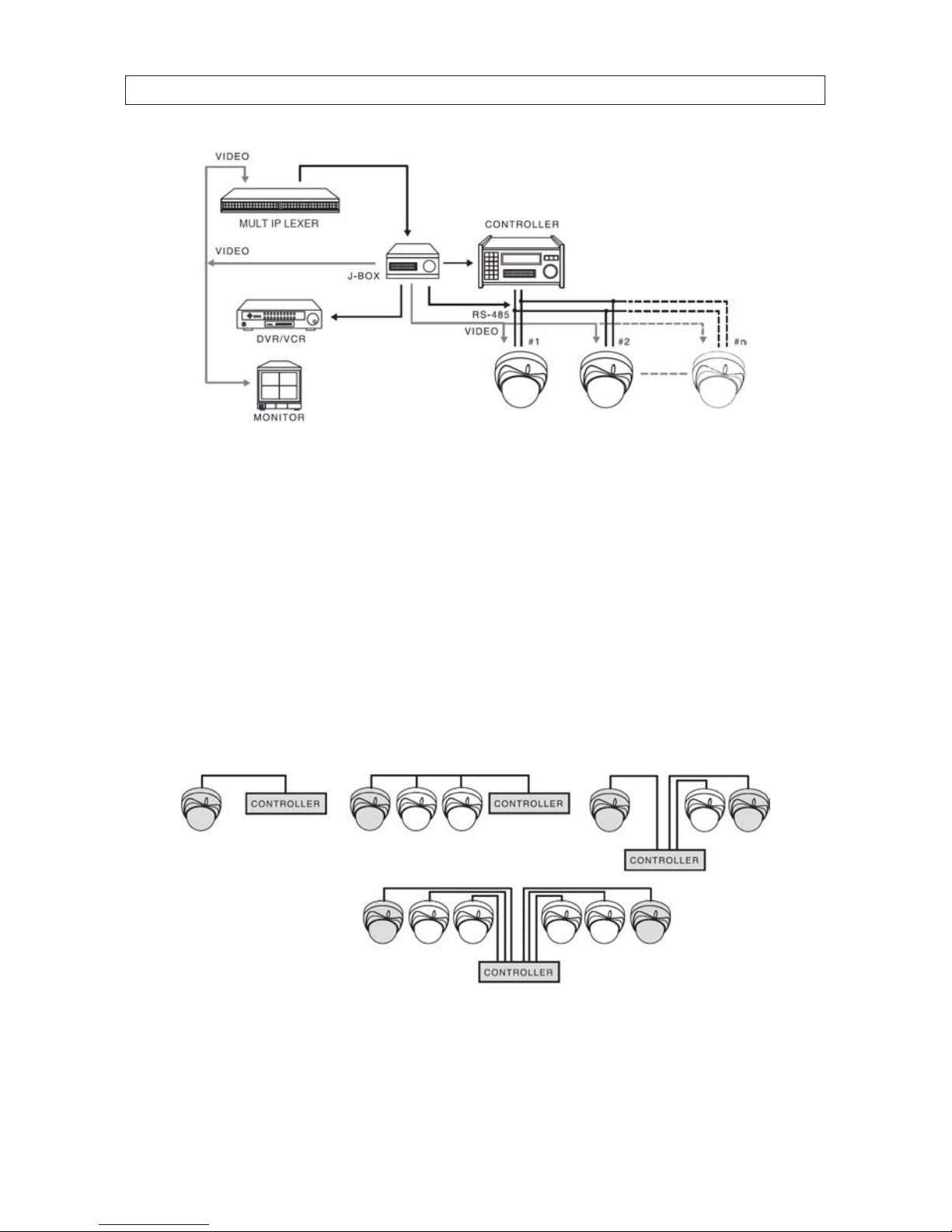
1.2 System conguration
The following illustration shows a typical PTZ camera network that includes multiple cameras, a PTZ controller, a video distribution
box (J-box), multiplexer, DVR/VCR, and a monitor.
32MP 12X PTZ HD-SDI/HDcctv Dome Camera
SECTION 1: INTRODUCTION
In the diagram above, video output from each camera on the network is applied to a distribution box (J-box), then connected to a
multiplexer, DVR/VCR, and monitor.
The PTZ features of the cameras are controlled across an RS-485 network with a PTZ controller. Up to 99 BLK-HDPTZ12 cameras can
be attached to a single RS-485 network.
1.2.1 RS-485 network termination
RS-485 networks are usually congured as a series of point-to-point (multidrop) nodes, a line or a bus (star or ring congured
networks are not recommended). Termination resisters are required for devices at the ends of the bus to reduce signal reections
in the network that can cause data corruption. The value of each termination resistor should be equal to the cable characteristic
impedance, typically 120 ohms for twisted pair cable. In the following illustration of network examples, the grayed devices are
congured to apply termination to the RS-485 bus.

4
SECTION 2: INSTALLATION
SECTION 2
Installation
2.1 General Guidelines
• The camera drop cable connects to the network cables (RS-485, alarm in/out, HD-SDI video out, 24 Vac power leads) inside
the mounting bracket provided with the camera. A cable access cover on the underside of the mounting bracket allows access
to cable connections, and to the composite video monitoring drop.
• Network cables can be routed into the mounting bracket through conduit attached to the underside of the mounting bracket,
or through the mounting bracket mounting.
• Hardware conguration switches (for camera ID, video mode, RS-485 protocol, etc.) are accessible when the camera dome
cover is removed.
• Position the camera in a location where it provides the best visibility of your surveillance targets, and is dicult to tamper with
or damage.
• Use extra care to avoid damaging the camera dome cover.
2.2 Install the mounting bracket
1. Using the mounting bracket as a template, mark the location of the mounting screw/wall anchor holes. Although bolts,
washers and wall anchors are included with the camera, these may not be appropriate for the surface where the bracket will
be attached. Always use the appropriate mounting hardware to ensure that the bracket is securely attached to the mounting
surface.
Mounting bracket
Cable access
cover
Conduit
connector
Wall anchor
Bolt and washer
52MP 12X PTZ HD-SDI/HDcctv Dome Camera
SECTION 2: INSTALLATION
2. Drill holes in the mounting surface for the wall anchors (if used) or mounting bolts.
— If the network cables will be routed into the mounting bracket where it attaches to the wall, drill an appropriate hole
for the network cables.
3. Attach the mounting bracket securely to the mounting surface using appropriate mounting hardware.
4. If conduit will be used to shield the network cables, install the conduit and attached it to the mounting bracket.
5. Remove the cable access cover from the mounting bracket.
6. Route the network cables (RS-485, alarm in/out, HD-SDI video, 24 Vac power leads) into the mounting bracket.
2.3 Set the camera hardware conguration switches
The camera hardware conguration switches are located inside the camera module. These conguration switches set the camera
device ID, video mode (NTSC or PAL), and RS-485 protocol, baud rate, and termination state.
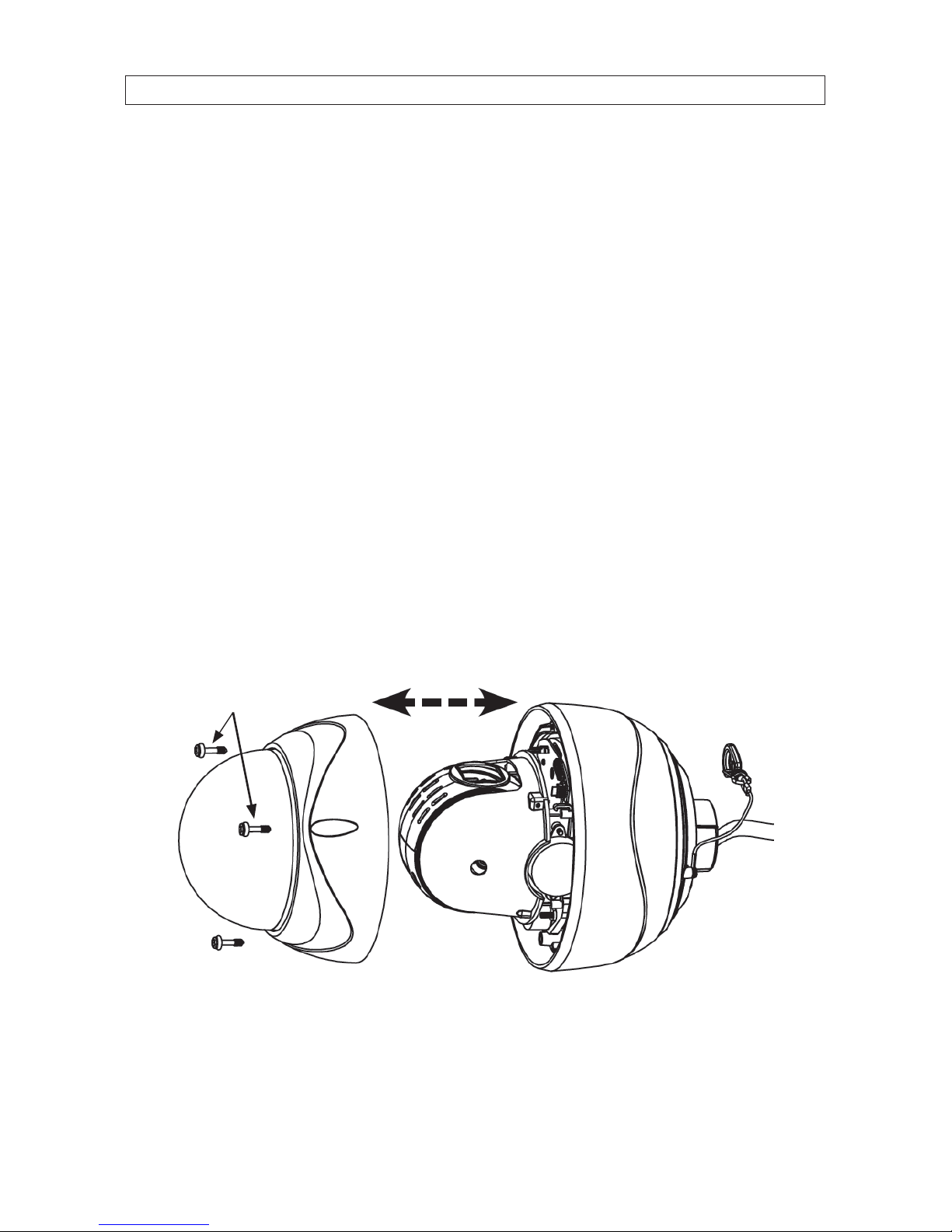
1. Remove the camera module from the packaging and place it on a at, clean surface.
2. Remove the three screws securing the dome cover and set it apart from the camera module. Note that the dome cover is
connected to the camera module with a retaining cable (not shown below).
Camera module
Safety cable
Drop
cable
Dome
cover
Dome cover screws
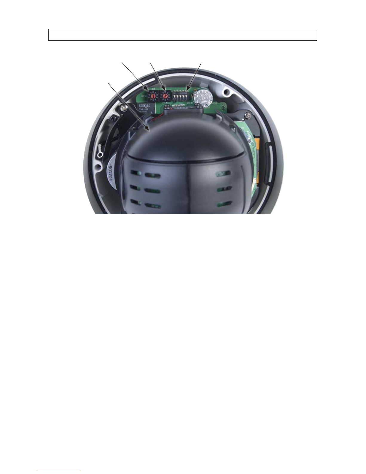
3. Set the hardware conguration switches as required for your installation. Switch functions are described below.
6
SECTION 2: INSTALLATION
SW301 SW303SW302
PTZ camera
Camera hardware switches (looking into the camera with dome removed)
SW301, SW302 switches
The SW301 and SW302 rotary switches are used to set the camera ID number in hexadecimal notation as follows:
— SW301: set to the left digit of the two-digit device ID in hexadecimal.
— SW302: Set to the right digit of the two-digit device ID in hexadecimal.
In the example above, SW301 is set to “0” and SW302 is set to “1”. Therefore, the device ID is set to “01” hexadecimal (0x01),
which equates to an ID = 1 decimal). See “Table 1. SW301, SW302 switch setting (Camera ID) reference” on page 7.

72MP 12X PTZ HD-SDI/HDcctv Dome Camera
SECTION 2: INSTALLATION
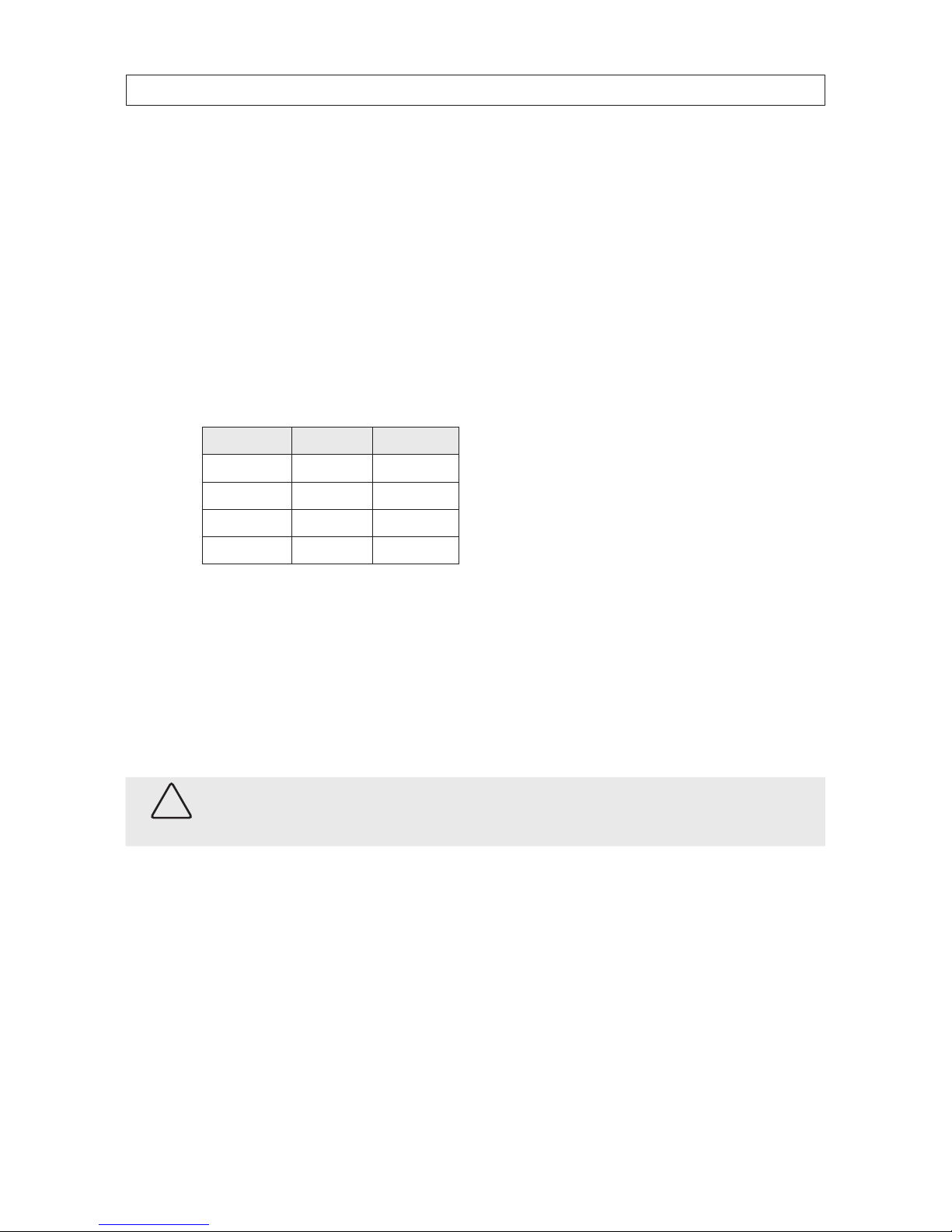
Table 1. SW301, SW302 switch setting (Camera ID) reference
8
SECTION 2: INSTALLATION
SW303 switch
The SW303 block switch contains 5 on/o switches. These switches are used as follows:
— Switch 1 (video mode):
» ON: CVBS is NTSC
» OFF: CVBS is PAL
— Switch 2 (RS-485 protocol)
» ON: Pelco P / D
» OFF: Pelco P/ Others
— Switches 3 and 4 are used together to set the RS-485 baud rate as shown in the table below.
Switch 3 Switch 4 Baud rate
O O 2400
O On 48 00
On O 9600
On On 3840 0
— Switch 5 sets the state of the RS-485 network termination:
» ON: RS-485 terminated
» OFF: RS-485 not terminated
4. Reattach the dome cover to the camera module with the three screws removed earlier.
2.4 Attach the camera module to the mounting bracket
CAUTION
When handling the camera with the dome cover attached, be extremely careful not to scratch or damage the dome cover.
1. Lift the camera module to mounting bracket, then route the camera drop cable into the bracket and out through the cable
access opening.

92MP 12X PTZ HD-SDI/HDcctv Dome Camera
SECTION 2: INSTALLATION
Lock screw
Safety cable
clip
Safety cable
clip loop
2. When inserting the top of the camera module into the mounting bracket, align the pointer on the camera module with the
safety cable clip loop as shown below, then rotate the camera module until it is fully seated.
Alignment
mark
Safety cable
clip loop
3. Tighten the lock screw.
10
SECTION 2: INSTALLATION
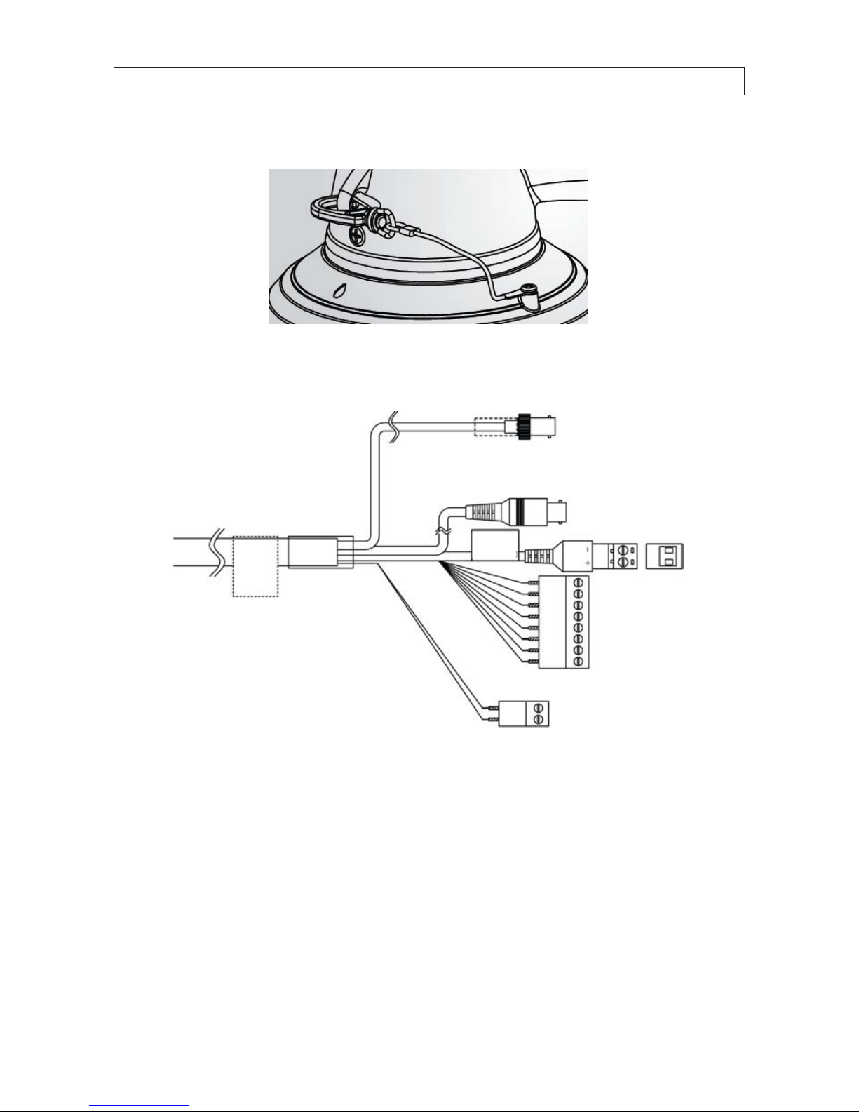
4. Clip the safety cable to the loop on the mounting bracket.
5. Connect the network RS-485, alarm in/out, and HD-SDI cables to the camera drop cable. The alarm in/out terminal block pin
denitions are shown on the label attached to the drop cable. The camera drop cable diagram is shown below.
BNC yellow connector:
Composite video (monitor)
To camera
24 Vac
power
input
BNC connector
HD-SDI video out
Terminal blocks
wire denitions
label
RS-485 TX, RX
terminal block
Alarm in/out
terminal block
6. Connect the network power leads to the 24 Vac power input terminal block.
7. Carefully pack the excess camera drop cable and network cable into the mounting bracket, then re-attach the cable access
cover.
8. Clean the camera dome with an approved glass cleaning solution and a lint free cloth.
— Dust can be removed from the unit by wiping it with a soft damp cloth. To remove stains, gently rub the surface with
a soft cloth moistened with a mild detergent solution, then rinse and dry it with a soft cloth.
— Remove all foreign particles, such as plastic or rubber materials, attached to the camera housing. These may cause
damage to the surface over time.
 Loading...