

Observint Technologies BLK-HD4E, BLK-HD4D, BLK-HD8D, BLK-HD10D, BLK-HD16D User Manual
DVR User Manual
PLEASE READ THIS MANUAL BEFORE USING YOUR RECORDER, and always follow the
instructions for safety and proper use. Save this manual for future reference.
Products: BLK-HD4E, BLK-HD4D, BLK-HD8D, BLK-HD10D, BLK-HD16D
BLK-HD4E, BLK-HDxxD_RM
© 2013 Observint Technologies, Inc.
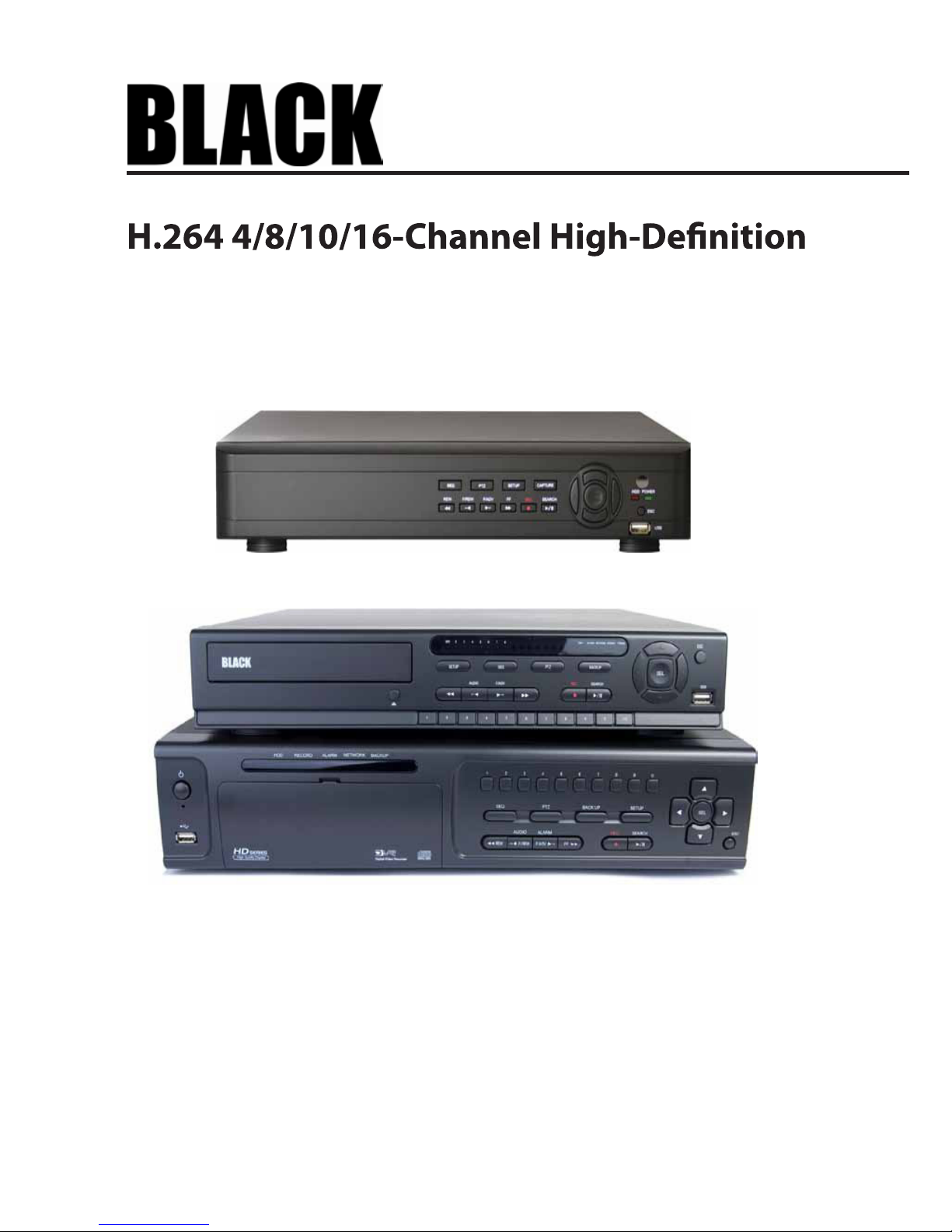
BLK-HD4D (4 channels) and BLK-HD8D (8 channels)(upper)
BLK-HD10D (10-channel hybrid) and BLK-HD16D (16 channels)
BLK-HD4E (4 channels)
ii
CAUTION
Operate this system only in environments where the temperature and humidity is within the recommended range.
Operation in temperatures or at humidity levels outside the recommended range may cause electric shock and shorten the
life of the product. Refer to the specications for each system component for more information.
LEGAL NOTICE
Observint Technologies
(Observint) products are designed to meet safety and performance standards with the use of
specic Observint authorized accessories. Observint disclaims liability associated with the use of non-Obs ervint
authorized accessories.
The recording, transmission, or broadcast of any person’s voice without their consent or a court order is strictly
prohibited by law.
Observint makes no representations concerning the legality of certain product applications such as the making,
transmission, or recording of video and/or audio signals of others without their knowledge and/or consent. We
encourage you to check and comply with all applicable local, state, and federal laws and regulations before
engaging in any form of surveillance or any transmission of radio frequencies.
Microsof t, Windows , Windows Media, and Internet Explorer are either registered trademarks or trademarks of Microsoft
Corporation in the United States and/or other countries. Android is a trademark of Google Inc. Use of this trademark
is subject to Google Permissions. Apple, iPhone, iPod touch, and iPad are registered trademarks of Apple Inc. Intel and
Pentium are trademarks of Intel Corporation in the U.S. and/or other countries.
Other trademarks and trade names may be used in this document to refer to either the entities claiming the marks
and names or their products. Obser vint disclaims any proprietary interest in trademarks and trade names other than
its own.
No part of this document may be reproduced or distributed in any form or by any means without the express written
permission of Observint, Inc.
© 2012 by Obser vint Technologies, Inc. All Rights Reserved.
11000 N. Mopac Expressway, Building 300, Austin, TX 78759
For Sales and Support, please contact your distributor.

iiiH.264 High DVR User Manual
Table of Contents
SECTION 1 Introduction
.......................................................................
1
SECTION 2 Har
dware Overview and Setup
........................................................
2
2.1 BLK-HD4E, BLK-HD4D, BLK-HD8D external features ....................................... 2
2.1.1 Front panel indicators and controls .................................................2
2.1.2 BLK-HD4E, BLK-HD4D back panel connectors .........................................4
2.1.3 BLK-HD8D back panel connectors ..................................................5
2.2 BLK-HD10D, BLK-HD16D external features ............................................... 7
2.2.1 BLK-HD10D, BLK-HD16D front panel indicators and controls ............................7
2.2.2 BLK-HD10D back panel connectors .................................................8
2.2.3 BLK-HD16D back panel connectors .................................................9
2.3 Remote Control .....................................................................11
2.4 DVD-R/W Optical drive installation ....................................................12
2.4.1 BLK-HD4D, BLK-HD8D DVD-R/W installation ........................................12
2.4.2 BLK-HD10D, BLK-HD16D DVD-R/W installation ......................................15
2.5 HDD installation ....................................................................19
2.5.1 HDD recording capacities ........................................................19
2.5.2 BLK-HD4D, BLK-HD8D HDD installation ............................................19
2.5.3 BLK-HD4D, BLK-HD8D Installing a
2nd internal HDD. . . . . . . . . . . . . . . . . . . . . . . . . . . . . . . . . .23
2.5.4 BLK-HD10D, BLK-HD16D HDD installation ..........................................24
SECTION 3 System Setup
......................................................................
28
3.1 Starting the system for the
time ...................................................28
3.1.1 Entering the SETUP menu ........................................................29
3.2 DISPLAY menu ......................................................................31
3.3 RECORD menu ......................................................................32
3.3.1 Recording Schedules ............................................................33
3.4 DEVICE menu .......................................................................35
3.5 STORAGE menu .....................................................................38
3.6 SYSTEM menu ......................................................................40
3.7 SECURITY menu. . . . . . . . . . . . . . . . . . . . . . . . . . . . . . . . . . . . . . . . . . . . . . . . . . . . . . . . . . . . . . . . . . . . .42
3.8 NETWORK menu ....................................................................44
3.8.1 Network ports .................................................................46
3.9 CONFIG menu ......................................................................47
SECTION 4 Liv
e, Search, and Playback
...........................................................
49

iv
4.1 SEARCH menu . . . . . . . . . . . . . . . . . . . . . . . . . . . . . . . . . . . . . . . . . . . . . . . . . . . . . . . . . . . . . . . . . . . . . .51
4.1.1 TIME-LINE search . . . . . . . . . . . . . . . . . . . . . . . . . . . . . . . . . . . . . . . . . . . . . . . . . . . . . . . . . . . . . . .52
4.1.2 EVENT search . . . . . . . . . . . . . . . . . . . . . . . . . . . . . . . . . . . . . . . . . . . . . . . . . . . . . . . . . . . . . . . . . .53
4.1.3 GO TO FIRST TIME search . . . . . . . . . . . . . . . . . . . . . . . . . . . . . . . . . . . . . . . . . . . . . . . . . . . . . . . . .53
4.1.4 GO TO LAST TIME search. . . . . . . . . . . . . . . . . . . . . . . . . . . . . . . . . . . . . . . . . . . . . . . . . . . . . . . . . .53
4.1.5 GO TO SPECIFIC TIME search . . . . . . . . . . . . . . . . . . . . . . . . . . . . . . . . . . . . . . . . . . . . . . . . . . . . . .53
4.2 ARCHIVE search . . . . . . . . . . . . . . . . . . . . . . . . . . . . . . . . . . . . . . . . . . . . . . . . . . . . . . . . . . . . . . . . . . . . .54
4.3 PLAY mode . . . . . . . . . . . . . . . . . . . . . . . . . . . . . . . . . . . . . . . . . . . . . . . . . . . . . . . . . . . . . . . . . . . . . . . . .55
4.4 Backup video clip . . . . . . . . . . . . . . . . . . . . . . . . . . . . . . . . . . . . . . . . . . . . . . . . . . . . . . . . . . . . . . . . . . .56
SECTION 5 PTZ Control . . . . . . . . . . . . . . . . . . . . . . . . . . . . . . . . . . . . . . . . . . . . . . . . . . . . . . . . . . . . . . . . . . . . . . . . 58
SECTION 6 Backup . . . . . . . . . . . . . . . . . . . . . . . . . . . . . . . . . . . . . . . . . . . . . . . . . . . . . . . . . . . . . . . . . . . . . . . . . . . 59
6.1 Still image BACKUP onto USB ash drive . . . . . . . . . . . . . . . . . . . . . . . . . . . . . . . . . . . . . . . . . . . . . . . .59
6.2 Video BACKUP . . . . . . . . . . . . . . . . . . . . . . . . . . . . . . . . . . . . . . . . . . . . . . . . . . . . . . . . . . . . . . . . . . . . . .59
6.3 BACKUP still images or video from the ARCHIVE list . . . . . . . . . . . . . . . . . . . . . . . . . . . . . . . . . . . . . .60
6.4 Playing backed up video clips . . . . . . . . . . . . . . . . . . . . . . . . . . . . . . . . . . . . . . . . . . . . . . . . . . . . . . . . .61
SECTION 7 Web Client . . . . . . . . . . . . . . . . . . . . . . . . . . . . . . . . . . . . . . . . . . . . . . . . . . . . . . . . . . . . . . . . . . . . . . . . 62
7.1 Connecting to the DVR with IE . . . . . . . . . . . . . . . . . . . . . . . . . . . . . . . . . . . . . . . . . . . . . . . . . . . . . . . .62
7.2 Setup
. . . . . . . . . . . . . . . . . . . . . . . . . . . . . . . . . . . . . . . . . . . . . . . . . . . . . . . . . . . . . . . . . . . . . . . . . . . . .66
7.2.1 Setup DISPLAY . . . . . . . . . . . . . . . . . . . . . . . . . . . . . . . . . . . . . . . . . . . . . . . . . . . . . . . . . . . . . . . . .66
7.2.2 Setup RECORD. . . . . . . . . . . . . . . . . . . . . . . . . . . . . . . . . . . . . . . . . . . . . . . . . . . . . . . . . . . . . . . . . .66
7.2.3 Setup DEVICE . . . . . . . . . . . . . . . . . . . . . . . . . . . . . . . . . . . . . . . . . . . . . . . . . . . . . . . . . . . . . . . . . .67
7.2.4 Setup STORAGE . . . . . . . . . . . . . . . . . . . . . . . . . . . . . . . . . . . . . . . . . . . . . . . . . . . . . . . . . . . . . . . . .68
7.2.5 Setup SYSTEM . . . . . . . . . . . . . . . . . . . . . . . . . . . . . . . . . . . . . . . . . . . . . . . . . . . . . . . . . . . . . . . . . .68
7.2.6 Setup SECURITY . . . . . . . . . . . . . . . . . . . . . . . . . . . . . . . . . . . . . . . . . . . . . . . . . . . . . . . . . . . . . . . .69
7.2.7 Setup NETWORK . . . . . . . . . . . . . . . . . . . . . . . . . . . . . . . . . . . . . . . . . . . . . . . . . . . . . . . . . . . . . . . .70
7.2.8 Setup UPGRADE . . . . . . . . . . . . . . . . . . . . . . . . . . . . . . . . . . . . . . . . . . . . . . . . . . . . . . . . . . . . . . . .70
7.2.9 Setup INFORMATION . . . . . . . . . . . . . . . . . . . . . . . . . . . . . . . . . . . . . . . . . . . . . . . . . . . . . . . . . . . .71
7.3 DVR Search. . . . . . . . . . . . . . . . . . . . . . . . . . . . . . . . . . . . . . . . . . . . . . . . . . . . . . . . . . . . . . . . . . . . . . . . .71
7.3.1 Playing recorded video . . . . . . . . . . . . . . . . . . . . . . . . . . . . . . . . . . . . . . . . . . . . . . . . . . . . . . . . . .73
7.4 Backup recorded video . . . . . . . . . . . . . . . . . . . . . . . . . . . . . . . . . . . . . . . . . . . . . . . . . . . . . . . . . . . . . . .74
7.4.1 Capture . . . . . . . . . . . . . . . . . . . . . . . . . . . . . . . . . . . . . . . . . . . . . . . . . . . . . . . . . . . . . . . . . . . . . . .75
SECTION 8 Remote Client Software . . . . . . . . . . . . . . . . . . . . . . . . . . . . . . . . . . . . . . . . . . . . . . . . . . . . . . . . . . . . . 76
8.1 PC Requirements . . . . . . . . . . . . . . . . . . . . . . . . . . . . . . . . . . . . . . . . . . . . . . . . . . . . . . . . . . . . . . . . . . . .76
8.2 Installing the Remote Client . . . . . . . . . . . . . . . . . . . . . . . . . . . . . . . . . . . . . . . . . . . . . . . . . . . . . . . . . .76
8.3 Remote Client initial display . . . . . . . . . . . . . . . . . . . . . . . . . . . . . . . . . . . . . . . . . . . . . . . . . . . . . . . . . .77
TABLE OF CONTENTS

vH.264 High Denition DVR User Manual
8.4 Setup . . . . . . . . . . . . . . . . . . . . . . . . . . . . . . . . . . . . . . . . . . . . . . . . . . . . . . . . . . . . . . . . . . . . . . . . . . . . .79
8.4.1 General Setup . . . . . . . . . . . . . . . . . . . . . . . . . . . . . . . . . . . . . . . . . . . . . . . . . . . . . . . . . . . . . . . . . .79
8.4.2 Site Setup . . . . . . . . . . . . . . . . . . . . . . . . . . . . . . . . . . . . . . . . . . . . . . . . . . . . . . . . . . . . . . . . . . . . .80
8.4.3 Event Setup . . . . . . . . . . . . . . . . . . . . . . . . . . . . . . . . . . . . . . . . . . . . . . . . . . . . . . . . . . . . . . . . . . . .81
8.4.4 Event Search Setup . . . . . . . . . . . . . . . . . . . . . . . . . . . . . . . . . . . . . . . . . . . . . . . . . . . . . . . . . . . . .82
8.4.5 Record Setup . . . . . . . . . . . . . . . . . . . . . . . . . . . . . . . . . . . . . . . . . . . . . . . . . . . . . . . . . . . . . . . . . .83
8.4.6 Record Disk Setup . . . . . . . . . . . . . . . . . . . . . . . . . . . . . . . . . . . . . . . . . . . . . . . . . . . . . . . . . . . . . .83
8.4.7 Display Setup . . . . . . . . . . . . . . . . . . . . . . . . . . . . . . . . . . . . . . . . . . . . . . . . . . . . . . . . . . . . . . . . . .84
8.4.8 About
. . . . . . . . . . . . . . . . . . . . . . . . . . . . . . . . . . . . . . . . . . . . . . . . . . . . . . . . . . . . . . . . . . . . . . . . .84
8.5 Connecting to a DVR . . . . . . . . . . . . . . . . . . . . . . . . . . . . . . . . . . . . . . . . . . . . . . . . . . . . . . . . . . . . . . . . .84
8.5.1 Bidirectional Audio . . . . . . . . . . . . . . . . . . . . . . . . . . . . . . . . . . . . . . . . . . . . . . . . . . . . . . . . . . . . .85
8.6 Remote Search mode and functions . . . . . . . . . . . . . . . . . . . . . . . . . . . . . . . . . . . . . . . . . . . . . . . . . . .85
8.6.1 Searching for and playing video recorded by the DVR . . . . . . . . . . . . . . . . . . . . . . . . . . . . . . . .87
8.6.2 Backing up video from the DVR on the Remote Client PC . . . . . . . . . . . . . . . . . . . . . . . . . . . . . .87
8.6.3 Image capture . . . . . . . . . . . . . . . . . . . . . . . . . . . . . . . . . . . . . . . . . . . . . . . . . . . . . . . . . . . . . . . . .90
SECTION 9 Multi Client Software . . . . . . . . . . . . . . . . . . . . . . . . . . . . . . . . . . . . . . . . . . . . . . . . . . . . . . . . . . . . . . 91
9.1 PC Requirements . . . . . . . . . . . . . . . . . . . . . . . . . . . . . . . . . . . . . . . . . . . . . . . . . . . . . . . . . . . . . . . . . . . .91
9.2 Installing the Multi Client . . . . . . . . . . . . . . . . . . . . . . . . . . . . . . . . . . . . . . . . . . . . . . . . . . . . . . . . . . . .91
9.3 Multi Client initial display . . . . . . . . . . . . . . . . . . . . . . . . . . . . . . . . . . . . . . . . . . . . . . . . . . . . . . . . . . . .92
9.3.1 Using Net Finder . . . . . . . . . . . . . . . . . . . . . . . . . . . . . . . . . . . . . . . . . . . . . . . . . . . . . . . . . . . . . . . .94
9.3.2 Event List . . . . . . . . . . . . . . . . . . . . . . . . . . . . . . . . . . . . . . . . . . . . . . . . . . . . . . . . . . . . . . . . . . . . . .95
9.4 Setup
. . . . . . . . . . . . . . . . . . . . . . . . . . . . . . . . . . . . . . . . . . . . . . . . . . . . . . . . . . . . . . . . . . . . . . . . . . . . .96
9.4.1 General Setup . . . . . . . . . . . . . . . . . . . . . . . . . . . . . . . . . . . . . . . . . . . . . . . . . . . . . . . . . . . . . . . . . .96
9.4.2 Event Setup . . . . . . . . . . . . . . . . . . . . . . . . . . . . . . . . . . . . . . . . . . . . . . . . . . . . . . . . . . . . . . . . . . . .96
9.4.3 Event Search Setup . . . . . . . . . . . . . . . . . . . . . . . . . . . . . . . . . . . . . . . . . . . . . . . . . . . . . . . . . . . . .97
9.4.4 Record Setup . . . . . . . . . . . . . . . . . . . . . . . . . . . . . . . . . . . . . . . . . . . . . . . . . . . . . . . . . . . . . . . . . .98
9.4.5 Record Disk Setup . . . . . . . . . . . . . . . . . . . . . . . . . . . . . . . . . . . . . . . . . . . . . . . . . . . . . . . . . . . . . .99
9.4.6 Display Setup . . . . . . . . . . . . . . . . . . . . . . . . . . . . . . . . . . . . . . . . . . . . . . . . . . . . . . . . . . . . . . . . . .99
9.4.7 Setup About . . . . . . . . . . . . . . . . . . . . . . . . . . . . . . . . . . . . . . . . . . . . . . . . . . . . . . . . . . . . . . . . . .100
9.5 Connecting to a DVR . . . . . . . . . . . . . . . . . . . . . . . . . . . . . . . . . . . . . . . . . . . . . . . . . . . . . . . . . . . . . . . .100
9.5.1 Bidirectional Audio . . . . . . . . . . . . . . . . . . . . . . . . . . . . . . . . . . . . . . . . . . . . . . . . . . . . . . . . . . . .102
9.5.2 Capture . . . . . . . . . . . . . . . . . . . . . . . . . . . . . . . . . . . . . . . . . . . . . . . . . . . . . . . . . . . . . . . . . . . . . .102
9.5.3 Record
. . . . . . . . . . . . . . . . . . . . . . . . . . . . . . . . . . . . . . . . . . . . . . . . . . . . . . . . . . . . . . . . . . . . . . .103
9.6 Remote playback and backup . . . . . . . . . . . . . . . . . . . . . . . . . . . . . . . . . . . . . . . . . . . . . . . . . . . . . . . .103
9.6.1 Remote playback . . . . . . . . . . . . . . . . . . . . . . . . . . . . . . . . . . . . . . . . . . . . . . . . . . . . . . . . . . . . . .103
TABLE OF CONTENTS

vi
9.6.2 Backing up video from the DVR on the Multi Client PC . . . . . . . . . . . . . . . . . . . . . . . . . . . . . . .106
9.7 Local playback . . . . . . . . . . . . . . . . . . . . . . . . . . . . . . . . . . . . . . . . . . . . . . . . . . . . . . . . . . . . . . . . . . . . .107
9.7.1 AVI backup during playback . . . . . . . . . . . . . . . . . . . . . . . . . . . . . . . . . . . . . . . . . . . . . . . . . . . .109
SECTION 10 Specications . . . . . . . . . . . . . . . . . . . . . . . . . . . . . . . . . . . . . . . . . . . . . . . . . . . . . . . . . . . . . . . . . . . . 111
APPENDIX A DVR Compatible Hard Disk Drives . . . . . . . . . . . . . . . . . . . . . . . . . . . . . . . . . . . . . . . . . . . . . . . . . . . . 113
APPENDIX B Device Log . . . . . . . . . . . . . . . . . . . . . . . . . . . . . . . . . . . . . . . . . . . . . . . . . . . . . . . . . . . . . . . . . . . . . . . 115
APPENDIX C DVR Setup Menu Components . . . . . . . . . . . . . . . . . . . . . . . . . . . . . . . . . . . . . . . . . . . . . . . . . . . . . . 116
TABLE OF CONTENTS

1H.264 High Denition DVR User Manual
SECTION 1: INTRODUCTION
SECTION 1
Introduction
Features
• H.264 Video compression
• HDcctv/HD-SDI compatible
• HDMI 1080p video output
• Bi-directional audio over network via Network Client Software, Web-Viewer, CMS, and Mobile Viewer
• Individual channel operation
• Motion detection
• Graphic user interface
• Software upgradable via USB ash drive or network software.
• Backup via USB ash drive, network or DVD-RW
• Exclusive le format and AVI backup
• Time stamp over AVI backup data for court evidence
• S.M.A.R.T. (Self-Monitoring, Analysis, and Reporting Technology for HDD)
• Automatic video input and video loss detection
• Covert camera operation (provides enhanced security)
• Built-in PTZ camera control
• Network access via network client software, web viewer, CMS, and mobile viewer
Your DVR includes:
• DVR (DVD-R/W drive and hard disk drive (HDD) optional)
• Mounting screws, grommets, SATA data cables for HDDs (if HDDs are not installed)
• Mounting screws and SATA data cable for DVD-R/W (if DVD-R/W is not installed)
• Software CD containing the Single (Remote) Client, Multi Client, and the DVR user manual (this document)
• Remote control
• Battery 1.5V (2 x AAA)
• Power cables (12 Vdc, 5 A adapter for BLK-HD4D, BLK-HD8D only)
• Rack mount brackets (BLK-HD10D, BLK-HD16D only)
• Mouse
• Quick start guide document
2
SECTION 2: HARDWARE OVERVIEW AND SETUP
SECTION 2
Hardware Overview and Setup
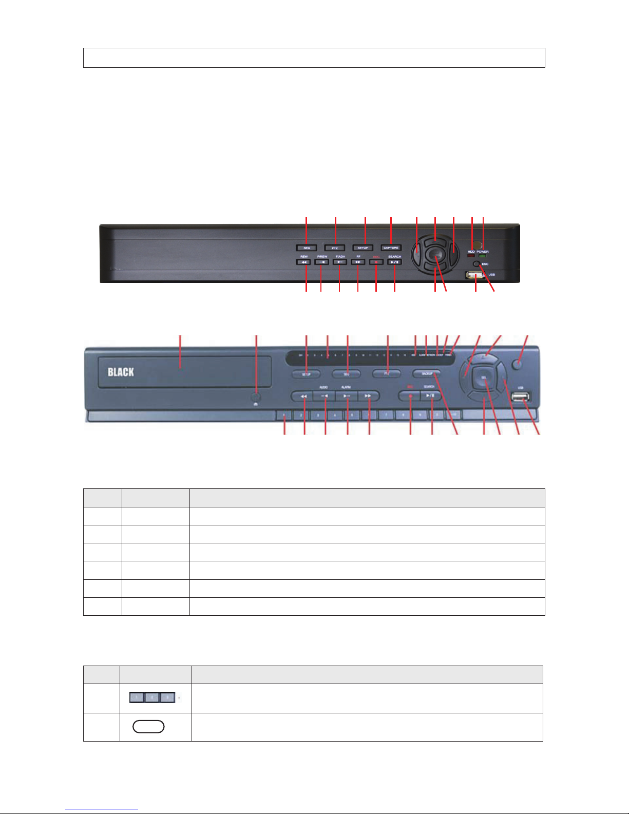
2.1 BLK-HD4E, BLKHD4D, BLK-HD8D external features
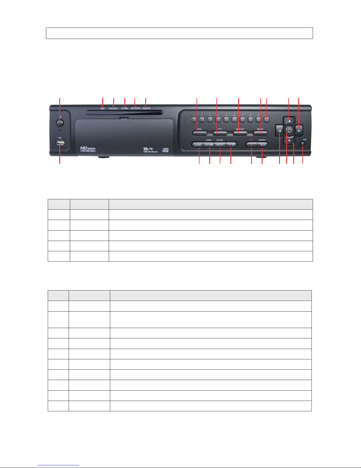
2.1.1 Front panel indicators and controls
1
13
19
16A F
2 148
2223 20D
5 17
11 B
3, 4
15
9, 10 21
E
6, 7 18
12 C
Table 1. Front Panel LED Indicators
No. Name Description
A CH1~4, 8 Indicates that the channel is being recorded.
B HDD Indicate s that the system is acce ssing the hard disk.
C ALARM Indicates when a senso r is triggered or motion is detecte d.
D NETWORK Indicates that a network client is conne cted.
E BACKUP Indicates that a USB or DVD-R/W s torage device is s toring images or video.
F POWER Indicate s that the system is switched on.
Table 2. Front panel buttons
No. Name Description
1
Channel keys. For c hannel 10, press the 0 key. For channel 11, press the +10 and 1 key. For channel 16, press the +10
and 6 key.
2
Press to rewind the video in playbac k mode.
2 3,4 5,6 7 8 9,10
1112 13 14 15 16 17
1819 2021
B F
BLK-HD4E (4 channels)
BLK-HD4D, BLK-HD8D
3H.264 High DVR User Manual
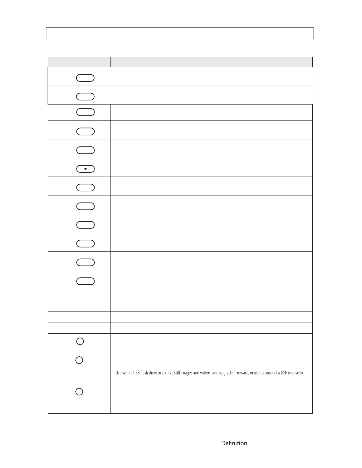
No. Name Description
5
Press to fast forward the footage in p layback mode.
6
..
ALARM
Press to enable/disab le ALARM operation.
7
..
ALARM
Jump/Step forward. In playbac k mode, the playback position moves 60 s econds forward.
8
REC
Press to start o r stop manual recording.
9
/ ll
SEARCH
Press to op en the SEARCH menu in live display mode.
10
/ ll
SEARCH
Press to play/pause the r ecording in playb ack mode.
11
SETUP
Press to enter SETUP menu.
12
SEQ
Enable/disable th e automatic sequence display of channels in full screen, qua d-split, and 9-split display mode.
13
PTZ
Press to control Pan/Tilt/Zo om operations.
14
BACKUP
Press to capture live or playback mod e video in JPEG fo rmat.
15
(LEFT)
Press to move lef t or to change the valu es in Setup mode. When enter ing a password, it inserts a 4.
16
(UP)
Press to move up the menu in Setup mode. When entering a password, i t inserts a 1.
17
(RIGHT)
Press to move right or to change the values in Setup mode. When entering a password, i t inserts a 2.
18
(DOWN)
Press to move down th e menu in Setup mode. When entering a password, it ins erts a 3.
19
SEL
Press to select desired menu item or to store the setup value.
20
ESC
Press for tempor ary storage of the changed value or to return to the previous menu s creen.
21 USB Port
the DVR.
22
To open and close the inser t tray, press the button
23 DVD Drive To save vide o, insert a CD-R/DVD-R
SECTION 2: HARDWARE OVERVIEW AND SETUP
3
..
AUDIO
Press to select audio mode such as SINGLE (highlighted channel), MIX (combine all channels), or MUTE (all channels).
4
..
AUDIO
Jump/step backward. In playback mo de, the playback p osition moves 60 seconds back ward.
4
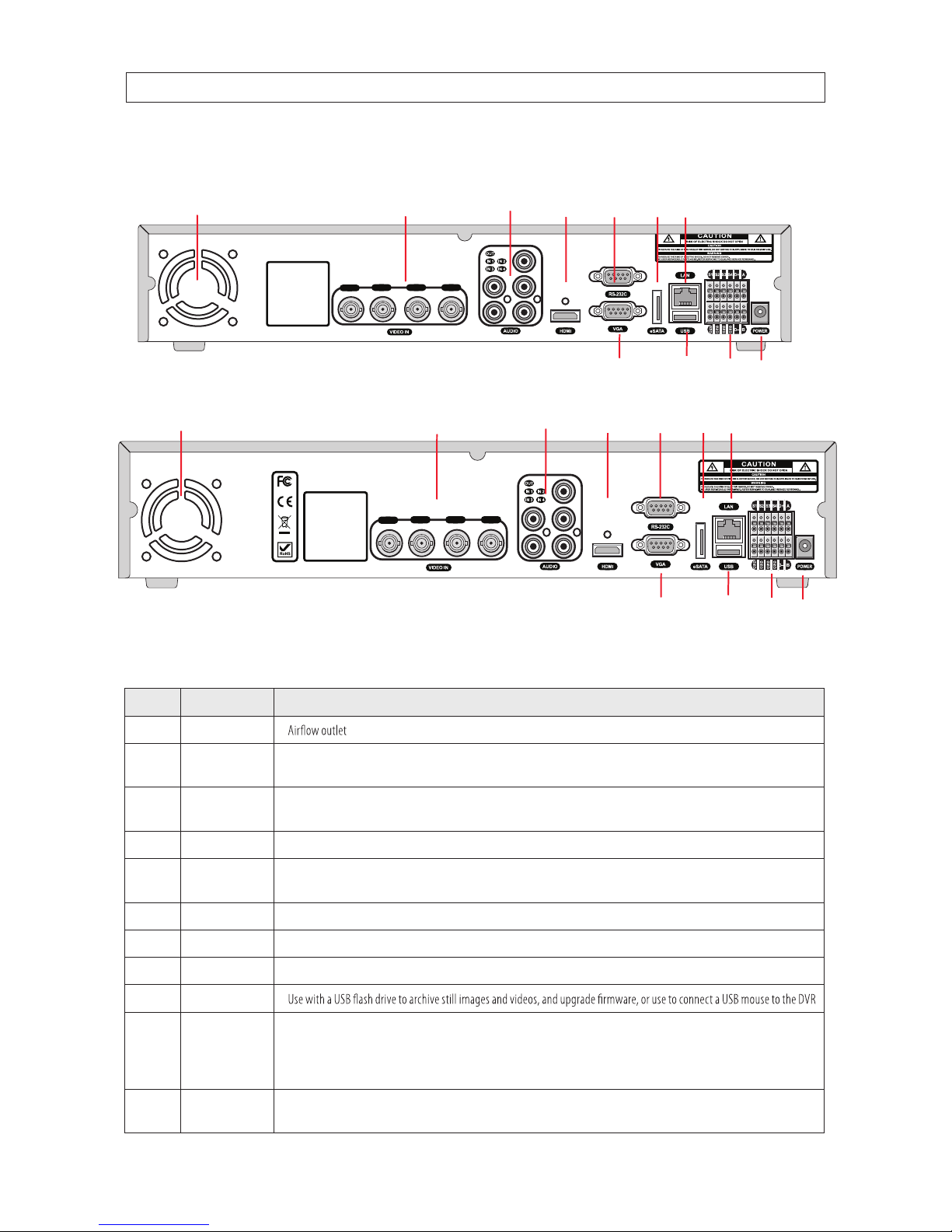
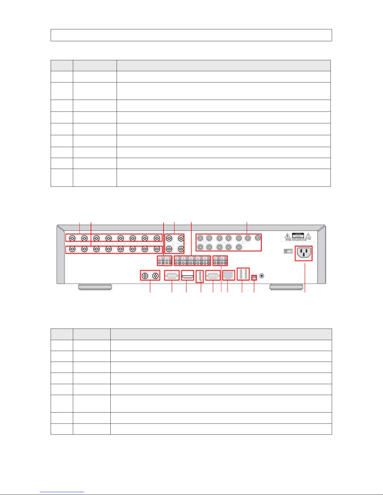
2.1.2 BLK-HD4E, BLK-HD4D back panel connectors
7108
119
1 42 53
6
BLK-HD4E back panel
Table 3. BLK-HD4E, BLK-HD4D back panel connectors
No. Name Description
1 Fan
2
HDCCTV / 1.0
INPUTS
HD-SDI video inputs
3
AUDIO IN
AUDIO OUT
4 RCA connectors fo r audio input
1 RCA connector for audio out put
4 HDMI HDMI video out.
5
RS-232
interface
Used for test ing only.
6 VGA Connec tor for a VGA monitor.
7
eSATA port
Connec tor for external s torage
8
ETHERNET
RJ- 45 connector for LAN connec tion.
9 USB
10
RS-485,
sensor and
alarm
terminations
RS-485 PTZ camera control terminals. See descr iption below.
11
POWER
SOCKET
Connec t DC12V 5A power adaptor
SECTION 2: HARDWARE OVERVIEW AND SETUP
CH 1
CH 2 CH 3 CH 4
CH 1
CH 2 CH 3 CH 4
7 8
1
42 53
10 1196
BLK-HD4D back panel
5H.264 High Denition DVR User Manual
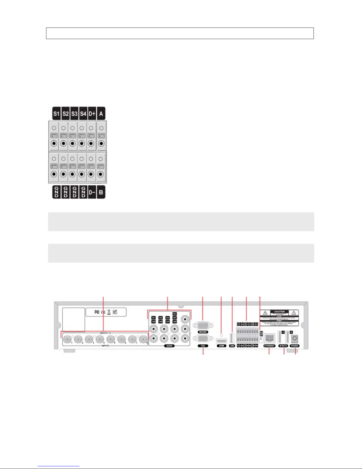
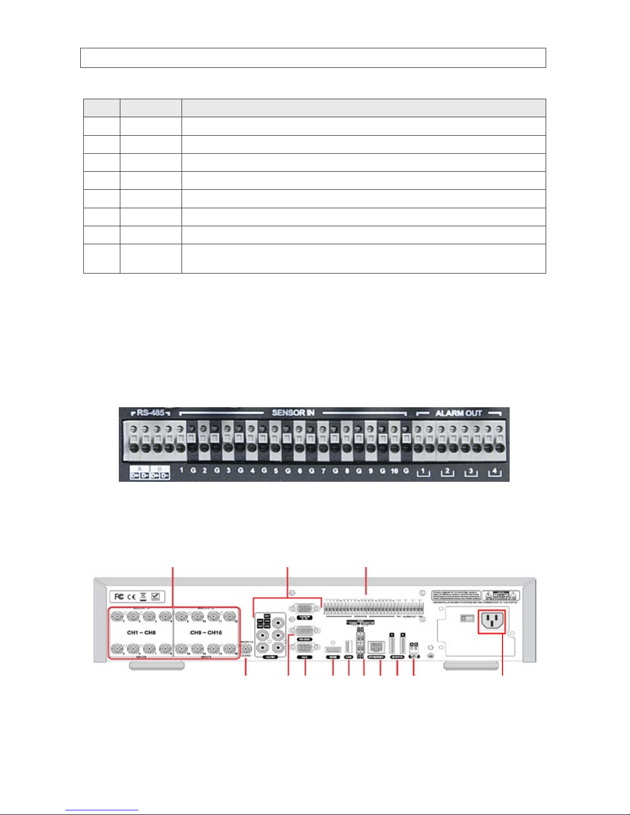
BLK-HD4D RS485 sensor and alarm termination block
Use the back panel termination block to connect sensor, RS-485, and alarm out cables.
Termination block pin denitions:
S1, GND: Sensor 1 input
S2, GND: Sensor 2 input
S3, GND: Sensor 3 input
S4, GND: Sensor 4 input
D+, D-: RS-485A and RS-485Bt
A, B: Alarm output
NOTE
S1 - S4 sensor inputs can be normally open (N.O.) or normally closed (N.C.). To congure the sensor t ype, go to
SETUP -> Device -> Sensor: Type.
NOTE
A - B (alarm out) can be triggered by any single of combination of sensors and motion on or video loss in up to four camera
channels. To congure alarm causing conditions, go to: SETUP -> Device -> Alarm Out.
2.1.3 BLK-HD8D back panel connectors
7108
119
1
4
2 53 6
BLK-HD8D back panel
SECTION 2: HARDWARE OVERVIEW AND SETUP
6
Table 4. BLK-HD8D back panel connectors
No. Name Description
1
HDCCT V 1.0
1 - 8 Input s
HD-SDI inp ut
2
AUDIO IN
AUDIO OUT
8 RCA connectors for audio input
1 RCA connector for au dio output
3
RS-232
inter face
Used for test ing only.
4 VGA Connec tor for a VGA monitor.
5 HDMI HDMI video out.
6 USB Use with a USB ash drive to archive s till images and v ideos, and upgrade r mware, or use to connect a USB mouse to the DVR
7
Sensor / alarm
terminations
See description below.
8 RS-4 85 R S-485 PTZ c amera control terminals
9 ETHERNET RJ-45 connector for LAN co nnection.
10 eSATA port Connector for e xternal storage
11
POWER
SOCKET
Connec t DC12V 5A power adaptor
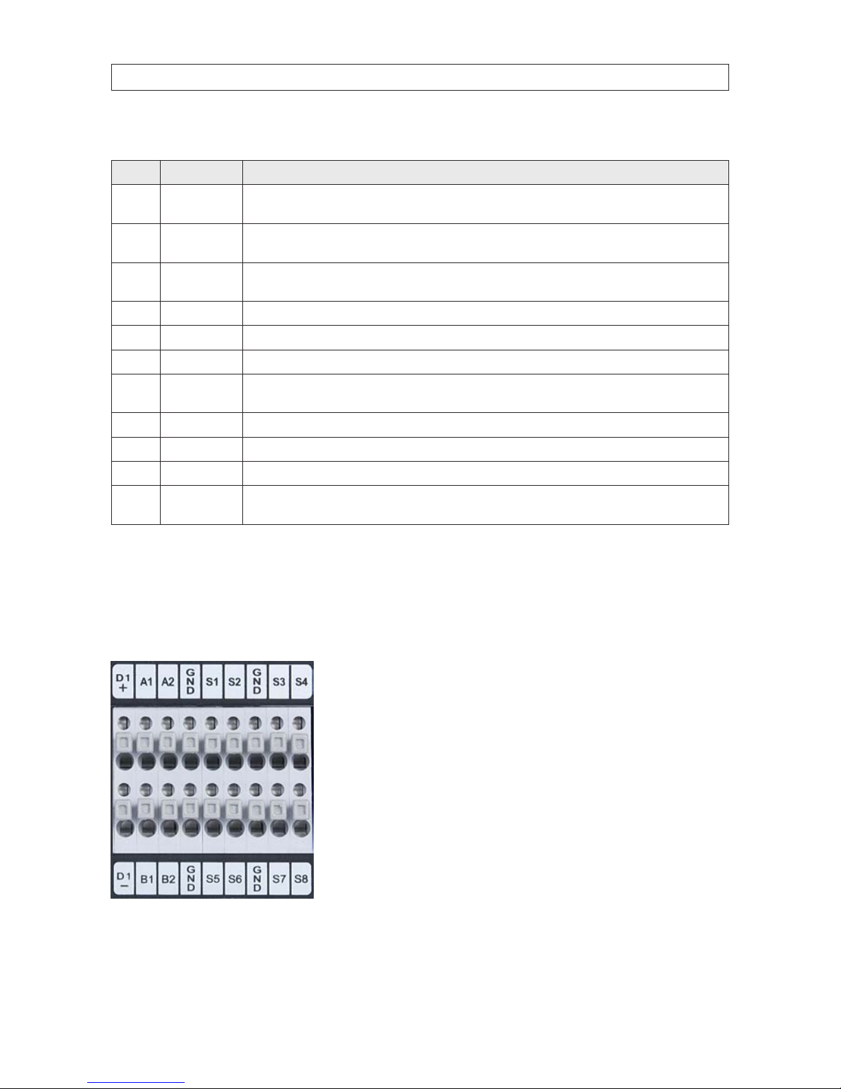
BLK-HD8D sensor and alarm termination block
Use the back panel termination block to connect sensor (8), RS-485 (1), and alarm out (2) cables.
Termination block pin denitions:
S1, GND: Sensor 1 input
S2, GND: Sensor 2 input
S3, GND: Sensor 3 input
S4, GND: Sensor 4 input
D+, D-: RS-485A and RS-485Bt
A1 + B1, A2 + B2: Alarm outputs
SECTION 2: HARDWARE OVERVIEW AND SETUP
7H.264 High Denition DVR User Manual
2.2 BLK-HD10D, BLK-HD16D external features
2.2.1 BLK-HD10D, BLK-HD16D front panel indicators and controls
719 16108 1711 159 1812
1 134A 2 14D 5B 3E 6C
Table 5. Front panel LED indicators
No. Name Descriptio n
A HDD Indicates that the system is accessing the hard disk.
B RECORD Indicate s that the sys tem is recording video.
C AL ARM Indicates when a sensor is triggered or motion is detecte d.
D NETWORK Indicates that a network client is connected.
E BACKUP Indicates that a USB or DV D-R/W storage d evice is storing image s or video.
Table 6. Front panel buttons
No. Name Description
1 POWER Power ON/OFF
2 NUMBER
Channel selec t keys. For channel “10”, press the “0” key. For channel “11”, press the “+10” key and the “1” key. For channel “16”, press the “+10” key and the “6” key.
3 SEQ Enable/disable the automatic display of channels in full screen, quad, and 9 -split screen mode.
4 PTZ Pre ss to control pan/tilt /zoom operat ions.
5 SETUP Press to open the SE TUP menu.
6 BACKUP Press to capture video in jpeg format du ring display dur ing live or playback mode.
7 REW Press to rewind in playback mode.
8 F/REV Jump/step backwards. In playbac k mode, the jump moves 60 seconds back.
9 F/ADV Jump/step forwards. In play back mode, the jump move s 60 seconds forward.
10 FF Press to fast f orward in play back mode.
SECTION 2: HARDWARE OVERVIEW AND SETUP
8
No. Name Description
11 REC Press to star t or stop manual recording.
12
SEARCH
PLAY/PAUSE
During LIVE display mode, press to open the SEARCH menu.
During PLAYBACK mode, press to play or pause.
13
p (UP)
Press to move up the menu in SE TUP mode. When entering a password, it inser ts a 1.
14
u (RIGHT )
Press to move right or to change the values in SETUP mode. When entering a password, i t inserts a 2.
15
q (DOWN)
Press to move down the menu in Setup mode. When enter ing a password, it inserts a 3.
16
t (LEFT)
Press to move lef t or to change the values in Setup mode. When entering a pa ssword, it insert s a 4.
17 SEL Press to selec t the highlighted menu item or store the s etup value.
18 ESC Press for temporary s torage of the changed value or to return to the previous menu screen.
19 USB Port
Use with a USB ash dr ive to archive st ill images and videos an d upgrade rmw are, or use to conne ct a USB mouse to
the DVR.
2.2.2 BLK-HD10D back panel connectors
1
137
4
1610
2
148
5
11
3
159
6
12
Table 7. BLK-HD10D back panel connectors
No. Name Description
1 VIDEO IN 8 BNC connectors fo r composite vid eo input (NTSC /PAL) Channels 1 - 8.
2 LOOP 8 BNC conne ctors for video ou tput (loop back).
3 RS-4 85 1st and 2nd po rts for RS -485 network (camera and controller)
4 SPOT 4 composite video ou tputs for sp ot monitoring.
5 SENSOR IN 8 terminations f or sensor device conne ction
6
AUDIO IN
AUDIO OUT
8 connec tors for audio input (channels 1 - 10)
1 connec tor for audio output
7 VIDEO IN 2 HD-SDI connec tors for vide o input (channels 9. 10).
8 VGA Connec tor for a VGA monitor.
SECTION 2: HARDWARE OVERVIEW AND SETUP
9H.264 High Denition DVR User Manual
No. Name Description
9 HDMI OUT Main video out (1280 x 720p)
10 USB Use wi th a mouse or for backup.
11 RS-232 Not use d at this time.
12 ALARM OUT 2 terminations for alarm device connection. Provides simple on/o switching wit h a relay (0.5 A / 125 Vac, 1 A / 30 Vac)
13 ETHERNET RJ-45 connec tor for LAN connec tion.
14 eSATA port 2 eSATA por ts for archive of still images or video to an ex ternal HDD. Conne ctor for ex ternal stor age
15 RS-4 85 R S-485 A and B ne twork termination switches ON/OFF
16
POWER
SOCKET
Connec t 110 ~ 2 50 Vac power.
RS-485, Sensor in, Alarm out terminations
Two RS-485 networks can be attached to the backpanel. Network termination can be applied independently to each input. See
item 15 in “BLK-HD4D RS485 sensor and alarm termination block” on page 5 above.
10 sensor input and 4 alarm output terminations are provide on the backpanel. Sensors can be normally open (NO) or normally
closed (NC). Alarms provide using simple On/O switching through a relay; output is rated at: 0.5 A /125 Vac, 1 A / 30 Vac.
BLK-HD10D RS-485, sensor input and alarm output terminations
2.2.3 BLK-HD16D back panel connectors
1
1374 10
2
85 11
3
96 12
SECTION 2: HARDWARE OVERVIEW AND SETUP
10
SECTION 2: HARDWARE OVERVIEW AND SETUP
Table 8. BLK-HD16D back panel connectors
No. Name Description
1 VIDEO IN HDCCTV 1.0 video input. Channels 1 - 8, 9 - 16.
2
AUDIO IN
AUDIO OUT
Audio input. Channels 1 - 4, 5 - 16
1 channel audio ou t.
3 SENSOR IN S ensor in terminations.
4 VIDEO OUT HDCCTV 1.0 video output.
5 RS-232C For tes ting only.
6 VGA Connec tor for a VGA monitor.
7 HDMI HDMI video out.
8 USB
9 RS-4 85 R S-485 termination for PT Z camera control.
10 ETHERNET RJ-45 connec tor for LAN connec tion.
11 eSATA port Connector for e xternal storage
12 RS-4 85 R S-485 A and B ne twork termination switches ON/OFF
13
POWER
SOCKET
Connec t 110 ~ 2 50 Vac power.
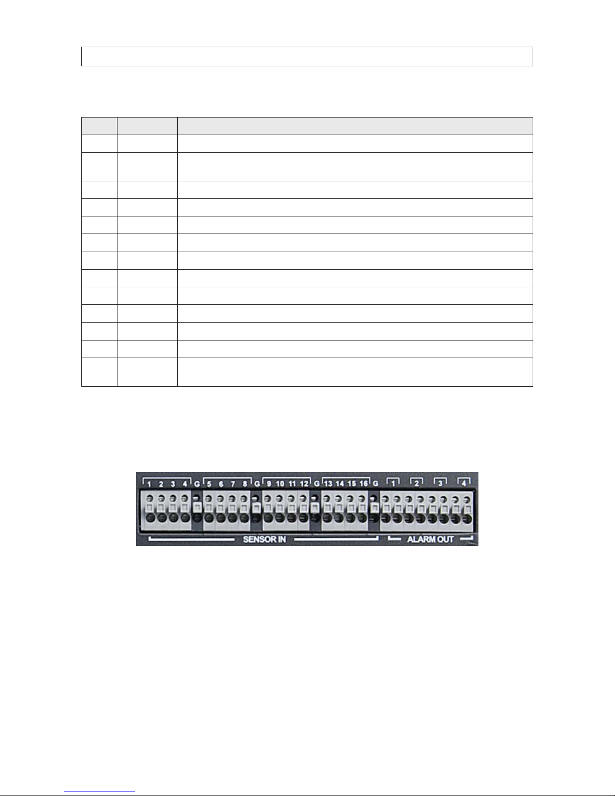
Sensor in, Alarm out terminations
16 sensor input and 4 alarm output terminations are provided on the backpanel. Sensors can be normally open (NO) or normally
closed (NC). Alarms provide using simple On/O switching through a relay; output is rated at: 0.5 A /125 Vac, 1 A / 30 Vac.
BLK-HD16D sensor input and alarm output terminations
11H.264 High Denition DVR User Manual
SECTION 2: HARDWARE OVERVIEW AND SETUP
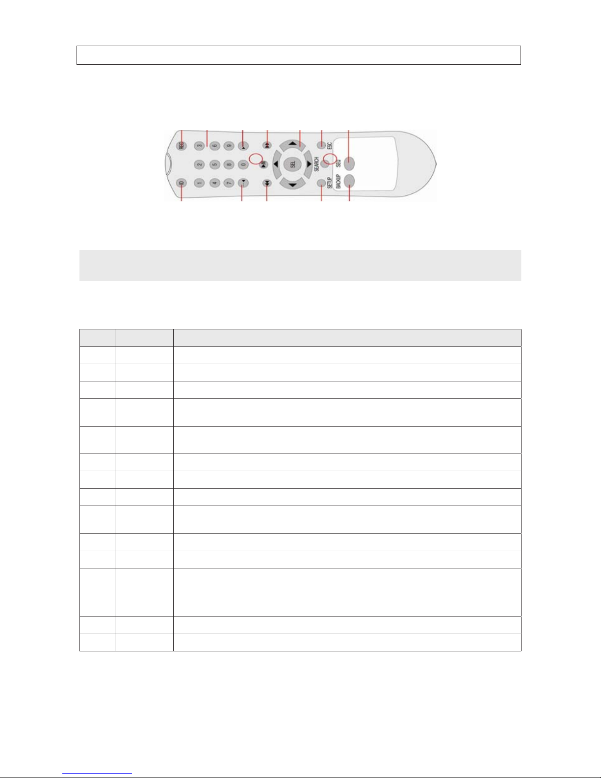
2.3 Remote Control
1 13
7
4 10
2 1485
11
3 9612
Typical Remote Control
NOTE
The remote control provided with your DVR may appear dierent from the one shown above. However, the buttons function as
described in the table below.
Table 9. Remote Control Button Functions
No. Name Function
1 ID When a remote control ID number is se tup in DVR, press this button b efore the numb er.
2 REC To start and stop manual re cording.
3 0 .. 9 To select channel (1, 2, 3, ..) or to enter a DVR ID number.
4 F/REW
During Playback – To move the playback posit ion 60 seconds back.
During Pause – To move t he playback position 1 frame back.
5 F/ADV
During Playback – To move the playback posit ion 60 seconds forward.
During Pause – To move t he playback position moves 1 f rame forward.
6 REW To rewind the recording. Press again to increase the rewind speed.
7 PLAY/PAUSE To play or to pause the recording in playback mode.
8 FF To fast for ward the recording. Press again to increase th e fast forward spe ed.
9
Direction
Buttons
Press to move to menu items or selec t a channel.
10 SETUP To open t he SETUP menu.
11 SEARCH To go to the SE ARCH menu.
12 ESC
During setup – To return to the previous menu scre en.
During playback – To exit playback mode
System lock – To lock a s ystem when pressing ESC but ton for 5 seconds.
System unlock – To unlock a system wh en pressing ESC button for 5 s econds.
13 BACKUP To start a backup operations in live or playb ack mode.
14 SEQ To start auto sequencing the screen in full screen mod e. (Toggle)
12
SECTION 2: HARDWARE OVERVIEW AND SETUP
2.4 DVD-R/W Optical drive installation
2.4.1 BLK-HD4D, BLK-HD8D DVD-R/W installation
If your DVR does not include an internal DVD-R/W drive, use the following procedure to install one. The DVD-R/W can be used to
archive stored data including video clips and snapshots. Your DVR will accommodate one standard-size desktop system DVD-R/W
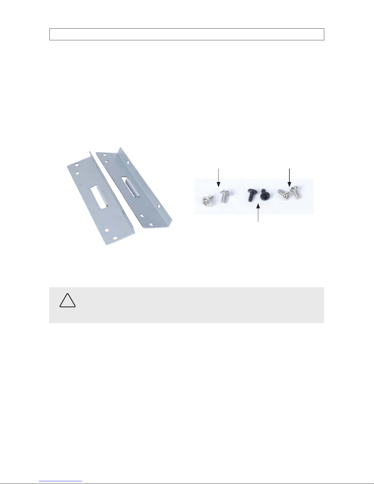
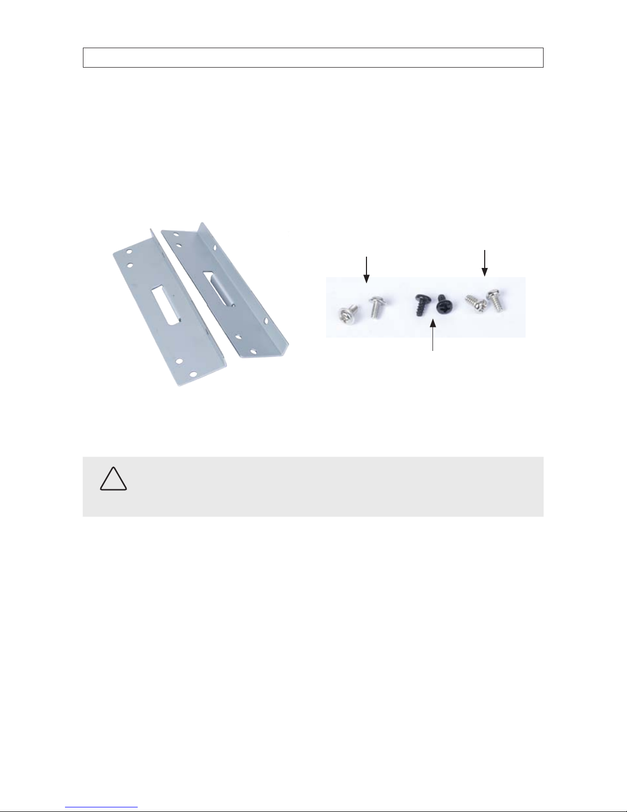
drive with a serial-ATA (SATA) interface. If your DVR was purchased without a DVD-R/W drive or HDD drive, a hardware kit,
including mounting brackets, screws and cables is included with the DVR.
For attaching bracket
to DVD-R/W (at-head,
ne-thread screws (4))
For attaching bracket to
HDD (pan-head, medium-
thread screws (4))
For attaching bracket
to chassis (pan-head,
course-thread screws)
Mounting brackets (one pair per drive) Screw types
To install a DVD-RW drive, carefully follow the procedure below.
CAUTION
Follow recommended electrostatic discharge (ESD) guidelines while performing this procedure. Install the DVD-R/W drive in
a static-free environment, wearing a certied ESD wrist strap. If a static free environment and ESD wrist strap is not available,
touch the bare metal of the DVR chassis frequently when installing the drive to dissipate the static charge naturally generated
on your skin and clothing.
1. If your DVR is powered on, use the menu system to perform a System Shutdown.
a. Right click anywhere on the live view screen, then click SYSTEM SHUTDOWN in the pop-up menu (see “3.1 Starting
the system for the rst time” on page 28), or click the SYSTEM SHUTDOWN icon on the taskbar.
b. Follow the on-screen instructions for shutting down the system.
2. Disconnect the power adapter from the back of the DVR.
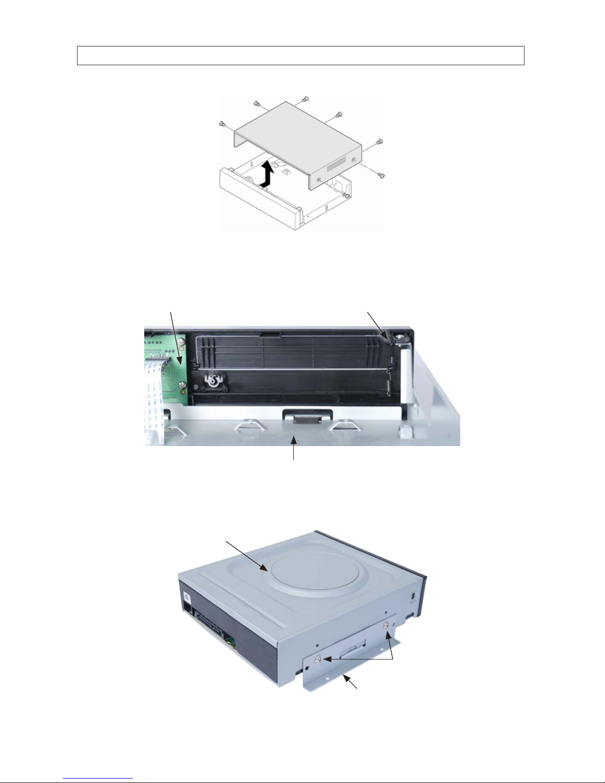
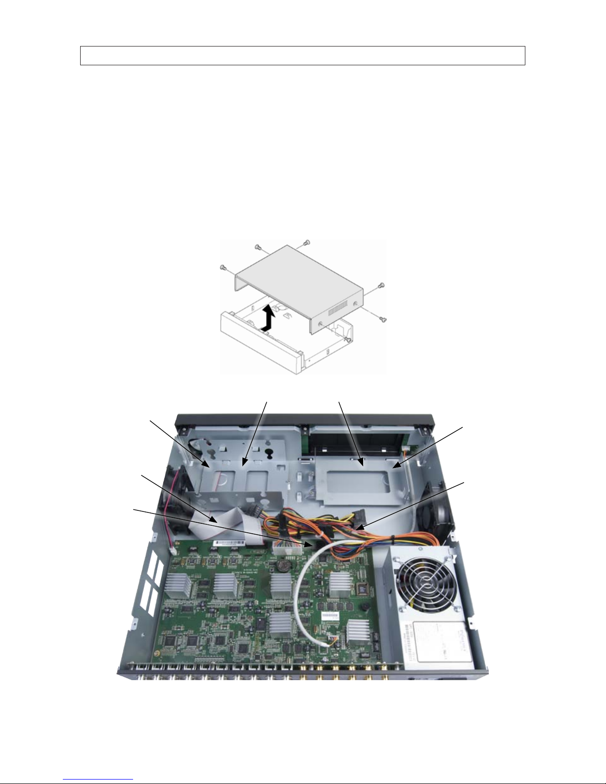
3. Remove the top cover from the DVR by removing the three cover screws on the back of the chassis, and the two on each side.
See the drawing below.
13H.264 High Denition DVR User Manual
SECTION 2: HARDWARE OVERVIEW AND SETUP
13
4. Remove the optical drive tray door retaining screw from the inside of the DVR front panel. See the picture below. Use a #1
Phillips screwdriver.
Optical drive tray door
retaining screw location
Back side of
DVR front panel
Optical drive bay
5. Attach a mounting bracket to each side of the DVD-R/W drive as shown below using the at-head ne thread screws
provided. Use two screws for each bracket. Tighten the screws until snug.
DVD-R/W drive
Mounting bracket
Flat-head ne-thread
screws (2)
14
SECTION 2: HARDWARE OVERVIEW AND SETUP
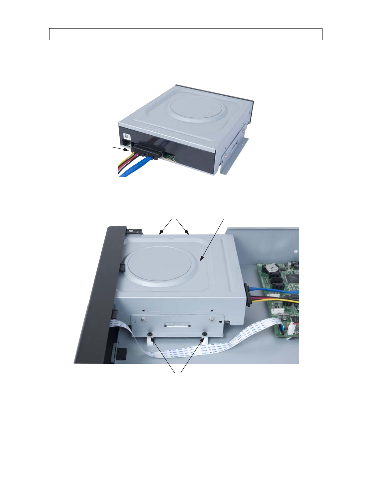
6. Plug a SATA data and power cable assembly into the mating connectors on the back of the DVD-R/W drive. Ensure the
connector is fully seated.
SATA data and
power cable
7. Position the DVD-R/W drive in the optical drive bay as shown below. Secure the drive to the chassis with four screws through
the mounting brackets, two on each side. Use black pan-head course-thread screws provided. Tighten the screws until snug.
DVD-R/W drive in optical drive bayScrews
Screws
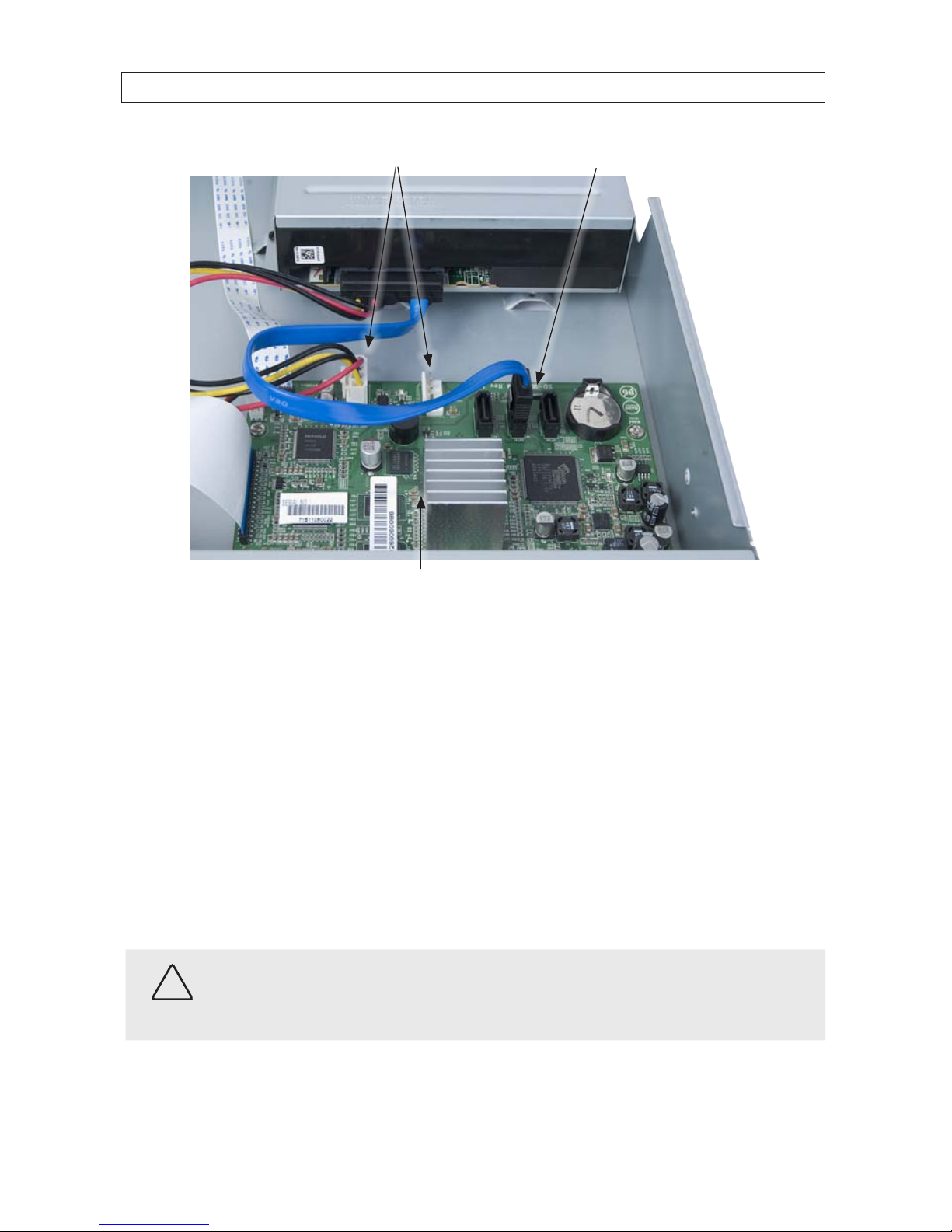
8. Plug the SATA data cable (blue cable) into the SATA1 connector on the PC board, then plug the SATA power cable into one of
the SATA power connectors on the PC board.
15H.264 High Denition DVR User Manual
SECTION 2: HARDWARE OVERVIEW AND SETUP
SATA1 connector
SATA power connectors
PC board
Ensure that the data and power cable connectors are fully seated onto the connectors on the PC board.
9. Reinstall the DVR cover using the 7 screws removed earlier.
10. Reattach the power adapter to the back of the DVR.
2.4.2 BLK-HD10D, BLK-HD16D DVD-R/W installation
If your DVR does not include an internal DVD-R/W drive, use the following procedure to install one. The DVD-R/W can be used to
archive stored data including video clips and snapshots. Your DVR will accommodate one standard-size desktop system DVD-R/W
drive with a serial-ATA (SATA) interface. If your DVR was purchased without a DVD-R/W drive or HDD drive, a hardware kit,
including screws and cables, and a mounting bracket is included with the DVR. To install a DVD-RW drive, carefully follow the
procedure below.
CAUTION
Follow recommended electrostatic discharge (ESD) guidelines while performing this procedure. Install the DVD-R/W drive in
a static-free environment, wearing a certied ESD wrist strap. If a static free environment and ESD wrist strap is not available,
touch the bare metal of the DVR chassis frequently when installing the drive to dissipate the static charge naturally generated
on your skin and clothing.
1. If your DVR is powered on, use the menu system to perform a System Shutdown.
16
SECTION 2: HARDWARE OVERVIEW AND SETUP
a. Right click anywhere on the live view screen, then click SYSTEM SHUTDOWN in the pop-up menu (see “3.1 Starting
the system for the rst time” on page 28), or click the SYSTEM SHUTDOWN icon on the taskbar.
b. Follow the on-screen instructions for shutting down the system.
2. Disconnect the power cord from the back of the DVR.
3. Remove the top cover from the DVR by removing the two cover screws on the back of the chassis, and the two on each side.
See the drawing below.
DVD drive
mounting
bracket
HDD drives
mounting
bracket
HDD drives bay
SATA
connectors
Front panel
ribbon cable
DVD-R/W drive bay
Power
cables
17H.264 High Denition DVR User Manual
SECTION 2: HARDWARE OVERVIEW AND SETUP
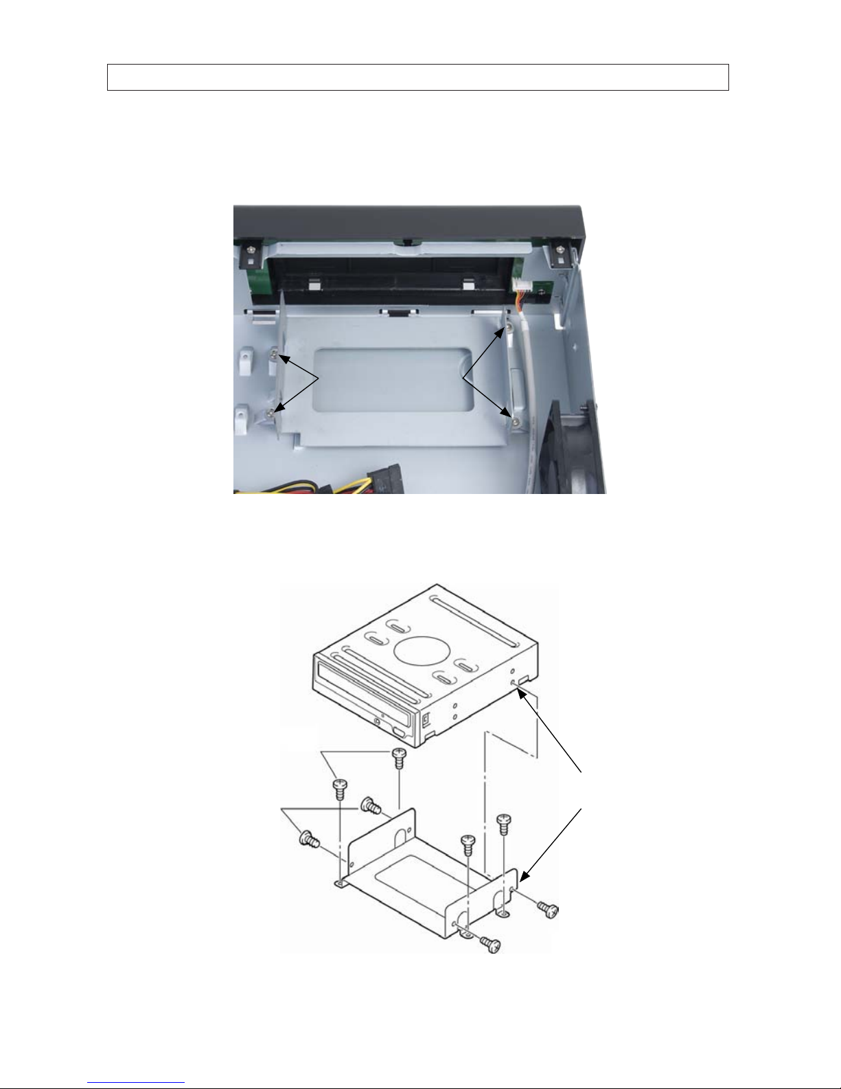
4. Remove the DVD-R/W mounting bracket from the DVD-R/W drive bay by removing the four screws that secure it to the
chassis. Note that the bracket mounting screws near the side of the chassis are spaced further apart than the screws near the
middle of the chassis.
Mounting bracket screws
5. Secure the DVD-R/W drive to the mounting bracket using four screws, two on each side, provided in the hardware kit. Orient
the drive so it will point to the front of the DVR, and it is positioned properly in the mounting bracket (see the NOTE in the
illustration below).
Front
Bracket to chassis
mounting screws
Bracket to DVD
drive mounting
screws
NOTE: Use these
screw holes for
proper positioning

18
SECTION 2: HARDWARE OVERVIEW AND SETUP
6. Reinstall the DVD mounting bracket with the DVD drive in the chassis using the four screws removed earlier.
7. Plug a SATA power cable from the cable bundle into the mating connector of the DVD drive.
8. Plug a SATA data cable to the back of the DVD drive. Plug the other end of the cable into a SATA connector on the PC board.
NOTE
SATA data interfaces on the PC board are labeled HDD1, HDD2, HDD3, etc. Not all are connectorized. Always use the lowest
numbered connectorized SATA data interfaces for the HDD drives in the DVR, and a higher numbered connector for the DVD drive.
For example, if HDD1 is not connectorized, but HDD2, HDD3 and HDD4 are, and two HDD drives are (or will be) installed in the
DVR, use HDD2 for the primary HDD drive, HDD3 for the secondary HDD drive, and HDD4 for the DVD-R/W drive. Connector labels
are marked on the PC board.
In the following example, HDD1 is not connectorized, an HDD drive data cable is plugged into HDD2, and the DVD-R/W drive
data cable is plugged into HDD3.
SATA
power
cable
DVD-R/W
SATA data
cable
HDD2 connector (HDD)
HDD3 connector (DVD R/W)
9. If you are installing HDD(s) in the DVR at this time, continue with “2.5.4 BLK-HD10D, BLK-HD16D HDD installation” on page 24.
Otherwise, go to “SECTION 3 System Setup” on page 28.

19H.264 High Denition DVR User Manual
SECTION 2: HARDWARE OVERVIEW AND SETUP
2.5 HDD installation
When choosing an HDD to install, select one from the list provided in “APPENDIX A DVR Compatible Hard Disk Drives” on page 113 to
ensure the best performance
2.5.1 HDD recording capacities
Interpolate the information provided in the tables below to estimate the recording capacity of your HDD and determine what
capacity of HDD will meet your recording requirements.
If installing more than one HDD in your DVR, each must be the of same brand and model. Otherwise, an HDD may not be recognized
by the DVR and can malfunction.
Recording mode: 4-channels, continuous, 1280 x 720 @ 30 fps, audio on
HDD
Capacity
Level 5 (high) Level 4 Level 3 Level 2 Level 1 (low)
days hours days hours days hours days hou rs days hou rs
250GB 0 22 1 3 1 12 1 20 2 6
320GB 1 5 1 12 2 0 2 9 3 23
500GB 1 22 2 10 3 5 3 20 4 18
1TB 4 23 5 2 3 6 14 7 21 9 18
1.5TB 6 0 7 12 10 22 11 21 14 18
2TB 8 1 10 1 13 7 15 22 19 18
Recording mode: 4-channels, continuous, 640 x 360 @ 30 fps, audio on
HDD
Capacity
Level 5 (high) Level 4 Level 3 Level 2 Level 1 (low)
days hours days hours days hours days hou rs days hou rs
250GB 1 20 2 7 3 1 3 16 4 13
320GB 2 10 3 0 4 0 4 19 6 2 3
500GB 3 21 4 20 6 10 7 16 9 13
1TB 8 23 9 2 2 13 4 15 17 19 13
1.5TB 12 1 15 0 19 21 23 19 29 13
2TB 16 2 20 2 26 15 31 20 39 13
20
SECTION 2: HARDWARE OVERVIEW AND SETUP
2.5.2 BLK-HD4D, BLK-HD8D HDD installation
The HDD is used to store video and snapshots recorded by the DVR. Normally, DVRs have one internal HDD and one internal
DVD-R/W drive. However, a second internal HDD can be installed in place of the DVD drive, if needed.
Your DVR will accommodate one standard-size desktop system HDD with a SATA interface. If your DVR was purchased without an
HDD, a hardware kit, including mounting brackets, screws and cables is included with the DVR.
For attaching bracket
to DVD-R/W (at-head,
ne-thread screws (4))
For attaching bracket to
HDD (pan-head, medium-
thread screws (4))
For attaching bracket
to chassis (pan-head,
course-thread screws)
Mounting Brackets (one pair per drive) Screw types
To install an HDD, carefully follow the procedure below.
CAUTION
Follow recommended electrostatic discharge (ESD) guidelines while performing this procedure. Install the HDD in a static-free
environment, wearing a certied ESD wrist strap. If a static free environment and ESD wrist strap is not available, touch the bare
metal of the DVR chassis frequently when installing the drive to dissipate the static charge naturally generated on your skin and
clothing.
1. If your DVR is powered on, use the menu system to perform a System Shutdown.
a. Right click anywhere on the live view screen, then click SYSTEM SHUTDOWN in the pop-up menu (see “SECTION 3
System Setup” on page 28), or click the SYSTEM SHUTDOWN icon on the task bar.
b. Follow the on-screen instructions for shutting down the system.
2. Disconnect the power adapter from the back of the DVR.
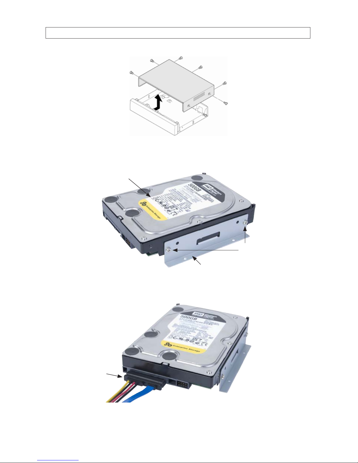
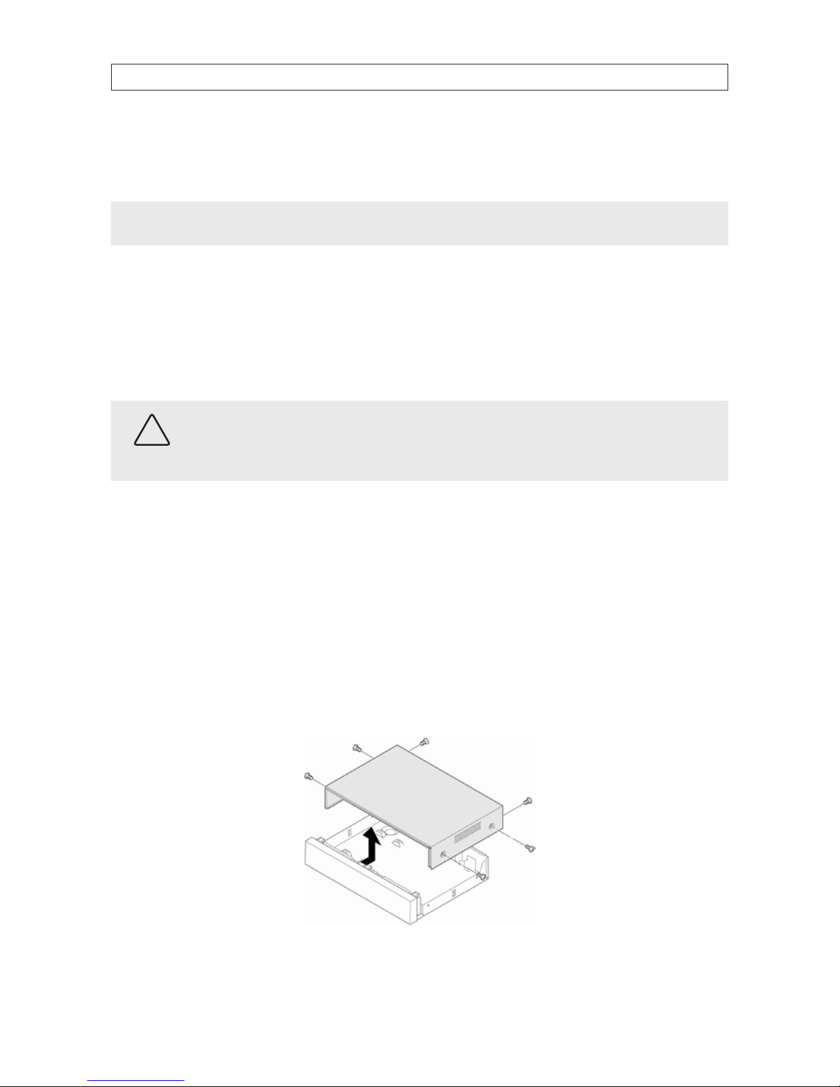
3. Remove the top cover from the DVR by removing the three cover screws on the back of the chassis, and the two on each side.
See the drawing below.
21H.264 High Denition DVR User Manual
SECTION 2: HARDWARE OVERVIEW AND SETUP
4. Attach a mounting bracket to each side of the HDD as shown below using the pan-head medium- thread screws provided.
Use two screws for each bracket. Tighten the screws until snug.
HDD
Mounting bracket
Pan-head mediumthread screws (2)
5. Plug a SATA data and power cable assembly into the mating connectors on the back of the HDD. Ensure the connector is fully
seated.
SATA data and
power cable
22
SECTION 2: HARDWARE OVERVIEW AND SETUP
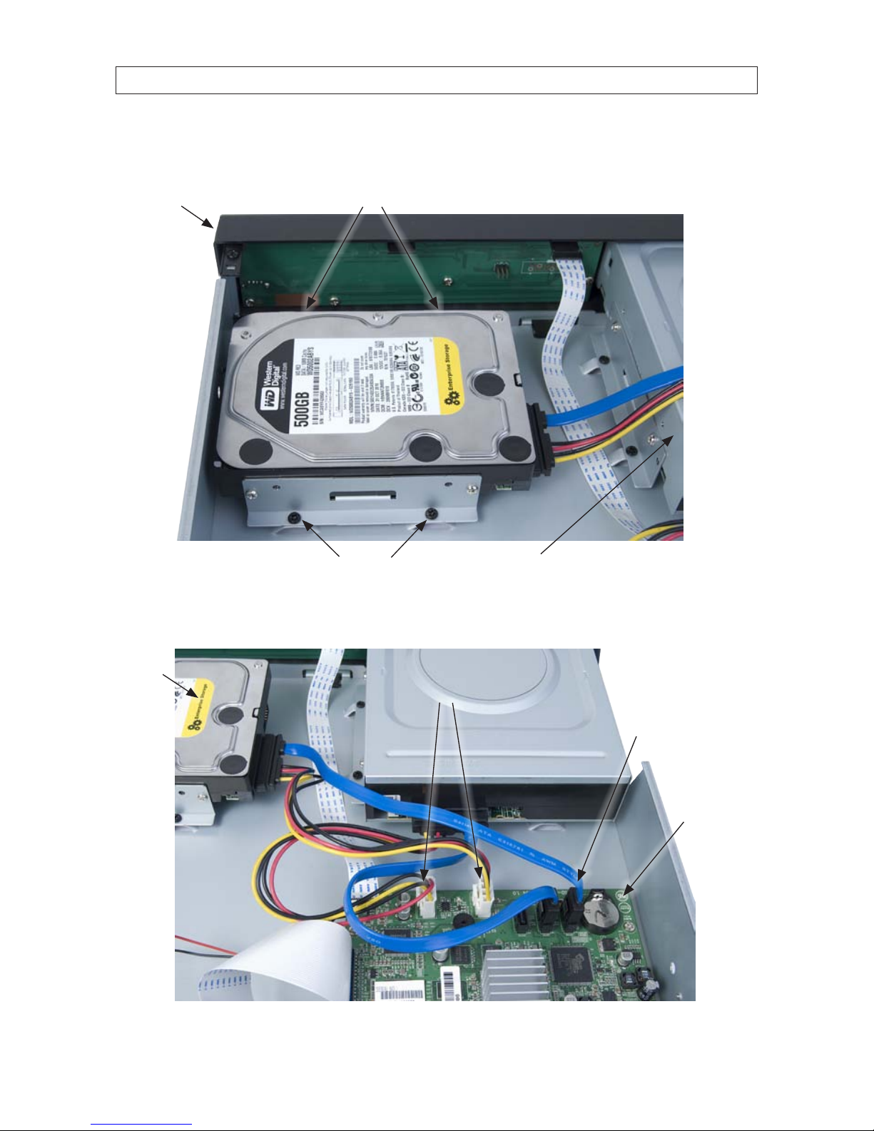
6. Position the HDD into the HDD bay as shown below. Secure the drive to the chassis with four screws through the mounting
brackets, two on each side of the HDD. Use black pan-head course-thread screws provided. Tighten the screws until snug.
Screws (2) between HDD and DVR front panel
Screws
DVR front panel
DVD-R/W drive
7. Plug the SATA data cable (blue cable) into the SATA0 connector on the PC board, then plug the SATA power cable into one of
the SATA power connectors on the PC board.
SATA0
connector
SATA power connectors
PC board
HDD
23H.264 High Denition DVR User Manual
SECTION 2: HARDWARE OVERVIEW AND SETUP
Ensure that the data and power cable connectors are fully seated onto the connectors on the PC board.
8. Reinstall the DVR cover using the 7 screws removed earlier.
9. Reattach the power adapter to the back of the DVR.
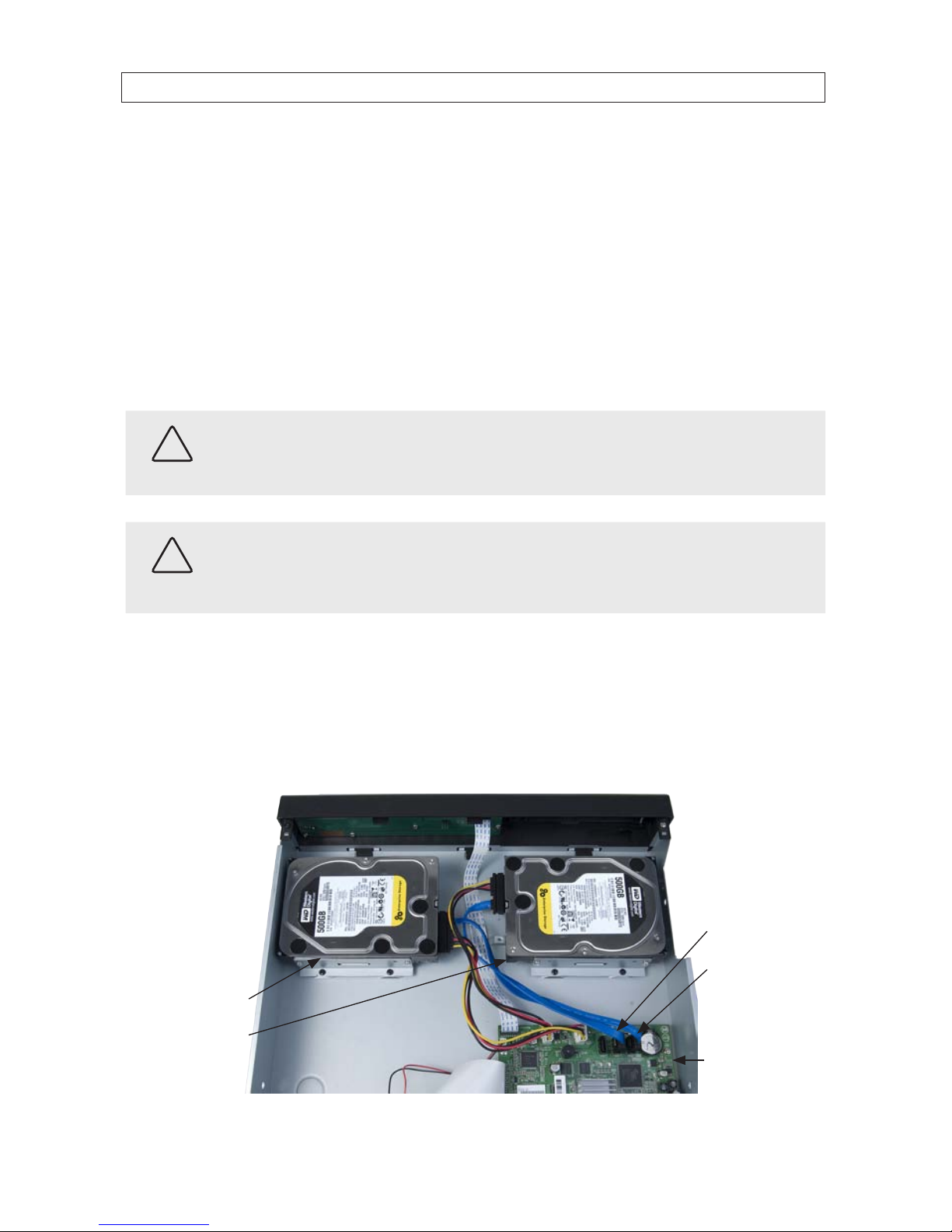
2.5.3 BLK-HD4D, BLK-HD8D Installing a 2nd internal HDD
The DVR can include two internal HDDs, with the second HDD installed in the DVD-R/W (optical) drive bay. To install a 2nd HDD, do
the following.
CAUTION
If installing 2 HDDs into your DVR, always install HDDs of the same brand and model. If you install dierent HDDs, the DVR may
not recognize an HDD and can malfunction.
CAUTION
Follow recommended electrostatic discharge (ESD) guidelines while performing this procedure. Install the HDD in a static-free
environment, wearing a certied ESD wrist strap. If a static free environment and ESD wrist strap is not available, touch the bare
metal of the DVR chassis frequently when installing the drive to dissipate the static charge naturally generated on your skin and
clothing.
1. If a DVD-RW drive is installed in the optical drive bay, remove it by reversing the procedure included above in “2.4 DVD-R/W
Optical drive installation” on page 11.
2. Attach the mounting brackets and data/power cable to the 2nd HDD. See “2.5 HDD installation” on page 15 above.
3. Position the HDD in the optical bay as shown below, and attach it to the chassis using 4 screws, 2 on each side.
SATA1 connector
SATA0 connector
Primary HDD
Secondary HDD
PC board
24
SECTION 2: HARDWARE OVERVIEW AND SETUP
4. Connect the HDD SATA data cable (blue) to the SATA1 connector on the PC board.
5. Connect the HDD SATA power cable to one of the mating connectors on the PC board.
NOTE
In a DVR with 2 HDDs, the primary HDD is connected to the SATA0 connector and the secondary HDD is connected to the SATA1
connector.
2.5.4 BLK-HD10D, BLK-HD16D HDD installation
Your DVR will accommodate standard desktop system HDDs with a SATA interfaces. If installing more than one HDD in your DVR,
they may must be the same brand and model. If your DVR was purchased without an HDD, a hardware kit is included with the DVR.
To install an HDD, carefully follow the procedure below.
CAUTION
Follow recommended electrostatic discharge (ESD) guidelines while performing this procedure. Install the HDD in a static-free
environment, wearing a certied ESD wrist strap. If a static free environment and ESD wrist strap is not available, touch the bare
metal of the DVR chassis frequently when installing the drive to dissipate the static charge naturally generated on your skin and
clothing.
1. If your DVR is powered on, use the menu system to perform a System Shutdown.
a. Right click anywhere on the live view screen, then click SYSTEM SHUTDOWN in the pop-up menu (see “SECTION 3
System Setup” on page 28), or click the SYSTEM SHUTDOWN icon on the task bar.
b. Follow the on-screen instructions for shutting down the system.
2. Disconnect the power cord from the back of the DVR.
3. Remove the top cover from the DVR by removing the two cover screws on the back of the chassis, and the two on each side.
See the drawing below.
 Loading...