

Observint Technologies BLK-DH200400D, BLK-DH200800D, BLK-DH201600D User Manual

H.264 4/8/16-Channel DVR
User Manual
Products: BLK-DH200400D, BLK-DH200800D, BLK-DH201600D
PLEASE READ THIS MANUAL BEFORE USING YOUR RECORDER, and always follow the
instructions for safety and proper use. Save this manual for future reference.
BLK-DH20xx00D_RM
8/3/11
Operate this system onl y in environments where the temperature and h umidity is within the recommend ed range.
CAUTION
LEGAL NOTIC E
DIGIOP™ products are designed to meet safety and performance standards with the use of specic DIGIOP
authorized accessories. DIGIOP disclaims liability associated with the use of non-DIGIOP authorized accessories.
The recording, transmission, or broadcast of any person’s voice without their consent or a court order is strictly
prohibited by law.
DIGIOP makes no representations concerning the legality of certain product applications such as the making,
transmission, or recording of video and/or audio signals of others without their knowledge and/or consent. We
encourage you to check and comply with all applicable local, state, and federal laws and regulations before
engaging in any form of sur veillance or any transmission of radio frequencies.
Micro soft, Win dows, Window s Media, and In ternet Exp lorer are either registered trademarks or trademark s of Microsoft
Corporation in the United States and/or other countries. Andr oid is a trademark of Google Inc. Use of this trademark
is subject to Google Permissions. Apple, iPh one, iPod touc h, and iPad are registered trademarks of Apple Inc. Intel and P entium
are trademarks of Intel Corporation in the U.S. and/or other countries.
Other trademarks and trade names may be used in this document to refer to either the entities claiming the mark s
and names or their products. DIGIOP, Inc. disclaims any proprietary interest in trademarks and trade names other
than its own.
No part of this document may be reproduced or distributed in any form or by any means without the express written
permission of DIGIOP, Inc.
Operation in temp eratures or at humidity levels out side the recommended range may cause elect ric shock and shorten the
life of the produc t. Refer to the specications for each sy stem component for more inform ation.
© 2011 by DIGIOP, Inc. All Rights Res erved.
3850 Priorit y Way South Drive, Suite 200, Indianapolis, IN 46240
Sales/Support: 1.877.972.2522
ii
www.digiop.com

Table of Contents
SECTION 1 Introduction . . . . . . . . . . . . . . . . . . . . . . . . . . . . . . . . . . . . . . . . . . . . . . . . . . . . . . . . . . . . . . . . . . . . . . . 1
SECTION 2 Hardware Overview . . . . . . . . . . . . . . . . . . . . . . . . . . . . . . . . . . . . . . . . . . . . . . . . . . . . . . . . . . . . . . . . . 2
2.1 Front panel . . . . . . . . . . . . . . . . . . . . . . . . . . . . . . . . . . . . . . . . . . . . . . . . . . . . . . . . . . . . . . . . . . . . . . . . .2
2.2 Rear panel . . . . . . . . . . . . . . . . . . . . . . . . . . . . . . . . . . . . . . . . . . . . . . . . . . . . . . . . . . . . . . . . . . . . . . . . . . 4
2.3 Remote Control . . . . . . . . . . . . . . . . . . . . . . . . . . . . . . . . . . . . . . . . . . . . . . . . . . . . . . . . . . . . . . . . . . . . . . 5
SECTION 3 System Setup . . . . . . . . . . . . . . . . . . . . . . . . . . . . . . . . . . . . . . . . . . . . . . . . . . . . . . . . . . . . . . . . . . . . . . . 7
3.1 Starting the system for the rst time . . . . . . . . . . . . . . . . . . . . . . . . . . . . . . . . . . . . . . . . . . . . . . . . . . . . 7
3.1.1 Entering the SETUP menu . . . . . . . . . . . . . . . . . . . . . . . . . . . . . . . . . . . . . . . . . . . . . . . . . . . . . . . . .8
3.2 DISPLAY menu . . . . . . . . . . . . . . . . . . . . . . . . . . . . . . . . . . . . . . . . . . . . . . . . . . . . . . . . . . . . . . . . . . . . . .10
3.3 RECORD menu . . . . . . . . . . . . . . . . . . . . . . . . . . . . . . . . . . . . . . . . . . . . . . . . . . . . . . . . . . . . . . . . . . . . . .11
3.3.1 Recording Schedules . . . . . . . . . . . . . . . . . . . . . . . . . . . . . . . . . . . . . . . . . . . . . . . . . . . . . . . . . . . .13
3.4 DEVICE menu . . . . . . . . . . . . . . . . . . . . . . . . . . . . . . . . . . . . . . . . . . . . . . . . . . . . . . . . . . . . . . . . . . . . . . .14
3.4.1 ALARM OUT submenu . . . . . . . . . . . . . . . . . . . . . . . . . . . . . . . . . . . . . . . . . . . . . . . . . . . . . . . . . . .15
3.4.2 SPOT-OUT setup . . . . . . . . . . . . . . . . . . . . . . . . . . . . . . . . . . . . . . . . . . . . . . . . . . . . . . . . . . . . . . . .16
3.4.3 PTZ Setup . . . . . . . . . . . . . . . . . . . . . . . . . . . . . . . . . . . . . . . . . . . . . . . . . . . . . . . . . . . . . . . . . . . . .16
3.4.4 MOTION ZONE Setup . . . . . . . . . . . . . . . . . . . . . . . . . . . . . . . . . . . . . . . . . . . . . . . . . . . . . . . . . . . . 17
3.5 STORAGE menu . . . . . . . . . . . . . . . . . . . . . . . . . . . . . . . . . . . . . . . . . . . . . . . . . . . . . . . . . . . . . . . . . . . . .18
3.6 SYSTEM menu . . . . . . . . . . . . . . . . . . . . . . . . . . . . . . . . . . . . . . . . . . . . . . . . . . . . . . . . . . . . . . . . . . . . . .19
3.7 SECURITY menu. . . . . . . . . . . . . . . . . . . . . . . . . . . . . . . . . . . . . . . . . . . . . . . . . . . . . . . . . . . . . . . . . . . . .22
3.8 NETWORK menu . . . . . . . . . . . . . . . . . . . . . . . . . . . . . . . . . . . . . . . . . . . . . . . . . . . . . . . . . . . . . . . . . . . .23
3.8.1 DHCP networks . . . . . . . . . . . . . . . . . . . . . . . . . . . . . . . . . . . . . . . . . . . . . . . . . . . . . . . . . . . . . . . . .25
3.8.2 ADSL (PPPoE) networks. . . . . . . . . . . . . . . . . . . . . . . . . . . . . . . . . . . . . . . . . . . . . . . . . . . . . . . . . .25
3.8.3 LAN networks . . . . . . . . . . . . . . . . . . . . . . . . . . . . . . . . . . . . . . . . . . . . . . . . . . . . . . . . . . . . . . . . . .26
3.8.4 DDNS option . . . . . . . . . . . . . . . . . . . . . . . . . . . . . . . . . . . . . . . . . . . . . . . . . . . . . . . . . . . . . . . . . . .26
3.8.5 Network ports . . . . . . . . . . . . . . . . . . . . . . . . . . . . . . . . . . . . . . . . . . . . . . . . . . . . . . . . . . . . . . . . .27
3.8.6 Network stream . . . . . . . . . . . . . . . . . . . . . . . . . . . . . . . . . . . . . . . . . . . . . . . . . . . . . . . . . . . . . . . .28
3.8.7 CONFIG menu . . . . . . . . . . . . . . . . . . . . . . . . . . . . . . . . . . . . . . . . . . . . . . . . . . . . . . . . . . . . . . . . . .28
3.9 Save setup . . . . . . . . . . . . . . . . . . . . . . . . . . . . . . . . . . . . . . . . . . . . . . . . . . . . . . . . . . . . . . . . . . . . . . . . .30
SECTION 4 Live, Search, and Playback . . . . . . . . . . . . . . . . . . . . . . . . . . . . . . . . . . . . . . . . . . . . . . . . . . . . . . . . . . . 31
4.1 SEARCH menu . . . . . . . . . . . . . . . . . . . . . . . . . . . . . . . . . . . . . . . . . . . . . . . . . . . . . . . . . . . . . . . . . . . . . .33
4.1.1 TIME-LINE search . . . . . . . . . . . . . . . . . . . . . . . . . . . . . . . . . . . . . . . . . . . . . . . . . . . . . . . . . . . . . . .34
4.1.2 EVENT search . . . . . . . . . . . . . . . . . . . . . . . . . . . . . . . . . . . . . . . . . . . . . . . . . . . . . . . . . . . . . . . . . .35
4.1.3 GO TO FIRST TIME search . . . . . . . . . . . . . . . . . . . . . . . . . . . . . . . . . . . . . . . . . . . . . . . . . . . . . . . . .36
4.1.4 GO TO LAST TIME search. . . . . . . . . . . . . . . . . . . . . . . . . . . . . . . . . . . . . . . . . . . . . . . . . . . . . . . . . .36
4.1.5 GO TO SPECIFIC TIME search . . . . . . . . . . . . . . . . . . . . . . . . . . . . . . . . . . . . . . . . . . . . . . . . . . . . . .36
4.2 ARCHIVE search . . . . . . . . . . . . . . . . . . . . . . . . . . . . . . . . . . . . . . . . . . . . . . . . . . . . . . . . . . . . . . . . . . . .36
4.3 PLAY mode . . . . . . . . . . . . . . . . . . . . . . . . . . . . . . . . . . . . . . . . . . . . . . . . . . . . . . . . . . . . . . . . . . . . . . . . .37
iiiH.264 DVR User Manual

SECTION 5 PTZ Control . . . . . . . . . . . . . . . . . . . . . . . . . . . . . . . . . . . . . . . . . . . . . . . . . . . . . . . . . . . . . . . . . . . . . . . . 39
SECTION 6 Backup . . . . . . . . . . . . . . . . . . . . . . . . . . . . . . . . . . . . . . . . . . . . . . . . . . . . . . . . . . . . . . . . . . . . . . . . . . . 40
6.1 Still image backup onto USB ash drive . . . . . . . . . . . . . . . . . . . . . . . . . . . . . . . . . . . . . . . . . . . . . . . .40
6.2 Video backup onto USB ash drive . . . . . . . . . . . . . . . . . . . . . . . . . . . . . . . . . . . . . . . . . . . . . . . . . . . . .40
6.3 Copy still images or video from the ARCHIVE list . . . . . . . . . . . . . . . . . . . . . . . . . . . . . . . . . . . . . . . . .41
6.4 Playing backed up video clips . . . . . . . . . . . . . . . . . . . . . . . . . . . . . . . . . . . . . . . . . . . . . . . . . . . . . . . . .42
SECTION 7 Firmware Upgrade . . . . . . . . . . . . . . . . . . . . . . . . . . . . . . . . . . . . . . . . . . . . . . . . . . . . . . . . . . . . . . . . . 43
SECTION 8 UMS Single Client Software . . . . . . . . . . . . . . . . . . . . . . . . . . . . . . . . . . . . . . . . . . . . . . . . . . . . . . . . . . 45
8.1 PC Requirements . . . . . . . . . . . . . . . . . . . . . . . . . . . . . . . . . . . . . . . . . . . . . . . . . . . . . . . . . . . . . . . . . . . .45
8.2 Installing the UMS Single Client . . . . . . . . . . . . . . . . . . . . . . . . . . . . . . . . . . . . . . . . . . . . . . . . . . . . . . .45
8.3 UMS Single Client initial display . . . . . . . . . . . . . . . . . . . . . . . . . . . . . . . . . . . . . . . . . . . . . . . . . . . . . . .46
8.4 Setup . . . . . . . . . . . . . . . . . . . . . . . . . . . . . . . . . . . . . . . . . . . . . . . . . . . . . . . . . . . . . . . . . . . . . . . . . . . . .48
8.4.1 General Setup . . . . . . . . . . . . . . . . . . . . . . . . . . . . . . . . . . . . . . . . . . . . . . . . . . . . . . . . . . . . . . . . . . 48
8.4.2 Site Setup . . . . . . . . . . . . . . . . . . . . . . . . . . . . . . . . . . . . . . . . . . . . . . . . . . . . . . . . . . . . . . . . . . . . . 49
8.4.3 Event Setup . . . . . . . . . . . . . . . . . . . . . . . . . . . . . . . . . . . . . . . . . . . . . . . . . . . . . . . . . . . . . . . . . . . .50
8.4.4 Event Search Setup . . . . . . . . . . . . . . . . . . . . . . . . . . . . . . . . . . . . . . . . . . . . . . . . . . . . . . . . . . . . . 51
8.4.5 Record Setup . . . . . . . . . . . . . . . . . . . . . . . . . . . . . . . . . . . . . . . . . . . . . . . . . . . . . . . . . . . . . . . . . .52
8.4.6 Record Disk Setup . . . . . . . . . . . . . . . . . . . . . . . . . . . . . . . . . . . . . . . . . . . . . . . . . . . . . . . . . . . . . .52
8.4.7 Language Setup . . . . . . . . . . . . . . . . . . . . . . . . . . . . . . . . . . . . . . . . . . . . . . . . . . . . . . . . . . . . . . . .53
8.5 Connecting to a DVR . . . . . . . . . . . . . . . . . . . . . . . . . . . . . . . . . . . . . . . . . . . . . . . . . . . . . . . . . . . . . . . . . 53
8.5.1 Bidirectional Audio . . . . . . . . . . . . . . . . . . . . . . . . . . . . . . . . . . . . . . . . . . . . . . . . . . . . . . . . . . . . .54
8.6 Remote Search mode and functions . . . . . . . . . . . . . . . . . . . . . . . . . . . . . . . . . . . . . . . . . . . . . . . . . . .54
8.6.1 Searching for and playing video recorded by the DVR . . . . . . . . . . . . . . . . . . . . . . . . . . . . . . . .56
8.6.2 Backing up video from the DVR on the UMS Single Client PC . . . . . . . . . . . . . . . . . . . . . . . . . . .57
8.6.3 Image capture . . . . . . . . . . . . . . . . . . . . . . . . . . . . . . . . . . . . . . . . . . . . . . . . . . . . . . . . . . . . . . . . .59
SECTION 9 UMS Multi Client Soft ware . . . . . . . . . . . . . . . . . . . . . . . . . . . . . . . . . . . . . . . . . . . . . . . . . . . . . . . . . . 60
9.1 PC Requirements . . . . . . . . . . . . . . . . . . . . . . . . . . . . . . . . . . . . . . . . . . . . . . . . . . . . . . . . . . . . . . . . . . . .60
9.2 Installing the UMS Multi Client . . . . . . . . . . . . . . . . . . . . . . . . . . . . . . . . . . . . . . . . . . . . . . . . . . . . . . . .60
9.3 UMS Multi Client initial display . . . . . . . . . . . . . . . . . . . . . . . . . . . . . . . . . . . . . . . . . . . . . . . . . . . . . . . . 61
9.4 Setup . . . . . . . . . . . . . . . . . . . . . . . . . . . . . . . . . . . . . . . . . . . . . . . . . . . . . . . . . . . . . . . . . . . . . . . . . . . . .63
9.4.1 General Setup . . . . . . . . . . . . . . . . . . . . . . . . . . . . . . . . . . . . . . . . . . . . . . . . . . . . . . . . . . . . . . . . . . 63
9.4.2 Event Setup . . . . . . . . . . . . . . . . . . . . . . . . . . . . . . . . . . . . . . . . . . . . . . . . . . . . . . . . . . . . . . . . . . . .64
9.4.3 Event Search Setup . . . . . . . . . . . . . . . . . . . . . . . . . . . . . . . . . . . . . . . . . . . . . . . . . . . . . . . . . . . . . 65
9.4.4 Record Setup . . . . . . . . . . . . . . . . . . . . . . . . . . . . . . . . . . . . . . . . . . . . . . . . . . . . . . . . . . . . . . . . . .65
9.4.5 Record Disk Setup . . . . . . . . . . . . . . . . . . . . . . . . . . . . . . . . . . . . . . . . . . . . . . . . . . . . . . . . . . . . . .66
iv
www.digiop.com

9.4.6 OSD Setup . . . . . . . . . . . . . . . . . . . . . . . . . . . . . . . . . . . . . . . . . . . . . . . . . . . . . . . . . . . . . . . . . . . . .67
9.4.7 Language Setup . . . . . . . . . . . . . . . . . . . . . . . . . . . . . . . . . . . . . . . . . . . . . . . . . . . . . . . . . . . . . . . .67
9.5 Connecting to a DVR . . . . . . . . . . . . . . . . . . . . . . . . . . . . . . . . . . . . . . . . . . . . . . . . . . . . . . . . . . . . . . . . . 67
9.5.1 Bidirectional Audio . . . . . . . . . . . . . . . . . . . . . . . . . . . . . . . . . . . . . . . . . . . . . . . . . . . . . . . . . . . . .69
9.5.2 Capture . . . . . . . . . . . . . . . . . . . . . . . . . . . . . . . . . . . . . . . . . . . . . . . . . . . . . . . . . . . . . . . . . . . . . . .69
9.5.3 Record . . . . . . . . . . . . . . . . . . . . . . . . . . . . . . . . . . . . . . . . . . . . . . . . . . . . . . . . . . . . . . . . . . . . . . . .70
9.6 Remote playback and backup . . . . . . . . . . . . . . . . . . . . . . . . . . . . . . . . . . . . . . . . . . . . . . . . . . . . . . . . .70
9.6.1 Remote playback . . . . . . . . . . . . . . . . . . . . . . . . . . . . . . . . . . . . . . . . . . . . . . . . . . . . . . . . . . . . . . .70
9.6.2 Backing up video from the DVR on the UMS Multi Client PC . . . . . . . . . . . . . . . . . . . . . . . . . . . 72
9.7 Local playback . . . . . . . . . . . . . . . . . . . . . . . . . . . . . . . . . . . . . . . . . . . . . . . . . . . . . . . . . . . . . . . . . . . . . .74
9.7.1 AVI backup during playback . . . . . . . . . . . . . . . . . . . . . . . . . . . . . . . . . . . . . . . . . . . . . . . . . . . . .75
SECTION 10 WebViewer . . . . . . . . . . . . . . . . . . . . . . . . . . . . . . . . . . . . . . . . . . . . . . . . . . . . . . . . . . . . . . . . . . . . . . . . 77
10.1 Connecting to the DVR with IE . . . . . . . . . . . . . . . . . . . . . . . . . . . . . . . . . . . . . . . . . . . . . . . . . . . . . . . .77
10.2 Setup . . . . . . . . . . . . . . . . . . . . . . . . . . . . . . . . . . . . . . . . . . . . . . . . . . . . . . . . . . . . . . . . . . . . . . . . . . . . .82
10.2.1 Setup Display . . . . . . . . . . . . . . . . . . . . . . . . . . . . . . . . . . . . . . . . . . . . . . . . . . . . . . . . . . . . . . . . . .82
10.2.2 Setup Record . . . . . . . . . . . . . . . . . . . . . . . . . . . . . . . . . . . . . . . . . . . . . . . . . . . . . . . . . . . . . . . . . .83
10.2.3 Setup Device . . . . . . . . . . . . . . . . . . . . . . . . . . . . . . . . . . . . . . . . . . . . . . . . . . . . . . . . . . . . . . . . . . .83
10.2.4 Setup Storage . . . . . . . . . . . . . . . . . . . . . . . . . . . . . . . . . . . . . . . . . . . . . . . . . . . . . . . . . . . . . . . . . .85
10.2.5 Setup System . . . . . . . . . . . . . . . . . . . . . . . . . . . . . . . . . . . . . . . . . . . . . . . . . . . . . . . . . . . . . . . . . .85
10.2.6 Setup Security . . . . . . . . . . . . . . . . . . . . . . . . . . . . . . . . . . . . . . . . . . . . . . . . . . . . . . . . . . . . . . . . .87
10.2.7 Setup Network . . . . . . . . . . . . . . . . . . . . . . . . . . . . . . . . . . . . . . . . . . . . . . . . . . . . . . . . . . . . . . . . .88
10.3 DVR Search. . . . . . . . . . . . . . . . . . . . . . . . . . . . . . . . . . . . . . . . . . . . . . . . . . . . . . . . . . . . . . . . . . . . . . . . .88
10.3.1 Playing recorded video . . . . . . . . . . . . . . . . . . . . . . . . . . . . . . . . . . . . . . . . . . . . . . . . . . . . . . . . . .90
10.4 Backup recorded video . . . . . . . . . . . . . . . . . . . . . . . . . . . . . . . . . . . . . . . . . . . . . . . . . . . . . . . . . . . . . . .90
10.4.1 Capture . . . . . . . . . . . . . . . . . . . . . . . . . . . . . . . . . . . . . . . . . . . . . . . . . . . . . . . . . . . . . . . . . . . . . . . 91
SECTION 11 Specications . . . . . . . . . . . . . . . . . . . . . . . . . . . . . . . . . . . . . . . . . . . . . . . . . . . . . . . . . . . . . . . . . . . . . 92
APPENDIX A HDD Replacement . . . . . . . . . . . . . . . . . . . . . . . . . . . . . . . . . . . . . . . . . . . . . . . . . . . . . . . . . . . . . . . . . . 94
APPENDIX B Device Log . . . . . . . . . . . . . . . . . . . . . . . . . . . . . . . . . . . . . . . . . . . . . . . . . . . . . . . . . . . . . . . . . . . . . . . . 97
APPENDIX C DVR Setup Menu Components . . . . . . . . . . . . . . . . . . . . . . . . . . . . . . . . . . . . . . . . . . . . . . . . . . . . . . . 98
vH.264 DVR User Manual

vi
www.digiop.com

SECTION 1: INTRODUCTION
SECTION 1
Introduction
Features
• H.264 Video Compression
• Reliable File System
• Live and Event Pop-up
• VGA display interface (1280 x 1024)
• 4 Channel Audio Recording
• Bidirectional Audio
• Individual Channel Operation
• Motion Detec tion
• Automatic Video Input and Video Loss Detection
• Covert Camera O peration Provides Enhanced Security
• Built-In PTZ Camera Control
• User friendly operator inter face
• Record scheduler
• Soft ware upgradable
• Backup via USB ash drive, Network or DVD-R/W
• Exclusive le format backup
• AVI backup
• Network Access via WebViewer (embedded brows er-based client), UMS Client (for monitoring a single DVR), UMS Multi Client
(for monitoring mult iple DVRs concurrently), and smartphone apps for Apple® iPhone® and Android™.
Your DVR include s:
• DVR with DVD-R/W drive and hard disk drive (HDD)
• Soft ware CD containing the UMS Client, UMS Multi Client, and the DVR user manual (this do cument)
• Remote Control
• Batter y 1.5V (2 x AAA)
• Power Adaptor (12VDC, 5A) and cable
• Mouse
• Quick Start Guide document
1H.264 DVR User Manual
SECTION 2: HARDWARE OVERVIEW
SECTION 2
Hardware Overview
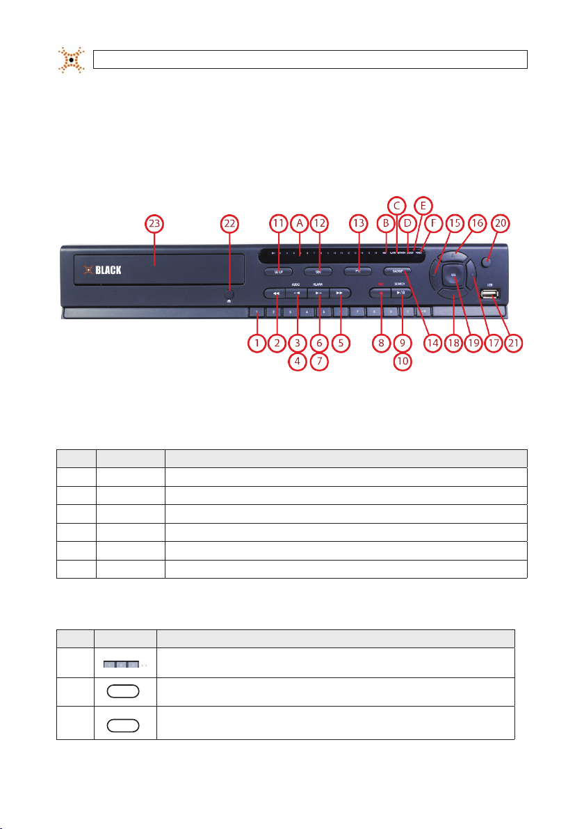
2.1 Front panel
4/8/16 Channel DVR Front Panel
Table 1. Front Panel LED Indicators
No. Name Descr iption
A CH1~16 Indicate s that the chann el is being recor ded.
B HDD Indicate s that the sys tem is accessing t he hard disk.
C AL ARM Indicate s when a sensor i s triggered o r motion is dete cted.
D NETWO RK Indicate s that a netwo rk client is conne cted.
E B ACKUP Indicates tha t a USB or DVD-R/ W storage dev ice is storing im ages or video.
F POWER In dicates that t he system is sw itched on.
Table 2. Front Panel Buttons
No. Name Descr iption
1
2
3
2
AUDIO
..
www.digiop.com
Channel key s. For channel 10, p ress the 0 key. For cha nnel 11, press the +10 and 1 key. For channe l 16, press the +10
and 6 key.
Press to re wind the vide o in playback mod e.
Press to se lect audio mo de such as SINGLE ( highlighted ch annel), MIX (combine all c hannels), or MUTE (all chann els).

No. Name Descr iption
AUDIO
4
5
6
7
8
9
10
11
12
13
14
15
16
17
18
19
20
21 USB Port
..
ALARM
..
ALARM
..
REC
SEARCH
/ ll
SEARCH
/ ll
SETUP
SEQ
PTZ
BACKUP
t (LEFT )
p (UP)
u (RIGHT)
q (DOWN)
SEL
ESC
Jump/step b ackward. In pla yback mode, th e playback posi tion moves 60 s econds back ward.
Press to f ast forwar d the footage i n playback mode.
Press to en able/disable AL ARM operati on.
Jump/Step f orward. In play back mode, the p layback posit ion moves 60 se conds forw ard.
Press to s tart or stop m anual recordin g.
Press to op en the SEARCH me nu in live display mo de.
Press to pl ay/pause the recor ding in playback m ode.
Press to en ter SETUP menu.
Enable/dis able the autom atic sequence d isplay of channels i n full screen, q uad-split, an d 9-split disp lay mode.
Press to co ntrol Pan/Ti lt/Zoom ope rations.
Press to c apture live or play back mode vide o in JPEG forma t.
Press to mo ve left or to cha nge the values in S etup mode. Wh en entering a pas sword, it inser ts a 4.
Press to mo ve up the menu in Set up mode. When ent ering a passwo rd, it insert s a 1.
Press to mo ve right or to chang e the values in Se tup mode. When e ntering a pass word, it inser ts a 2.
Press to mo ve down the menu in S etup mode. Whe n entering a pass word, it inser ts a 3.
Press to se lect desir ed menu item or to s tore the setup v alue.
Press fo r temporary s torage of the ch anged value or to r eturn to the pre vious menu scr een.
Use with a US B ash drive to arch ive still image s and videos, and u pgrade rmwa re, or use to conne ct a USB mouse to
the DVR.
SECTION 2: HARDWARE OVERVIEW
22
To open and clo se the inser t tray, press the bu tton
23 DVD Drive To save video, inser t a CD-R/DV D-R
3H.264 DVR User Manual
SECTION 2: HARDWARE OVERVIEW
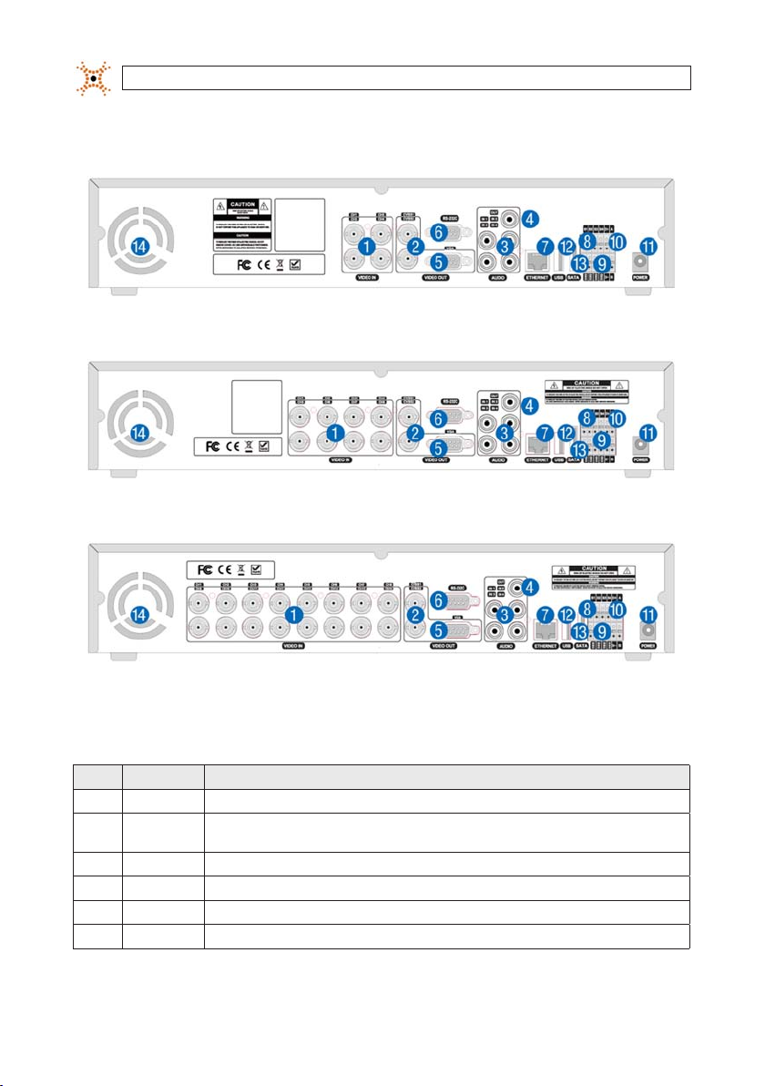
2.2 Rear panel
4-Channel DVR Rear Pane l
8-Channel DVR Rear Panel
Table 3. Rear Panel Connectors
No. Name Descr iption
1 VIDEO IN 16 conne ctors for v ideo input.
2 CVBS
3 AUDIO IN 4 RC A connector s for audio input .
4 AUDIO OUT R CA connect or for audio out put.
5 VGA Conn ector for a VGA m onitor.
6 RS-232 For fac tory use onl y.
4
www.digiop.com
Spot out 1: Live v iew screen.
Spot out 2: O ne channel scre en with an event i mage.
16-Channel DVR Rear Panel
SECTION 2: HARDWARE OVERVIEW
No. Name Descr iption
7 ETHERN ET R J-45 connec tor for LAN co nnection.
8 SENSOR IN 4 connector s for sensor dev ice connect ion.
9 ALARM OU T Conne ctor for alar m reporting d evice. Provid es simple On/O s witching by usi ng a relay. 0.5A/125V, 1A/30V
10 RS-4 85 RS-4 85 control ter minal
11 POWER SOC KET Connec t DC12V 5A adaptor
12 USB
13 SATA Conn ector for ex ternal SATA device
14 COOLING FAN
Use with a US B ash drive to arch ive still image s and videos, and u pgrade rmwa re, or use to conne ct a USB mouse to th e
DVR.
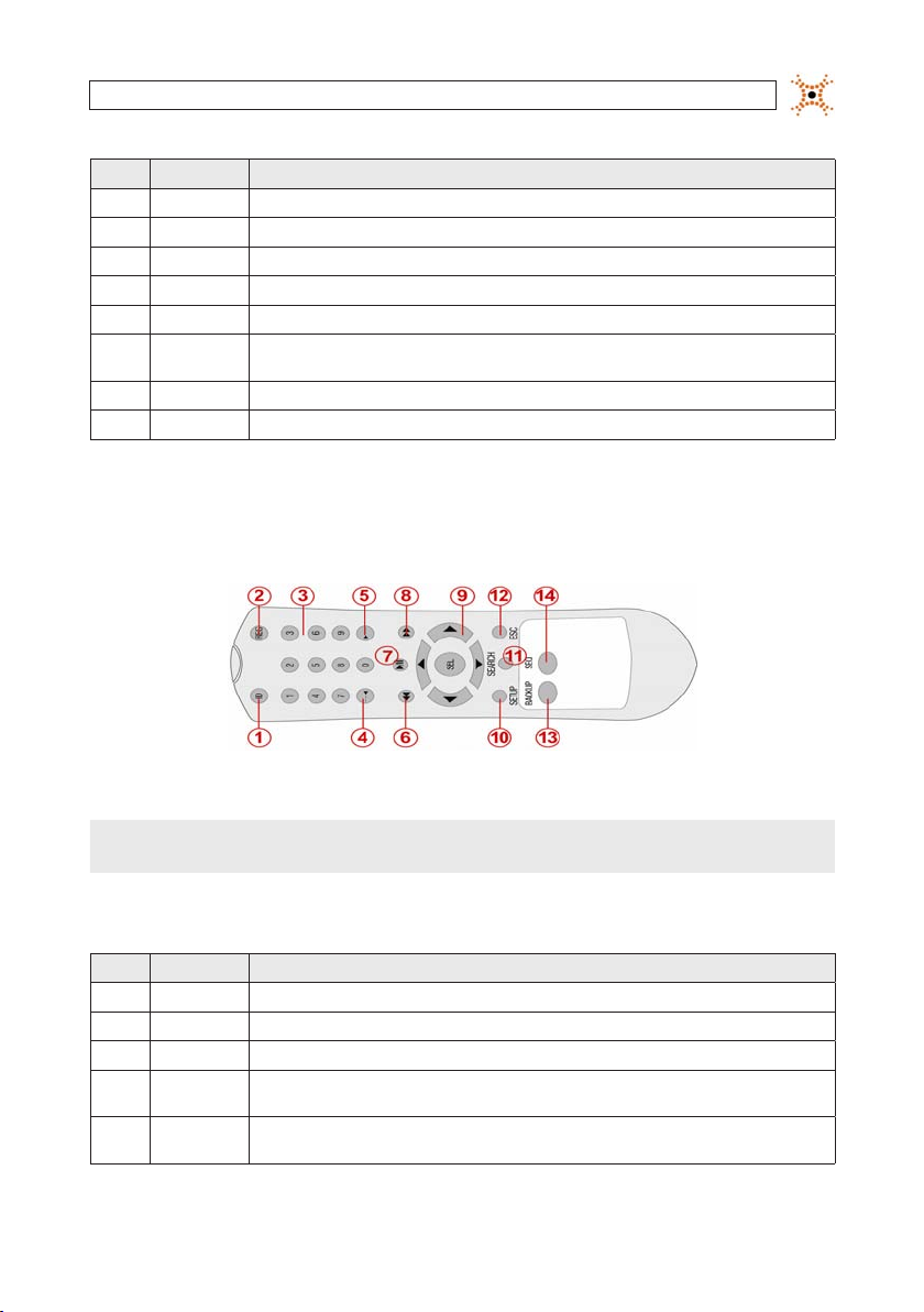
2.3 Remote Control
Typical Remote Control
NOTE
The remote control provided wi th your DVR may appear dierent from the o ne shown above. However, the buttons fu nction as
described in the tab le below.
Table 4. Remote Control Button Functions
No. Name Funct ion
1 ID When a remote c ontrol ID numbe r is setup in DVR, pr ess this but ton before th e number.
2 REC To start an d stop manual rec ording.
3 0 .. 9 To sele ct channel (1, 2, 3, ..) or to ente r a DVR ID number.
4 F/REW
5 F/ADV
During Pla yback – To move the play back positi on 60 seconds b ack.
During Pa use – To move the playba ck position 1 f rame back.
During Pla yback – To move the play back positi on 60 seconds f orward.
During Pa use – To move the playba ck position mo ves 1 frame for ward.
5H.264 DVR User Manual

SECTION 2: HARDWARE OVERVIEW
No. Name Funct ion
6 REW To rewind the reco rding at 1x, 2x, 4x , or 8x speed dur ing playback.
7 PLAY/PAUSE To play or to pause t he recording in p layback mode.
8 FF To fast forwar d the recording a t 1x, 2x, 4x, or 8x sp eeds during p layback.
Direc tion
9
Butto ns
10 SETUP To open the SE TUP menu.
11 SEARCH To go to the SEARC H menu.
12 ESC
13 BACKUP To st art a backup o perations in li ve or playback mo de.
14 SEQ To start auto s equencing th e screen in full s creen mode. ( Toggle)
Press to mo ve to menu items or se lect a channe l.
During s etup – To return to th e previous menu s creen.
During pl ayback – To exit play back mode
System lo ck – To lock a system w hen pressing ES C button for 5 s econds.
System unl ock – To unlock a sys tem when press ing ESC butto n for 5 seconds .
6
www.digiop.com
SECTION 3: SYSTEM SETUP
SECTION 3
System Setup
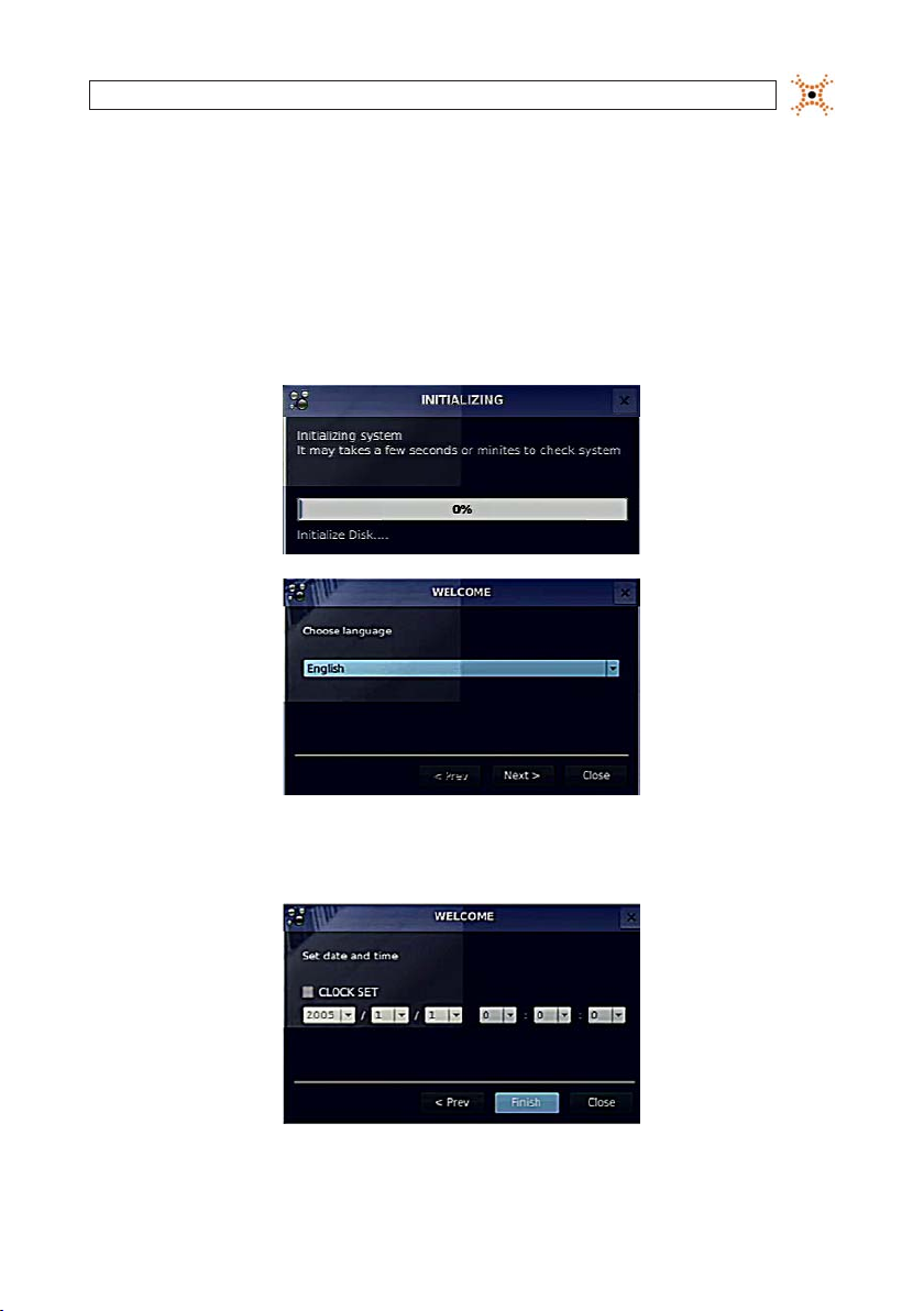
3.1 Starting the system for the rst time
When booting the system for the rst time, the f ollowing messages appear. After the initialization sequence completes, select your
preferred language and set the date and time.
When the Set date and time window opens, use the drop down lists to show the correc t date and time, then click Finish. The
date and time set ting is used to timestamp recordings.
7H.264 DVR User Manual
SECTION 3: SYSTEM SETUP
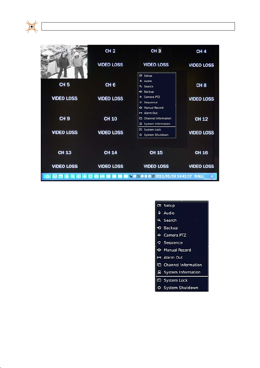
Typical System Desktop Display With One Camera Active
3.1.1 Entering the SETUP menu
1. To enter the SETUP menu, right click on the deskto p or
press the SETUP button on the remote control, then click
the Setup
entry in the p op-up menu. A LOG-IN window
will open.
2. In the LOG-IN window, open the virtual key board and enter the PASSWORD, or use the direction buttons on t he front panel.
The default password is “1111”. For improved securit y, DIGIOP recommends that you change the password at this t ime. You
can select a new password through the SECURIT Y tab in the SETUP menu.
8
www.digiop.com
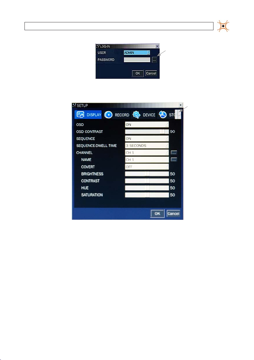
After entering the password, the SETUP window will open.
SECTION 3: SYSTEM SETUP
Virtual
Keyboard
Button
Shift
Tab List
Left/Right
Buttons
You can shift the tab list by clicking the le ft or right buttons in the upper-right corner of the window. Open a menu by
clicking the tab. To close the window, click Cancel. To save change s made to the menus before closing the window, click OK.
The SETUP menus inc lude the following tabs:
— DISPLAY
— RECORD
— DEVICE
— STORAGE
— SYSTEM
— SECURITY
— NETWORK
— CONFIG
— QUICK SETUP
For a summary of the elements in each SE TUP submenu (tab), refer to App endix C.
9H.264 DVR User Manual
SECTION 3: SYSTEM SETUP
Navigating the menus
Navigate through the menu items using the dire ction button, p, q, t, or u and change option values with the SEL
button. You can also navigate through the menu system, change option values, and click buttons with t he mouse. Always
select (or click) OK to s ave new settings and close the SETUP menus. Pre ss the ESC button at any time to ex it the SETUP
menus.
NOTE
In the followin g descriptions of the SETUP menus, th e instructions for navigat ing the system includes use of the f ront panel
buttons only. Using a mouse f or menu navigation and setup o f system options can be easier and faster.
3.2 DISPLAY menu
Opening the SET UP menu, or clicking the DISPLAY tab, opens the DISPLAY menu.
Open
Submenu
Button
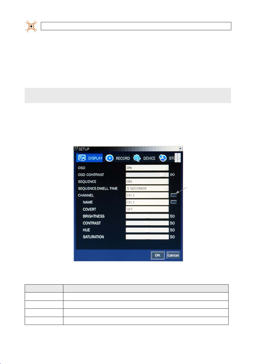
Table 5. DISPLAY menu options
Item Descr iption
OSD Enable/dis able the on-s creen display.
OSD CONTR AST Se t the visibilit y level of the OSD. (0 ~ 100)
SEQUENC E Enable/di sable sequen tial display of vi deo in full scre en mode.
SEQ-DWE LL TIME Set the dw ell time of each quad -split or 9- channel display in s equential di splay mode. (3 - 60 se conds)
10
www.digiop.com
Item Descr iption
CHANNEL
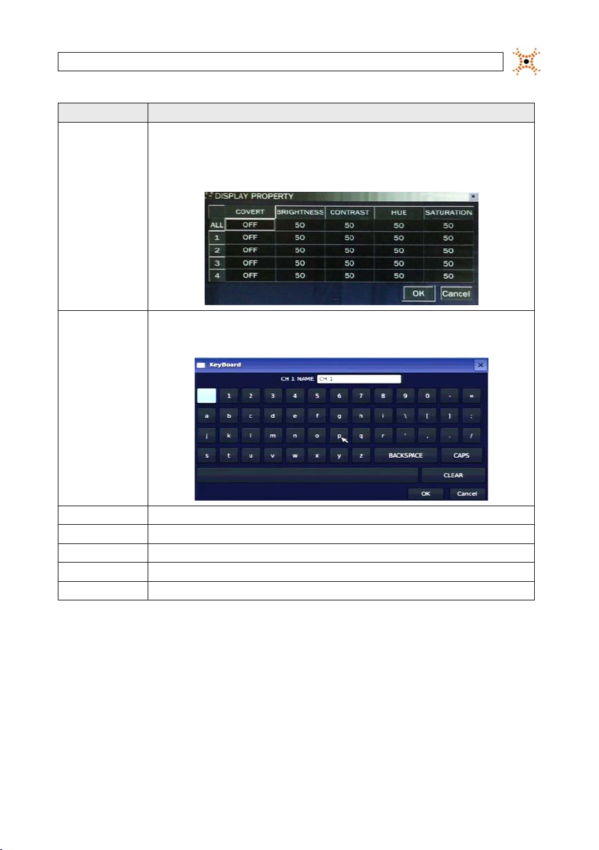
Highlight t he eld with th e p or q buttons, u se the t or u butt ons to display a chann el you want, then p ress SEL. You can
also highli ght and selec t the submenu bu tton to open th e DiSPLAY PROPERTY w indow.
In the DiSPL AY PROPERTY wind ow, use the p, q, t, and u bu ttons to highli ght a parameter, pre ss SEL, use the p, q, t,
and u but tons to change th e parameter valu e, then press SEL . Highlight the OK b utton and pre ss SEL to conrm t he setting s
and close t he window.
SECTION 3: SYSTEM SETUP
NAME
COVERT Enable/dis able display of th e specied v ideo channel in li ve display mode.
BRIGHTN ESS Change the bri ghtness value o f the selecte d channel. (0 ~ 100)
CONTRA ST Change the co ntrast value o f the select ed channel. (0 ~ 100)
HUE Change the h ue value of the sel ected chann el. (0 ~ 100)
SATURATION Change the sa turation valu e of the selec ted channel. (0 ~ 100)
Specif y the channel n ame. Press SEL to op en the virtu al keyboard, us e the p, q, t, and u but tons and SEL but ton to enter
the chann el name. Highlight t he OK button an d press SEL to con rm the sett ings and close t he keyboard win dow. The channel
name can have 10 c haracters a t most.
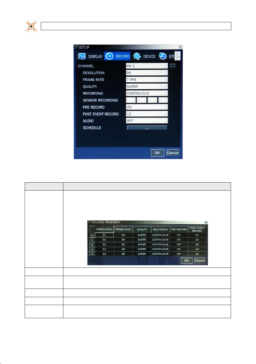
3.3 RECORD menu
Clicking the RECORD tab opens the RECORD menu.
11H.264 DVR User Manual
SECTION 3: SYSTEM SETUP
Table 6. Menu Items in Recording Mode Setup
Menu Item Des cription
CHANNEL
Highlight t he eld with th e p q buttons, us e the t u buttons t o display a channel y ou want, then pre ss SEL. You can also
highlight a nd select th e submenu but ton to open the RECO RD PROPERTY wi ndow.
In the RECOR D PROPERTY win dow, use the p, q, t, an d u buttons to hig hlight a paramet er, press SEL, use t he p, q, t,
and u but tons to change th e parameter valu e, then press SEL . Highlight the OK b utton and pre ss SEL to conrm t he setting s
and close t he window
.
RESOLU TION
FRAME R ATE S et the frame r ate for the spe cied channel . The sum of the fr ame rate values f rom each channe l cannot excee d the maximum
QUALITY Selec t the recording q uality for th e specied c hannel. Option s are: Networ k, Standard, Hig h, Superior and Ul tra.
RECORDIN G Assign t he recording mo de for each chann el. Options are: C ontinuous, By M otion, By Sens or, By Schedule, or D isable.
PRE RECORD Enable/disabl e pre-event re cording. Pre -event record ing time is 5 seco nds (video fro m 5 seconds bef ore the event is re corded
12
www.digiop.com
Selec t either CIF, Half D1, or D1 using the p, q, t, and u but tons.
frame r ates for a speci c recording r esolution. T he maximum vid eo frame rate is 120 f ps.
with the e ventt). Only intr a-frames a re recorded dur ing pre-eve nt recording.
SECTION 3: SYSTEM SETUP
Menu Item Des cription
POST EVE NT RECORD Set th e post event re cording time dur ation for the sp ecied chan nel. (10 ~ 30 seconds)
SENSOR RE CORDING
AUDIO Enable/dis able audio reco rding for the sp ecied chan nel. Available only o n channel 1 throu gh channel 4.
SCHEDUL E Set th e recording sc hedule. Press S EL to open the SCHE DULE window. .
Enable se tting up to 4 sen sors for the s pecied cha nnel using the p, q, t, or u but tons.
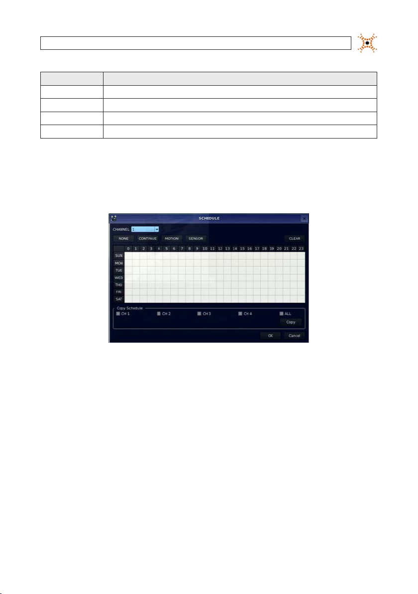
3.3.1 Recording Schedules
To setup a recording sche dule, select SCHEDULE in the RECORD menu. Navigate through the items using the p , q, t, and u
buttons.
[CHANNEL]: Select the specic channel.
[SETUP]: Use
p, q, t, and u buttons to highlight a timeslot in the schedule, then press SEL to apply the record t ype to that timeslot. Repeat
p and q buttons to highlight a record t ype (None, Continuous, Motion, Sensor), then press SEL to select it. Use the
this to apply other record types to other time slots. Select the AL L option to apply the schedule to all camer as channels. You can
select or deselect any option by clicking it w ith a mouse, and you can select a block of timeslot s by clicking and dragging the mouse
across them. Timeslots are color coded for the record type applie d to them: CONTINUOUS - green, MOTION - yellow, and SENSOR red, None - white.
[COPY Schedule]: To copy the schedule setup on channel 1 to channel 2, selec t the channel 1 schedule, selec t COPY using the
t,
and u buttons, s elect CH2 using the p, q, t, and u buttons, then press the SEL button.
p, q,
To return to SETUP menu scre en, press the ESC button.
13H.264 DVR User Manual
13
SECTION 3: SYSTEM SETUP
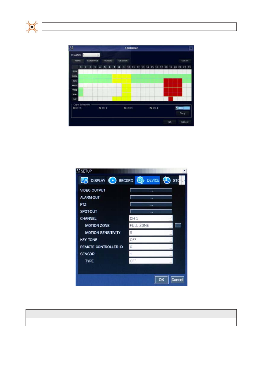
3.4 DEVICE menu
Clicking the DEVICE tab opens the DE VICE menu. To return to SETUP menu, press the ESC button.
Table 7. Menu Items in Device Setup Screen
Item Descr iption
VIDEO OUT Opens a sub menu to selec t the VGA video re solution: 1024 x 768 or 1280 x 1024
14
www.digiop.com
SECTION 3: SYSTEM SETUP
Item Descr iption
ALARM OU T Set the s ensor, motion, an d video loss for e ach alarm.
PTZ Set the PT Z camera spee d, number, type an d ID.
SPOT-OUT Set the co nguration f or SPOT 2 monitor ing only.
CHANNEL Selec t specied c hannel for motio n zone setup.
MOTION ZONE Select eith er Full Zone or Par tial Zone for mot ion sensing.
MOTION SEN SITIVITY Se t the motion sen sitivity f or the speci ed channel. (1 ~ 9).
KEY TONE Enable/disa ble tone when key is p ressed. .
REMOTE CON TROL ID Sel ect an ID for the r emote control.
SENSOR Selec t sensor numbe r. (1 ~ 4)
TYPE Set the t ype of sensor f or the speci ed channel. (OFF, N/O (norma l open), N/C (normal clos ed)).
1. Select I D number.
2. On the rem ote control, pre ss the same numb er as the ID set in th e DVR.
3. An icon will b e displayed on Liv e screen that co rresponds to t he remote contr ol. (0 ~ 99)
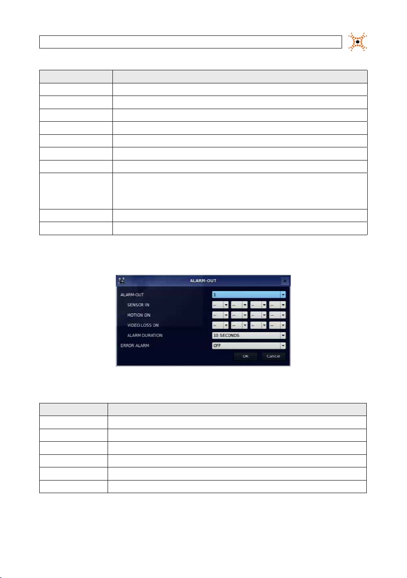
3.4.1 ALARM OUT submenu
Table 8. Menu Item in ALARM-OUT Setup Screen
Item Descr iption
ALARM OU T 1 only.
SENSOR IN Enable sett ing 1 of 4 cameras f or each alarm.
MOTION ON Enable settin g 1 of 4 cameras for e ach alarm.
VIDEO LOSS ON Enable se tting 1 of 4 came ras for each alar m.
ALARM DU RATION Set the a larm dwell time. (5 ~ 6 0 seconds).
ERROR AL ARM Set t he error typ e for the alarm ac tivation. (O FF, ALL, H DD ERROR, VIDE O LOSS).
15H.264 DVR User Manual
SECTION 3: SYSTEM SETUP
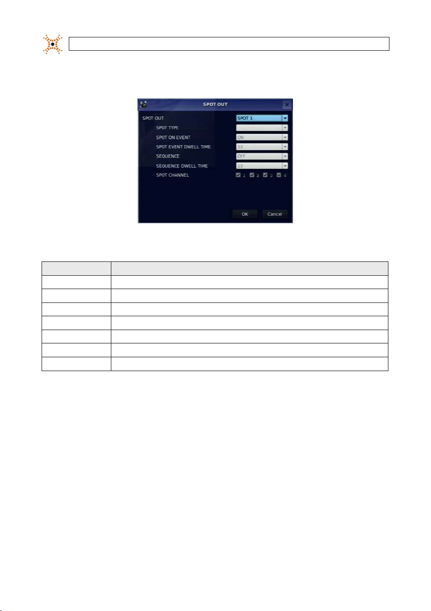
3.4.2 SPOT-OUT setup
Table 9. Menu Item in SPOT-OUT Setup Screen
Item De scriptio n
SPOT OUT SP OT 2 only
SPOT TYPE SPOT 2 suppo rts FULL t ype.
SPOT ON EVE NT Enable/disable dis play of the channel w hen an event is ac tive. SPOT 2 display s when event is ac tive.
SPOT EVEN T DWELL TIME Set the dw ell time for the e vent activate d channel (1 - 10 sec).
SEQUENC E Enable/dis able sequen tial display of spo t channel(s) in full sc reen. If ON is sel ected, the sp ot channel is disp layed.
SEQUENC E-DWELL TIME Set the dw ell time for the sp ot channel disp lay (1-10 sec).
SPOT CHANNE L
Selec t a channel for spo t monitoring. P ress SEL and sele ct channel us ing the p, q, t, and u bu ttons, then p ress SEL.
3.4.3 PTZ Setup
To control the PTZ func tions of the camera, connec t the PTZ controller to the RS-4 85 port on the back of the chassis with CAT 5 (or
equivalent) cable.
16
www.digiop.com

Open the PTZ submenu by selecting the submenu but ton.
SECTION 3: SYSTEM SETUP
RTS-485 D+
RTS-485 D-
NOTE
Connect speed do me cameras that support RS-4 85 directly to the RS-485 port. If t he camera is controlled through an RS-232C
interface, use an RS-232C to RS-485 signal conver ter.
Use the PTZ set up screen to select the following options for t he camera PTZ controller:
CHANNEL: Channel connected to a PTZ device
NAME: Protocol t ype
SPEED: 19200, 14400, 9600, 4 800, 2400
ID: 0 ~ 63
3.4.4 MOTION ZONE Setup
Select MOTION ZONE using the p, q, t, and u buttons, select either PARTIAL ZONE or FULL ZONE, t hen press SEL.
FULL ZONE: The motion sens or is active on the whole screen. Set the level of sensitivity for MOTION SENSITIVIT Y.
PARTIAL ZONE: The motion sensor is active in the s et detection frame (highlighted in green). To select or deselect a block
for motion dete ction, use the
DEVICE menu.
p, q, t, and u buttons to move to t he block, then press SEL. Pres s ESC to return to the
17H.264 DVR User Manual
SECTION 3: SYSTEM SETUP
Partial Zone Detectio n Area (in green)
3.5 STORAGE menu
Clicking the STOR AGE tab opens the storage menu. Navigate through the menu items using the p , q, t, and u buttons, press
SEL to select the item, use the
the next i tem you want to change using the
p, q, t, and u buttons to change the value, then press SEL again to conrm that value. Move to
p, q, t, and u buttons. To retur n to setup menu screen, press ESC.
18
www.digiop.com
SECTION 3: SYSTEM SETUP
Table 10. Menu Items in STORAGE Setup Screen
Item Descr iption
OVERWRIT E If ena bled, the DVR will co ntinue record ing when the dri ve is full, overw riting the ol dest inform ation rst. I f disabled, re cord-
DISK FORM AT Selec t YES or NO to for mat the hard driv e (disk). Caution: Fo rmatting t he hard drive will e rase all infor mation on the dis k.
DISK INFO Hard drive info rmation
RECORDIN G LIMIT Enable/dis able a recordin g limit.
RECORDIN G LIMIT DAYS Set the re cording limit in da ys (1- 90 days). If set to 1 day, data o lder than 24 hours wi ll be removed.
S.M.A. R.T. Use to set t he HDD temperat ure limit.
ing will st op when the hard dr ive is full.
Archive all d ata that you may ne ed before for matting th e disk.
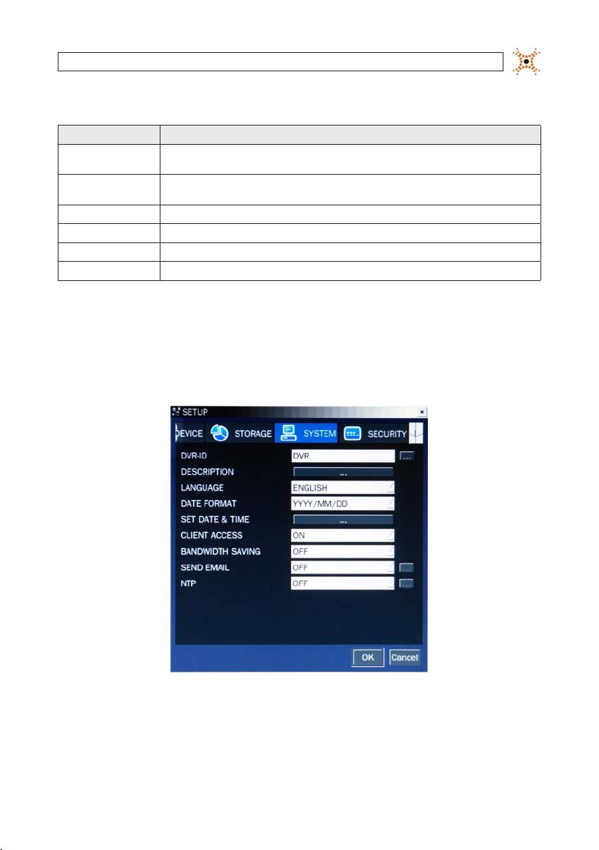
3.6 SYSTEM menu
Clicking the SYSTEM tab opens the s ystem menu. Navigate through the menu items using the p , q, t, and u buttons, press SEL
to select the item, use the
next item you want to change using the
p, q, t, and u buttons to change the value, then press SEL again to conrm that value. Move to the
p, q, t, and u buttons. To retur n to SETUP menu screen, press the ESC button.
19H.264 DVR User Manual
SECTION 3: SYSTEM SETUP
Table 11. Menu Items in SYSTEM Setup Screen
Item Descr iption
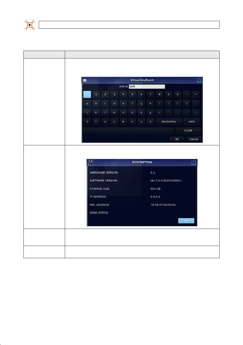
DVR ID
Selec t the submenu but ton to open th e virtual keyb oard. Press SE L to open the vir tual keyboard, u se the p, q, t, and
u and SEL but tons to enter the DV R ID, then highlight t he OK button an d press SEL to conr m your selec tion and close t he
keyboar d window. The DVR ID can h ave a most 10 charac ters.
DESCRI PTION Press th e SEL button to vi ew system inf ormation (har dware version, s oftware v ersion, stor age size, IP addre ss, MAC address ,
LANGUAGE
DATE FORMAT
and DDNS st atus).
Selec t the display langu age using the p, q, t, and u but tons. When a langu age is selec ted, the scree n language
changes . Options inclu de: English, Kore an, Japanese, SP C hinese, TR Chin ese, Czech, F innish, French, Gr eek, Italian, D utch,
Norse, R ussian, Spanish, Tur kish, Polish, Dani sh, Persian, Croa tian, German, Por tuguese, Po rtugues e (Brazil), Arabic ..
Selec t the date forma t using the p, q, t, an d u buttons. Op tions include : YYYY/MM/DD, MM/ DD/YYYY, DD/MM/ YYYY,
YYY Y-MM-DD, MM-DD-YY YY, DD-MM-YY YY.
20
www.digiop.com
Item Descr iption
SET DATE & TIME
To set the date an d time, move the cu rsor to SET DATE & TIME s ubmenu butto n using the p, q, t, and u butt ons, then
press th e SEL button.
In the SET DATE & TI ME window, use the t an d u buttons to ch ange the times tamp componen t value, then pre ss SEL to
conrm it a nd move to the nex t eld. To move to anoth er eld withou t changing it, u se the p and q but tons. Highlight
the OK but ton and press S EL to conrm your se lection and c lose the windo w, or press ESC but ton to return t o SYSTEM setu p
menu.
CLIENT ACCE SS Enab le/Disable r emote access thr ough networ k client soft ware.
BANDWIDTH
SAVING
SEND EMAI L Enabl e/disable the se nd email feature (O N/OFF).
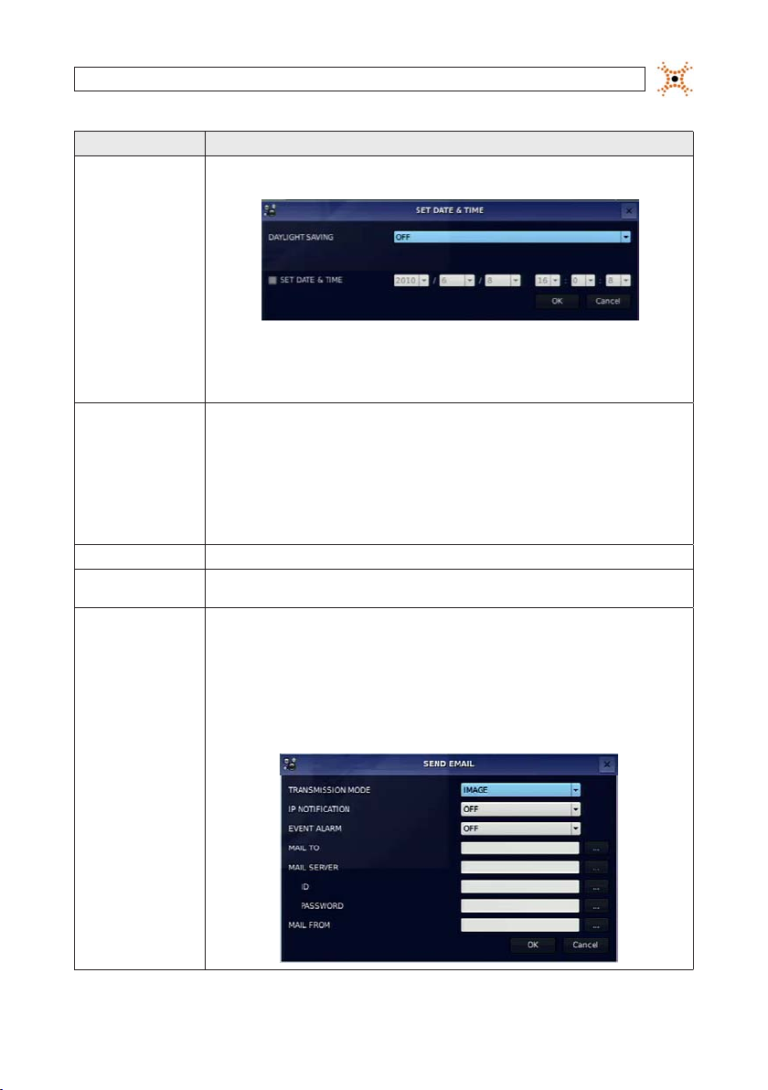
DAY LIGHT SAVING: Move t he cursor to DAYLIGH T SAVING using the p and q bu ttons, chan ge the option sho wn with the
t and u but tons, then pres s SEL to conrm your s election . Select the ap propriate day light saving tim e zone using the p,
q, t, and u bu ttons. If ch oosing EU or OTHER S, set the appli cable conditi ons. The optio ns are:
USA: Appli es the USA daylight s aving time.
EU: Applies t he EU daylight sav ing time. Selec t the GMT AREA an d the time die rence from st andard time usin g the p, q,
t, and u butt ons.
OTHERS: If t he time zone is nei ther USA nor EU, set t he BEGIN and END dat e and time of the day light saving per iod using the
p, q, t, and u bu ttons, then p ress the SEL but ton. Press th e ESC button to r eturn to SET DATE & TIM E setup menu.
CAUTION: D o not set the st art time to 23:0 0 for DLS. DLS c an’t be applied i f the date of BEGIN an d END is the same.
Enable/ Disable only key f rame transm ission. “ON” mo de is recommend ed for use on low- bandwidth n etworks . Set to “OFF”
for norm al use.
TRANSMIS SION MODE: When an a larm is trigge red, send an image o f only the channe l that trigger ed the alarm.
IP NOTIFIC ATION: Enable/disab le sending email w hen the IP addre ss of your DVR is chang ed.
EVENT ALA RM: When an alarm is t riggered, en able/disable se nding email repo rts of the ch annel that trig gered the alar m.
MAIL TO: Use t he virtual ke yboard to enter t he email addres s of the recipien t.
MAIL SERVER : Use the virt ual keyboard to e nter the mail ser ver informat ion.
ID: Use the v irtual keyb oard to specif y the user ID f or the mail ser ver.
PASSWORD: Us e the virtua l keyboard to spe cify the con nection pa ssword for th e mail server.
MAIL FROM: Us e the virtua l keyboard to spe cify the ema il address sent t o the destina tion host.
SECTION 3: SYSTEM SETUP
21H.264 DVR User Manual
SECTION 3: SYSTEM SETUP
Item Descr iption
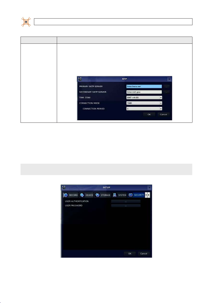
NTP NTP (Net work Time Proto col): Use to synch ronize the cloc ks of computer s ystems over va riable-late ncy data net works.
PRIMARY SNT P SERVER: Use the v irtual keyb oard to enter the ad dress of the pri mary NTP time s erver.
SECONDARY SNT P SERVER: Use the vi rtual keybo ard to enter the ad dress of the sec ondary NTP ti me server.
TIME ZONE: S elect the o set from GMT (Gre enwich Mean Tim e).
CONNECTO N MODE: Selec t an NTP time ser ver connect ion mode (INTER VAL/TIME).
INTERVAL: Syn chronize the clo ck by hours show n on the connec tion period o ption.
TIME: Sync hronize the clo ck at the time daily s hown on the conne ction per iod menu. CONNEC TION PERIOD : 1 ~ 24.
3.7 SECURITY menu
Clicking the SECURIT Y tab opens the securit y menu. Navigate through the menu items using the p, q, t, and u buttons, press
SEL to select the item, use the
the next i tem you want to change using the the
p, q, t, and u buttons to change the value, then press SEL again to conrm that value. Move to
p, q, t, and u buttons. To retur n to setup menu screen, press the ESC button.
NOTE
22
You must be a user with Admin p ermissions to congure the SECURITY menu.
www.digiop.com
SECTION 3: SYSTEM SETUP
Table 12. Menu Items in PASSWORD Setup Screen
Item Descr iption
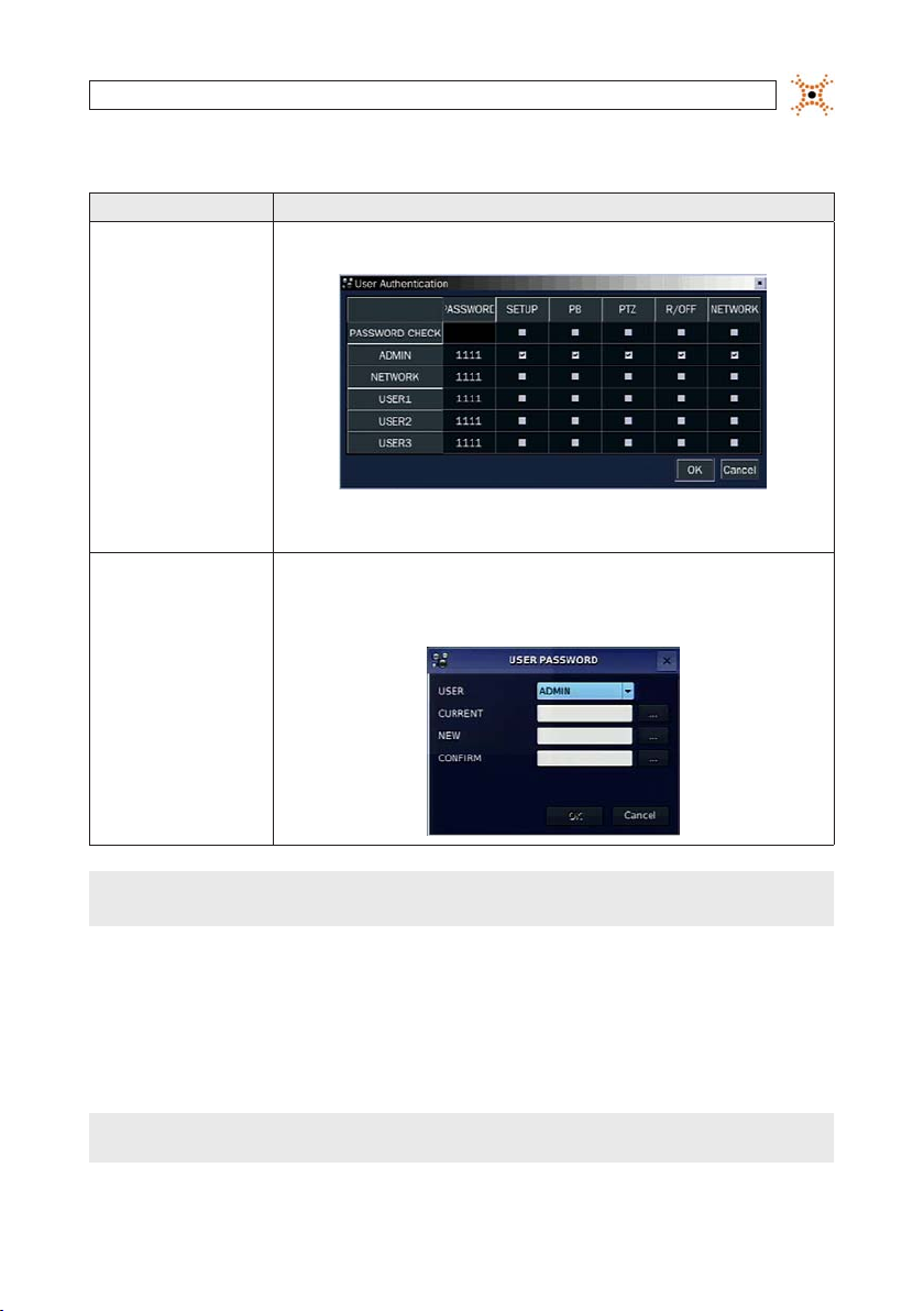
USER AUTHEN TICATION PAS SWORD CHECK: Sel ect either V o r nothing for th e function s such as SETUP, PB (playbac k), PTZ, R/OFF (reco rd o),
USER PASSWORD
and Net work.
In the PASSWOR D CHECK row, check o r uncheck the b ox to select fo r all users, or ch eck or unchec k the individual s ettings fo r each user. Press E SC to return to th e SECURITY menu .
In the USER PASS WORD window, move th e cursor to the USE R eld with p and q bu ttons, then u se the t and u
butto ns to display the us ername. Open t he virtual key board for each s ubsequent ent ry to speci fy the pass words. Move
to the OK bu tton and pres s SEL to conrm the s ettings and r eturn to the SEC URITY menu. Th e message “PASS WORD
CHANGED ” will be displayed . The factor y default pa ssword is 1111.
NOTE
For improved system secu rity, it is strongly recommended that you ch ange the factory defau lt password during the initial setu p
of your system.
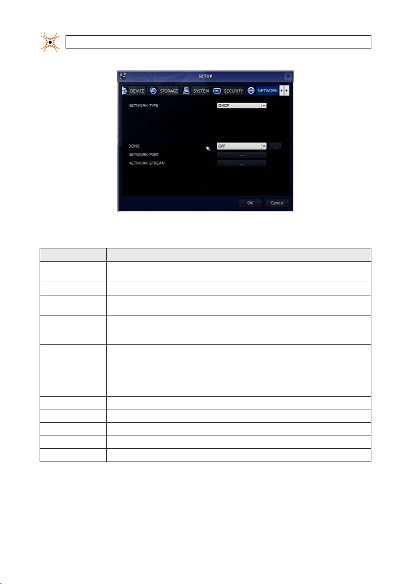
3.8 NETWORK menu
Clicking the SECURITY tab opens the securit y menu. Navigate through the menu items using the p, q, t , and u buttons, press
SEL to select the item, use the p, q, t, and u buttons to change the value, then press SEL again to conrm that value. Move to
the next i tem you want to change using the
NOTE
You must be a user with Admin p ermissions to congure the NETWORK m enu.
p, q, t , and u buttons. To return to set up menu screen, press ESC.
23H.264 DVR User Manual
SECTION 3: SYSTEM SETUP
Table 13. Menu Items in the NETWORK menu
Item Descr iption
NETWO RK TYPE Sele ct a type of n etwork conn ection. Op tions are: DHCP, ADSL, LAN . NOTE: Dependi ng on the selec tion, the opti ons in the
DHCP I f selected , the DVR automati cally acquires a n IP address fro m a DHCP server. Th is address may ch ange without n otice.
ADSL (PPPoE ) ID: R egistered ID i s necessar y for ADSL connec tion.
LAN IP: Enter th e IP address ass igned to the DVR. T his address is xed until it is man ually change.
DDNS Ena ble/disable use o f a domain name ser ver through wh ich you access the D VR. If “ON”, the DDNS ser ver name appear s in the
NETWO RK PORT Set a port n umber for conne cting to net work.
PORT Por t number (def ault: 5445)
WEB PORT Web s ever port num ber (default: 8 0)
PORT FORWAR D Se t the port fo rwarding fo r connectin g to network .
NETWO RK STREAM Set the value for n etwork st reaming.
netwo rk menu will chang e appropriate ly.
Passwo rd: A register ed password i s necessar y for an ADSL connec tion.
GATEWAY: Enter the Ga teway IP addres s assigned for t he DVR.
SUBNET MA SK: Enter the Sub net Mask for the s ubnet where th e DVR is connect ed.
eld.
DDNS 1: Selec t one of the follo wing DDNS ser vers: in USA, use w ww.ddnsce nter.com, in Korea, u se www.okdd ns.com, or
if in the eu, o r use www.be stddns.co m.
DDNS 2: Sele ct this typ e to use a general -purpose DD NS Server.
DDNS INTERVAL : Set the connec tion inter val (5 - 60 minutes).
24
www.digiop.com
 Loading...