

Observint Technologies BLK-DH200400DH, BLK-DH200800DH, BLK-DH201600DH, BLK-DH200400DHDVD, BLK-DH200800DHDVD Quick Start Manual
...
H.264 4/8/16 Channel DVR Quick Start Guide
Products: BLK-DH200400DH, BLK-DH200800DH, BLK-DH201600DH
PLEASE READ THIS GUIDE BEFORE USING YOUR RECORDER, and always follow
the instructions for safety and proper use. Save this guide for future reference.
BLK-DH20xx00DH_RQ
© 2012 Observint Technologies, Inc.

Specifications*
ITEM BLK-DH200400DH BLK-DH200800DH BLK-DH201600DH
Channel 4 channel 8 channel 16 channel
Input
Video
Output
Audio
Alarm
Record
Display Frame rate ( /sec) 30 fps/channel
Playback
Storage
User I/F
Serial port
Network
Network
Access
Features
Input / output 4 channel line input / 1 channel line output
Audio CODEC G.711 (ADPCM)
Sensor Input 4 channels (NC/NO selectable)
Alarm output 1 Alarm out by Sensor, Motion and Video Loss
Compression H.264
Multi-operation QUADPLEX (Playback/Record/Network/Backup)
Resolution
Recording quality grade 5 grades
Recording mode Continuous / Schedule / Motion/ Sensor/ Manual
Motion detection Motion detection setup by grid
Recording by channel Yes
Pre & post recording Yes, 10 sec. ~ 60 sec.
Multi-secoding 1, 4 1, 4, 8 1, 4, 8, 16
Playback speed
Search mode Timeline, Event, Archive, Log
HDD
E-SATA port 1
Backup
Serial ATA I port for DVD-RW 1
USB port 1 front, 1 back
Menu display GUI
Input method Remote control, mouse, keyboard (USB) controller
Console
PTZ control 1 RS-485
Ter mi na tio n Yes
Dynamic DNS Yes (free DDNS)
Network interface 10/100BASE-T Ethernet (RJ-45)
Network streaming CIF 120 fps / 100 fps
Web viewer (1:1) Live, Search, Backup, PTZF Cam Control, Remote Setup
3G mobile viewer (1:1) Live, search, PTZF
Single site monitoring system: Live, Search, Backup, PTZF Cam Control, Remote Setup
Multi-sites monitoring system Live, Search, Backup, PTZF Cam Control, Remote Setup
DLS (Day Light Saving) & NTP Yes
Internal Beep By Alarm, Motion, Video Loss, HDD error
Multi-Language Yes (more than 13 languages)
SW upgrade USB flash drive, network
Input level Composite, 1.0 Vp-p, 75 Ω
Signal format NTSC
Video loss check Yes
VGA 1
HDMI 1, up to 1080p
BNC 1
Spot 1
D1 120 fps 120 fps 120 fps
Half D1 120 fps 240 fps 240 fps
CIF 120 fps 240 fps 480 fps
Single channel 2x, 4x, 8x, 16x, 32x
Multiple channels 4 channels 4 channels 4 channels
Interface type Serial ATA I
Capacity of 1 HDD 2TB
Internal HDD 1 each (2 each without DVD-RW)
USB flash drive Video and still image
USB external HDD Video and still image
Network Video and still image
Page 2
ITEM BLK-DH200400DH BLK-DH200800DH BLK-DH201600DH
NTP Yes
Watermark
Power 12 Vdc @ 5 A
Operating temperature 41 °F ~ 104 °F (5 °C ~ 40 °C)
Storage temperature 14 °F ~ 122 °F (-10 °C ~ 50 °C)
Weight Unit weight / gross weight 9.04 lb / 13.67 lb (4.1 kg / 6.2 kg)
Dimension (w x h x d)
*Specifications and exterior design are subject to change without notice.
15.0” x 13.4” x 2.83” (380 mm x 340 mm x 72 mm)
Product Components
The package contains the DVR unit and the components shown below.
DVR unit
Software CD (with user manual) /
Quick Start Guide
/
HDD mounting screws (4)
Adaptor (DC 12V 5A) and power
cable
Mouse
Remote control and batteries
HDD mounting brackets (1 set)
HDD data power cable (1)
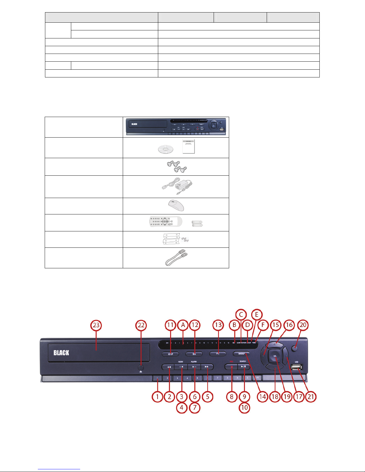
Front Panel
/
Page 3

Front Panel LEDs
No. Name Description
A
B
C
D
E
F
CH1~16
HDD
ALARM
NETWORK
BACKUP
POWER
Indicates that the channel is being recorded.
Indicates that the system is accessing the hard disk.
Indicates that sensor(s) is/are triggered or motion is detec ted.
Indicates that a network client is connected
Indicates that a USB or DVD-RW device contains stored data
Indicating that the system is switched on.
Front Panel Buttons
No. Name Description
1
2
3
4
5
6
7
8
Channel keys. For channel 10, press the 0 key. For channel 11, press the +10 and 1 key. For
channel 16, press the +10 and 6 key.
In playback mode, press to rewind the recording. Press again to increase the rewind
speed.
Press to select an audio mode:
MUTE – Mute all 4 channels.
SINGLE - Highlighted channel only.
MIX - Mix all 4 channels.
Jump/step backward. In playback mode, the playback position moves 60 seconds
backward.
In playback mode, press to fast forward the recording. Press again to increase the fast
forward speed.
Press to enable/disable ALARM operation.
Jump/step forward. In playback mode, the playback position moves 60 seconds forward.
Press to start or stop manual recording.
9
10
11
12
13
14
15
(LEFT)
In live display mode, press to open the SEARCH menu.
In playback mode, press to play/pause the footage.
Press to open the SETUP menu.
Enable/disable the automatic sequence of display of channels in full screen, quad, 9-split
display mode.
Press to control Pan/Tilt/Zoom operations.
Press to capture video in jpeg format in live or playback mode.
Press to move left or to change the values in Setup mode. It is also used as the number 4
when entering password.
Page 4

No.
C
R
A
W
A
n
T
A
C
A
Q
m
U
G
O
p
C
d
n
o
T
T
a
b
b
h
T
o
T
a
v
n
b
k
o
T
r
u
T
o
o
o
t
o
a
e
m
n
e
e
n
e
6
e
e
r
o
e
t
r
s
k
k
e
u
e
c
/
V
p
s
p
s
n
a
d
e
d
u
c
b
c
f
w
h
C
n
I
d
e
r
o
p
n
d
d
e
w
t
3
w
16
17
18
Na
(
(RI
(D
e
P)
HT)
WN)
Descriptio
Press to m
password.
Press to m
2 when en
Press to m
entering p
ve up the menu
ve right or to ch
ering password.
ve down the m
ssword.
in Setup mode.
ange the values
nu in Setup mo
It is also used as
in Setup mode.
e. It is also use
the number 1
t is also used as
as the number
hen entering
he number
when
19
20
21
22
23
Re
mote Control
USB
OPEN/
DVD
ort
LOSE
rive
Press to sel
Press for te
screen.
To s ave a s
USB flash d
Press to op
To save vid
ct desired men
porary storag
apshot image o
rive, first conne
n or close the d
o, insert a CD-R
item or to stor
of the changed
r video clip on a
t the USB flash
isk tray.
DVD-R
the setup valu
value or to retu
USB flash drive,
rive to the USB
.
n to the previou
r upgrade firm
ort.
s menu
are with a
No.
1
2
3
4
5
6
7
8
9
10
11
12
13
14
ID
RE
mber
Nu
EW
F/
DV
F/
RE
Y/PAUSE
PL
FF
trol button
Co
UP
SE
RCH
SE
ES
CKUP
B
SE
Name
Descriptio
When a rem
o start and
o select ch
During play
During paus
During play
During paus
To r e w i n d t
o play or t
o fast forw
Press to mo
To open the
To open the
During setti
During play
System Loc
System Unl
o start ope
(The same f
o start aut
te control ID
stop manual r
nnel (1, 2, .. 1
ack - To mov
e - To move th
ack - To mov
e - To move th
e recording. P
pause the fo
rd the recordi
e the menu it
SETUP menu.
search menu.
g - To return
ack - To exit f
– To lock a sy
ck – To unloc
ations of bac
nction button
sequencing o
umber is set i
cording
) or to enter D
the playback
e playback po
the playback
e playback po
ess again to in
tage in playba
ng. Press agai
ms or select c
o previous me
om playback
tem when pre
a system whe
up in live or pl
as CAPTURE o
f the screen in
n the DVR, inp
R ID number.
osition 60 se
ition 1 frame
osition 60 se
ition 1 frame
crease the re
ck mode.
to increase t
hannel.
nu screen.
ssing ESC butt
n pressing ES
yback mode.
n the front pa
full screen mo
t the DVR ID
onds backwar
ackward.
onds forward.
orward.
ind speed.
e fast forward
on for 5 secon
button for 5 s
el of DVR)
de. (Toggle)
umber.
.
speed.
s.
conds.
Page 5

R
e
e
e
D
D
D
C
m
o
d
d
D
-
A
A
t
B
-
s
e
u
o
u
ar Pan
BL
-DH200400
BL
-DH200800
l
H DVR
H DVR
BL
-DH201600
R
ar Panel
No. Ite
1 Co
2 Vi
3 Au
4 H
5 RS
6 VG
7 eS
8 Ne
9 US
10 RS
11 DC
H DVR
onnector
ling fan
eo input & vid
io Input
MI video outp
232C terminal
output
TA port
work RS-45 Et
port
485 PTZ, sens
12V Power Inp
o output
t
(For testing p
hernet port
r input (4), ala
ut
rposes)
rm output (1).
Refer to the User Manual for more information.
Page 6

System Installation and Setup
Follow the steps below to install and setup your system. For more information, refer to the user manual provided on the
CD.
1. Plan your entire installation carefully, considering:
Position of the cameras to effectively cover your surveillance targets. Avoid locations and orientations where
bright light might shine on or reflect onto the camera lens.
Security of the camera and the cabling to the DVR. Is it easy for an intruder to disable the cameras?
Location of the DVR. Is it in a secure location? Is the temperature and humidity within specifications?
2. Install your cameras in accordance with the manufacturer’s instructions.
3. Connect the video/audio and power extension cables to the cameras, then route them to the location of the DVR.
Note that video extension cables connectors are usually different at each end; the end with the male power connector
attaches to the camera drop cable, the end with the female power connector attaches to the power source and DVR.
4. Place the DVR on a clean, flat surface. Do not apply power to the DVR at this time.
Plug the USB mouse to the USB port on the DVR.
Connect a monitor to the VGA connector on the back of the DVR.
5. Connect the video extension cable from each camera to a video port on the back of your DVR.
If the camera location has a microphone, also attach the audio cable to an audio input connector on the back of
the DVR.
6. Attach the power extension cable to the cameras to the recommended power source to power them on.
7. Power on the DVR.
Connect the power adapter to the DC12V power connector on the back of the DVR.
Power on the monitor.
Connect the power cable to the power adapter and to a standard 120 VAC outlet. When the DVR is powering on,
an initialization window will appear.
8. When the CHOOSE LANGUAGE window opens, use the mouse to open the dropdown list, select the language you
prefer to use, then click Next. NOTE: You can also change the language setting later through the SETUP menus.
9. In the DAYLIGHT SAVING window, use the mouse to open the dropdown menus and select the DLS region, date and
time. When the correct date and time is shown, click Next. NOTE: The date and time setup in the DVR is used to
timestamp recorded video recordings. It is very important that this be set correctly if video recordings are used as
evidence.
Page 7

10. When the main screen opens, you should see a video image from each camera. Use this image to refine the manual
settings of the camera. These settings include the camera direction, and may include focus, zoom, and other settings.
11. Right click the mouse anywhere on the DVR screen then click SETUP, or press the SETUP button on the front panel to
access the SETUP menu.
If a LOGIN window opens, click the virtual keyboard button (at the right of the password entry field) to open the
keyboard window. Use the keyboard to click in the default ADMIN password, “1111”, t h e n c l i c k OK. In the LOGIN
window, click OK again to open the DVR SETUP menus.
12. Configure the SETUP menus to customize the DVR settings for your system. Refer to the user manual included on the
CD for more information about DVR Setup and system configuration settings.
Page 8

Network Connections
LAN Connection – Using a crossover cable without a switching hub
Connect to the system directly using a crossover type network cable.
LAN Connection – Using a switching hub
Connect to the system using a hub (switching hub) and an Ethernet cable (10BASE-T/100BASE-TX CAT 5 LAN cable).
Internet (ADSL) Connection
Connect to the system using a router or ADSL modem and an Ethernet cable (10BASE-T/100BASE-TX CAT 5 LAN cable).
Smartphone Access
When your DVR is configured for access across the Internet, you can remotely monitor and control
you video security using the free smartphone app Blackhawk. This app features:
View from 1 to 16 cameras
View images in portrait or landscape (single channel)
Monitor multiple locations
3G/Wi-Fi compatible
For more information, and to download and install the app, go to:
®
Apple
Android™ phones: http://www.androidzoom.com/android_applications/tools/blackhawk_tlcv.html
iPhone®, iPod touch®, or iPad®: http://itunes.apple.com/app/blackhawk-for-iphone/id422091119?
Page 9
 Loading...